
GC5271WTK30 - Cooker Summit - Free user manual and instructions
Find the device manual for free GC5271WTK30 Summit in PDF.


| Product Type | Gas built-in cooktop |
| Brand | Summit |
| Model | GC5271WTK30 |
| Cutout Dimensions (W x D) | 553 x 473 mm (21 3/4 x 18 5/8 in) |
| Overall Dimensions (W x D x H) | Not specified in the manual |
| Number of Burners | 4 |
| Ultra-Rapid Burner | 11,000 Btu/h, pan diameter 24-26 cm |
| Rapid Burner | 10,000 Btu/h, pan diameter 20-22 cm |
| Semi-Rapid Burner | 6,100 Btu/h, pan diameter 16-18 cm |
| Auxiliary Burner | 3,550 Btu/h, pan diameter 10-14 cm |
| Gas Supply | Natural gas or LPG (propane HD-5) |
| Supply Pressure | Natural gas: min 4" WC, max 11" WC; set to 1" WC above |
| Ignition | Integrated ignition via knob (emergency stop device) |
| Surface Material | Glass (likely, based on cleaning instructions) |
| Maintenance | Clean burners and grates with warm soapy water; do not use abrasive products |
| Safety | Emergency stop, gas shut-off, flame detection (thermocouple) |
| Spare Parts | Nozzles, taps, gaskets, grates available |
| Warranty | 1 year parts and labor (contiguous United States) |
| Country of Manufacture | Not specified |
Frequently Asked Questions - GC5271WTK30 Summit
User questions about GC5271WTK30 Summit
0 question about this device. Answer the ones you know or ask your own.
Ask a new question about this device
Download the instructions for your Cooker in PDF format for free! Find your manual GC5271WTK30 - Summit and take your electronic device back in hand. On this page are published all the documents necessary for the use of your device. GC5271WTK30 by Summit.
USER MANUAL GC5271WTK30 Summit
INSTRUCTIONS AND RECOMMENDATIONS FOR THE USE, INSTALLATION AND MAINTENANCE OF BUILT-IN GAS COOKTOPS
Dear customer,
Thank you for buying one of our products.
We are sure that this new, modern, functional and practical appliance, made using the finest quality materials, will fully satisfy your requirements. This new appliance is very easy to use, but in order to obtain the best results, we strongly recommend that you read this booklet carefully before use.
These instructions are valid exclusively for countries indicated on the label of the appliance.
The manufacturer cannot be considered responsible for any damages to people or to things in the event of incorrect installation or improper use of the appliance.
Felix Storch, Inc.
Summit Appliance Division
An ISO 9001:2015 registered company
770 Garrison Avenue
Bronx, New York 10474
www.summitappliance.com

PROFESSIONAL
MODEL: GC22SS - GC527SS - GC5271W - GC5272B
The Manufacturer cannot be held responsible for any imprecision due to printing or copying errors contained in this booklet. The figures shown are purely indicative. We reserve the right to make any changes to our products which we consider to be necessary or useful, also in the interest of the user, without affecting their essential characteristics in terms of functionality and safety.
This cooktop was designed to be used exclusively as a cooking appliance: any other use (such as heating rooms) is to be considered improper and dangerous.
TABLE OF CONTENTS
Important Safeguards....3
Location of Parts 4
Installation.... 5 - 8
Installing the Cooktop. 5
Sealing the Cooktop. 6
Room Ventilation. 6
Gas Connection. 7
Electrical Connection. 8
Adjustments....9
Conversions.... 10-11
Using the Cooktop....12
Lighting the Burners.... 12
Proper Use of the Burners. 12-13
Cleaning....14
Servicing....15
Replacing Components
Limited Warranty....16
IMPORTANT SAFEGUARDS
1) SAFETY INSTRUCTIONS
For all appliances:
- The product shall be installed according to the statement that the installation must conform with locabodes or, in the absence of local codes, with the National Fuel Gas Code, ANSI Z223.1/NFPA 54.
- The product must be electrically grounded in accordance with local codes or, in the absence of local codes, with the National Electrical Code, ANSI/NFPA 70.
- Make sure the gas connection complies with local codes and regulations. In the absence of local codes, installations must comply with the American National Standard, National Fuel Gas Code ANSI Z223 / NFPA 54 or Canadian CAN / CGA_B 149.1 or CAN / CGA-149.2.
- The appliance and its individual shutoff valve must be disconnected from the gas supply piping system during any pressure testing of that system at test pressures in excess of 12 psi (3.5 kPa). The maximum gas supply pressure is 4 inch WC and 11 inch WC and the gas pressure regulator provided is regulated to 1 inch water column above the manufacturer's specified manifold pressure.
- Always disconnect all cord-connected appliances before servicing. Appliances shall include instructions relative to location of the wall receptacle and a warning to the user to disconnect the electrical supply before servicing the appliance.
WARNING: If the information in this manual is not followed exactly, a fire or explosion may result causing property damage, personal injury or death.
- Do not store or use gasoline or other flammable vapors and liquids in the vicinity of this or any other appliance.
2) WHAT TO DO IF YOU SMELL GAS
- Do not try to light any appliance.
- Do not touch any electrical switch; do not use any phone in your building.
- Immediately call your gas supplier from a neighbor's phone.
Follow the gas supplier's instructions. - If you cannot reach your gas supplier, call the fire department.
- Installation and service must be performed by a qualified installer, service agency or the gas supplier.
- Save any nozzles removed from the appliance for future use.
- The maximum depth of cabinets installed above the cooktop should be 13 inches (330 mm).
- Keep the appliance clear and free from combustible materials, gasoline and other flammable vapors and liquids.
- Do not obstruct the flow of gas or block any air vents.
- Shut off gas to the unit by manually closing the independent gas valve before performing any pressure testing of the gas supply system with test pressures equal to or lower than 1/2 psi (3.5 kPa).
LOCATION OF PARTS
| MODEL : GC22SS | MODELS :GC527SSGC5271WGC5272B |
 |  |
art No.
Description
Heat supplied
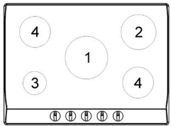
1 Ultra rapid burner 11 000 Btu/h
2 Fast burner 10 000 Btu/h
3 Auxiliary burner 3 550 Btu/h
4 Semirapid burner 6 100 Btu/h
6-7 Grate
8 Burner no. 1 control knob
9 Burner no. 3 control knob
10 Burner no. 2 control knob
11 Burner no. 4 control knob
NOTICE: This appliance has been manufactured for residential use only.
Warning: During operation the work surfaces of the cooking area become very hot: Keep children away!
INSTALLATION
Installation, adjustment of controls and maintenance must only be carried out by qualified personnel.
Incorrect installation may cause damage to persons, animals or property for which the Manufacturer will not be considered responsible. During the life of the system, the automatic safety or regulating devices on the appliance may only be modified by the manufacturer or by his duly authorized dealer.
Installing the Cooktop
Check that the appliance is in good condition after having removed the outer packaging and internal wrappings from around the various loose parts. In case of doubt, do not use the appliance and contact qualified personnel.
Never leave packaging materials (cardboard, bags, Styrofoam, nails, etc.) within the reach of children since these items could become sources of danger.
The measurements of the opening made in the top of the modular cabinet and into which the cooktop will be installed are indicated in Fig. 1 and the following chart. Always comply with the measurements given for the hole into which the appliance will be recessed (see Figs. 1 and 2).
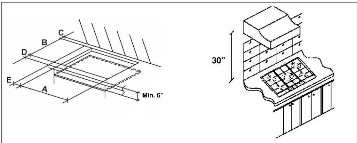
FIG. 1
FIG. 2
| Use These Dimensions (in inches) | |||||
| Model No. | A | B | C | D | E |
| GC22SS | 11^-1/4 | 19 | 2^-1/2 | 2^-1/2 | 2-7/8 |
| GC527SS – GC5271WGC5272B | 21-49/64 | 18-5/8 | 2^-1/2 | 2^-1/2 | 6 - 57/64 |
| Use These Dimensions (mm) | |||||
| Model No. | A | B | C | D | E |
| GC22SS | 282 | 482 | 59 | 59 | 100 |
| GC527SS – GC5271WGC5272B | 553 | 473 | 63,5 | 63,5 | 175 |
Sealing the Cooktop
The cooktop has a special seal which prevents liquid from infiltrating into the cabinet. Strictly comply with the following instructions in order to apply this seal correctly:
- Take off all the movable parts of the cooktop.
- Detach the seals from their backing, checking that the transparent protection still adheres to the seal itself.
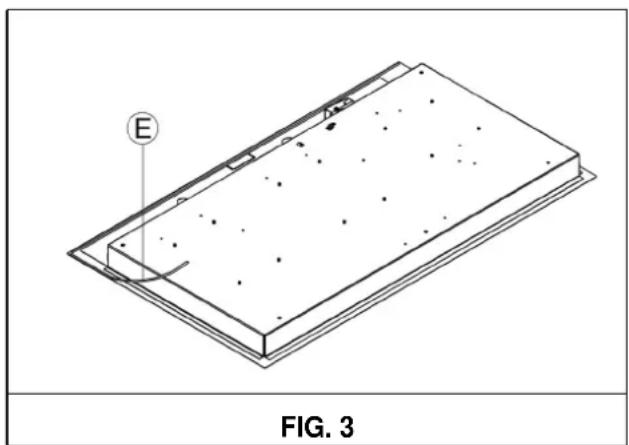
- Overturn the cooktop and correctly position seal "E" (fig. 3) under the edge of the cooktop itself, so that the outer side of the seal perfectly matches the outer edge of the cooktop. The ends of the stripst fit together without overlapping.
- Evenly and securely fix the seal to the cooktop, pressing into place with the fingers and remove the strip of protective transparent film from the seal and set the plate into the hole made in the cabinet.
- Fix the cooktop with the proper brackets “S” and fit the prominent part into the porthole “H” on the bottom; turn the screw “F” until the bracket “S” touches the top (fig. 4). In fastening the brackets, do not use a mechanical or electric screwdriver. Instead, use a hand-operated screwdriver and exert only moderate force.
The adjacent walls (left, right or behind) that exceed the cooktop in height must be at a minimum distance from the cut hole as indicated in Fig. 1 and the chart on the preceding page.
In order to avoid accidentally touching the hot cooktop bottom, it is necessary to put a horizontal wooden insert, attached by screws, at a minimum distance 6 below the lower surface of the cooktop (see Fig. 1).
Room Ventilation
To ensure proper operation of the appliance, be sure that the room where it is installed has adequate ventilation.
The appliance should not be installed with a ventilation system that blows air downward toward the appliance. It may cause ignition and combustion problems with the gas cooking appliance resulting in personal injury or unintended operation.
natural_image
Isometric technical drawing of a rectangular plate with internal holes and a labeled point E, no text or symbols present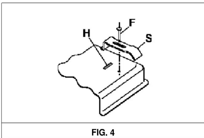
Gas Connection
Natural Gas and Propane Gas
Natural gas installations require the connection of a gas regulator to the cooktop. You will find this regulator among the accessories supplied with the appliance.
Assemble the regulator (noting the direction of gas flow) and transition pieces (supplied) in accordance with the figure below.
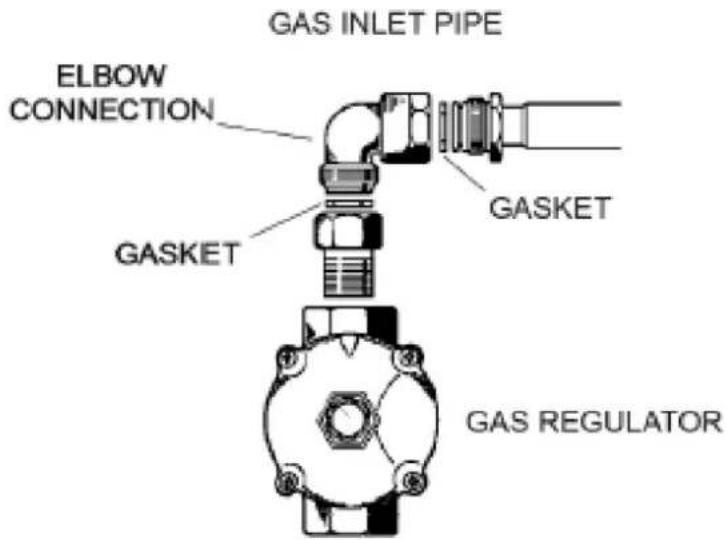
The transition piece on the supply side of the regulator must be provided by the installer. Unions compatible with the hose fittings must be used and connections tested for gas leaks.
Be sure that the supply connection point is accessible with the appliance installed.
WARNING:
Be sure the hose assembly is restrained from accidental contact with the flue or flue outlet of an under-counter oven.
Electrical Connection
The electrical connections of the appliance must be carried out in compliance with local standards and provisions.
Before connecting the appliance, check that:
-
The electrical capacity of the main electrical supply and current sockets suit the maximum power rating of the appliance. (See the data label attached to the bottom of the cooktop.)
-
The socket or system has an efficient ground connection in compliance with local standards and provisions. The manufacturer is not responsible for failure to comply with these provisions.
Electrical Connection
The electrical connections of the appliance must be carried out in compliance with local standards and provisions.
Before connecting the appliance, check that:
- The electrical capacity of the main electrical supply and current sockets suit the maximum power rating of the appliance. (See the data label attached to the bottom of the cooktop.)
- The socket or system has an efficient ground connection in compliance with local standards and provisions. The manufacturer is not responsible for failure to comply with these provisions.
When the appliance is connected to electrical power by a socket:
- Fit a standard plug suited to the load indicated on the data label to the cable.
- Fit the wires following Fig. 5, noting the following correspondences:
Letter L (live) = wire
Letter N (neutral) = wire
Ground symbol Ⓤ = green or yellow-green wire
- Never use adapters or shunts for connection since these could create false contacts and lead to dangerous overheating.
•The outlet must be accessible after the cooktop is built in.
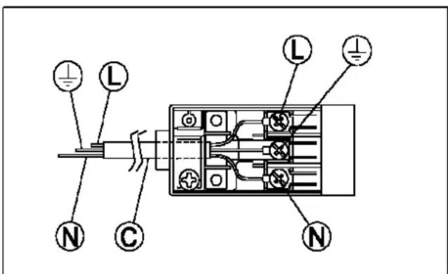
FIG. 5
When the appliance is connected directly to the electrical main:
• Install an omnipolar circuit-breaker between the appliance and the electrical main. This circuit-breaker should be sized in compliance with local installation regulations.
- Remember that the ground wire must not be interrupted by the circuit-breaker.
- For optimum safety, the electrical connection may also be protected by a high-sensitivity differential circuit-breaker.
You are strongly advised to fix the yellow-green ground wire to an efficient grounding system.
ADJUSTMENTS
Always disconnect the appliance from the electrical power source before making any adjustments. All seals must be replaced by the technician when any adjustments are completed.
Taps
"Reduced rate" adjustment:
- Switch on the burner and turn the relative knob to the "Reduced rate" position (small flame fig. 8 page 10).
- Remove knob "M" (fig. 6 and 6/A) of the tap, which is simply pressed on to its rod.
- The by-pass for minimal rate regulation can be: beside the tap (fig. 6) or inside the shaft. In any case, to access to regulation, it can be done trough the insertion of a small screwdriver "D" beside the tap (fig. 6) or in the hole "C" inside the shaft of the tap (fig 6/A).
Turn the throttle screw to the right or left until the burner flame has been adequately regulated to the "Reduced rate" position.
The flame should not be too low: the lowest small flame should be continuous and steady. Re-assemble the several components.
It is understood that only burners operating with Natural Gas or City Gas should be subjected to the above-mentioned adjustments. The screw must be fully locked when the burners operate with Propane (turn clockwise).
The operations described above can be carried out easily, whatever the position of the cooktop or however it is fastened to the work surface.
THE BURNERS DO NOT REQUIRE ANY REGULATION OF INCOMING AIR.
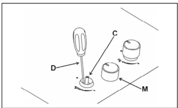
FIG. 6 FIG. 6/A

CONVERSIONS
Replacing Nozzles
The burners can be adapted to suit different types of gas by fitting the nozzles that correspond to the gas used. To do this, it is necessary to remove the burner heads and use a straight key "B" to unscrew the nozzle "A" (see Fig. 7) and replace it with a nozzle corresponding to the gas used.
Be sure the nozzle is seated tightly.
After making these replacements, the technician must regulate the burners as described in Adjustments on the previous page and apply the label corresponding to the new gas type in place of that previously applied. This label is contained in the spare nozzle bag.
How to change the setting of the pressure regulator supplied with the cooktop:
The gas regulator was set up to Natural Gas. To convert to LP Gas:
- Unscrew the aluminum cap
- Remove and turn the plastic pin 180°
- Screw in the plastic pin
- Screw in the aluminum cap
To make it easier for the fitter, we have prepared a table indicating the flow capacities, the heat capacities of the burners, the diameter of the nozzles and the working pressure for the various types of gas.


| BURNERS | GAS | NORMAL PRESSURE inches water column | INJECTOR DIAMETER 1/100 mm | NOMINAL HEAT INPUT (Btu/h) | ||
| N° | DESCRIPTION | Min. | Max. | |||
| 1 | ULTRA RAPID | PROPANE HD - 5 NATURAL GAS | 114 | 94176 | 4 4004 400 | 11 00011 000 |
| 2 | FAST | PROPANE HD - 5 NATURAL GAS | 114 | 91155 | 2 5002 500 | 10 00010 000 |
| 3 | AUXILIARY | PROPANE HD - 5 NATURAL GAS | 114 | 5390 | 1 2001 200 | 3 5503 550 |
| 4 | SEMIRAPID | PROPANE HD - 5 NATURAL GAS | 114 | 70120 | 1 5001 500 | 6 1006 100 |
USING THE COOKTOP
Lighting the burners
A diagram is screened beside each knob on the control panel of your cooktop. This diagram indicates to which burner the knob in question corresponds. After having opened the gas main or bottled gas tap, light the burners as described below:
The knobs of the burners are equipped with a safety cut-off device. They must be turned in a counterclockwise direction until they reach the full-on position (large flame icon, Fig. 8) and come to a stop. Now push down on the knob. The burner should ignite in 2 or 3 seconds. Keep the knob depressed as youturn it toward the reduced rate position (small flame icon, Fig. 8) to adjust the flame. Should the flame accidentally go out, turn the burner control knob off and wait at least 1 minute before attempting to lightit again.


natural_image
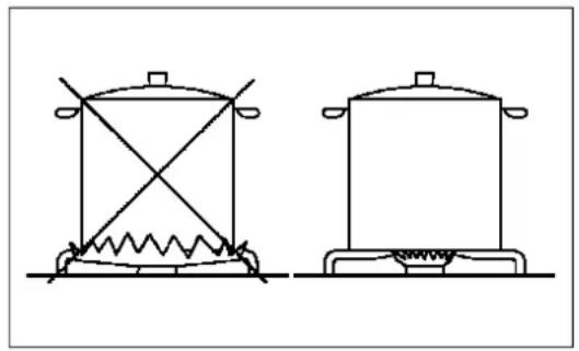
Two simple line drawings of a cooking pot with a spring and heating element, labeled FIG. 9 (no text or symbols on the diagrams)Proper use of the burners
To achieve maximum efficiency with the least possible gas consumption, keep the following instructions in mind:
- Use the correct pan size for each burner. (See the following table and Fig. 9.)
- When the pan comes to a boil, set the knob to a reduced rate position (small flame icon, Fig. 8).
• Always put lids on the pans. - Use only flat-bottomed pans.
| Burners | Power Ratings | Pan Diameter | In cm |
| ULTRA RAPID | 11 0000 | 9" to 10 1/2" | 24 - 26 |
| FAST | 10 000 | 8" to 9 1/2" | 20 - 22 |
| SEMIRAPID | 6 100 | 6" to 7 1/2" | 16 - 18 |
| AUXILIARY | 3 550 | 4" to 5 1/2" | 10 – 14 |
WARNINGS:
- Burners will only ignite when the corresponding knob has been set to the Full-on position (large flame icon, Fig. 8).
- Matches can be used to ignite the burners during a power outage, but use caution.
- Never leave the appliance unattended when the burners are being used. Make sure there are no children in the vicinity. In particular, make sure that the pan handles are correctly positioned. Keep checking on foods that require oil or other grease to cook since these products can easily catch fire.
- The appliance must not be used by people (including children) with impaired mental or physical capacities, or without experience of using electrical devices, unless supervised or instructed by an adult responsible for their safety and care. Children should not be allowed to play with the equipment.
- Never use aerosol sprays near the appliance when it is operating.
- Containers wider than the unit are not recommended.
NOTES:
- The use of a gas cooking appliance produces heat and moisture in the room in which it is installed. The room must therefore be well ventilated.
- Intensive and lengthy use of the appliance may require additional ventilation. This can be achieved by opening a window or by increasing the power of the mechanical exhaust system if installed.

WARNING!
NEVER use this appliance as a space heater to heat or warm the room. Doing so may result in carbon monoxide poisoning and overheating of the appliance.
CLEANING
IMPORTANT:
Always disconnect the appliance from the gas and electricity supplies before carrying out any cleaning operation.
Periodically wash the hot plate, the enameled steel pan support, the enameled burner caps "A", "B" and "C" and the burner heads "T" (see fig. 10 and 11) with lukewarm soapy water. Also clean plugs "AC" and flame detection "TC" (see fig. 10). Clean them gently with a small nylon brush as shown (see fig. 12) and allow to dry fully. Do not wash in the dishwasher. It is very important to clean the surface soon after every use, while the glass is still somewhat warm.
Do not allow vinegar, coffee, milk, salt water, or lemon or tomato juice to remain in contact with the enameled surfaces for long periods of time.
Do not clean using abrasive metal scourers, abrasive powders or corrosive sprays.
WARNINGS:
Comply with the following instructions, before remounting the parts:
- Check that burner head slots have not become clogged by foreign bodies.
- Check that enameled burner caps "A-B-C" (fig. 10-11) have been correctly positioned on the burner head. They must be steady.
- The exact position of the pan support is established by the rounded corners, which should be set towards the side edge of the hot plate.
- Do not force the taps if they are difficult to open or close. Contact customer service for technical assistance or repairs.
- Correctly preserve the plate after use by treating it with special, easily available products. This will keep the surface of the plate clean and bright. The operation will also prevent the formation of rust.
- Don't use steam jets to clean the equipment.
- Food burnt onto an electric plate must be removed dry.
- After use, pour a little lukewarm oil on the plate and wipe it with a cloth.
Note: Continuous use can cause the burners to change color due to the high temperature.

SERVICING
Always disconnect the appliance from the electric and gas supplies before proceeding with any servicing operation.
Replacing Components
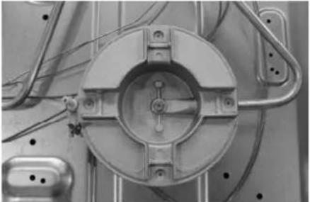
To replace the components housed inside the appliance, remove the trivets and the burners from the upper part of the cooktop. Remove the fixing screws "V" of the burner (Fig. 13) and the knobs using hand pressure to remove them from the appliance.
After having carried out these operations, the burners (Fig. 14), taps (Fig. 15) and electrical components can all be replaced (Fig. 16).
It is advisable to change seal "D" (Fig. 15) whenever a tap is replaced to ensure a perfect tightness.
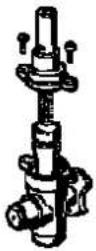
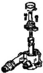
Greasing the taps (See Fig. 17-18)
If a tap becomes stiff to operate, it must be immediately greased in compliance with the following instructions:
- Remove the tap.
-
Clean the cone and its housing using a cloth soaked in solvent.
3 .Lightly grease the cone.
4 .Fit the cone back into place, operate it a few times and then remove it again. Eliminate any excess grease and check that the gas ducts have not become clogged. -
Fit all parts back into place, following the disassembly order in reverse.
-
The tight closure test must be done using a foaming liquid.
Never use a flame for this test.
WARNING: MAINTENANCE MUST ONLY BE PERFORMED BY AUTHORIZED PERSONS.
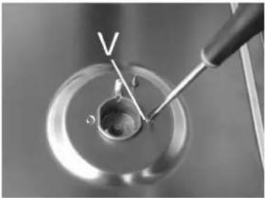 |  |  |
| FIG. 13 | FIG. 14 | FIG. 15 |
 |  |  |
| FIG. 16 | FIG. 17 | FIG. 18 |
LIMITED WARRANTY
Within the 48 contiguous United States, for one year from the date of purchase, when this appliance is operated and maintained according to instructions attached to or furnished with the product, warrantor will pay for factory-specified parts and repair labor to correct defects in materials or workmanship. Service must be provided by a designated service company. Outside the 48 states, all parts are warranted for one year from manufacturing defects. Plastic parts, shelves and cabinets are warranted to be manufactured to commercially acceptable standards, and are not covered from damage during handling or breakage.
ITEMS WARRANTOR WILL NOT PAY FOR:
- Service calls to correct the installation of your appliance, to instruct you how to use your appliance, to replace or repair fuses or to correct wiring or plumbing.
- Service calls to repair or replace appliance light bulbs or broken glass shelves. Consumable parts (such as filters) are excluded from warranty coverage.
- Damage resulting from accident, alteration, misuse, abuse, fire, flood, acts of God, improper installation, installation not in accordance with electrical or plumbing codes, or use of products not approved by warrantor.
- Replacement parts or repair labor costs for units operated outside the United States.
• Repairs to parts or systems resulting from unauthorized modifications made to the appliance. - The removal and reinstallation of your appliance if it is installed in an inaccessible location or is not installed in accordance with published installation instructions.
DISCLAIMER OF IMPLIED WARRANTIES; LIMITATION OF REMEDIES
CUSTOMER'S SOLE AND EXCLUSIVE REMEDY UNDER THIS LIMITED WARRANTY SHALL BE PRODUCT REPAIR AS PROVIDED HEREIN. IMPLIED WARRANTIES, INCLUDING WARRANTIES OF MERCHANTABILITY OR FITNESS FOR A PARTICULAR PURPOSE, ARE LIMITED TO ONE YEAR. WARRANTOR SHALL NOT BE LIABLE FOR INCIDENTAL OR CONSEQUENTIAL DAMAGES. SOME STATES DO NOT ALLOW THE EXCLUSION OR LIMITATION OF INCIDENTAL OR CONSEQUENTIAL DAMAGES, OR LIMITATIONS ON THE DURATION OF IMPLIED WARRANTIES OF MERCHANTABILITY OR FITNESS, SO THESE EXCLUSIONS OR LIMITATIONS MAY NOT APPLY TO YOU. THIS WARRANTY GIVES YOU SPECIFIC LEGAL RIGHTS AND YOU MAY ALSO HAVE OTHER RIGHTS, WHICH VARY FROM STATE TO STATE.

WARNING! This product can expose you to chemicals including Nickel (Metallic) which is own to the State of California to cause cancer.
For more information go to www.P65Warnings.ca.gov
Note: Nickel is a component in all stainless steel and some other metal components
Call customer service toll free in the U.S.A. @ 1-800-932-4267, Monday to Friday 9:00 am. - 5:00 p.m. (ET).
Order parts online at www.summitappliance.com/support

PROFESSIONAL
Felix Storch, Inc.
Summit Appliance Division
770 Garrison Avenue
Bronx, NY 10474
Phone: (718) 893-3900
Fax: (844) 478-8799
Web Site:
www.summitappliance.com
INSTRUCTIONS ET RECOMMENDATIONS POUR L'UTILISATION, L'INSTALLATION ET L'ENTRETIEN DE LA TABLE DE CUISSON AU GAZ ENCASTRABLE
Summit Appliance Division
natural_image
Technical diagram of a rectangular electronic component with labeled point E and scale bar, no readable text or symbols beyond labels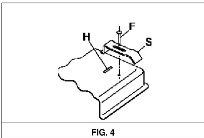
Raccordement au gaz
FIG. 5
FIG. 8 FIG. 9
natural_image
Two simple line drawings of a cooking pot with a wavy base and heating elements, no text or symbols present.Summit Appliance Division
770 Garrison Avenue
Bronx, NY 10474
- INSTRUCTIONS AND RECOMMENDATIONS FOR THE USE, INSTALLATION AND MAINTENANCE OF BUILT-IN GAS COOKTOPS
- TABLE OF CONTENTS
- IMPORTANT SAFEGUARDS
- 1) SAFETY INSTRUCTIONS
- 2) WHAT TO DO IF YOU SMELL GAS
- LOCATION OF PARTS
- art No.
- Description
- Heat supplied
- INSTALLATION
- Installing the Cooktop
- Sealing the Cooktop
- Room Ventilation
- Gas Connection
- Natural Gas and Propane Gas
- WARNING:
- Electrical Connection
- When the appliance is connected to electrical power by a socket:
- When the appliance is connected directly to the electrical main:
- ADJUSTMENTS
- Taps
- CONVERSIONS
- Replacing Nozzles
- USING THE COOKTOP
- Lighting the burners
- Proper use of the burners
- WARNINGS:
- NOTES:
- WARNING!
- CLEANING
- IMPORTANT:
- SERVICING
- Replacing Components
- Greasing the taps (See Fig. 17-18)
- WARNING: MAINTENANCE MUST ONLY BE PERFORMED BY AUTHORIZED PERSONS.
- LIMITED WARRANTY
- ITEMS WARRANTOR WILL NOT PAY FOR:
- DISCLAIMER OF IMPLIED WARRANTIES; LIMITATION OF REMEDIES
- INSTRUCTIONS ET RECOMMENDATIONS POUR L'UTILISATION, L'INSTALLATION ET L'ENTRETIEN DE LA TABLE DE CUISSON AU GAZ ENCASTRABLE
- Raccordement au gaz
Brand : Summit
Model : GC5271WTK30
Category : Cooker