
Prima AP F8.9 bit - Receiver AUDISON - Free user manual and instructions
Find the device manual for free Prima AP F8.9 bit AUDISON in PDF.


| Type | 9-channel car amplifier with integrated DSP |
| Brand | Audison |
| Model | Prima AP F8.9 bit |
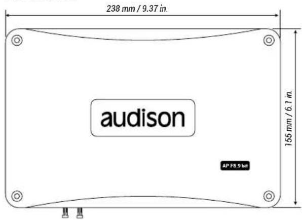
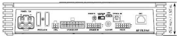
| Dimensions (W x H x D) | 238 x 49.5 x 155 mm / 9.37 x 1.95 x 6.1 in |
| Weight | 1.98 kg / 4.36 lb |
| Power Supply | 11 - 15 VDC, 2 x 30A blade fuses |
| Output Power (RMS @ 14.4 VDC, 1% THD) | 85 W x 8 @ 4Ω, 130 W x 8 @ 2Ω, 260 W x 4 bridged @ 4Ω |
| Total Harmonic Distortion (THD) | 0.06% @ 1 kHz, 4Ω, 70% rated power |
| Signal-to-Noise Ratio | 100 dBA (Master input), 105 dBA (Optical input) |
| Frequency Response | 10 Hz - 22 kHz @ -1.5 dB |
| Inputs | 6 Hi-Level (Speaker IN), 6 Pre-In (RCA), 1 Optical S/PDIF (up to 192 kHz / 24 bit) |
| Outputs | 8 amplified channels (bridgeable), 1 pre-amplified Sub Out (4 V RMS) |
| Digital Signal Processor | 32 bit, 147 MHz clock, 24 bit AD/DA converter |
| Filter Types | Butterworth (6/12/18/24 dB/oct), Linkwitz-Riley (12/24 dB/oct) |
| Crossover Frequency | 68 steps from 20 Hz to 20 kHz |
| Equalizer | 10-band parametric EQ per output channel (±12 dB) |
| Time Alignment | 0 - 510 cm (0 - 15 ms), step 0.08 ms, fine step 0.02 ms |
| Presets | 8 preloaded presets (7 fixed + 1 editable) |
| Remote Control | Optional DRC MP or DRC AB (volume, input, memory, bass boost) |
| PC Connectivity | USB micro-B (USB 1.1/2.0/3.0 compatible) for software tuning |
| Firmware Upgrade | Via USB and UPGRADE switch |
Frequently Asked Questions - Prima AP F8.9 bit AUDISON
User questions about Prima AP F8.9 bit AUDISON
0 question about this device. Answer the ones you know or ask your own.
Ask a new question about this device
Download the instructions for your Receiver in PDF format for free! Find your manual Prima AP F8.9 bit - AUDISON and take your electronic device back in hand. On this page are published all the documents necessary for the use of your device. Prima AP F8.9 bit by AUDISON.
USER MANUAL Prima AP F8.9 bit AUDISON
natural_image
Technical line drawing of a mechanical component with no visible text or symbols
FORZA
AP F8.9 bit
USER'S
MANUAL
rel. 1.0d
Index
- PRODUCT DESCRIPTION / PRECAUTIONS 3
- PACKAGE CONTENTS 3
- AP F8.9 bit and DRC INSTALLATION 4
- CONNECTION PANEL DESCRIPTION 5
1 POWER 5
2 CTRL (REM IN-OUT. / CONTROL)....6
3 SPEAKER IN....6
4 PRE IN....7
5 SPEAKER OUT....7
6 SUB OUT 8
7 OPTICAL IN 8
8 DRC 8
9 USB 8
10 UPGRADE OFF-ON 8
11 PRESET 8
12 FUSE 8
13 LOGO STATUS....9
- CONNECTIONS 10
5.1 POWER SUPPLY AND REMOTE TURN ON....10
5.2 INPUT SIGNALS 11
5.3 DIGITAL OPTICAL IN INPUT SIGNALS 14
5.4 OUTPUT SIGNALS....15
5.4.1 PRESET 0 DEFAULT: 3 WAY ACTIVE FRONT + REAR + EXTERNAL SUBWOOFER....16
5.4.2 PRESET 1: 2 WAY ACTIVE FRONT + 2 PASSIVE REAR + SUBWOOFER ....17
5.4.3 PRESET 2: 3 WAY ACTIVE FRONT + SUBWOOFER 18
5.4.4 PRESET 3: FRONT + REAR + SUBWOOFER 19
5.4.5 PRESET 4: 2 WAY ACTIVE FRONT + REAR + SUBWOOFER....20
5.4.6 PRESET 5: 3 WAY ACTIVE FRONT + REAR + EXTERNAL AMPLIFIED SUB .....21
5.4.7 PRESET 6: 2 WAY ACTIVE FRONT + REAR + EXTERNAL AMPLIFIED SUB 22
5.4.8 PRESET 7: 2 WAY ACTIVE FRONT + REAR + 2 WAY CENTER CHANNEL + EXTERNAL AMPLIFIED SUB... 23
5 PERSONAL COMPUTER AND DIGITAL REMOTE CONTROL (DRC)....24
- GUIDE FOR INSTALLING/UNINSTALLING AP F8.9 bit SOFTWARE AND DRIVERS 25
6.1 GUIDED PROCEDURE FOR PC SOFTWARE INSTALLATION 25
6.2 GUIDED PROCEDURE FOR DRIVER INSTALLATION 27
6.3 UNINSTALLING AP F8.9 bit SOFTWARE 28
- HOW TO SET UP AP F8.9 bit WITH A PC 29
7.1 OFFLINE MODE 29
7.2 TARGET MODE 30
7.3 ADJUSTING ACOUSTIC REPRODUCTION 36
7.3.1 DEVICE INFO....36
7.3.2 FILE MAIN MENU....37
7.3.3 MEMORIES MAIN MENU....37
7.3.4 SETTINGS MAIN MENU 38
7.3.5 DEVICE MAIN MENU 41
7.3.6 HELP MAIN MENU 42
7.3.7 SELECTED INPUT 42
7.3.8 CHANNEL MAP 42
7.3.9 SELECT CHANNEL 43
7.3.10 FILTER SETTINGS....43
7.3.11 SET DISTANCE AND DELAY 45
7.3.12 PARAMETRIC EQUALIZER 48
7.3.13 OUTPUT LEVEL 49
7.3.14 MEMORY 49
7.3.15 STATUS BAR 49
- TROUBLESHOOTING....50
8.1 SYNCHRONIZATION WITH A PC....51
8.2 BACKGROUND NOISE....52
8.3 FIRMWARE UPGRADE....53
- ACCESSORIES 53
9.1 DRC DIGITAL REMOTE CONTROL....53
9.1.1 DRC MP 53
9.1.2 DRC AB 53
9.2 SPM4 (Stereo Passive Mixer 4 Ch)....53
9.3 OP 1.5 TOSLINK OPTICAL CABLE 1,5 m / 59.05 in....54
9.4 OP 4.5 TOSLINK OPTICAL CABLE 4,5 m / 177.16 in....54
9.5 STA - F/F SOCKET TOSLINK ADAPTER....54
- TECHNICAL SPECIFICATIONS 55
1. PRODUCT DESCRIPTION / PRECAUTIONS
AP F8.9 bit is a 9-channel amplifier with 8 amplified channels settable in bridge mode; it also features a 32 bit, 147 MHz clock speed, 24 bit AD/DA converter digital sound processor (DSP), essential to maximize the acoustic performance of your car audio system.
It can be interfaced with any factory system, even on cars with built-in audio processors, since with the de-equalization function, AP F8.9 bit will send back a linear signal.
It features 13 signal inputs, 6 Hi-Level, 6 Pre-In and 1 S/PDIF optical digital and provides 8 amplified power outputs and 1 pre-amplified that is optimized to drive a subwoofer.
Each output channel provides: graphically adjustable parametric equalization group, 68-frequency steps electronic crossover and BUTTERWORTH or LINKWITZ filters with 6-24 dB slopes and a digital time delay line.
The user can make adjustments that allow him or her to interact with the AP F8.9 bit through the DRC MP remote control device.
WARNING: 1. A PC provided with Windows Vista, Windows 7 or Windows 8 operating system, 1.5 GHz minimum processor
speed, 2 GB RAM minimum memory and a 1024 x 600 pixels minimum resolution graphics card as well as at least 1 GB of available hard-disk space are required to install the software and setup the product. 2. Before connecting the product, carefully read this manual. Improper connections may cause damage to AP F8.9 bit or to the speakers in your car audio system.
2. PACKAGE CONTENTS
- AP F8.9 bit amplifier
- Multipolar cable, Rem/Control:
- Multipolar cable, Input Pre-IN:
- Multipolar cable, Input Speakers IN:
- Multipolar cable Speakers OUT:
- 2 - 30 A replacement fuse:
- 1.8 m USB cable:
- 2.5 mm hex key:
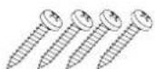
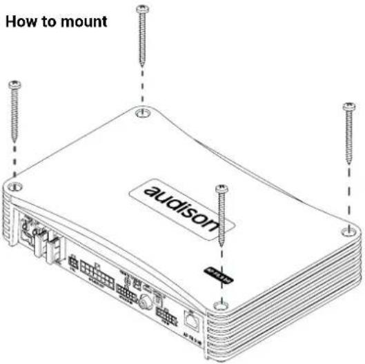
- 4 - 4.2 x 50 mm self-tapping, cross head mounting screws:
- CD ROM containing:
AP F8.9 bit Software
This owner's manual (.pdf)
Audio Test Tracks


3. AP F8.9 bit AND DRC INSTALLATION
External size
Mounting size

DRC MP (optional)

WARNING for all cable INPUT/OUTPUT

DRC AB (optional)

4. CONNECTION PANELS - DESCRIPTION


1 POWER.
+Power (11-15 VDC): connection terminal for AP F8.9 bit power supply positive pole. The jack accepts a stripped cable up to 15mm/0.6" with maximum section of 8 AWG (∅ 3,2mm / 0.12"). For better power transfer we recommend using cables with the largest possible cross-section and with the same cross-section as the cable connected to the negative pole.
- Power (Ground): connection terminal for the negative power supply pole of the amplifier. Connect here the negative battery cable or a cable connected to the vehicle chassis. The soket will take a stripped cable up to 15mm/0.6" with a maximum section of 8 AWG (∅ 3,2mm / 0.12"). For better power transfer, we recommend using cables with the largest possible section and with the same section as the cable connected to the positive pole.
In order to correctly connect the ground (-), use a screw that is already present on the metal part of the vehicle; if necessary, remove any paint residue or grease, using a tester to make sure there is continuity between the negative terminal (-) on the battery and the mounting point. If possible, connect all of the grounds on the audio components to the same grounding point. This helps reduce most of the interference than can occur in audio reproduction.
WARNING: make sure the connection polarity is as indicated on the terminals. A misconnection may result in damage to the AP F8.9 bit. After applying power, wait at least 10 seconds before turning the AP F8.9 bit on.

2 CTRL (REM IN-OUT / CONTROLS): terminals to turn on and control the AP F8.9bit.
- Remote IN. Input to turn on AP F8.9 bit remotely through the audio signal source Remote Out. REM IN can be connected to the ignition switch terminal (ACC). The voltage must be between 7 and 14.5 VDC. If using a source with amplified outputs such as BTL, AP F8.9bit can be automatically turned on (see sec. 7.2.5 - 7.3.4.7), so it will not be necessary to connect the REM IN terminal.
- Remote OUT. Output to turn on other devices/amplifiers connected after the AP F8.9 bit. From the time it is turned on, it takes 1 second to supply the signal to the REM OUT output, but it will be possible to set this delay via software (see sec. 7.3.4.7)
The 200 mA output current capability can also drive an automotive relay.
- OPTICAL SEL: it allows the OPTICAL input selection. This control is active bringing the terminal to +12V.
- MASTER EN: it enables the MASTER input selection. This control is active bringing the terminal to +12V. The control signals are interfaced with the AP F8.9 bit via a wiring featuring a 4 pole multipolar connector, described below.

3 SPEAKER IN.
AP F8.9 bit is provided with a 12 poles multipolar connector to manage the input signals. Connect up to a maximum of 6 input channels using the multipolar connector supplied.
By default AP F8.9 bit accepts signals coming from Front Left/ Front Right, Rear Left/ Rear Right, and the signal to be applied must have a value ranging between 2.2 and 22 V RMS. Such input channels can be then customized using the PC (see sec. 7.3.4.7).
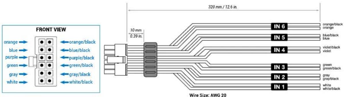
The channels FL FR RL RR feature the AUTO TURN ON (ART) function, automatic turn on/off, when connected with the source loudspeakers outputs. This function can be disabled via PC Software.
4 PRE IN
AP F8.9 bit is provided with a 12 pole multipolar connector to manage the PRE IN input signals, by soldering the RCA female connectors to the terminals, or using the accessory ACP6 to interface head units featuring a PRE OUT output. Connect up to a maximum of 6 input channels using the multipolar connector supplied or the extra cable provided with RCA connectors. By default the AP F8.9 bit accepts signals coming from Front Left/ Front Right, Rear Left/ Rear Right, Center/ Sub and the signal to be applied must have a value ranging between 0.6 and 6 V RMS (Fig.4). Such input channels can be then customized using the PC (see sec. 5.2 - 7.3.5).
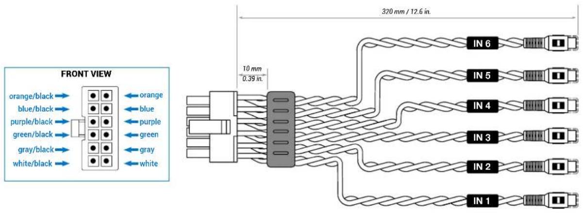
5 SPEAKER OUT.
AP F8.9 bit is provided with a 16 pole multipolar connector to manage the power output signals.

A minimum of 4 and a maximum of 8 speakers can be configured based on the system you wish to create in your vehicle. (see sec. 5.4)
6 SUB OUT.
Pre-amplified output subject to LO PASS filtering optimized to drive a mono amplifier for an external subwoofer or active subwoofer. (see sec. 5.4)
7 OPTICAL IN.
AP F8.9 bit accepts at its input PCM signals up to 192 kHz / 24 bit sampling frequency rate. So DOLBY DIGITAL (AC3) multi-channel signals coming from audio/video sources (such as the audio of a film in DVD) or DTS can not be reproduced. Connect a fiber optic cable with a TOSLINK connector. This input can be selected using the external DRC control or by activating it using the OPTICAL IN terminal. (see sec. 5.3)
8 DRC.
Connection terminal for remote control of the functions (OPTIONAL) of the AP F8.9 bit (see sec. 5.5)
9 USB.
USB (micro) connection to connect the product to a PC in order to manage the functions using AP F8.9 bit software. The connection is USB 1.1/2.0/3.0 compatible.
10 UPGRADE OFF-ON.
Switch ON allows the product to be updated in BOOT LOADER mode. (see sec. 8.3)
11 PRESET.
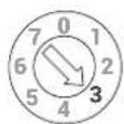
AP F8.9 bit features 8 setups preloaded in its memory, one being editable. They allow the product to be used without the need to connect it to a PC. (see sec. 5.4.1; 5.4.8). The preset choice is based on the factory system in the car or the type of system you wish to create.
12 FUSE.
30 A blade protection fuse. In case the fuse needs to be replaced, use same type and value as the original.

13 LOGO STATUS.
AP F8.9 bit is provided with a built-in control that manages its status and protects the circuits and connections to the speakers. The logo on the AP F8.9 bit top cover will change its status in case of any possible product malfunctions.
A BLUE logo means:
AP F8.9 bit is on.
Flashing RED/BLUE logo means:
The "UPGRADE MODE" switch on the product is set to "ON" position, or the product Firmware is being updated.
Flashing BLUE logo means:
The unit is in stand-by (energy saver) because there is no audio signal. This function (AST) can be activated using the PC software. (see sec. 7.3.4.7) and the stand-by time ranges from a minimum of 5 mins. to a maximum of 20 mins. The unit will automatically turn off after 30 mins. when there is no signal.
Flashing RED logo means:
- AP F8.9 bit temperature reached 75^ C and the thermal protection was triggered. It will start operating again at around 70^ C.
RED logo flashing twice every second means:
- Output overload. The red LED flashes when the output load goes below the minimum allowed capacity of about 2Ω impedance. The LED comes on without flashing, activating the protection. When listening to music, if the acoustic reproduction stops for a few seconds, check if the red amplifier LED is flashing. This means there was an overload. Turn the amplifier off and check the speakers and wirings. This protection is self-restoring. - Speaker wiring anomaly. The red LED flashes when a terminal on the speaker goes in short-circuit with the vehicle chassis. When listening to music, if the acoustic reproduction stops for a few seconds, check to see if the red amplifier LED is flashing; this means there was a short circuit between a terminal on a speaker and the vehicle chassis. Turn off the amplifier and check the speakers and wiring. This protection is self-restoring.
RED logo flashing four times every second means:
- The "OVER VOLTAGE" protection activation, due to the fact that the battery voltage is higher than 16V. The product will turn off after 3 minutes.
WARNING: check the state of charge of the car alternator.

RED logo means:
- Product internal fault. Please contact an authorized service centre. The product will turn off after 3 minutes.
5. CONNECTIONS
5.1 POWER SUPPLY AND REMOTE TURN ON
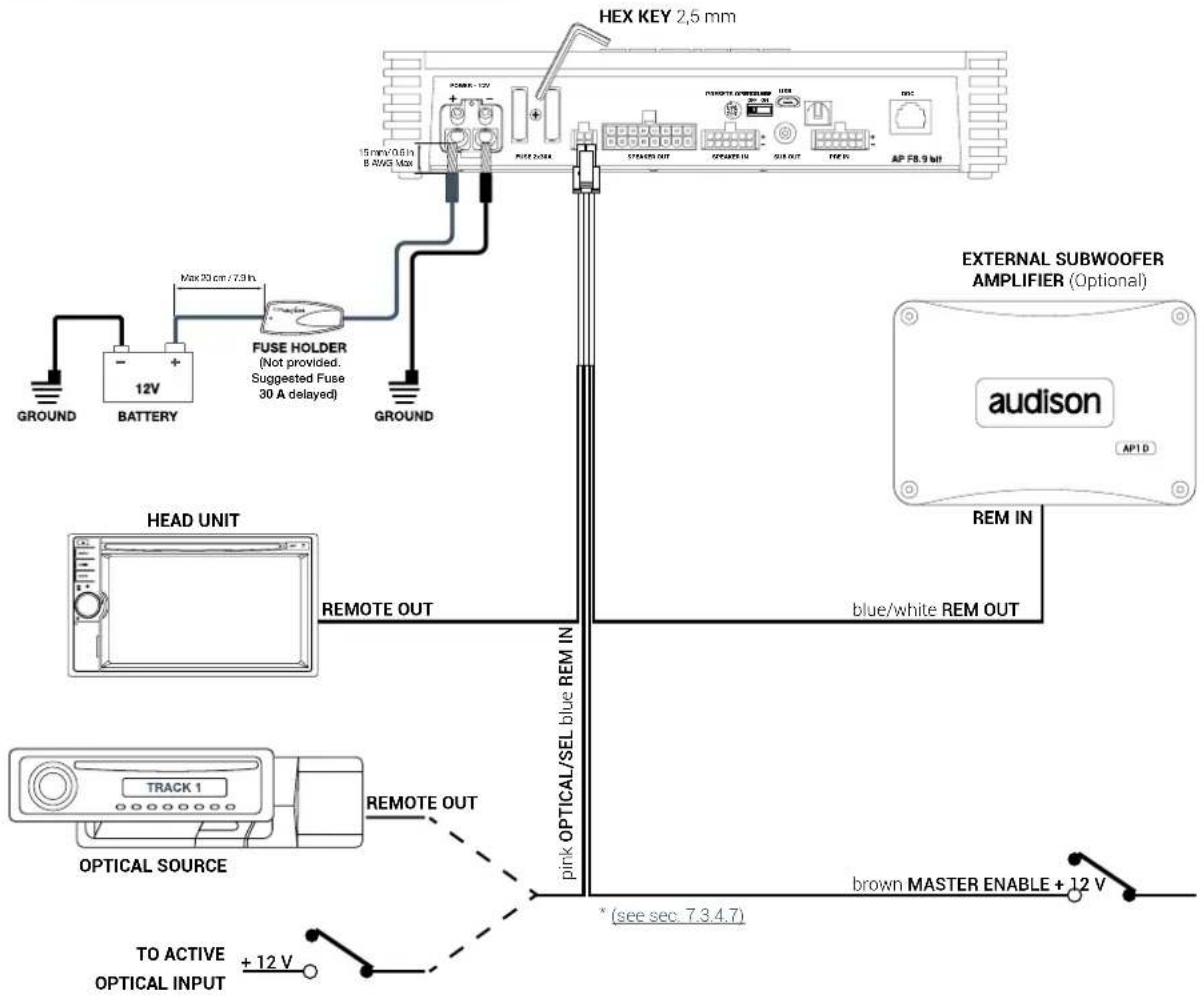
Turn AP F8.9 bit on and off
AP F8.9 bit is on when the logo is blue. It can be turned on/off using the following methods:
- By pressing on the main DRC control knob (ON). By holding down the main control knob on the DRC (OFF). In this case, no other Remote In connections are needed, but they can co-exist.
- By connecting the REMOTE IN terminal with a Remote Out signal coming from an after market audio source.
- Through the Hi Level MASTER (FL - FR) input. The AUTO TURN ON (ART) function is activated by connecting the output of an amplified source to the INPUT FL - FR input channel. This function can be enabled/disabled using AP F8.9 bit PC software (see sec. 7.3.4.7).
- Using the Speaker IN input. The AUTO TURN ON (AST) function is activated by connected the outputs on a amplified source to the input channels to the AP F8.9 bit input channels.
This function can be enabled/disabled using AP F8.9 bit PC Software. This turn on control is available on the IN 1; IN 2; IN 3; IN 4; IN5; IN6 inputs (see sec. 7.3.4.7).
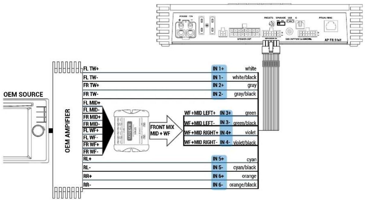
5.2 INPUT SIGNALS
1. SPEAKER INPUT: FRONT + REAR

2. SPEAKER INPUT: 2 WAY FRONT + REAR
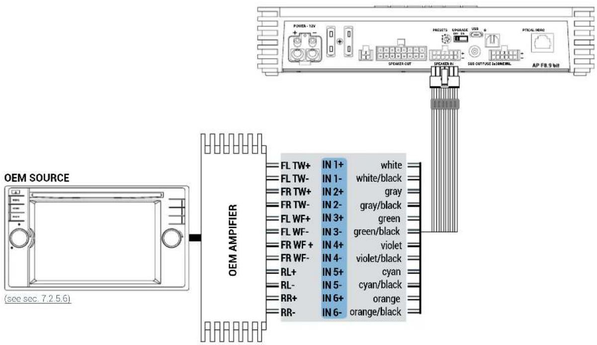
3. SPEAKER INPUT: FRONT + REAR + CENTER + SUB

4. SPEAKER INPUT: FRONT + REAR + LEFT SUB + RIGHT SUB
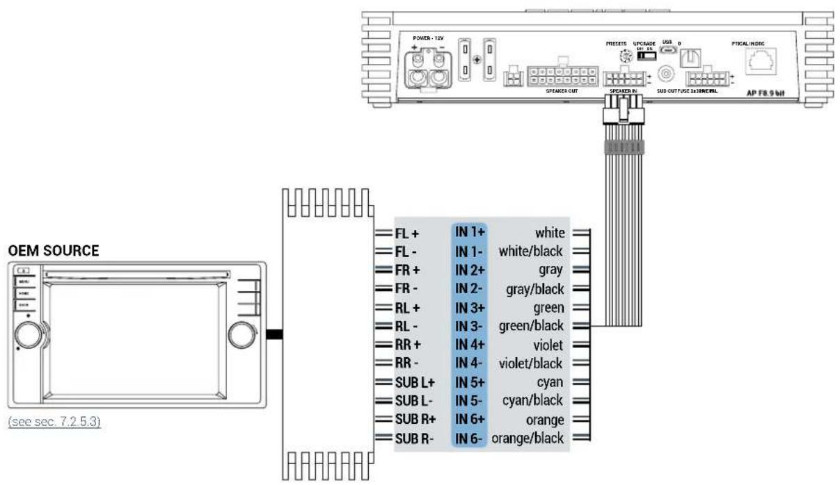
5. SPEAKER INPUT: 3 WAY FRONT + REAR
flowchart
graph TD
    A["POWER - 17A"] --> B["Speaker OUT"]
    B --> C["Speaker IN"]
    C --> D["UPGRADE USB G"]
    D --> E["AP FB.9 bit"]
    F["OEM SOURCE"] --> G["FL TW+"]
    F --> H["FL TW-"]
    F --> I["FR TW+"]
    F --> J["FR TW-"]
    F --> K["FL MID+"]
    F --> L["FL MID-"]
    F --> M["FR MID+"]
    F --> N["FR MID-"]
    F --> O["FL WF+"]
    F --> P["FL WF-"]
    F --> Q["FR WF+"]
    F --> R["FR WF-"]
    G --> S["IN 1+ white"]
    H --> T["IN 1- white/black"]
    I --> U["IN 2+ gray"]
    J --> V["IN 2- gray/black"]
    K --> W["FRMID LEFT+ IN 3+ green"]
    L --> X["FRMID LEFT- IN 3- green/black"]
    M --> Y["FRMID RIGHT+ IN 4+ violet"]
    N --> Z["FRMID RIGHT- IN 4- violet/black"]
    O --> AA["FRMID RIGHT- IN 5+ cyan"]
    P --> AB["FRMID RIGHT- IN 6+ orange"]
    Q --> AC["FRMID RIGHT- IN 6- orange/black"]
    R --> AD["RL+"]
    S --> AE["RL-"]
    T --> AF["RR+"]
    U --> AG["RR-"]
6. PRE INPUT FRONT + REAR + CENTER + SUB + REAR
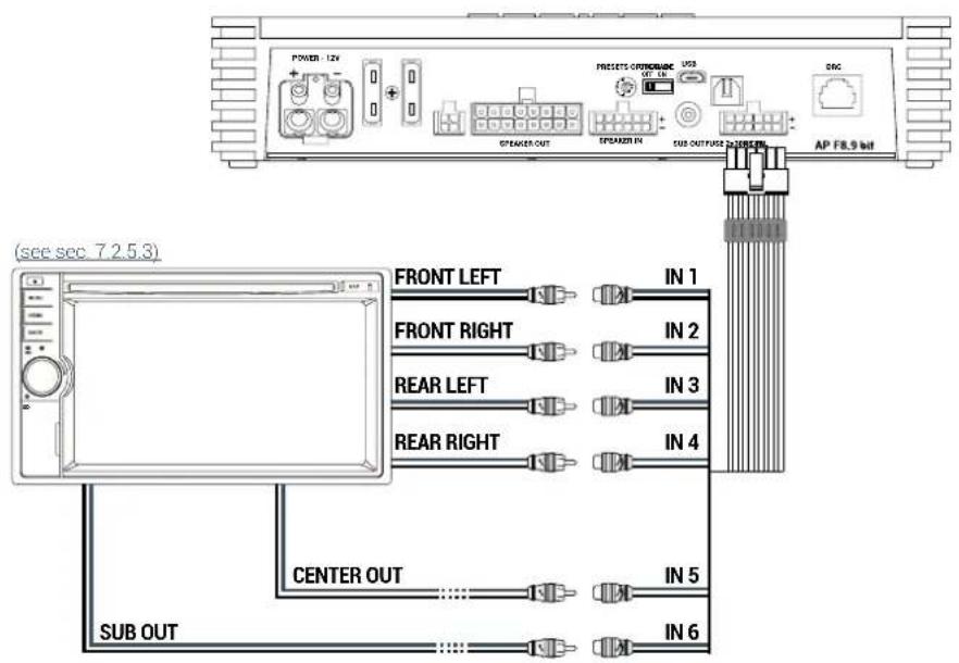
7. PRE INPUT FRONT + REAR + CENTER + SUB + REAR
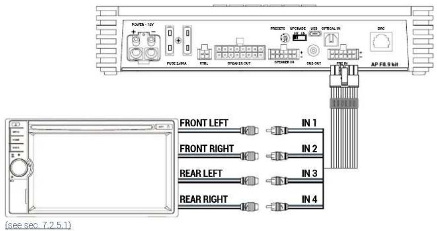
5.3 DIGITAL OPTICAL IN INPUT
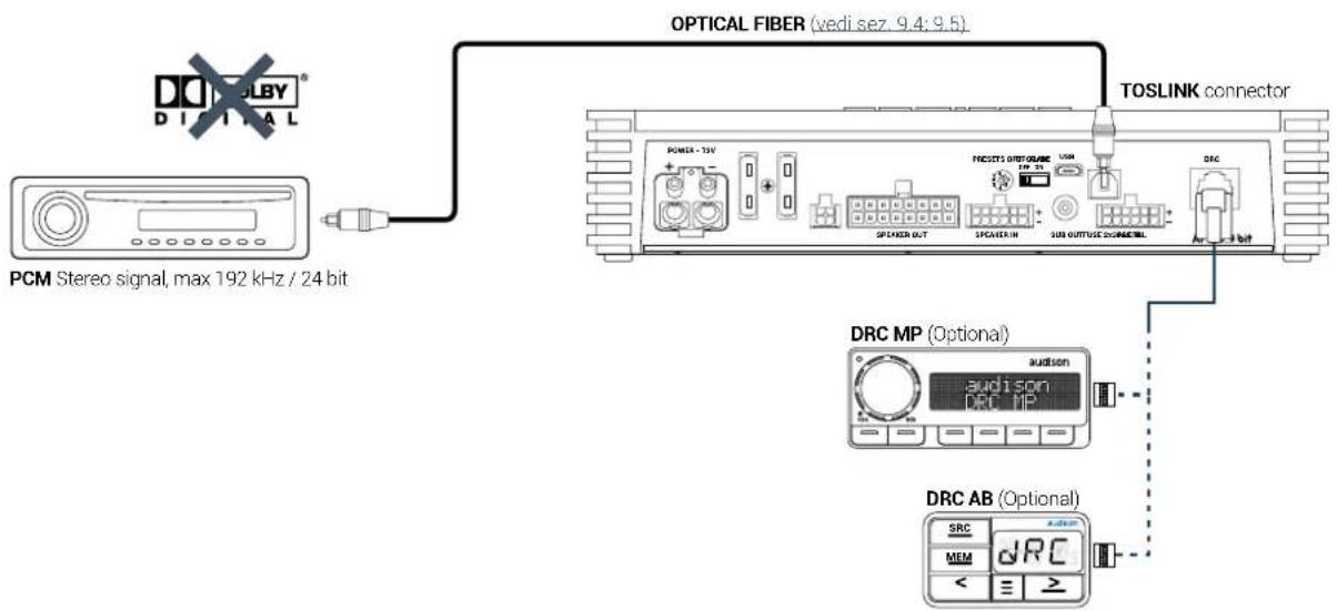
WARNING: the digital input accepts up to 192 kHz / 24 bit stereo PCM signals. So DOLBY DIGITAL (AC3) multi-channel signals coming from audio/video sources (such as the audio of a film in DVD) or DTS can not be reproduced. The output of these devices will therefore have to be set in STEREO mode for the signal to be reproduced.
How to select the OPTICAL input:
- Using the DRC, selecting the OPTICAL input.
- Using the OPTICAL IN terminal.
This command is active connecting the terminal to +12V.
5.4 OUTPUT SIGNALS
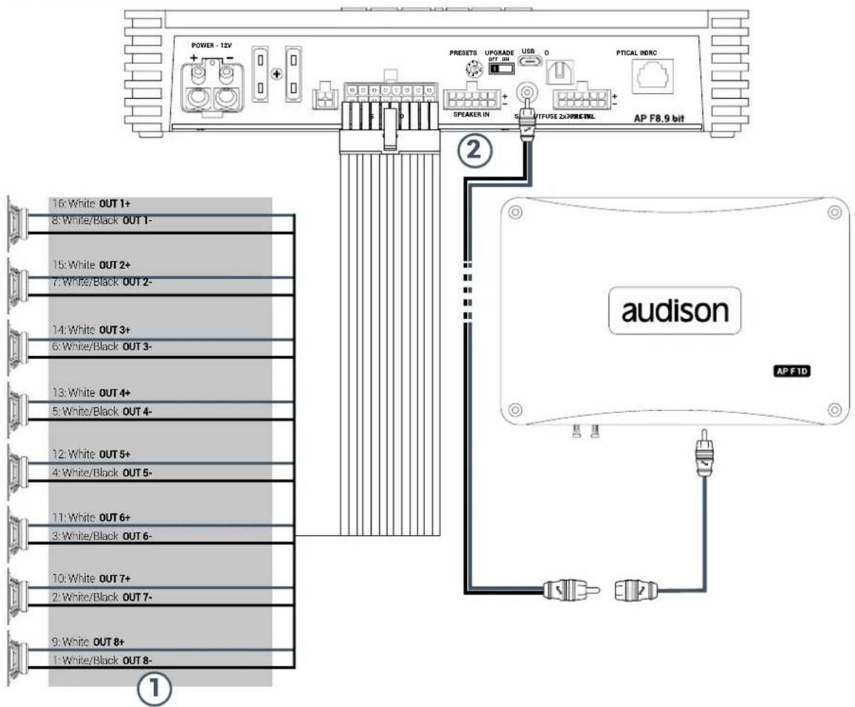
- AP F8.9 bit provides 8 amplified outputs. Through the PC Software, each output channel is provided with the
following (ee sec. 7.2):
- a 10 pole graphic equalizer;
- a 68-frequency electronic crossover and Butterworth or Linkwitz-Riley type filters with 6-24 dB slopes (see sec. 7.3.10);
- a digital time delay line (see sec. 7.3.11);
- phase inversion activation (see sec. 7.3.10.2);
- adjustment of the output level to better align the total system response (see sec. 7.3.13);
CH 1÷CH 8 AMPLIFIED OUTPUT CHANNELS CONFIGURATION
| POWER CHANNEL CONFIG | |
| STEREO MODE BRIDGE MODE | |
| CH1 85 W @ 4 Ohm / 130 W @ 2 OhmCH2 85 W @ 4 Ohm / 130 W @ 2 Ohm | CH1+ / CH2 - 260 W @ 4 Ohm |
| CH3 85 W @ 4 Ohm / 130 W @ 2 OhmCH4 85 W @ 4 Ohm / 130 W @ 2 Ohm | CH3+ / CH4 - 260 W @ 4 Ohm |
| CH5 85 W @ 4 Ohm / 130 W @ 2 OhmCH6 85 W @ 4 Ohm / 130 W @ 2 Ohm | CH5+ / CH6 - 260 W @ 4 Ohm |
| CH7 85 W @ 4 Ohm / 130 W @ 2 OhmCH8 85 W @ 4 Ohm / 130 W @ 2 Ohm | CH7+ / CH8 - 260 W @ 4 Ohm |
- AP F8.9 bit features a preamplified output (4 V Rms max.) SUB OUT that exclusively controls a mono amplifier for subwoofer, or one active subwoofer to amplify the sound system. This output can be activated during I/O Wizard Configuration (see sec. 7.2.9).
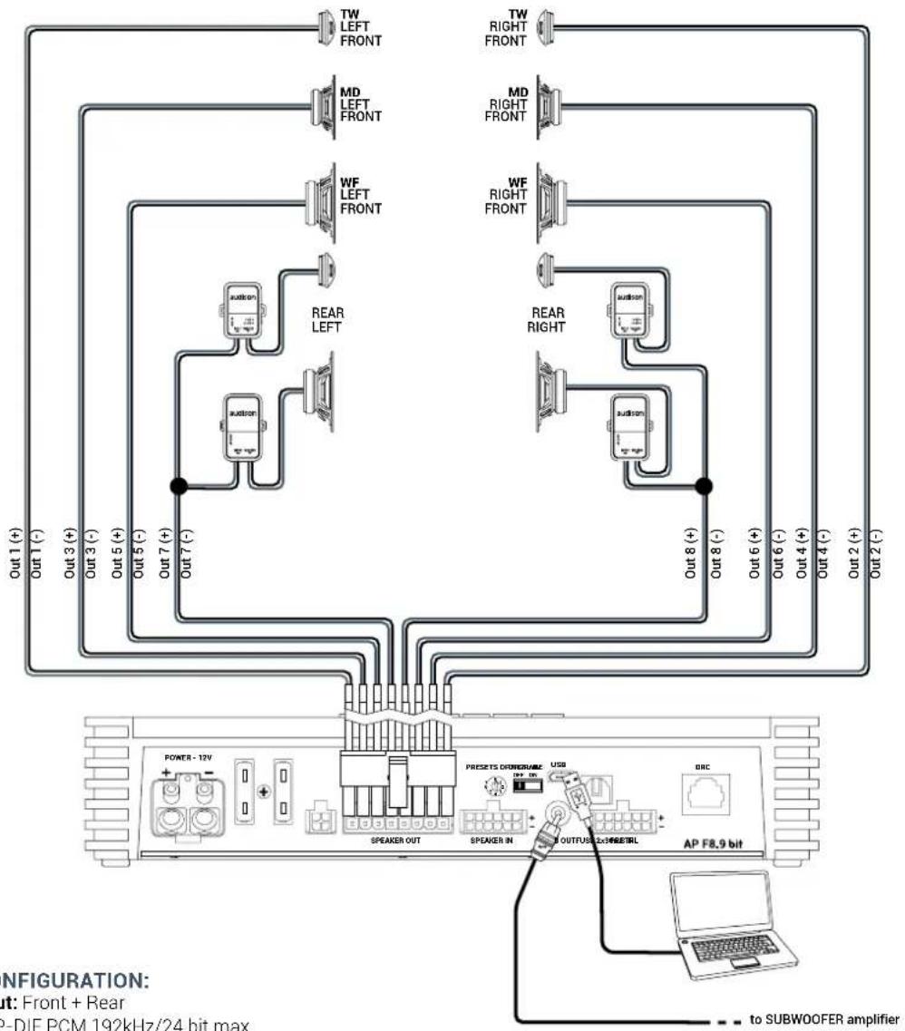
5.4.1 PRESET 0 DEFAULT: 3 WAY ACTIVE FRONT + REAR + EXTERNAL SUBWOOFER

flowchart
graph TD
    subgraph Left_Signaling
        direction TB
        A["TW LEFT FRONT"] --> B["MD LEFT FRONT"]
        C["WF LEFT FRONT"] --> D["REAR LEFT"]
        E["AUDSON"] --> F["REAR RIGHT"]
    end
    subgraph Right_Signaling
        direction TB
        G["MD RIGHT FRONT"] --> H["WF RIGHT FRONT"]
        I["AUDSON"] --> J["REAR RIGHT"]
    end
    K["AP F8.9 bit"] --> L["TO SUBWOOFER amplifier"]
    M["POWER - 12V"] --> N["SPEAKER OUT"]
    O["PRESSETS DIMENSIONS"] --> P["USB"]
    Q["OUTFUS 2.0/46/57/58"] --> R["UP"]
    S["UP"] --> T["USB"]
    U["UP"] --> V["USB"]
    W["UP"] --> X["USB"]
    Y["UP"] --> Z["USB"]
    AA["UP"] --> AB["USB"]
    AC["UP"] --> AD["USB"]
    AE["UP"] --> AF["USB"]
    AG["UP"] --> AH["USB"]
    AI["UP"] --> AJ["USB"]
    AK["UP"] --> AL["USB"]
    AM["UP"] --> AN["USB"]
    AO["UP"] --> AP["UP"]
    AQ["UP"] --> AR["USB"]
    AS["UP"] --> AT["USB"]
    AU["UP"] --> AV["USB"]
    AW["UP"] --> AX["USB"]
    AY["Out 1 (+)"] --> AZ
    BA["Out 3 (+)"] --> BB
    BC["Out 5 (+)"] --> BD
    BE["Out 7 (+)"] --> BF
    BG["Out 8 (-)"] --> BH
    BI["Out 6 (+)"] --> BJ
    BK["Out 4 (+)"] --> BL
    BM["Out 2 (+)"] --> BN
    BO["Out 2 (-)"] --> BP
    BQ["Out 1 (-)"] --> BR
    BS["Out 3 (-)"] --> BT
    BU["Out 5 (-)"] --> BV
    BW["Out 7 (-)"] --> BX
    BY["TW RIGHT FRONT"] --> BQ
    CA["MD RIGHT FRONT"] --> BQ
    CB["WF RIGHT FRONT"] --> BQ
    CC["AUDSON"] --> BD
    DD["AUDSON"] --> BE
    DE["AUDSON"] --> BF
    EF["AUDSON"] --> BG
    BG --> BH
    BH --> BI
    BI --> BJ
    BJ --> BK
    BK --> AL
    AL --> AM
    AM --> AN
    AN --> AO
    AO --> AP
INPUT CONFIGURATION:
Master input: Front + Rear
Optical: S/P-DIF PCM 192kHz/24 bit max
OUTPUT CONFIGURATION:
| OUTPUT | TYPE | CUT FILTER | FILTER TYPE | CUT FREQUENCY | TIME ALIGNMENT* | POWER 4Ω | POWER 2Ω |
| OUT 1 | FRONT TW LEFT | HI PASS | Linkwitz | 5000 Hz @12 dB | 0 | 85 W | 130 W |
| OUT 2 | FRONT TW RIGHT | HI PASS | Linkwitz | 5000 Hz @12 dB | 0 | 85 W | 130 W |
| OUT 3 | FRONT MD LEFT | BAND PASS | Linkwitz | 500 Hz @12 dB3000 HZ @ 12 dB | 0 | 85 W | 130 W |
| OUT 4 | FRONT MD RIGHT | BAND PASS | Linkwitz | 500 Hz @12 dB3000 HZ @ 12 dB | 0 | 85 W | 130 W |
| OUT 5 | FRONT WF LEFT | BAND PASS | Linkwitz | 80 Hz @12 dB500 HZ @ 12 dB | 0 | 85 W | 130 W |
| OUT 6 | FRONT WF RIGHT | BAND PASS | Linkwitz | 80 Hz @12 dB500 HZ @ 12 dB | 0 | 85 W | 130 W |
| OUT 7 | REAR LEFT FULL | HI PASS | Linkwitz | 80 Hz @12 dB | 0 | 85 W | 130 W |
| OUT 8 | REAR RIGHT FULL | HI PASS | Linkwitz | 80 Hz @12 dB | 0 | 85 W | 130 W |
| SUB OUT | SUB WOOFER | LO PASS | Linkwitz | 80 Hz @12 dB | 0 | - | - |
5.4.2 PRESET 1: 2 WAY ACTIVE FRONT + 2 WAY PASSIVE REAR + SUBWOOFER



flowchart
graph TD
    A["Power - 12V"] --> B["SPEAKER OUT"]
    B --> C["AP F8.9 bit"]
    C --> D["USB"]
    D --> E["PRESETS OUTPUT/MAKE OFF ON"]
    E --> F["AP F8.9 bit"]
    F --> G["SPEAKER IN"]
    G --> H["SUB OUTFUSE 2x3 MHz/DTNL"]
    H --> I["DRC"]
    I --> J["Output 2 (-)"]
    J --> K["Out 7 (+)"]
    K --> L["Subwoofer"]
    L --> M["Output 8 (-)"]
    M --> N["Output 6 (+)"]
    N --> O["Output 4 (-)"]
    O --> P["Output 4 (+)"]
    P --> Q["Output 3 (+)"]
    Q --> R["Output 1 (+)"]
    R --> S["Output 5 (-)"]
    S --> T["Output 5 (+)"]
    T --> U["Output 3 (-)"]
    U --> V["Output 1 (-)"]
    V --> W["Output 1 (+)"]
INPUT CONFIGURATION:
Master input: Front + Rear
Optical: S/P-DIF PCM 192kHz/24 bit max
OUTPUT CONFIGURATION:
| OUTPUT | TYPE | CUT FILTER | FILTER TYPE | CUT FREQUENCY | TIME ALIGNMENT* | POWER 4Ω | POWER 2 Ω |
| OUT 1 | FRONT TW LEFT | HI PASS | Linkwitz | 3000 Hz @12 dB | 82,2 | 85 W | 130 W |
| OUT 2 | FRONT TW RIGHT | HI PASS | Linkwitz | 3000 Hz @12 dB | 116,2 | 85 W | 130 W |
| OUT 3 | FRONT WF LEFT | BAND PASS | Linkwitz | 80 Hz @12 dB3000 HZ @ 12 dB | 82,2 85 W | 130 W | |
| OUT 4 | FRONT WF RIGHT | BAND PASS | Linkwitz | 80 Hz @12 dB3000 HZ @ 12 dB | 116,2 | 85 W | 130 W |
| OUT 5 | REAR LEFT | HI PASS | Linkwitz | 80 Hz @12 dB | 62,3 | 85 W | 130 W |
| OUT 6 | REAR RIGHT | HI PASS | Linkwitz | 80 Hz @12 dB | 116,2 | 85 W | 130 W |
| OUT 7+ 8- | SUBWOOFER | LO PASS | Linkwitz | 80 Hz @12 dB | 121,8 | 250 W | N. A. |
MEMORY CONFIGURATION:
Memory A: Acoustic
Memory B: Rhythm
5.4.3 PRESET 2: 3 WAY ACTIVE FRONT + SUBWOOFER


INPUT CONFIGURATION:
Master input: Front + Rear
Optical: S/P-DIF PCM 192kHz/24 bit max
OUTPUT CONFIGURATION:
| OUTPUT | TYPE | CUT FILTER | FILTER TYPE | CUT FREQUENCY | TIME ALIGNMENT* | POWER 4Ω | POWER 2 Ω |
| OUT 1 | FRONT TW LEFT | HI PASS | Linkwitz | 3000 Hz @12 dB | 82,2 cm | 85 W | 130 W |
| OUT 2 | FRONT TW RIGHT | HI PASS | Linkwitz | 3000 Hz @12 dB | 116,2 cm | 85 W | 130 W |
| OUT 3 | FRONT MD LEFT | BAND PASS | Linkwitz | 500 Hz @12 dB3000 HZ @ 12 dB | 82,2 cm 85 W | 130 W | |
| OUT 4 | FRONT MD RIGHT | BAND PASS | Linkwitz | 500 Hz @12 dB3000 HZ @ 12 dB | 116,2 cm | 85 W | 130 W |
| OUT 5 | FRONT WF LEFT | BAND PASS | Linkwitz | 80 Hz @12 dB500 HZ @ 12 dB | 82,2 cm 85 W | 130 W | |
| OUT 6 | FRONT WF RIGHT | BAND PASS | Linkwitz | 80 Hz @12 dB500 HZ @ 12 dB | 116,2 cm | 85 W | 130 W |
| OUT 7+ 8- | SUBWOOFER | LO PASS | Linkwitz | 80 Hz @12 dB | 121,8 cm | 260 W | N. A. |
MEMORY CONFIGURATION:
Memory A: Acoustic
Memory B: Rhythm
5.4.4 PRESET 3: FRONT + REAR + SUBWOOFER


flowchart
graph TD
    A["Power - 12V"] --> B["Speaker OUT"]
    B --> C["AP F8.9 bit"]
    D["FRONT LEFT"] --> E["Speaker OUT"]
    E --> F["AP F8.9 bit"]
    G["FRONT RIGHT"] --> H["Speaker OUT"]
    H --> I["AP F8.9 bit"]
    J["REAR LEFT"] --> K["Speaker OUT"]
    K --> L["AP F8.9 bit"]
    M["REAR RIGHT"] --> N["Speaker OUT"]
    N --> O["AP F8.9 bit"]
    P["SUBWOOFER"] --> Q["Speaker OUT"]
    Q --> R["AP F8.9 bit"]
    S["OUT 1 (+)"] --> T["OUT 2 (-)"]
    T --> U["OUT 5 (+)"]
    V["OUT 7 (+)"] --> W["OUT 8 (-)"]
    X["OUT 6 (+)"] --> Y["OUT 3 (+)"]
    Z["OUT 4 (-)"] --> AA["OUT 4 (+)"]
INPUT CONFIGURATION:
Master input: Front + Rear
Optical: S/P-DIF PCM 192kHz/24 bit max
OUTPUT CONFIGURATION:
| OUTPUT | TYPE | CUT FILTER | FILTER TYPE | CUT FREQUENCY | TIME ALIGNMENT* | POWER 4Ω | POWER 2Ω |
| OUT 1 + 2- | FRONT LEFT | HI PASS Linkwitz 80 Hz @12 dB 82,2 cm 260 W N. A. | |||||
| OUT 3 + 4- | FRONT RIGHT | HI PASS | Linkwitz | 80 Hz @12 dB | 116,2 cm | 260 W | N. A. |
| OUT 5 | REAR LEFT | HI PASS | Linkwitz | 80 Hz @12 dB | 62,3 cm | 85 W | 130 W |
| OUT 6 | REAR RIGHT | HI PASS | Linkwitz | 80 Hz @12 dB | 116,2 cm | 85 W | 130 W |
| OUT 7 + 8- | SUBWOOFER | LO PASS | Linkwitz | 80 Hz @12 dB | 121,8 cm | 260 W | N. A. |
MEMORY CONFIGURATION:
Memory A: Acoustic
Memory B: Rhythm
5.4.5 PRESET 4: 2 WAY ACTIVE FRONT + REAR + SUB



flowchart
graph TD
    A["Power - 12V"] --> B["Speaker OUT"]
    B --> C["AP F8.9 bit"]
    D["Speaker IN"] --> E["PRESCTS ORTHORAME USB"]
    E --> F["SUBOUTFUSE 2X CONNECTIL"]
    G["Speaker OUT"] --> H["SPEAKER OUT"]
    I["Speaker IN"] --> J["SPEAKER OUT"]
    K["Speaker OUT"] --> L["SPEAKER OUT"]
    M["Speaker OUT"] --> N["SPEAKER OUT"]
    O["Speaker OUT"] --> P["SPEAKER OUT"]
    Q["Speaker OUT"] --> R["SPEAKER OUT"]
    S["Speaker OUT"] --> T["SPEAKER OUT"]
    U["Speaker OUT"] --> V["SPEAKER OUT"]
    W["Speaker OUT"] --> X["SPEAKER OUT"]
    Y["Speaker OUT"] --> Z["SPEAKER OUT"]
    AA["Speaker OUT"] --> AB["SPEAKER OUT"]
    AC["Speaker OUT"] --> AD["SPEAKER OUT"]
    AE["Speaker OUT"] --> AF["SPEAKER OUT"]
    AG["Speaker OUT"] --> AH["SPEAKER OUT"]
    AI["Speaker OUT"] --> AJ["SPEAKER OUT"]
    AK["Speaker OUT"] --> AL["SPEAKER OUT"]
    AM["Speaker OUT"] --> AN["SPEAKER OUT"]
    AO["Speaker OUT"] --> AP["SPEAKER OUT"]
    AQ["Speaker OUT"] --> AR["SPEAKER OUT"]
    AS["Speaker OUT"] --> AT["SPEAKER OUT"]
    AU["Speaker OUT"] --> AV["SPEAKER OUT"]
    AW["Speaker OUT"] --> AX["SPEAKER OUT"]
    AY["Speaker OUT"] --> AZ["SPEAKER OUT"]
    BAZ["Speaker OUT"] --> BB["SPEAKER OUT"]
    BCX["Speaker OUT"] --> BD["SPEAKER OUT"]
    BEX["Speaker OUT"] --> BF["SPEAKER OUT"]
    BGXD["Speaker OUT"] --> BH["SPEAKER OUT"]
    BIYX["Speaker OUT"] --> BJ["SPEAKER OUT"]
    BKXY["XW LEFT FRONT"] --> BL["MD LEFT FRONT"]
    BL --> BM["MD RIGHT FRONT"]
    BM --> BN["MD LEFT FRONT"]
    BOX["XW LEFT FRONT"] --> BP["MD LEFT FRONT"]
    BP --> BQ["MD RIGHT FRONT"]
    BX["XW LEFT FRONT"] --> BY["MD LEFT FRONT"]
    BZ["XW LEFT FRONT"] --> CA["MD LEFT FRONT"]
    CB["XW LEFT FRONT"] --> CC["MD LEFT FRONT"]
    DD["XW LEFT FRONT"] --> DE["MD LEFT FRONT"]
    EY["XW LEFT FRONT"] --> EF["MD LEFT FRONT"]
    GF["XW LEFT FRONT"] --> GH["MD LEFT FRONT"]
    BIYX["XW LEFT FRONT"] --> BIYX["XW LEFT FRONT"]
INPUT CONFIGURATION:
Master input: Front + Rear
Optical: S/P-DIF PCM 192kHz/24 bit max
OUTPUT CONFIGURATION:
| OUTPUT | TYPE | CUT FILTER | FILTER TYPE | CUT FREQUENCY | TIME ALIGNMENT* | POWER 4Ω | POWER 2Ω |
| OUT 1 | FRONT MD TW LEFT | HI PASS | Linkwitz | 500 Hz @12 dB | 82,2 cm | 85 W | 130 W |
| OUT 2 | FRONT MD TW RIGHT | HI PASS | Linkwitz | 500 Hz @12 dB | 116,2 cm | 85 W | 130 W |
| OUT 3 | FRONT WF LEFT | BAND PASS | Linkwitz | 80 Hz @12 dB500 HZ @ 12 dB | 82,2 cm | 85 W | 130 W |
| OUT 4 | FRONT WF RIGHT | BAND PASS | Linkwitz | 80 Hz @12 dB500 HZ @ 12 dB | 116,2 cm | 85 W | 130 W |
| OUT 5 | REAR LEFT | HI PASS | Linkwitz | 80 Hz @12 dB | 62,3 cm | 85 W | 130 W |
| OUT 6 | REAR RIGHT | HI PASS | Linkwitz | 80 Hz @12 dB | 116,2 cm | 85 W | 130 W |
| OUT 7 + 8- | SUBWOOFER | LC PASS | Linkwitz | 80 Hz @12 dB | 121,8 cm | 260 W | N.A. |
MEMORY CONFIGURATION:
Memory A: Acoustic
Memory B: Rhythm
*Listening Point: Driver
5.4.6 PRESET 5: 3 WAY ACTIVE FRONT + REAR + EXTERNAL AMPLIFIED SUB


flowchart
graph TD
    subgraph Top_Layer
        A["TW LEFT FRONT"] --> B["MD LEFT FRONT"]
        C["MD RIGHT FRONT"] --> D["WF LEFT FRONT"]
        E["RF"] --> F["REAR LEFT"]
        G["RF"] --> H["SUBWOOFER"]
        I["RF"] --> J["REAR RIGHT"]
    end
    subgraph Bottom_Layer
        K["POWER - 12V"] --> L["Speaker OUT"]
        M["PHISETS OUT MAX"] --> N["Speaker IN"]
        O["USB"] --> P["UPFUSE 2x3/RESET"]
        Q["DRC"] --> R["AP F8.9 bit"]
    end
    style Top_Layer fill:#f9f,stroke:#333
    style Bottom_Layer fill:#ccf,stroke:#333
    note right of Top_Layer
        **out: Front + Rear**;        **out: AP-DIF PCM 192kHz/24 bit max**; text at bottom left;
        **out 1 (+) to Out 7 (-)**
        note right of Bottom_Layer
        **out 1 (-) to Out 7 (+)**
        note right of Bottom_Layer
        **out 2 (-) to Out 7 (-)**
        note right of Bottom_Layer
        **out 3 (-) to Out 7 (+)**
        note right of Bottom_Layer
        **out 4 (-) to Out 7 (+)**
        note right of Bottom_Layer
        **out 5 (-) to Out 7 (+)**
        note right of Bottom_Layer
        **out 6 (-) to Out 7 (-)**
        note right of Bottom_Layer
        **out 7 (-) to Out 7 (+)**
        note right of Bottom_Layer
        **out 8 (+) to Out 8 (-)**
        note right of Bottom_Layer
        **out 8 (-) to Out 8 (+)**
        note right of Bottom_Layer
        **out 1 (+) to Out 1 (-)**
        note right of Bottom_Layer
    end
INPUT CONFIGURATION:
Master input: Front + Rear
Optical: S/P-DIF PCM 192kHz/24 bit max
OUTPUT CONFIGURATION:
| OUTPUT | TYPE | CUT FILTER | FILTER TYPE | CUT FREQUENCY | TIME ALIGNMENT* | POWER 4Ω | POWER 2Ω |
| OUT 1 | FRONT TW LEFT | HI PASS | Linkwitz | 3000 Hz @12 dB | 82,2 cm | 85 W | 130 W |
| OUT 2 | FRONT TW RIGHT | HI PASS | Linkwitz | 3000 Hz @12 dB | 116,2 cm | 85 W | 130 W |
| OUT 3 | FRONT MD LEFT | BAND PASS | Linkwitz | 500 Hz @12 dB3000 Hz @ 12 dB | 82,2 cm | 85 W 130 W | |
| OUT 4 | FRONT MD RIGHT | BAND PASS | Linkwitz | 500 Hz @12 dB3000 Hz @ 12 dB | 116,2 cm | 85 W 130 W | |
| OUT 5 | FRONT WF LEFT | BAND PASS | Linkwitz | 80 Hz @12 dB500 HZ @ 12 dB | 82,2 cm | 85 W 130 W | |
| OUT 6 | FRONT WF RIGHT | BAND PASS | Linkwitz | 80 Hz @12 dB500 HZ @ 12 dB | 116,2 cm | 85 W 130 W | |
| OUT 7 | REAR LEFT | HI PASS | Linkwitz | 80 Hz @12 dB | 62,3 cm | 85 W | 130 W |
| OUT 8 | REAR RIGHT | HI PASS | Linkwitz | 80 Hz @12 dB | 116,2 cm | 85 W | 130 W |
| SUB OUT | SUB WOOFER | LO PASS | Linkwitz | 80 Hz @12 dB | 121,8 cm | - | - |
MEMORY CONFIGURATION:
Memory A: Acoustic
Memory B: Rhythm
*Listening Point: Driver
5.4.7 PRESET 6: 2 WAY ACTIVE FRONT + REAR + EXTERNAL AMPLIFIED SUB



flowchart
graph TD
    A["Power - 12V"] --> B["Speaker OUT"]
    B --> C["Speaker IN"]
    C --> D["AP F8.9 bit"]
    D --> E["audison"]
    E --> F["Output"]

    subgraph Input
        G["TW LEFT FRONT"] --> H["RF"]
        I["WF LEFT FRONT"] --> J["RF"]
        K["REAR LEFT"] --> L["RF"]
        M["REAR RIGHT"] --> N["RF"]
    end

    subgraph Output
        O["Out 1 (-)"] --> P["OUT 3 (+)"]
        Q["Out 4 (-)"] --> R["Out 7 (+)"]
        S["Out 8 (-)"] --> T["Out 2 (-)"]
    end

    U["Subwoofer"] --> V["RF"]
    W["PRESSETS ORIOMIDE USB"] --> X["RF"]
    Y["UPF 2x300MHz"] --> Z["AP"]
    style A fill:#f9f,stroke:#333
    style E fill:#ccf,stroke:#333
    style F fill:#cfc,stroke:#333
    style G fill:#fcc,stroke:#333
    style H fill:#cff,stroke:#333
    style I fill:#ffc,stroke:#333
    style J fill:#ffc,stroke:#333
    style K fill:#ffc,stroke:#333
    style L fill:#ffc,stroke:#333
    style M fill:#ffc,stroke:#333
    style N fill:#ffc,stroke:#333
    style O fill:#ffc,stroke:#333
    style P fill:#ffc,stroke:#333
    style Q fill:#ffc,stroke:#333
    style R fill:#ffc,stroke:#333
    style S fill:#ffc,stroke:#333
    style T fill:#ffc,stroke:#333
    style U fill:#ffc,stroke:#333
    style V fill:#ffc,stroke:#333
    style W fill:#ffc,stroke:#333
    style X fill:#ffc,stroke:#333
    style Y fill:#ffc,stroke:#333
    style Z fill:#ffc,stroke:#333
INPUT CONFIGURATION:
Master input: Front + Rear
Optical: S/P-DIF PCM 192kHz/24 bit max
OUTPUT CONFIGURATION:
| OUTPUT | TYPE | CUT FILTER | FILTER TYPE | CUT FREQUENCY | TIME ALIGNMENT* | POWER 4 Ω | POWER 2 Ω |
| OUT 1 | FRONT TW LEFT | HI PASS | Linkwitz | 3000 Hz @12 dB | 82,2 cm | 85 W | 130 W |
| OUT 2 | FRONT TW RIGHT | HI PASS | Linkwitz | 3000 Hz @12 dB | 116,2 cm | 85 W | 130 W |
| OUT 3 + 4- | FRONT WF LEFT | BAND PASS | Linkwitz | 80 Hz @12 dB3000 HZ @ 12 dB | 82,2 cm | 260 W N. A. | |
| OUT 5 + 6- | FRONT WF RIGHT | BAND PASS | Linkwitz | 80 Hz @12 dB3000 HZ @ 12 dB | 116,2 cm | 260 W | N. A. |
| OUT 7 | REAR LEFT | HI PASS | Linkwitz | 80 Hz @12 dB | 62,3 cm | 85 W | 130 W |
| OUT 8 | REAR RIGHT | HI PASS | Linkwitz | 80 Hz @12 dB | 116,2 cm | 85 W | 130 W |
| SUB OUT | SUBWOOFER | LO PASS | Linkwitz | 80 Hz @12 dB | 121,8 cm | - | - |
MEMORY CONFIGURATION:
Memory A: Acoustic
Memory B: Rhythm
5.4.8 PRESET 7: 2 WAY ACTIVE FRONT + REAR + 2 WAY CENTER CHANNEL + EXTERNAL AMPLIFIED SUB

flowchart
graph TD
    A["POWER - 12V"] --> B["SPEAKER OUT"]
    B --> C["PRESETS ORDERABLE OFF ON"]
    C --> D["USB"]
    D --> E["DRC"]
    E --> F["AP F8.9 bit"]
    F --> G["audison"]
    G --> H["OUT 6 (+)"]
    H --> I["OUT 4 (+)"]
    I --> J["OUT 2 (-)"]
    J --> K["OUT 2 (-)"]
    K --> L["OUT 5 (+)"]
    L --> M["REAR FULL LEFT"]
    M --> N["suider"]
    N --> O["RF"]
    O --> P["RF"]
    P --> Q["RF"]
    Q --> R["RF"]
    R --> S["RF"]
    S --> T["RF"]
    T --> U["RF"]
    U --> V["RF"]
    V --> W["RF"]
    W --> X["RF"]
    X --> Y["RF"]
    Y --> Z["RF"]
    Z --> AA["RF"]
    AA --> AB["RF"]
    AB --> AC["RF"]
    AC --> AD["RF"]
    AD --> AE["RF"]
    AE --> AF["RF"]
    AF --> AG["RF"]
    AG --> AH["RF"]
    AH --> AI["RF"]
    AI --> AJ["RF"]
    AJ --> AK["RF"]
    AK --> AL["RF"]
    AL --> AM["RF"]
    AM --> AN["RF"]
    AN --> AO["RF"]
    AO --> AP["RF"]
    AP --> AQ["RF"]
    AQ --> AR["RF"]
    AR --> AS["RF"]
    AS --> AT["RF"]
    AT --> AU["RF"]
    AU --> AV["RF"]
    AV --> AW["RF"]
    AW --> AX["RF"]
    AX --> AY["RF"]
    AY --> AZ["RF"]
    AZ --> BA["RF"]
    BA --> BB["RF"]
    BB --> BC["RF"]
    BC --> BD["RF"]
    BD --> BE["RF"]
    BE --> BF["RF"]
    BF --> BG["RF"]
    BG --> BH["RF"]
    BH --> BI["RF"]
    BI --> BJ["RF"]
    BJ --> BK["RF"]
    BK --> BL["RF"]
    BL --> BM["RF"]
    BM --> BN["RF"]
    BN --> BO["RF"]
    BO --> BP["RF"]
    BP --> BQ["RF"]
    BQ --> BR["RF"]
    BR --> BS["RF"]
    BS --> BT["RF"]
    BT --> BU["RF"]
    BU --> BV["RF"]
    BV --> BW["RF"]
    BW --> BX["RF"]
    BX --> BY["RF"]
INPUT CONFIGURATION:
Master input: Front + Rear
Aux input: In1 + In 2
Optical: S/P-DIF PCM 192kHz/24 bit max
OUTPUT CONFIGURATION:
| OUTPUT | TYPE | CUT FILTER | FILTER TYPE | CUT FREQUENCY | TIME ALIGNMENT* | POWER 4 Ω | POWER 2 Ω |
| OUT 1 | FRONT TW LEFT | HI PASS | Linkwitz | 3000 Hz @12 dB | 82,2 cm | 85 W | 130 W |
| OUT 2 | FRONT TW RIGHT | HI PASS | Linkwitz | 3000 Hz @12 dB | 116,2 cm | 85 W | 130 W |
| OUT 3 | FRONT WF LEFT | BAND PASS | Linkwitz | 80 Hz @12 dB3000 HZ @ 12 dB | 82,2 cm | 85 W | 130 W |
| OUT 4 | FRONT WF RIGHT | BAND PASS | Linkwitz | 80 Hz @12 dB3000 HZ @ 12 dB | 116,2 cm | 85 W | 130 W |
| OUT 5 | REAR LEFT | HI PASS | Linkwitz | 80 Hz @12 dB | 62,32 cm | 85 W | 130 W |
| OUT 6 | REAR RIGHT | HI PASS | Linkwitz | 80 Hz @12 dB | 116,2 cm | 85 W | 130 W |
| OUT 7 | CENTER TW | HI PASS | Linkwitz | 300 Hz @12 dB | 79,3 cm | 85 W | 130 W |
| OUT 8 | CENTER WF | BAND PASS | Linkwitz | 300 Hz @12 dB3000 HZ @ 12 dB | 79,3 cm | 85 W | 130 W |
| SUB OUT | SUB WOOFER | LO PASS | Linkwitz | 80 Hz @12 dB | 121,8 cm | - | - |
MEMORY CONFIGURATION:
Memory A: Acoustic
Memory B: Rhythm
*Listening Point: Driver
5.5 PC CONNECTION AND DIGITAL REMOTE CONTROL (DRC)
1. AP F8.9 bit connection with PC

6. GUIDE FOR INSTALLING/UNINSTALLING AP F8.9 bit SOFTWARE AND DRIVERS
6.1 GUIDED PROCEDURE FOR PC SOFTWARE INSTALLATION
- Insert the "AP F8.9 bit Setup CD 1.0" in the drive on the PC you wish to use.
- Windows Vista: access Computer from the Windows START menu;
Windows 7: access Computer from the Windows START menu;
Windows 8 / 10: access the Desktop from Windows 8 MAIN menu;

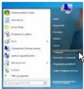
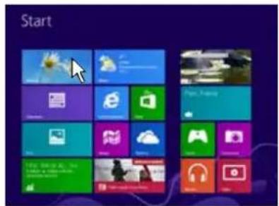
Windows Vista Windows 7 Windows 8 / 10
- Windows Vista: right click on the icon for the "AP F8.9 bit Setup CD 1.0" and click on Explore;
Windows 7: right click on the icon for the "AP F8.9 bit Setup CD 1.0" and click on Open;
Windows 8 / 10: access Computer from the Windows 8 menu;

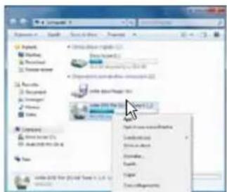

natural_image
Close-up of white daisies with yellow centers against a blue sky background (no text or symbols)Windows Vista Windows 7 Windows 8 / 10
- Windows Vista: double click on the setup icon;
Windows 7: double click on the setup icon;
Windows 8 / 10: select the CD drive and double click on the setup icon;

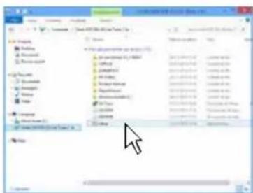
Windows Vista Windows 7 Windows 8 / 10
Remark: to remove any restrictions on Windows Vista 7/8/10 operating systems, right-click on the setup icon and select the option "Run as Administrator". Then select Yes to continue with the installation from the next window "User Account Control".
- Windows Vista: select I AGREE to continue with the installation or CANCEL to interrupt it; Windows 7: select I AGREE to continue with the installation or CANCEL to interrupt it; Windows 8 / 10: select I AGREE to continue with the installation or CANCEL to interrupt it;

- Windows Vista: select INSTALL on the tab;
Windows 7: select INSTALL on the tab;
Windows 8 / 10: select INSTALL on the tab;
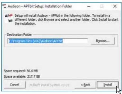
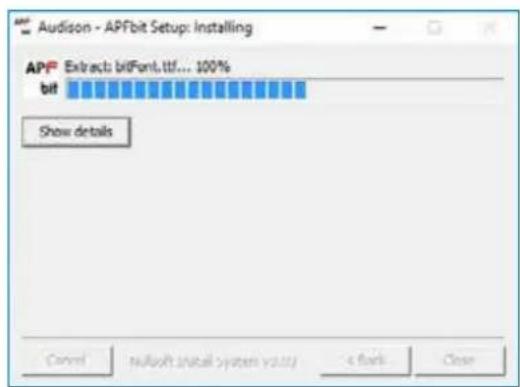
- Windows Vista: follow and complete the installation procedure and click CLOSE at the end of the installation; Windows 7: follow and complete the installation procedure and click CLOSE at the end of the installation; Windows 8 / 10: follow and complete the installation procedure and click CLOSE at the end of the installation;

6.2 GUIDED PROCEDURE FOR DRIVER INSTALLATION
- Turn on AP F8.9 bit
- Connect the USB cable on the connector on AP F8.9 bit to a free USB port on the PC.
WARNING: when connecting a laptop via USB to AP F8.9 bit while it is turned on, the laptop has to work with its own battery and stay disconnected from the mains adapter (external power supply). Once the connection between the laptop and AP F8.9 bit has been established, you can immediately connect the computer, if necessary, to the mains adapter.
- Windows Vista: the PC will recognize AP F8.9 bit interface and installation will start automatically;

Windows 7: the PC will recognize AP F8.9 bit interface and installation will start automatically;

Windows 8 / 10: the PC will recognize AP F8.9 bit interface and installation will start automatically;
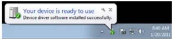
- The peripheral device has been installed correctly and is ready for use.
*Remark: AP F8.9 bit uses the HID drivers already built into Windows. For this reason, they are not included on the CD and will always install automatically.
6.3 UNINSTALLING AP F8.9 bit SOFTWARE
Procedure 1
To uninstall AP F8.9 bit PC software you can use the link in the menu:
Start / All programs / AP F8.9 bit / uninstall
Procedure 2
To uninstall AP F8.9 bit PC software, you can also use the standard procedure:
Start / Control Panel / Uninstall or change a program / AP F8.9 bit / remove.

7. HOW TO SET UP AP F8.9 BIT WITH A PC
7.1 OFFLINE MODE
OFFLINE mode can be used to analyze the software without connecting AP F8.9 bit to the PC to become familiar with the numerous functions of the processor. (For specific functions, see TARGET mode section 7.2). To activate the OFFLINE mode, the device must be disconnected from the PC. The software is preset to start with a 3 way active FRONT + REAR full multi-amplified system. To set a new "virtual" system and thus change the inputs and select the outputs, select the function Configuration Wizard in the SETTINGS window of the software main menu.
![audison File Memories Settings Device Help SELECT CHANNEL solo 0dB 0dB 0dB 0dB 0dB 0dB 0dB 0dB 0dB link -20 -20 -20 -20 -20 -20 -20 -20 -40 -40 -40 -40 -40 -40 -40 -40 0.0 0.0 0.0 0.0 0.0 0.0 0.0 DRC 0dB 0dB -15 -3 -30 -6 -45 -9 -60 -12 -50.0 0.0 vol sub Memory A Memory B Master Optical male Ch 1 Ch 2 Ch 3 Ch 4 Ch 5 Ch 6 Ch 7 Ch 8 Filter type Filter model High Pass Butterworth Hi-P Hz Lo-P Hz 6000 Hi-P slope Lo-P slope 24 Set distance Delay Fine set 0.0 0.0 0.0 0.0 in cm ms ms Invert phase XOver L/R link Flat 5MHz 100Hz 500Hz 1kHz 5kHz 10kHz G = L/4dB Fc = 20000.0Hz BW = [15171A, 20000.0Hz] Sensitivity Limiter Basic-Boost De-IQ Mode EXP](/content/2026/05/876263/images/ab532000faa04f18e342b7c780354cc210d7bdb4a5cb93940a619809537b68e9.jpg)
Remark: Change the size of the window for the PC software.
- To make the window full-screen, click on the Enlarge button or double click on the title bar of the PC Software window.
- To restore the previous size from full-screen, click on the Reset button or double click on the title bar on the window.
- To resize the PC Software window (make it smaller or larger), position the mouse pointer on one edge or corner of the window. When the mouse pointer becomes an arrow with a double point, drag the edge or corner to make the window larger or smaller.

natural_image
Pure geometric corner lines without any text, numbers, or symbols7.2 TARGET MODE
In order to configure the inputs, amplified and pre-amplified power outputs, EQ and time delays for AP F8.9 bit, it must be interfaced with the PC. When you get to this point you must already be aware of what type of system you intend to set up. In order to change these choices at a later date, you will need to perform the guided procedure again.
The guided procedure will request:
- The type of specialization for the main input channels used. The guided procedure changes according to your choice.
- The type of signals that will be assigned to the main inputs (e.g.: Front Left or Center or Subwoofer, etc.).
- The speakers in the system (e.g.: 3 way Front or Sub Stereo or 2 way Rear, etc.).
- If there are passive crossovers that manage groups of speakers (e.g.: 3 way systems with active midrange).
- If you intend to use an external monophonic amplifier to drive a Subwoofer or an external amplified subwoofer.
- If you intend to use the amplified outputs on AP F8.9 bit in BRIDGE configuration, thus increasing the power on the output.
WARNING: during this operation, we recommend disconnecting the power connector from AP F8.9 bit to

-
Connect the speaker outputs or the Pre Out outputs from the INPUTS on AP F8.9 bit (see sec. 4.2). Before turning on the system, make sure the power outputs are disconnected from AP F8.9 bit to avoid damaging the speakers during calibration.
The input calibration operation must be performed with the vehicle engine running. In this case, the voltage is about 14.0 V. The source will provide an undistorted output signal at higher volume. -
Turn on AP F8.9 bit and connect the USB cable to the PC. Start AP F8.9 bit software by clicking on the icon on the PC Desktop that was created upon installation.

- If synchronization is successful, a communication window will appear that shows the data exchange between the processor and software. Wait a few seconds.

bar
Read settings from device... | Category | Value (%) | |---|---| | Green Segment | 0 | | White Segment | 19 |- Click on the Settings menu and select Configuration Wizard.
Press Start to continue with the configuration.
Press Cancel to exit the procedure.

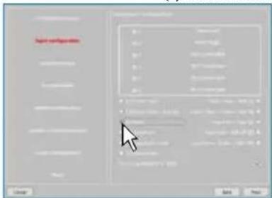
5. Input Configuration
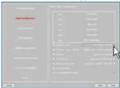
Any of the input channels on AP8.9 bit can be given the name corresponding to the signal coming from the source. Choose one of the following input configurations:
- (1) Front + Rear: controls Front stereo + Rear stereo. It is possible to select from the drop-down menu which input sections to use to drive the subwoofer in the audio system. The subwoofer channel /s can be driven either by the input signal coming from the Front line, or by the input signal coming from the Rear line or by the one coming from the mix of Front+Rear lines.
- (2) Front + Rear + SUB: controls Front stereo + Rear stereo + Subwoofer mono.
- (3) Front + Rear + SUB L/R: controls Front stereo + Rear stereo + SUB stereo;
- (4) Front + Rear + Center + SUB: controls Front stereo + Rear stereo + Center + SUB mono;
- (5) Front: controls Front stereo.
- (6) 2 WAY Front + Rear: controls a 2 way active Front stereo + Rear. It is possible to select from the drop-down menu which input sections to use to drive the subwoofer in the audio system. The subwoofer channel /s can be driven either by the input signal coming from the Front line, or by the input signal coming from the Rear line or by the one coming from the mix of Front+Rear lines;
- (7) 2 WAY Front: controls a 2 way active Front stereo;
- (8) 2 WAY Front + SUB L/R: controls a 2 way active Front stereo + SUB stereo;
- (9) 2 WAY Front + SUB: controls a 2 way active Front stereo + SUB mono;
- (10) 2 WAY Front + Center + SUB: controls a 2 way active Front stereo + Center + SUB stereo;
- (11) 3 WAY Front: controls a 3 way active Front stereo;
(1) F + R + AUX

(4) F + R + SUB

(7) 2 WAY F + AUX

(10) 2 WAY Front + Center + SUB

(2) 2 WAY F + R
(5) F + R + C + SUB
(8) 2 WAY F + SUB L/R

(11) 3 WAY Front

(3) F + R + SUB L/R

(6) F + AUX

(9) 2 WAY F + SUB L/R

AP F8.9 bit will use these names to reconstruct a full band signal coming from an OEM source with a dedicated multichannel amplifier and to assign the corresponding signal to the respective output.
Press BACK to return to the previous step.
Press NEXT to continue with the configuration.
Press CANCEL to exit the procedure.
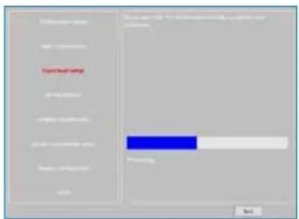
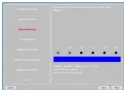
6. Input Level Setup.
- Play track 1 from the CD provided with AP F8.9 bit.
Remark: if the head unit used is not equipped with a CD player, and only features a USB input, follow the instructions below.
1) Copy the tracks in Wave format from the CD to the USB storage device.
2) Copy the tracks in mp3 format from the folder in the setup CD to the USB storage device, in case the first player is not suitable to reproduce Wav formats.
- Set all tone controls to zero (flat).
- Set balance and fader to center.
- Adjust the head unit volume to the maximum undistorted output level.
- If the head unit provides an adjustable equalizer, make sure that the controls are set to zero (flat).
Select:
- 0dB Reference: setup related to the use of music tracks recorded at 0dB.
- Musical setup: for the use of music tracks recorded at a level lower than 0dB (-3dB ÷ -6dB).
Press BACK to return to the previous step.
Press GO to continue with the configuration.
Press CANCEL to exit the procedure.
Press SKIP to skip the level calibration procedure

The input level calibration procedure is a delicate operation and must be performed very carefully. If not performed correctly, it can nullify the final sound results.
WARNING: the head unit level must be adjusted to the maximum undistorted level. If the initial head unit distortion level can not be determined, adjust the volume to approximately 80% of its maximum. If the head unit output level is set too low, the device may produce ground noise (hissing sound) when playing music tracks.
This is due to the low signal / noise ratio provided by the head unit to the AP F8.9 bit input. If you experience this problem, after calibrating the amplifiers sensitivity levels, increase the head unit volume and repeat the AP F8.9 bit calibration procedure as detailed in point 9 of this paragraph.
Head units output level instrument check
The maximum output voltage and maximum undistorted level can be measured using the Audison bit Tune SOURCE CHECK tool (see sec. 7.1 bit Tune Advanced Manual).
7. De-equalization.
De-equalization of the OEM source, operation not required and not necessary if using low level inputs (Pre out). During the high level input configuration procedure, this function can be used to maximize use of the OEM head units, even if they were equalized to adapt best to the acoustics of the car they are installed in. The de-equalization procedure performs an analysis of the electrical frequency response coming from the various channels on the OEM head unit and automatically applies an equalization opposite to the original one, generating a linear signal that is much more suitable to driving high quality audio systems. Regardless of the input channels used, the de-equalization will be performed by functional groups.

E.g.: Even if using Front Left Full and Front Right Full as inputs, the software will also perform the de-equalization on the Rear, Center and Subwoofer since the processor must use the signals identified as Front to also control any possible Rear, Center and Subwoofer outputs.
If you decide to perform this procedure, follow the instructions below:
- Insert the supplied Setup CD if the source used is an audio CD player;
- Play track 2 (press Play);
- Set all of the tone controls to zero (0).
- Set the balance and fader to the center (0).
- Don't change the adjusted volume previously set through the automatic input level calibration;
Press BACK to return to the previous step. Press GO to continue with the configuration. Press SKIP to abandon the procedure. Press CANCEL to exit the program.
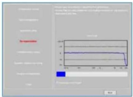
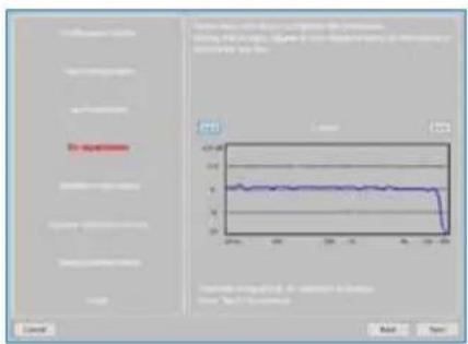
The software uses a progress bar and specific messages to show how the procedure is being executed. At the end of the procedure, the window will show the equalization curves for the head unit.
Press BACK to return to the previous step. Press NEXT to continue with the configuration. Press CANCEL to exit the program.
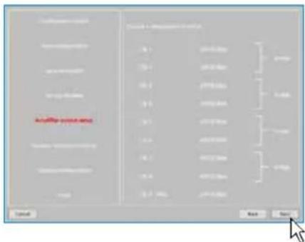
8. Amplifier Output Setup.
This window shows the configuration outline for the output signals. 8 output channels are available, which can work in "BRIDGE" mode as shown in the image.
Press BACK to return to the previous step. Press NEXT to continue with the configuration. Press CANCEL to exit the program.
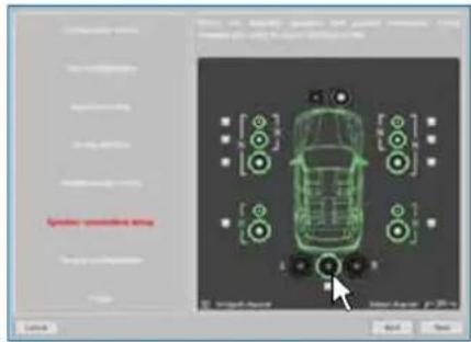
9. Speaker Connection Setup.
The speakers available in the system can be activated by simply clicking on them.
The software assumes that if the Left tweeter, midrange or woofer are selected, the Right ones are also activated. Once the software is started, this choice will affect the crossover type and frequencies with Default settings.
If passive crossover filters are not used, each speaker corresponds to an output channel.
Selection of passive crossovers for groups of speakers
The presence of passive crossovers managing functional speaker groups can be indicated.
E.g.: If the audio system features passive crossovers, the software will ask you to set them by clicking on ☑, otherwise press NEXT. A 2 or 3 way passive crossover occupies a single output channel.
If the sum of the crossovers and/or speakers exceeds the occupation of 8 PRE output channels, the software will not allow you to proceed with the next operation. Check again the configuration of the crossovers or, using BACK, the speakers setup.
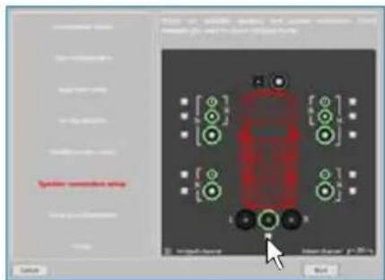
WARNING: a coaxial speaker is considered a as

Select Bridge Mode outputs for groups of speakers.
In order to increase the driving power of the speaker output, set AP F8.9 bit outputs to BRIDGE mode, selecting the check mark as indicated in the image.
Press BACK to return to the previous step.
Press NEXT to continue with the configuration.
Press CANCEL to exit the procedure.

10. Output Configurations.
AP F8.9 bit features 9 output channels. In this specific step of the procedure you can assign any signal to one of the output channels.
E.g.: The 3 way front can be controlled as:
- multi amplified (6 output channels are needed);
- passive midrange + woofer amplified separately (4 output channels are needed);
- 3 way passive (2 output channels are needed).
During the selection, the software will automatically notify that the 9 output channel limit has been respected, the warning message will disappear and the NEXT button will appear.
For convenience, if output 1 is assigned to the left Tweeter, the software will automatically assign output 2 to the right Tweeter. During the procedure, if the left midrange speakers are also assigned output 1, the software will display a warning message. Simply change the assignment of one of the two numbers in red and the software will automatically position it to the first available channel.
Press BACK to return to the previous step.
Press NEXT to continue with the configuration.
Press CANCEL to exit the procedure.
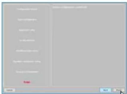
11. Finish.
Stop playing the Test track and remove the setup CD from the source player.
Press BACK to return to the previous step.
Press CANCEL to exit the procedure.
Press FINISH to end the configuration.
12. Software startup
The software transfers to the central processor memory the settings selected during the guided procedure.
At the end of this operation, an update confirmation will appear.
Press OK.
The product will now have to be finalized to avoid the data saved during calibration (see sec. 7.3.5.2). using the function FINALIZE the device.

[Non-Text]

[Non-Text]
[NO TEXT]

7.3 ADJUSTING ACOUSTIC REPRODUCTION
The following paragraphs describe the functions to adjust the system and its acoustic fine tuning.
WARNING: when exploring the functions, do not change the parameters on AP F8.9 bit. Take your time to get familiar with the possibilities the software offers.

If you choose to leave the speakers/amplifiers connected to AP F8.9 bit, remember to make adjustments with a general volume that won't damage the other speakers in the system. (see sec. 7.3.13.8)
![SELECT CHANNEL 13 solo 0dB 0dB 0dB 0dB 0dB 0dB 0dB 0dB link -20 -20 -20 -20 -20 -20 -20 -20 -40 -40 -40 -40 -40 -40 -40 -40 0.0 0.0 0.0 0.0 0.0 0.0 0.0 DRC 0dB 0dB -15 -3 30 -6 -45 -9 -60 -12 -50.0 0.0 vol sub audison APF8.9bit fw: 1.0.0.3 drc: 2.04 w device connected Memory A Memory A Master Optical 9 Ch 1 Ch 2 Ch 3 Ch 4 Ch 5 Ch 6 Ch 7 Ch 8 Filter type Model High Pass Butterworth Hi-P Hz Lo-P Hz 6000 Hi-P slope Slope 24 Set distance Delay Fine set 0.0 0.0 0.0 0.0 cm ms ms Invert phase XOver L/R link Flat Equalizer Filter Filter+EQ EQ bypass L/R link -10dB 50Hz 100Hz 500Hz 1kHz 5kHz 10kHz G = L4dB Fc = 20000.0Hz BW = [15171A, 20000.0]Hz 12 Ready Sensitivity Limiter Bass-Bond De-FO Mode DP](/content/2026/05/876263/images/35ebba08e1558d46e19bd5098953666ac6de13ba0a0ebed1fc964409a1ebc535.jpg)
7.3.1 DEVICE INFO 1
This window shows whether AP F8.9 bit is properly interfaced with the PC and the DRC. It also shows the Firmware version for the device and the Serial Number.
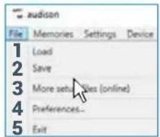
7.3.2 FILE MAIN MENU

By clicking on the File tab, a drop-down menu appears with the entries shown in the image:
- Load: it loads the entire AP F8.9 bit configuration from a previously saved file (e.g.: "AP F8.9 bit setup1.apf"). This function is present in both TARGET mode and in OFF LINE mode.
In TARGET mode it can reload all of the previously saved settings. This function is useful if you wish to install another AP F8.9 bit with the same settings.
The input level calibration and, possibly, the De-Eq levels must be repeated.
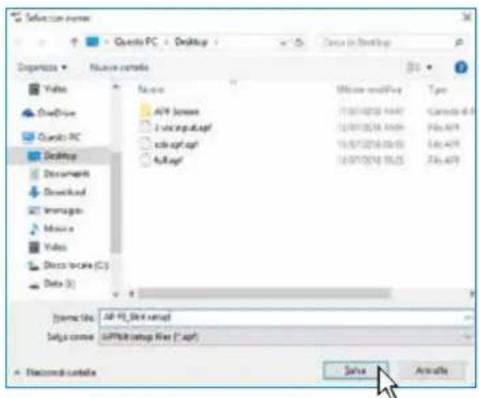
In OFF LINE mode, you can check the previously saved settings. - Save Setup: it saves the entire AP F8.9 bit configuration for AP F8.9 bit in one file (e.g.: "AP8.9Config.apf"), that can be reloaded later in AP F8.9 bit using the Load Setup function. This function is present in both TARGET mode and in OFF LINE mode.
- More setup files (online): this function requires an internet connection. By clicking on this entry, a link to download new installation setups appears.
- Preferences: it lets you display the context messages in the chosen "Language" (Italian or English). The PC Software automatically defaults to English. To change the language, select language from the menu and restart the PC Software.
Remark: other languages may also be available. Verify through "Check for Updates"
- Exit: exits the PC software.
7.3.3 MEMORIES MAIN MENU

By clicking on this item, a drop-down menu appears with the entries shown in the image:
- Copy A to B: to copy the contents of memory A to memory B.
- Copy B to A: to copy the contents of memory B to memory A.
- Reset current memories: to reset the crossover and standard equalizer values, those that are proposed at the end of the configuration procedure.
- Load memory from file: to load a previously saved memory, by placing it in one of the two available memories.



Load A to A Load A to B Load B to A Load B to B
7.3.4 SETTINGS MAIN MENU

By clicking on this item, a drop-down menu appears with the entries shown in the image:
- I/O Configuration Wizard: it sets up the system, and puts AP F8.9 bit in the conditions needed to be able to perform this operation (see sec. 7.2).
WARNING: whenever performing the I/O Configuration Wizard, the values set in the Options menu (see sec. 7.3.4.7) are set to the default values.

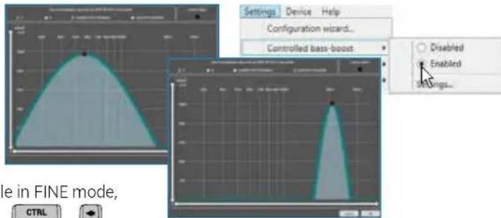
- Controlled bass-boost: if enabled, through this function you can operate on the equalization of the sub channel and woofers. By clicking on Settings you can choose the parametric equalizer pole where you can operate and vary the "Q" factor by acting on the mouse wheel when available or using the keys "and" on the PC keyboard.
Remark: to select the frequency parametric pole in FINE mode, use the PC keyboard keys " + " CTRL
When heavy equalization is set, the software will activate through soft clipping eliminating the subsequent distortions. This function can also be enabled and disabled via DRC MP. (see sec. 9.1).
-
Limiter: by selecting "Enabled" the limiter of the AP F8.9 output signal will be activated. This function is essential to prevent temporary clipping phenomena, that lead to the outputs saturation. By selecting "disabled" the function will be deactivated. By default the limiter id disabled.
-
De-Equalizer: if activated (Enabled), this function enables the de-equalization curve calculated during the Configuration Wizard. If the function is deactivated (Disabled) no source de-equalization curve is applied.
The Reset command deletes the de-equalization curve calculated during the Configuration Wizard.

- Working Mode: the software can work in two modes, acting on the crossover filter section.
Standard: simplified mode with some restrictions easing the use of the software (see sec. 7.3.10).
Expert: there are no restrictions in the software functions of use (see sec. 7.3.10).
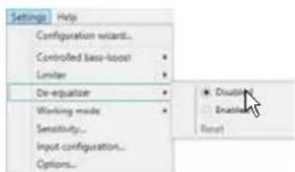
WARNING: switching from one mode to another resets the configuration of the filters to their original Default setting.

- Sensitivity: lets you display and adjust the sensitivity of AP F8.9 bit inputs. To perform the sensitivity calibration, refer to sec. 7.2.6.

- Input configuration: shows the specialization assigned to the inputs on AP F8.9 bit during the Configuration wizard.

- Options: by clicking on this item, a drop-down menu appears with the entries shown in the image:
Signals: lets you set how AP F8.9 bit is turned on through:
- Turn ON by SPEAKER DC (ART): when Enabled is selected, AP F8.9 bit can be turned on through the amplified output (BTL) of a source connected to the inputs FL-FR-RL-RR. This function can be disabled by selecting Disabled.

- Turning ON by SIGNAL PRESENCE (AST): when Enabled is selected, AP F8.9 bit can be turned on through the presence of a signal from a amplified source connected to the inputs IN1, IN2, IN3, IN4, IN5, IN6. The stand-by time (energy saver) for the device when there is no signal can be set through the function TIMES -> SLEEP time out for analog input (see next point). The shut down time for the device when there is no signal is set to 30 mins. This function can be disabled by selecting Disabled.
Times: Lets you change the settings for the times to turn AP F8.9 bit on and off.
- Remote OUT delay (sec): this is the delay between disabling of the REMOTE OUT signal to the amplifiers and turning off AP F8.9 bit. It is not usually necessary to change this parameter but it may be useful to decrease it whenever there are amplifiers that produce a turn off "Bump".
- MUTE release delay (sec): this is the delay between turning on the device and the activation of the output audio. Each amplifier has a turn on phase, its own delay before being operational. Setting Startup Time to a value equal to or greater than the longest delay will provide synchronized audio startup for the whole system.
- SLEEP timeout for analog input (min): it sets the amplifier's stand-by time when there is no audio signal. The stand-by time (energy saver) can be set from 1 min minimum to 20 mins maximum. Normal operation is resumed when the audio signal is present. This function is set on 20 minutes by default and can be enabled by selecting the desired amount of minutes.
The SLEEP timeout for analog input function allows to save power and provides the ability for the product to work at lower temperatures.
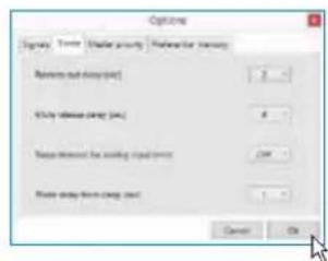
Remark: we recommend that the shortest possible activation time is selected in case of hybrid or electric propulsion cars; it won't affect the product normal operation.
- Wake delay from sleep (sec): it sets the amplifier resume delay from energy saver status. The delay time can be adjusted from a minimum of 0 sec. to a maximum of 5 secs. This function is set by default at 0 secs (disabled).
Remark: some factory (OEM) head units are provided with a control signal lasting approx. 2 secs during the turn-on phase to check if loudspeakers are in the system (see section 4.3). If the head unit is turned off while the car is being used, the AP F8.9 bit, if turned on through ART, will keep working to let the security alerts, phone alerts, navigation system alerts etc. be reproduced. When the head unit is turned on again, the speaker presence control alerts may be reproduced. To avoid this happens, you can set the Wake delay from sleep (sec) duration at a value slightly higher than the duration of the speaker presence control alerts.
WARNING: if the car is equipped with security alerts, phone alerts, navigation system alerts, ...etc., if you set a too long Wake delay from sleep (sec), reproduction of the first part of the mentioned signals might be missed.

Master priority: it allows the user to modify the audio signal level settings.
- MASTER ENABLE attenuation: sets the signal level for the master input when enabled from the terminal
"MASTER ENABLE".
You can choose the activation levels between 0 dB and -18 dB

Preferential memory: it enables the association of a memory to the single inputs.

7.3.5 DEVICE MAIN MENU

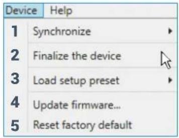
By clicking on this item, a drop-down menu appears with the entries shown in the image:
- Synchronize: this function synchronizes the PC with AP F8.9 bit and vice versa due to communication losses caused by the device shutting down or for other reasons.
Read from Device: the PC loads the settings present in AP F8.9 bit memory to the PC Software.
Write to device: the PC loads the current settings to AP F8.9 bit memory.
- Finalize the device: it lets you load all of the parameters set during system calibration in the internal memory, letting the AP F8.9 bit operate without being connected to the PC.
When Finalize to AP F8.9 bit is performed, the software gives a warning that the previously saved data in AP F8.9 bit will be overwritten.
- Click on YES to load the data.
-
Click on NO to interrupt the procedure.
-
Load setup preset: it loads one of the 7 "PRESETS" in the AP F8.9 bit preset 0 memory, to be editable (see sec. 5.4.2 - 5.4.8).
- Update firmware: this allows firmware updates on AP F8.9 bit (see sec. 8.3).
- Reset factory default: performs full reset of AP F8.9 bit returning the product to its original conditions, deleting all previously saved data from the processor memory.

bar
| Category | Green Segment (%) | White Segment (%) | |---|---|---| | Best settings from device... | 12 | 0 | | Write settings to device... | 43 | 0 |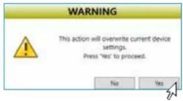


7.3.6 HELP MAIN MENU

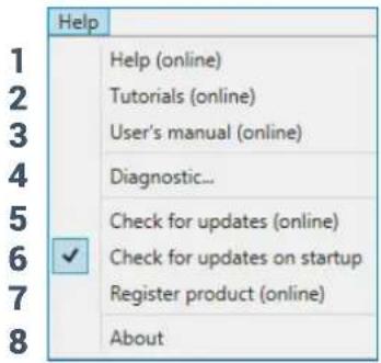
By clicking on this item, a drop-down menu appears with the entries shown in the image:
1) Help (online): this function requires an internet connection. By activating this function and moving the mouse pointer to the various sections of the graphic interface for the PC software, the concerned area will be highlighted in red. By clicking on the red area, a link will activate, opening up the default browser, displaying the paragraph of the manual related to that specific area. The manual will be displayed in the language selected in FILE->PREFERENCES (see sec. 7.3.2)


2) Tutorials (online): this function requires an internet connection. Clicking on this item activates a youtube link to consult audio/video information regarding the product.
3) User's Manual (online): the internet browser installed in your PC will open up and a research for the URL www.audisonbitdrive.eu will automatically start, offering the possibility to check the product manual online.
4) Diagnostic: this function is to use exclusively if requested by the Audison authorized service centre. It generates a file named "xxxxxxxxxxx.dng" that is saved on the PC desktop, to diagnose the product. This function is useful to fix installation issues remotely.
5) Check for Updates: connects to the website www.audisonbitrive.eu and checks for updates to the AP F8.9 bit Software/Firmware in order to be able to update the device in use (see sec. 8.3). To perform this operation, the PC must have an active internet connection.
6) Check for Updates on startup: when enabled the availability of new firmware/PC Software updates is checked automatically each time you start the program.
7) Register product: this function requires an internet connection and opens the default browser to the page for registering the product and creating a personal account in the "bit Drive" portal. This operation only needs to be performed once; then you can access your account through the Login Account.
8) About: shows information regarding AP F8.9 bit software in use.
7.3.7 SELECTED INPUT

The "Selected Input" window shows the active source during connection with the PC. This can be used to select the desired source. Once disconnected from the PC, you can select the input source through the DRC (see sec. 9) or through the external functions "MASTER ENABLE" and "OPTICAL ENABLE".
7.3.8 CHANNEL MAP

This window shows the name attributed to the output channels. The window is active. You can click on it to manage the individual channel that, once selected, will be highlighted. If you hold down the CTRL key and click on another channel, it will also be selected and highlighted. At the same time, the filter curve will appear on the graph area. Multiple selection is only allowed for functional groups, except for the Subwoofer, which can be selected together with any group.
E.g.: Front Left Full together with Subwoofer, but not with Rear Left Full.


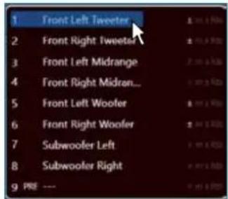
If you wish to check the electrical response of the Rear system together with the Subwoofer, you must clear the Front system selection. However, the software will only let you operate on a single channel and will show the message "EDIT" in red to the side of the channel that you can operate on. More specifically, the graph will show the electrical responses from the only crossover related to the channel being edited in red. The overall electrical response from all channels selected will be shown in yellow, taking into account the crossover filters and equalizations. The final result will be shown in green.

To act on another channel without losing the selection, simply click to the right of the desired channel in the EDIT column. The CHANNEL MAP window also lets you mute the individual channels by clicking on MUTE to the left of the desired channel.
If MUTE is active on the channel, "m" is shown in red.
If the SOLO function is active, "s" is shown in green.
If there are time delays on the channel, "fds" is shown in yellow. A channel can also be selected as shown in the outline in the image (see sec. 7.3.9).
7.3.9 SELECT CHANNEL 9
This window is enabled. You can click directly on the speaker or speaker system to be able to display or set the parameters for the individual channel. Once selected, the speaker(s) will be highlighted.
If you hold down the CTRL key and click on another channel, it will also be selected and highlighted as occurs with the "Channel Map"
(see sec. 7.3.8). Listening point visual indicator.
This window includes the position indicator (in red).
There are four preset points: driver, passenger, front center and rear center for passengers.
The indication only acts as a reference, allowing you to display the listening points for which the digital display calculation was optimized (see sec.7.3.11). If you set the delays in relation to the "driver" position and then you wish to also optimize the system for the "passenger" position, you must reset the distances in the specific menu since the system does not update them automatically.
If used together with the presets (see sec. 7.3.14) it is useful to try different setups according to the different listening points.

7.3.10 FILTER SETTINGS 10
AP F8.9 bit manages nine crossover filters, one for each output channel. Each filter allows you to set the parameters of a single output channel.
- Xover L/R Link: it lets you transfer the adjustments made on the Right channel to the Left one and vice versa. To activate it, you must click on the blue light, which will come on. Xover L/R Link acts on all of the adjustments of the Filter Settings except for Set Distance (Delay).
- Invert Phase: inverts the phase of the channel under examination by 180°. This can be done by selecting the green light which will turn on. This can be useful to solve phase alignment problems among the different filtered channels.
-
Filter Type: it lets you select the type of filter to assign to the channels:
-
Full Range
- Low Pass
- High Pass
- Band Pass

In STANDARD mode:
Depending on the speaker or speaker system selected during configuration, a suitable type of filter will be available.
E.g.: For the Front Woofer, only Low Pass or Band Pass will be available. For Front Mid-Hi, only High Pass and Band Pass will be available, etc.
In EXPERT mode:
Any speaker system selected has any type of filter available.
WARNING: in EXPERT mode, pay careful attention to the filter selection. Speakers have mechanical limits that must not be exceeded, otherwise it could lead to permanent damage.
When a filter is selected, some optimized cut-off frequencies are set by default to avoid breaking the speakers.
E.g.: If you select Low Pass for a tweeter, the default frequency is suitable for a woofer but not for the tweeter, which could be damaged.
STANDARD MODE
| FILTER TYPE -> | Full Range | Low Pass | High Pass | Band Pass |
| Tweeter | X | X | ||
| Midrange | X | |||
| Woofer | X | X | ||
| Mid-Hi | X | X | ||
| Subwoofer | X | X | ||
| Full | X X X X |
EXPERT MODE
| FILTER TYPE -> | Full Range | Low Pass | High Pass | Band Pass |
| Tweeter | X X X X | |||
| Midrange | X X X X | |||
| Woofer | X X X X | |||
| Mid-Hi | X X X X | |||
| Subwoofer | X X X X | |||
| Full | X X X X |
-
Filter Model: lets you select the type of filter to be applied.
-
Linkwitz (default)
- Butterworth
When launching AP F8.9 bit software, Linkwitz is proposed as the filter model for the speaker or speaker group connected to the related channel. To apply the opposite (Left/Right), enable the Xover L/R Link. If you change the model to Butterworth, the change will be applied.

5. Cut-off frequencies
- Hi-P Hz 10 ÷ 20000: High-Pass filter
- Lo-P Hz 10 ÷ 20000: Low-Pass filter
If you select the Band-Pass filter, both the
Hi-P Hz and the Lo-P Hz boxes will be enabled to be able to set the band frequency.
You can select the cut-off frequency by:
- clicking on the related drop-down menu, selecting the frequency range that includes the value to be set and then clicking on the actual value.
- clicking on the related drop-down menu, selecting the pre-chosen frequency range and then moving from value to value using the arrow keys (up / down) on the PC keyboard.
- clicking twice on the related drop-down menu and then moving from value to value by scrolling with the mouse.

6. Filter slope
- Hi-P Slope 12/24 dB/Oct. (Linkwitz) 6/12/18/24dB/Oct (Butterworth)
- Lo-P Slope 12/24 dB/Oct. (Linkwitz) 6/12/18/24 dB/Oct (Butterworth) When starting the AP F8.9 bit software, it offers Linkwitz with 12 dB/Oct. slope.
E.g.: If you select Band Pass as the filter type, the same slope will be applied to both the hi-pass and low-pass as the default slope, but they can also be unbound.
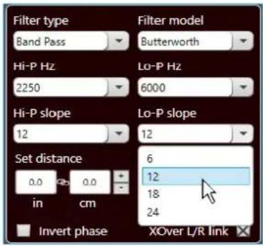
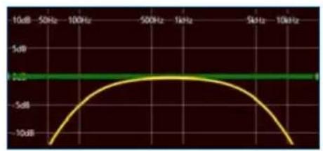
The crossover filter response related to the selected channel is displayed graphically by a yellow curve, as shown in the examples below.
E.g. Band Pass
line
| Frequency (Hz) | Amplitude (dB) | |---|---| | -50Hz | -10 | | -50Hz | -5 | | -50Hz | 0 | | -50Hz | 5 | | 10kHz | -5 | | 10kHz | 0 | | 10kHz | 5 |Crossover Frequency 80 - 2000 Hz @ 12 dB Oct. Crossover Frequency 80 Hz @ 6 dB Oct. Hi-pass

line
| Frequency | Value | |---|---| | 10dB | -15 | | 50Hz | -8 | | 100Hz | -4 | | 500Hz | -2 | | 1kHz | -1 | | 5kHz | -1 | | 10kHz | -35 |2000 Hz @ 24 dB Oct. Low-pass

line
| Frequency (Hz) | Amplitude (dB) | |---|---| | 50Hz | -10 | | 100Hz | 5 | | 500Hz | 5 | | 1kHz | 5 | | 5kHz | 5 | | 10kHz | -10 |Crossover Frequency 80 - 2000 Hz @ 24 dB Oct. Crossover Frequency 80 Hz @ 24 dB Oct. Hi-pass

line
| Frequency (Hz) | Amplitude (dB) | |---|---| | -500 | ~-12 | | -1000 | ~8 | | -5000 | ~9 | | 1000 | ~9 | | 5000 | ~9 | | 1kHz | ~9 | | 5kHz | ~7 | | 1kHz | ~4 | | 1kHz | ~1 |2000 Hz @ 6 dB Oct. Low-pass
7.3.11 SET DISTANCE AND DELAY

This setting is based on an automatic system that calculates the time needed for the sound to get from the speaker to the listener's ear.
Preliminary remarks
Sound moves through the air at a speed of 343 m/sec (1.125 ft/sec.) at a temperature of 20^ C ( 68^ F). If you know the distance from the sound emission point, you can then calculate the time the sound takes to get to the listener's ear.
If you set the distances of the different speakers, AP F8.9 bit will automatically change them into time (ms - milliseconds). It does not assign a delay (0.0 ms) to the farthest speaker (usually the Subwoofer) and progressively growing delays as much as the other speakers get closer to the listening point, in order for all the emission points to reach the listening point at the same time.
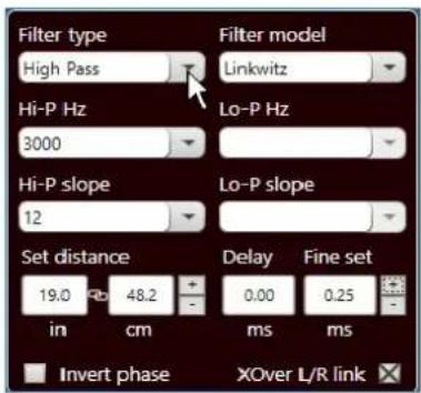
SET DISTANCE
Lets you set the distance between the speaker and the listening point. Choose cm (centimeters) or in (inches). The "Set Distance" boxes can be set using the cursors.
DELAY ms/default
Displays the time in ms (milliseconds) calculated according to the distance.
DELAY ms/fine set
AP F8.9 bit time delay calculation system also lets you perform manual fine tuning.
Preliminary remarks
Fine set and Phase delay
Delay assignment according to distance calculation is theoretical.
Small variations must be applied due to small errors in distance measurement, back-wave reflections inside the car and, primarily, the speaker phase problem.
Two speakers reproducing two frequency areas that are close to each other (e.g.: Woofer and Midrange) will simultaneously reproduce the same frequencies in their crossing area, at a attenuated level. Due to the different nature of the speakers, they will have a phase difference that, for a short frequency interval, acts as a time delay.
By using "fine set", you can partly correct these Phase Delay problems.
By using the "fine set" button, you can change the automatically set delay time.
The delay is increased (+x.xx) or decreased (-x.xx) by the delay value shown in the window "Delay/default" and does not change the value shown, which is the one that is automatically assigned.
Assigning a positive value (+x.xx) using "fine delay" means increasing the delay for that speaker and thus moving it farther away from the listening point.
Likewise, assigning a negative value (-x.xx) means decreasing the speaker delay and thus moving it closer to the listening point.
In order for you to see how much "fine Set" has been manually changed, both delay values are shown. To see the resulting delay, physically applied to the output, you have to add the values shown in the "Delay / Default" and
"Delay / Fine Set" boxes. A negative value (decreasing the delay) can not be assigned to the farthest speaker; it can only be assigned to the other speakers as they are all already delayed compared to the farthest one. If you attempt to give the farthest speaker a negative value, a warning message will appear (Fig. 1).
When using "fine set" "fds" will appear in green on the corresponding channel on the "Channel Map" (Fig. 2).

(Fig.1)

(Fig.2)
Example of setting the time delay (Fig. 3):
- Choose the system listening point.
To identify the listening point, choose an ideal spot in the center of the listener's head (driver or passenger).
For the front center and rear center, choose a point between the two listeners. - Measure the distance in a straight line from each speaker or group of speakers compared to the listening point. For each speaker, choose the center of the mobile membrane as the emission point. For groups of speakers, choose a point between them. It will then be possible to fine tune it using the Fine Set function.
- On the Channel Map, select the channel related to the speaker under examination and enter the respective distance in the Set Distance box in the Filter Settings menu.
- Repeat step 3 for each channel.

(Fig.3)
-
Once the time delay settings are complete, start the musical reproduction and use the Fine Set box, moving the values up or down (except for the subwoofer since it is the farthest speaker) to fine tune the system for optimal sound. We recommend listening to various types of music (percussion, melodic, etc.) for better evaluation of the coherence (spatial stability) of the different musical instruments.
-
Once the time alignment procedure is complete, you can work on the output equalizer (see sec. 7.3.12) to optimize the system response based on the level alignment of the various frequencies.
Remark: measurements for the above operations can also be taken using a spectrum analyzer with a suitable microphone. The results must be evaluated and optimized through listening tests.
WARNING: if, once you have set the distances for the "driver" listening point, you click on the "passenger" listening point,

AP F8.9 bit won't re-calculate the delays for the new reference because the buttons available in the SELECT CHANNEL
diagram are merely descriptive. Their only purpose is to remind you that you have set the delays for that listening point!

The AP F8.9 bit software provides an equalizer, that can be managed from a maximum of 10 graphic control points which automatically place a maximum of 10 parametric equalization points. The quantity of graphic control points used doesn't match the parametric poles quantity, which is determined by the adapting software.
The equalizer works according to the functional groups and so we have the following factory configuration:
- one equalizer for the Front Tweeter.
- one equalizer for the Front Mid
- one equalizer for the Front Woofer.
- one equalizer for the Rear.
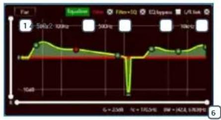
line
| Time (s) | Value | | -------- | ----- | | 50Hz | 200Hz | | 100Hz | 500Hz | | 150Hz | 100Hz |To be able to change the parameters for the equalizer in order to set an equalization curve, just choose the channel to equalize from the "Channel Map" menu, positioning the mouse over the point to be set, and shape the curve using the left mouse button (green curve), or with the arrow keys "☐ for the P keyboard.
Remark: to select the frequency parametric pole in FINE mode,
use the PC keyboard keys "CTRL + " or "CTRL + ".
In order to vary the "Q" factor of the equalization point selected, just scroll using the mouse wheel featuring this function or using the keys "⊕" and "−" on the PC keyboard.
In order to delete the changes, just put the mouse over the point, select it with the left button and press CANC on the PC keyboard.
The equalizer has specific functions that aid in calibration and make it easier.
1 Flat brings all the cursors back to the 0 dB position;
L/R Link, when active, applies the equalization curve to both the right and left channel simultaneously.
EQ by Pass , when active, lets you disable the equalizer to check its effect without losing its settings.
4 Filter lets you display the electrical response subject to filtering (XOVER), by clicking on the box (red curve).
Filter + Eq lets you display the electrical response subject to equalization, by clicking on the box (yellow curve).
Parametric poles parameters this window is active when the user wants to adjust a parametric pole. The following parameters are listed:
-Fc: parametric pole operating frequency (Fmin 20Hz ÷ Fmax 20KHz).
-G: parametric pole gain (G min +12dB ÷ Gmax -12dB).
-Bw: bandwidth of the parametric pole applied (Bw min 100Hz ÷ BWmax 4800Hz).
To prevent the display of this window just press the ESC key from the PC keyboard.
Remark: In order to clearly display the set equalization curve, you can increase or decrease the vertical axis (dB) and horizontal axis (Hz) by moving the cursors to the side of them. The default is set to +12 dB and 0-20 kHz.

line
| Time | Show sum | HQ hyper | |------|----------|-----------| | 0 | 0 | 0 | | 30 | 2 | 1 | | 60 | 3 | 2 | | 90 | 2 | 1 | | 120 | 1 | 0 | | 150 | 2 | 1 | | 180 | 3 | 2 | | 210 | 2 | 1 | | 240 | 1 | 0 | | 270 | 2 | 1 | | 300 | 3 | 2 |
line
| Time | Equinone | Mao+EQ | |------|----------|--------| | 4.8 | - | - |7.3.13 OUTPUT LEVEL
13
This section shows the settings related to the output levels of AP F8.9 bit channels. The description of the points shown in the figure is given below.

- Using one of the sliders for the output channels, you can adjust the output level (-40÷0 dB) for each channel. The sliders are enabled based on the output configuration.
- This part of the display shows the output level for each individual channel (-40÷0 dB), referring to the position of the Slider for the output channels.
- By clicking on the "Mute" button you can mute the corresponding output channels.
- By clicking on the "Mute" button again, the mute function will be disabled.
- By clicking on the "Link" button you can simultaneously adjust all of AP F8.9 bit output levels. By clicking on the "Link" button again, the function will be disabled.
- By clicking on the "Solo" button you can mute the output channels except for the one enabled.
- By manually clicking on the "Solo" button, the function will be disabled.
- Using the "Volume" slider you can adjust the general output level for the system (-60÷0 dB).
- Using the "Sub Volume" button you can adjust the output level of the subwoofer (-12÷0 dB), if the system features a subwoofer.
7.3.14 MEMORY
14
AP F8.9 bit controls the system configuration, operating by default on memory A but gives the option to store and recall two memories (A, B).
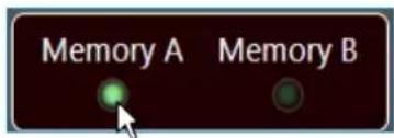
7.3.15 STATUS BAR
15
It is an information area that can be found at the bottom of the PC software window. It shows in real time the working status of AP F8.9 bit PC software.

1 Indicates the working status of AP F8.9 bit PC software.
Indicates the setup file that has been possibly loaded via PC software to the AP F8.9 bit.
3 Sensitivity: function to recall the analog Master inputs calibration, in order to refine/adjust the sensitivity. Use a music track and adjust the sensitivity until you see the LEDs starting to flash. It is possible to intervene on every single input channel or select all input channels through the LINK function.
Remark: do not overdo the sensitivity adjustment. Increasing the distortion may turn on the clipping lights and worsen the signal-to-noise ratio (background noise) of your audio system.
Limiter: When the LED is lit, that means the Bass-Boost is in operation see sec. 7.3.4.2.
5 Bass-Boost: When the LED is lit, that means the Bass-Boost is in operation see sec. 7.3.4.2.
6 De-eq: When the LED is lit, that means the de-equalization curve of the source is enabled.
7 Mode: indicates whether it is in Expert (EXP) or Standard (STD) mode see sec. 7.3.4.4.
8. TROUBLESHOOTING
8.1 SYNCHRONIZATION WITH A PC
1. AP F8.9 bit operating problems
If, when calibrating the system with AP F8.9 bit connected to a laptop there are operating problems, try disconnecting the laptop power supply cable.
With the laptop working on battery power you avoid a possible voltage difference in the USB ground between the vehicle (AP F8.9 bit) and the ground (PC).
2. Connection lost between AP F8.9 bit and the PC
If, while calibrating the system with the PC connected to AP F8.9 bit, the amplifier is turned off and back on again, the connection is lost and the software cannot finalize the adjustments that were set. To avoid losing the settings, proceed as follows:
a. Save the setup to a file on the PC using the FILE / SAVE SETUP function.
b. Exit the software.
c. Turn AP F8.9 bit on.
d. Launch the software again.
e. Load the setup file again that was saved using the FILE / LOAD SETUP function.
3. AP F8.9 bit does not respond
If calibrating the system with the PC connected to AP F8.9 bit and the latter does not respond to the commands, proceed as follows:
a. Turn off AP F8.9 bit by pressing the knob on the DRC or disconnecting the Remote IN or even disconnecting the power cable for a second.
b. Save the setup to a file on the PC using the FILE / SAVE SETUP function.
c. Exit the software.
d. TurnAP F8.9 bit on.
e. Launch the software again.
f. Load the setup file again that was saved using the FILE / LOAD SETUP function.
4. Settings not saved
To successfully complete AP F8.9 bit configuration and not lose the work done, remember to stored the settings that were made. Access the "File" menu from the management software via the PC and choose "Finalize the device".
8.2 BACKGROUND NOISE
Loud hissing/background noise.
If there is excessive hissing/background noise, it may be necessary to repeat the setup for the input sensitivity and/or correct the output level calibration. For more details see sec. 7.2.
8.3 FIRMWARE UPGRADE
If there are product UPGRADES available online, proceed as follows:
- Save the previous setup (if you wish to consult it in OFFLINE mode);
- Disconnect the "Speaker out" and "Sub out" AP F8.9 bit on.
- Set the product upgrade switch to the "ON" position
-
Turn on AP F8.9 bit. The logo will start flashing.
Start AP F8.9 bit PC Software and select TARGET mode. -
Access the "Help" menu in the PC management software and choose "Check for Updates".

- When you select "Check for Updates", the internet browser in the PC will open up and will automatically search for the URL: www.audisonbitdrive.eu.
WARNING: the files must be manually downloaded from the website.
The software access method may be different from the following. Refer to the instructions on the website.
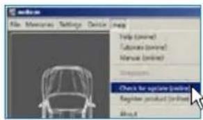
-
Once the related page is open, click on the LINK for the product.
-
Identify the newest file whose name includes the word Firmware followed by four numbers and click on the specific symbol to start the download. When requested, save the file to the PC.
-
Select "Update Firmware". The program will ask you to select the file that was just saved from the Download Area or that was previously saved in the PC.

WARNING: AP F8.9 bit Firmware update procedure may be tricky. It is of
The utmost importance that it is done under the best possible conditions. If the operation is started and prematurely interrupted (e.g.: PC locked up, loss of power to AP F8.9 bit, accidental disconnection of the USB cable during update), you might need to contact our Customer Service for further support as AP F8.9 bit may need to be reprogrammed".
-
Before starting AP F8.9 bit update, the program warns you to:
-
not disconnect AP F8.9 bit from the PC;
- not disconnect AP F8.9 bit from power;
- temporarily disable the PC automatic stand-by processes;
- temporarily disable the screen saver on the PC;
- close all running applications;
-
temporarily disable the anti-virus and anti-spyware systems.
-
Once you have clicked on OK, the Firmware update procedure starts.
This process will last between 30 seconds and 1 minute; the progress bar and the flashing logo on the AP F8.9 bit will show its the updating process status.

WARNING: during the update, the updating process of the progress bar may stop
For a few seconds. Do not interrupt the process in any way.
- When successfully completed, a notification window will appear. In order to be able to use AP F8.9 bit again, you must close the program on the PC and turn off AP F8.9 bit.
-
Set the "UPGRADE" switch to the OFF position.
-
Turn AP F8.9 bit back on and restart the PC software. If AP F8.9 bit firmware update completed correctly, the dialogue window will show:
-
new AP F8.9 bit Firmware version.
-
Repeat the product calibration operations (see sec. 7.2).

9. ACCESSORIES
9.1 DRC DIGITAL REMOTE CONTROL
9.1.1 DRC MP
The DRC MP is the digital interface between the bit processors and the user. When mounted on the vehicle's dashboard with an AP F8.9 bit processor, it will enable the following functions:
- select Master or Optical input
- control general volume, subwoofer volume, balance and fader.
- select between 2 memories pre-set by the user for the set up of equalizer and crossover alignment.
- enable/disable the Bass boost function.
- adjust the display lighting according to lighting in the car compartment.

9.1.2 DRC AB
The DRC AB is the digital interface between the bit processors and the user providing reduced functions compared to the DRC MP. When mounted on the vehicle's dashboard with an AP F8.9 bit processor, it will enable the following functions:
- select Master or Optical input
- control general volume, subwoofer volume, balance and fader.
- select between 2 memories pre-set by the user for the set up of equalizer and crossover alignment.

9.2 SPM4 (Stereo Passive Mixer 4Ch)
Stereo passive mixer (unpowered) featuring 4 input channels and 2 output channels, designed for active OEM multi-way systems where each speaker is powered by one specific amplified channel. SPM4 mixes audio through 4 audio transformers specifically developed to achieve very low distortion and highly linear acoustic response. SPM4 provides the ability to mix the midrange/woofer and tweeter channels coming from the amplifier and supply one single mid-high channel. The Ch1(L/R) channels feature two inputs, one features an inverting input compared to Ch2 (L/R) channels; the mixing process often gives better results when one of the two channels undergoes a 180° dephasing. SPM4 is especially recommended to extend the number of inputs of the Audison digital processors or amplifiers with built-in DSP because they feature a De-equalizer (De-Eq). In that case, any possible non-linear acoustic emissions due to the mixing of the pre-existing filtered channels are duly compensated.
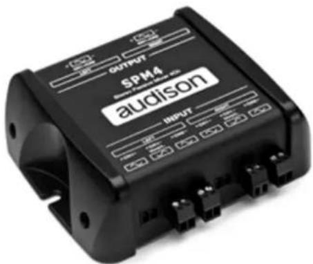
9.3 OP 1.5 TOSLINK OPTICAL CABLE 1,5 M / 59.05 IN.
Optical cable with TOSLINK connectors for S/PDIF digital audio signals.
Cable length 1.5 m / 59.05 in.

natural_image
Black cable with two connectors, no visible text or symbols9.4 OP 4.5 TOSLINK OPTICAL CABLE 4,5 M / 177.16 IN.
Optical cable with TOSLINK terminations for S/PDIF digital audio signals.
Cable length 4.5 m / 177.16 in.

natural_image
Black cable with two connectors, no visible text or symbols9.5 STA - F/F SOCKET TOSLINK ADAPTER
Optical adapter to extend optical cables with TOSLINK connectors.

10. TECHNICAL SPECIFICATIONS
POWER SUPPLY
| Power supply voltage / fuse: 11 ÷ 15 VDC / 2 x 30A |
| Operating power supply voltage: 6.5V ÷17V |
| Idling current: 1.6 A |
| Switched off without DRC: 1.7 mA |
| Switched off with DRC: 5 mA |
| Consumption @ 14.4 VDC, 2Ω, Max Musical Power: 55 A |
| Remote IN: 6 ÷15 VDC (1 mA) |
| Remote OUT: 4 ÷15 VDC (150 mA) |
| ART - Automatic Remote Turn on/off from OUTPUT BTL speakers (Selectable): |
| AST - Automatic Signal Turn on/off (Selectable): Speaker-In |
2÷7 VDC
AMPLIFIER STAGE
| Distortion - THD @ 1 kHz, 4Ω, 70% Rated Power: 0.06 % |
| Damping factor @ 1 kHz, 4Ω, 2 VRMS: > 110 |
| Bandwidth @ -1.5 dB: 10Hz ÷ 22 kHz |
| S/N ratio (A weighted @ 1 V Input) Master Input: 100 dBA |
| S/N ratio (A weighted @ 1 V Input) Optical Input: 105 dBA |
| Input sensitivity Pre-In: |
| Input sensitivity Speaker-In: |
| Minimum load impedance: 8Ch: 2Ω |
| Output power (RMS) @14.4 VDC, 1% THD: |
| • 8 Ch @ 4Ω: |
| • 8 Ch @ 2Ω: |
| • 4Ch (Bridge 1/2; 3/4; 5/6; 7/8) @ 4Ω: |
0.6 ÷ 6 VRMS
2.2÷22VRMS
4Ch - (Bridge 1/2; 3/4; 5/6; 7/8): 40
INPUTS / OUTPUTS
| Pre-In Inputs: |
| Speaker-In Inputs: |
| Digital IN: |
| Sub Out (RCA Pre Out): |
85 W × 8
130 W × 8
260 W x 4
DIGITAL SIGNAL PROCESSOR
| Filter type: |
| Filter mode and slope: |
| Crossover frequency: |
| Phase control: |
| Bass Boost |
| Analog Input Equalizer (20 ÷ 20k Hz): |
| Output Equalizer: |
| Time Alignment Distance: 0 ÷ 510 cm / 0 ÷ 200.8 inches |
| Time Alignment Delay: |
| Time Alignment Step: |
| Time Alignment Fine SET: |
| Preset (Drive Preset): |
| Acoustic Preset: |
1 x Optical S/PDIF; Max 192 kHz / 24 bit
4 VRMS
Full / Hi pass / Low Pass / Band Pass
Linkwitz @ 12/24 dB
Butterworth @ 6/12/18/24 dB
68 steps @ 20 ÷ 20k Hz
0°/180°
N.1 Adjustable Parametric Pole
Automatic De-Equalization
N.9 Parametrics Equalizers: ±12 dB; 10 pole; 20 ÷ 20k Hz
0 ÷ 15 ms
0.08 ms; 2.8 cm / 1.1 inch
0.02 ms; 0.7 cm / 0.27 inch
Rotary switch for 7 installation Presets
N.2 DSP Memory, DRC selectable
CONTROL CONNECTIONS
| From / to personal computer: |
| To Audison DRC AB / MP: |
| Optical select: |
| Master enable: |
1 x micro USB-B
1 x AC Link
Optical select wire control +12 V enable
Master enable wire control +12 V enable
GENERAL REQUIREMENTS
| PC connections: |
| Software/ PC requirements: |
| Video resolution with screen resize: |
| Ambient operating temperature range: |
Micro USB 1.1 / 2.0 / 3.0 Compatible
Microsoft Windows (32/64 bit): Vista,Win 7, Win 8, Win 10
min. 1024 x 600
0 °C to 55 °C (32 °F to 131 °F)
SIZE / WEIGHT
| Max size W x H x D (mm/inch): |
| Weight (kg/lb): |
238×49.5×155/9.37×1.95×6.1
1,98 / 4.36
audison.com
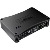

- FORZA
- AP F8.9 bit
- USER'S
- MANUAL
- Index
- PRODUCT DESCRIPTION / PRECAUTIONS
- PACKAGE CONTENTS
- AP F8.9 bit Software
- AP F8.9 bit AND DRC INSTALLATION
- CONNECTION PANELS - DESCRIPTION
- POWER.
- CTRL (REM IN-OUT / CONTROLS): terminals to turn on and control the AP F8.9bit.
- SPEAKER IN.
- PRE IN
- SPEAKER OUT.
- SUB OUT.
- OPTICAL IN.
- DRC.
- USB.
- UPGRADE OFF-ON.
- PRESET.
- FUSE.
- LOGO STATUS.
- CONNECTIONS
- Turn AP F8.9 bit on and off
- INPUT SIGNALS
- SPEAKER INPUT: FRONT + REAR
- SPEAKER INPUT: 2 WAY FRONT + REAR
- SPEAKER INPUT: FRONT + REAR + CENTER + SUB
- SPEAKER INPUT: FRONT + REAR + LEFT SUB + RIGHT SUB
- SPEAKER INPUT: 3 WAY FRONT + REAR
- PRE INPUT FRONT + REAR + CENTER + SUB + REAR
- PRE INPUT FRONT + REAR + CENTER + SUB + REAR
- DIGITAL OPTICAL IN INPUT
- How to select the OPTICAL input:
- INPUT CONFIGURATION:
- PRESET 2: 3 WAY ACTIVE FRONT + SUBWOOFER
- MEMORY CONFIGURATION:
- PRESET 3: FRONT + REAR + SUBWOOFER
- PC CONNECTION AND DIGITAL REMOTE CONTROL (DRC)
- AP F8.9 bit connection with PC
- GUIDE FOR INSTALLING/UNINSTALLING AP F8.9 bit SOFTWARE AND DRIVERS
- GUIDED PROCEDURE FOR PC SOFTWARE INSTALLATION
- GUIDED PROCEDURE FOR DRIVER INSTALLATION
- UNINSTALLING AP F8.9 bit SOFTWARE
- Procedure 1
- Procedure 2
- HOW TO SET UP AP F8.9 BIT WITH A PC
- OFFLINE MODE
- Remark: Change the size of the window for the PC software.
- TARGET MODE
- Input Configuration
- Input Level Setup.
- Head units output level instrument check
- De-equalization.
- Amplifier Output Setup.
- Speaker Connection Setup.
- Selection of passive crossovers for groups of speakers
- Select Bridge Mode outputs for groups of speakers.
- Output Configurations.
- Finish.
- Software startup
- ADJUSTING ACOUSTIC REPRODUCTION
- DEVICE INFO 1
- FILE MAIN MENU
- MEMORIES MAIN MENU
- SETTINGS MAIN MENU
- DEVICE MAIN MENU
- HELP MAIN MENU
- SELECTED INPUT
- CHANNEL MAP
- SELECT CHANNEL 9
- FILTER SETTINGS 10
- Cut-off frequencies
- Filter slope
- SET DISTANCE AND DELAY
- Preliminary remarks
- SET DISTANCE
- DELAY ms/default
- DELAY ms/fine set
- Fine set and Phase delay
- OUTPUT LEVEL
- 13
- MEMORY
- 14
- STATUS BAR
- 15
- TROUBLESHOOTING
- SYNCHRONIZATION WITH A PC
- AP F8.9 bit operating problems
- Connection lost between AP F8.9 bit and the PC
- AP F8.9 bit does not respond
- Settings not saved
- BACKGROUND NOISE
- Loud hissing/background noise.
- FIRMWARE UPGRADE
- ACCESSORIES
- DRC DIGITAL REMOTE CONTROL
- DRC MP
- DRC AB
- SPM4 (Stereo Passive Mixer 4Ch)
- OP 1.5 TOSLINK OPTICAL CABLE 1,5 M / 59.05 IN.
- OP 4.5 TOSLINK OPTICAL CABLE 4,5 M / 177.16 IN.
- STA - F/F SOCKET TOSLINK ADAPTER
- TECHNICAL SPECIFICATIONS
Brand : AUDISON
Model : Prima AP F8.9 bit
Category : Receiver