
ADP-12F/CX-A3 - Air conditioner DAITSU - Free user manual and instructions
Find the device manual for free ADP-12F/CX-A3 DAITSU in PDF.


| Product Type | Split Air Conditioner |
| Cooling Capacity | 12,000 BTU/h (approx. 3.5 kW) |
| Heating Capacity | 12,000 BTU/h (approx. 3.5 kW) with heat pump |
| Indoor Unit Dimensions (WxDxH) | 80 x 25 x 30 cm (approx.) |
| Outdoor Unit Dimensions (WxDxH) | 80 x 30 x 60 cm (approx.) |
| Indoor Unit Weight | 10 kg (approx.) |
| Outdoor Unit Weight | 30 kg (approx.) |
| Power Supply | 220-240 V ~ 50 Hz |
| Refrigerant | R32 |
| Operating Modes | Cool, Heat, Fan, Dehumidify, Auto |
| Fan Speeds | 3 (Low, Medium, High) + Auto |
| Timer | 24-hour on/off timer |
| Sleep Mode | Yes |
| Turbo Mode | Yes |
| Remote Control | Included with LCD display |
| Air Filter | Washable mesh filter |
| Filter Cleaning Reminder | Yes (indicator on unit or remote) |
| Auto Restart | Yes (after power failure) |
| Defrost Function | Yes (automatic for heating) |
| Installation | Wall-mounted indoor unit, outdoor unit on bracket or stand |
| Spare Parts Available | Remote control, filters, drain hose |
| Maintenance | Clean filter every 2 weeks; annual professional check-up recommended |
Frequently Asked Questions - ADP-12F/CX-A3 DAITSU
User questions about ADP-12F/CX-A3 DAITSU
0 question about this device. Answer the ones you know or ask your own.
Ask a new question about this device
Download the instructions for your Air conditioner in PDF format for free! Find your manual ADP-12F/CX-A3 - DAITSU and take your electronic device back in hand. On this page are published all the documents necessary for the use of your device. ADP-12F/CX-A3 by DAITSU.
USER MANUAL ADP-12F/CX-A3 DAITSU
natural_image
White electric air conditioner unit with grid and ventilation grille (no visible text or symbols)Serie
PORTABLE
Edition
R00
Models
ADP-12FX-A3
ADP-12F/CX-A3
Content
Operation Notices
The Refrigerant ....1
Safety Warning 2
Operation Environment ....3
Part's Name 4
Operation Guide
Operation Introduction for Control Panel 5
Use for air conditioner 7
Using the remote control 8
Buttons on Remote Controller 9
Introduction for Icons on Display Screen 9
Introduction for Buttons on Remote Controller 10
Function Introduction for Combination Buttons ....12
Replacement of Batteries in Remote Controller 12
Maintenance
Clean and Maintenance....13
Malfunction
Malfunction analysis ....15
Installation Notice
Installation Precaution....18
Preparation before Installation....19
Installation
Install Wire Hook 20
Removing Collected Water 21
Installation in a double-hung sash window(Optional)....24
Installation in a sliding sash window(Optional)......27
Installation and Disassembly of Heat Discharge Pipe 30
Attached Sheet
Operation Test 33
Electric Schematic Diagram....34
Specialist's Manual....35
This appliance is not intended for use by persons (including children) with reduced physical, sensory or mental capabilities, or lack of experience and knowledge, unless they have been given supervision or instruction concerning use of the appliance by a person responsible for their safety.
Children should be supervised to ensure that they do not play with the appliance.
Frequency band(s) in which the radio equipment operates: 2400MHz-2483.5MHz
Maximum radio-frequency power transmitted in the frequency band(s) in which the radio equipment operates: 20dBm
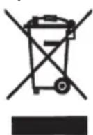
This marking indicates that this product should not be disposed with other household wastes throughout the EU. To prevent possible harm to the environment or human health from uncontrolled waste disposal, recycle it responsibly to promote the sustainable reuse of material resources. To return your used device, please use the return and collection systems or contact the retailer where the product was purchased. They can take this product for environmental safe recycling.
Explanation of Symbols

DANGER
Indicates a hazardous situation that, if not avoided, will result in death or serious injury.

WARNING
Indicates a hazardous situation that, if not avoided, could result in death or serious injury.

CAUTION
Indicates a hazardous situation that, if not avoided, may result in minor or moderate injury.


Indicates important but not hazard-related information, used to indicate risk of property damage.
Indicates a hazard that would be assigned a signal word WARNING or CAUTION.
Exception Clauses
Manufacturer will bear no responsibilities when personal injury or property loss is caused by the following reasons.
- Damage the product due to improper use or misuse of the product;
- Alter, change, maintain or use the product with other equipment without abiding by the instruction manual of manufacturer;
- After verification, the defect of product is directly caused by corrosive gas;
- After verification, defects are due to improper operation during transportation of product;
- Operate, repair, maintain the unit without abiding by instruction manual or related regulations;
- After verification, the problem or dispute is caused by the quality specification or performance of parts and components that produced by other manufacturers;
- The damage is caused by natural calamities, bad using environment or force majeure.
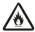
Appliance filled with flammable gas R290.

Before install and use the appliance, read the owner's manual first.

Before install the appliance, read the installation manual first.

Before repair the appliance, read the service manual first.
The Refrigerant
- To realize the function of the air conditioner unit, a special refrigerant circulates in the system. The used refrigerant is the fluoride R290, which is specially cleaned. The refrigerant is flammable and inodorous. Furthermore, it can leads to explosion under certain conditions.
- Compared to common refrigerants, R290 is a nonpolluting refrigerant with no harm to the ozonosphere. The influence upon the greenhouse effect is also lower. R290 has got very good thermodynamic features which lead to a really high energy efficiency. The units therefore need a less filling.
- Please refer to the nameplate for the charging quantity of R290.
WARNING:
• Appliance filled with flammable gas R290.
- Appliance shall be installed, operated and stored in a room with a floor area larger than 11 m ^2 .
- The appliance shall be stored in a room without continuously operating ignition sources. (for example: open flames, an operating gas appliance or an operating electric heater.)
- The appliance shall be stored in a well-ventilated area where the room size corresponds to the room area as specified for operation.
- The appliance shall be stored so as to prevent mechanical damage from occurring.
- Ducts connected to an appliance shall not contain an ignition source.
- Keep any required ventilation openings clear of obstruction.
- Do not pierce or burn.
- Be aware that refrigerants may not contain an odour.
- Do not use means to accelerate the defrosting process or to clean, other than those recommended by the manufacturer.
- Servicing shall be performed only as recommended by the manufacturer.
- Should repair be necessary, contact your nearest authorized Service Centre.
Any repairs carried out by unqualified personnel may be dangerous.
- Compliance with national gas regulations shall be observed.
- Read specialist's manual.



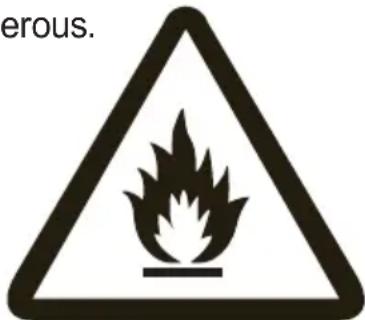
Safety Warning
- This appliance can be used by children aged from 8 years and above and persons with reduced physical, sensory or mental capabilities or lack of experience and knowledge if they have been given supervision or instruction concerning use of the appliance in a safe way and understand the hazards involved.
nerdlihc yb
without supervision. Children shall not play with the appliance.
- Before operation, please confirm whether power specification complies with that on nameplate.
- Before cleaning or maintaining the air conditioner, please turn off air conditioner and pull out the power plug.
- Make sure the power cord hasn't been pressed by hard objects.
- Do not pull or drag the power cord to pull out the power plug or move the air conditioner.
- Do not insert or pull out the power plug with wet hands.
- Please use the grounded power. Make sure the grounding is reliable.
- If the supply cord is damaged, it must be replaced by the manufacturer or its service agent or a similarly qualified person in order to avoid a hazard.
- If abnormal condition occurs (e.g. burned smell), please disconnect power at once and then contact local dealer.
- When nobody is taking care of the unit, please turn it off and remove the power plug or disconnect power.
- Do not splash or pour water on air conditioner. Otherwise, it may cause short circuit or damage to air conditioner.
- If drainage hose is used, ambient temperature can't be lower than 0.℃ Otherwise, it will cause water leakage to air conditioner.
- Prohibit operating heating equipment around the air conditioner.
- Prohibit operating the unit in the bathroom or laundry room.
- Far away from fire source, inflammable and explosive objects.
- Children and disabled people are not allowed to use the unit without supervision.
- Keep children from playing or climbing on the air conditioner.
- Do not put or hang dripping objects above the air conditioner.
- Do not repair or disassemble the air conditioner by yourself.
- Prohibit inserting any objects into the air conditioner.
- Do not through sundries into the air duct. If there are sundries get into the air duct, please contact the professionals to deal with it.
- Do not use an extension cord.
- The air conditioner must be operated within the temperature range: 16^ C 35^ C .
- The appliance is for indoor use only.
- The appliance must be positioned so that the plug is accessible.
- This air conditioner can only be used for family, not for commercial industry.
- Reserved space around the air conditioner should be 12"(30cm) at least.
- Do not operate the air conditioner at humid environment.
- Please keep air inlet and air outlet clean, no obstacles.
- During operation, close doors and windows to improve cooling effect.
- Please put the air conditioner at smooth and flat ground for operation to avoid noise and vibration.
- This air conditioner is equipped with castors. Castors should slide at smooth and flat ground.
- Prohibit inclining or turning over the air conditioner. If there's abnormality, please disconnect power immediately and contact dealer.
- Avoid direct sunshine.

Note:
Graphics in this manual are only for reference. Please refer to actual products for specific details.
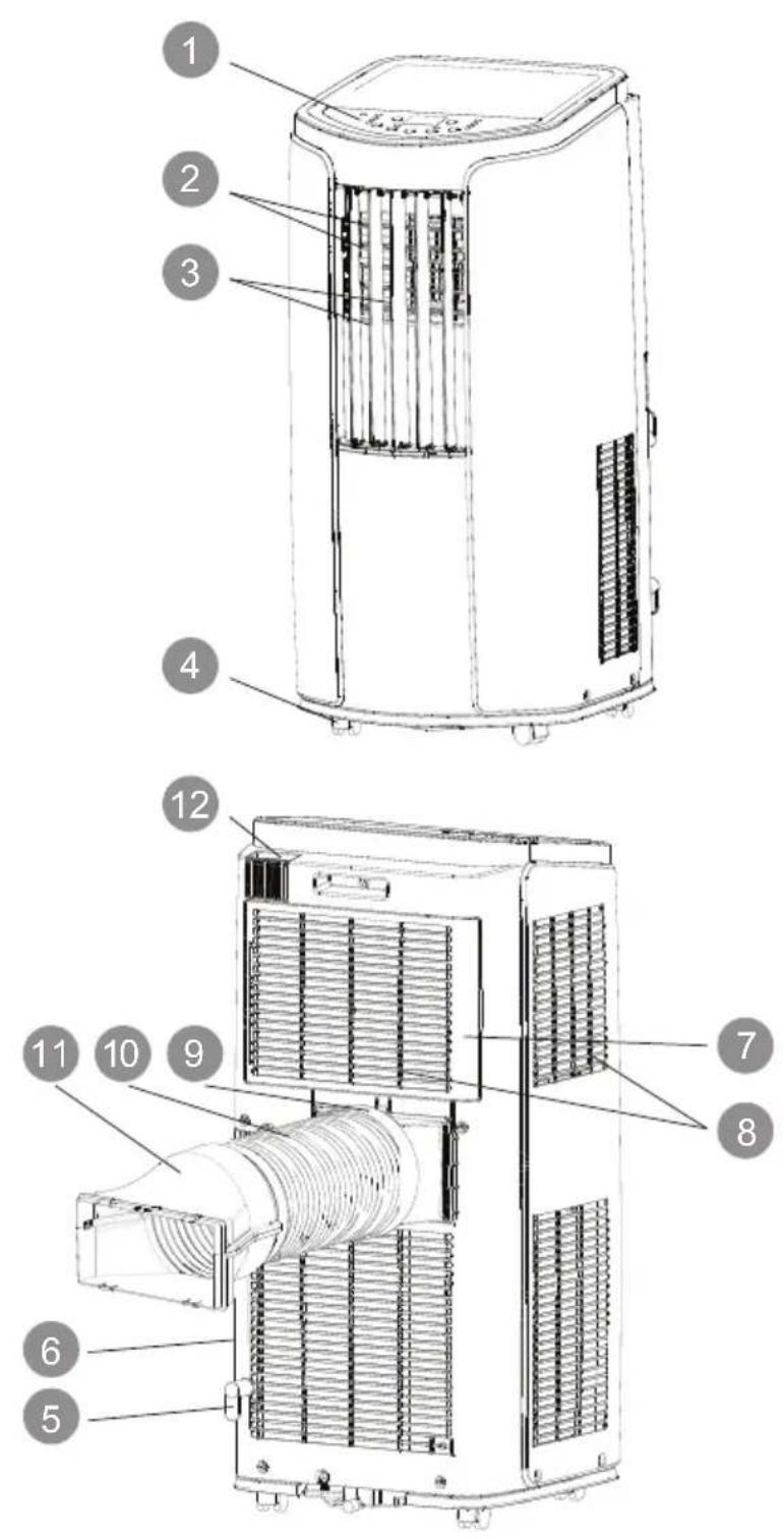
1 Controller panel
2 Guide louver
3 Swing louver
4 Castor
5 Wire-fixing hook
6 Plug of power cord
7 Filter
8 Air inlet
9 Joint A
10 Heat discharge pipe
11 Joint B+C
12 Remote controller hook

Remote controller
NOTICE:
Installation accessories can't be discarded.
Operation Introduction for Control Panel
Name of control panel

Operation of control panel
NOTICE:
- After putting through the power, the air conditioner will give out a sound. After that, you can operate the air conditioner by the control panel.
- Under ON status, after each pressing of the button on control panel, the air conditioner will give out a sound. Meanwhile, corresponding indicator on control panel will be bright.
- Under OFF status, dual-8 nixie tube on control panel won't display. Under ON status, dual-8 nixie tube on control panel will display set temperature under cooling mode and Heating mode (Cool&Heat Unit only), while it won't display under other modes.
1 ON/OFF button
Pressing this button can turn on or turn off the air conditioner.
2 + / - button
Under cooling mode, press “+” or “-” button to increase or decrease set temperature by 1°C. Set temperature range is 16°C\~30°C. Under auto, drying or fan mode, this button is invalid.
Operation Introduction for Control Panel
3 Mode button
Press this button and the mode will circulate according to below sequence:
Cool→Dry→Fan→Heat(Cool&Heat Unit only)
Cool: Under this mode, cooling mode indicator is bright. Dual-8 nixie tube displays set temperature. Temperature setting range is 16°C\~30°C.
Dry: Under this mode, drying mode indicator is bright. Dual-8 nixie tube won't display.
Fan: Under this mode, the air conditioner only blow fan. Fan indicator is bright. Dual-8 nixie tube won't display.
Heat(Cool&Heat Unit only): Under this mode, heating mode indicator is bright.
Dual-8 nixie tube displays set temperature. Temperature setting range is 16^ C\~ 30^ C.
4 Fan button
Press this button and the fan speed will circulate as “low speed→ medium speed → high speed→ auto fan→ low speed”.
5 Timer
Press timer button to enter into timer setting mode. Under this mode, press " + " or " - " button to adjust the timer setting. Timer setting will increase or decrease 0.5 hour by pressing " + " or " - " button within 10 hours, while timer setting will increase or decrease 1 hour by pressing " + " or " - " button beyond 10 hours. After timer setting is finished, the unit will display temperature if there's no operation for 5s. If timer function is started up, the upper indicator will keep the display status. Others, it won't be displayed. Under timer mode, press timer button again to cancel timer mode.
6 Wifi button
After the unit is powered up, press WIFI button to turn on or off WIFI function. Press and hold the button for 10s to reset WIFI function.
To change air flow direction
-
Up/down air flow direction
-
Hold the horizontal louvers as shown in the diagram and adjust the air flow direction.
- Do not adjust the horizontal louvers to the lowest or the highest position in the COOL or DRY mode with the fan speed set to Low for an extended period of time, Condensation may form on the louvers.

natural_image
Illustration of a hand placing a grid panel into an air conditioner unit, with no text or symbols present.- Left/right air flow direction Hold the vertical louver as shown in the diagram and adjust the air flow direction.
CAUTION:
- Do not adjust the vertical louvers to the extreme left or right in the COOL or DRY mode with the fan speed set to Low for an extended period of time. Condensation may form on the louvers.

natural_image
Illustration of a hand operating a refrigerator with a magnified inset showing the interior structure (no text or symbols)Using the remote control
This is a general use remote controller, it could be used for the air conditioners with multifunction; For some function, which the model doesn't have, if press the corresponding button on the remote controller that the unit will keep the original running status.
How to use the remote control
Point the remote control toward the Signal receiver and press the desired button. The unit generates a beep when it receives the signal.
• Make sure nothing, such as curtains, blocks the signal receiver window.
• The signal effective distance is 8m.
CAUTION:
- Do not expose the receiver window to direct sunlight. This may adversely affect its operation.
- Use of certain fluorescent lamp in the same room may interfere with transmission of the signal.
- Do not leave the remote control in direct sunlight or near a heater. Protect the remote control from moisture and shock.
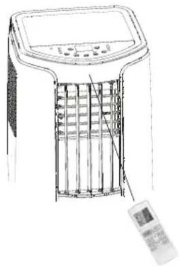
natural_image
Line drawing of a portable air conditioner unit with control panel and display panel (no text or symbols)To prevent the remote control from being misplaced, hook it to the unit when not in use.
When attached, to remove the remote control from the unit, lift the remote control up slightly and pull it out.

Buttons on remote controller
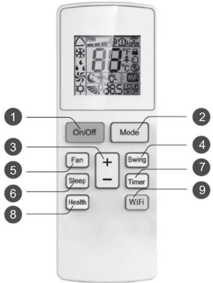
1 On/Off button
2 Mode button
3 + / - button
4 Swing button
(This function is not applicable for this model.)
5 Fan button
6 Sleep button
7 Timer button
8 Health button
(This function is not applicable for this model.)
9 WiFi button
Introduction for icons on display screen

NOTICE: "WiFi" This is a general remote controller. Some models have this function while some do not. Please refer to the actual models.
Introduction for buttons on remote controller
Note:
- This is a general use remote controller, it could be used for the air conditioners with multifunction; For some function, which the model doesn't have, if press the corresponding button on the remote controller that the unit will keep the original running status.
1 ON/OFF button
Press this button to turn on the unit. Press this button again to turn off the unit.
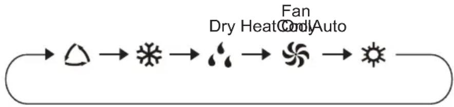
2 MODE button
Press this button can your required operation mode in turn. Corresponding indicator will be on.
flowchart
graph LR
    A["Sun"] --> B["Triangle"]
    B --> C["Syring Circle"]
    C --> D["Spiral Wind Turbine"]
    D --> E["Sun"]
    style A fill:#f9f,stroke:#333
    style E fill:#f9f,stroke:#333
    note right of C Dry Heat Cool Auto
    note right of D Cool Auto
    note right of D Dry Heat Cool Auto
- Auto: Under this mode, the unit will operate automatically according to ex-factory setting. In this case, set temperature cannot be adjusted.
- Cool: Under this mode, air conditioner operates under cooling mode. Cooling indicator will be on. Press “Fan Speed” button can adjust the fan speed.
- Dry: Under this mode, the unit runs in low fan speed for dehumidification and the corresponding indicator is on; under dry mode, the fan speed cannot be adjusted.
- Fan Only: Under this mode, air conditioner will not cool or heat, only blow wind. Fan indicator will be on. Press “Fan Speed” button can adjust the fan speed.
- Heat: Under this mode, air conditioner operates under heating mode. Press “Fan Speed” button can adjust the fan speed.(Cooling only unit won’t receive heating mode signal. If setting heat mode with remote controller, press ON/OFF button can’t start up the unit).
3 + / - button
- Pressing “+” or “-” button once will increase or decrease set temperature by 1°F(°C). Hold “+” or “-” button for 2s, set temperature on remote controller will change quickly.
Release the button after your required set temperature is reached.
- Under timer setting status, after each pressing of “+” or “-” button, time will increase or decrease 0.5h. Hold “+” or “-” button, 2s later, time displayed on dual-8 nixie tube will change quickly. Loosen the button until the time is reached to your set time.
Introduction for buttons on remote controller
4 Swing button (This function is not applicable for this model.)
Press this button to turn "ON" & "OFF" swing.
5 Fan button
This button is used for setting Fan Speed in the sequence that goes from AUTO, ▲, ▲, to ▲ then back to Auto.

flowchart
graph LR
    A["Auto"] --> B["Step 1"]
    B --> C["Step 2"]
    C --> D["Step 3"]
    D --> E["End"]
NOTE: There are 3 speeds for the Fan Speed of this model.
6 Sleep button
Press this button to go into the Sleep operation mode. Press it again to cancel this function. This function is available in COOL, HEAT (Only for models with heating function) mode to maintain the most comfortable temperature for you.
7 Timer button
Under ON status, press this button to set timer OFF; Under OFF status, press this button to set timer ON.
Press this button once and the characters of HOUR ON (OFF) will ✉ash to be displayed. Meanwhile, press “+” button or “-” button to adjust timer setting (time will change quickly if holding “+” or “-” button). Time setting range is 0.5\~24hours.
Press this button again to confirm timer setting and the characters of HOUR ON (OFF)will stop flashing.
If the characters are flashing but you haven't press timer button, timer setting status will be quit after 5s. If timer is confirmer, press this button again to cancel timer.
8 Health button (This function is not applicable for this model.)
Press this button to achieve the on and off of healthy and scavenging functions in operation status. Press this button for the first time to start scavenging function; LCD displays "♠". Press the button for the second time to start healthy and scavenging functions simultaneously; LCD displays "♠" and "♠". Press this button for the third time to quit healthy and scavenging functions simultaneously. Press the button for the fourth time to start healthy function; LCD display "♠". Press this button again to repeat the operation above.
- This function is applicable to partial of models.
Introduction for buttons on remote controller
9 WiFi button
Press "WiFi" button to turn on or turn off WiFi function. When WiFi function is turned on, the "WiFi" icon will be displayed on remote controller; Under status of unit off, press "Mode" and "WiFi" buttons simultaneously for 1s, WiFi module will restore to factory default setting.
This function is only available for some models.
Function introduction for combination buttons
Temperature display switchover function
Under OFF status, press "-" and "Mode" buttons simultaneously to switch temperature display between °C and °F.
Light function
Under switch-on or switch-off state, you may hold "+" and "FAN" buttons simultaneously to set the lamp on or off and send the code. After being energized the lamp is defaulted on.
Replacement of batteries in remote controller
- Press the back side of remote controller marked with "OPEN", as shown in the fig, and then push out the cover of battery box along the arrow direction.
- Replace two 7# (AAA 1.5V) dry batteries, and make sure the position of "+" polar and "-" polar are correct.
Reinstall the cover of battery box.3.

NOTICE
- The distance between signal sender and receiving window should be no more than 8m, and there should be no obstacles between them.
- As the signal will be interfered in the room with electronic fluorescent lamp, conversion fluorescent lamp or wireless phone, please get closer to the air conditioner when using the remote controller.
- Replace new batteries of the same model when replacement is required.
- When you don't use remote controller for a long time, please take out the batteries.
Clean and Maintenance

WARNING:
- Before cleaning the air conditioner, please turn off the unit and disconnect power. Otherwise, it may cause electric shock.
- Do not wash air conditioner with water. Otherwise, it may cause electric shock.
- Do not use volatile liquid (such as thinner or gas) to clean the air conditioner. Otherwise, it may damage the appearance of air conditioner.
Clean outer case and grille
Clean outer case:
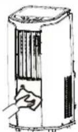
If there's dust on the surface of outer case, please use soft towel to wipe it. If the outer case is very dirty (such as grease), please use neutral abluent to wipe it.
Clean grille: Use cleaner or soft brush to clean it.
natural_image
Simple line drawing of a hand inserting a component into a cylindrical device (no text or symbols)Clean filter
- Remove the filter
a. Press the clasp as shown in the fig, and then remove the filter 1; b. Pull out the filter 2.

- Clean filter
Use cleaner or water to clean the filter. If the filter is very dirty (such as grease), use warm water 40°C melted with neutral abluent to clean it and then put at shady place to dry it.
- Install filter
After the filer is cleaned and dried, reinstall it well.

natural_image
Illustration of a hand pressing down on a grid-patterned surface (no text or symbols)NOTICE:
- The filter should be cleaned about once every three months. If there's much dust in the operation environment, you can increase clean frequency.
- Do not dry the filter with fire or hair drier. Otherwise, it may be deformed or catch fire.
Clean and Maintenance
NOTICE
- The filter should be cleaned about once every three months. If there's much dust in the operation environment, you can increase clean frequency.
- Do not dry the filter with fire or hair drier. Otherwise, it may be deformed or catch fire.
Clean heat discharge pipe
Remove the heat discharge pipe from air conditioner, clean and dry it, and then reinstall it. (For the method of installation and removal, please refer to the instruction for "Installation and disassembly of heat discharge pipe").
Checking before use-season
- Check whether air inlets and air outlets are blocked.
- Check whether plug and socket are in good condition.
- Check whether filter is clean.
- Check whether batteries are installed in remote controller.
- Check whether joint, window bracket and heat discharge pipe are installed tightly.
- Check whether heat discharge pipe is damaged.
Checking after use-season
- Disconnect power supply.
- Clean filter and outer case.
- Remove dust and sundries on the air conditioner.
- Eliminate accumulated water in chassis (refer to the section of "Drainage way" for details).
- Check whether window bracket is damaged or not. If yes, please contact dealer.
Long-time storage
If you don't use the air conditioner for a long time, please maintain it by following steps for good performance:
- Make sure there's no accumulated water in chassis and the heat discharge pipe is disassembled.
- Pull out the plug and wrap the power cord.
- Clean the air conditioner and pack it well to prevent dust.
Notice for recovery
- Many packing materials are recyclable materials. Please deal with them through local recycle bin.
- If you want to throw away the air conditioner, please contact local division or consultant service center for the correct disposal method.
Malfunction analysis
Please check below items before asking for maintenance. If the malfunction still can't be eliminated, please contact local dealer or qualified professionals.
| Phenomenon | Troubleshooting Solution | |
| Air conditioner can't operate | Power failure? | Wait after power recovery. |
| Is plug loose? | Reinsert the plug. | |
| Whether the air switch is tripped off or fuse is burnt? | Ask professional person to replace air switch or fuse. | |
| Is there's malfunction for the circuit? | Ask professional person to replace circuit. | |
| Whether the unit is restarted up after stopping immediately? | Wait for 3min, and then turn on the unit again. | |
| Poor cooling (heating) | Is the power too low? | Wait after voltage is resumed. |
| Whether the air filter is too dirty? | Clean the air filter. | |
| Whether the set temperature is proper? | Adjust the temperature. | |
| Whether door and window are closed? | Close door and window. | |
| Air conditioner can't receive signal from remote controller or remote controller is not sensible. | Whether the unit is interfered seriously (such as static pressure, unstable voltage)? | Please pull out the plug. Insert the plug after about 3min, and then turn on the unit. |
| Whether remote controller is within the receiving range? | The receiving range of remote controller is 8m. Do not exceed this range. | |
| Whether it's blocked by obstacles? | Remove the obstacles. | |
| Is sensitivity of remote controller low? | Check the batteries of remote controller. If the power is low, please replace the batteries. | |
| Whether there's fluorescence lamp in the room? | Move the remote controller close to air conditioner.Turn off the fluorescence lamp and try it again. |
Malfunction analysis
| Phenomenon Troubleshooting Solution | ||
| No air blowed out from air conditioner | Whether air outlet or air inlet is blocked? | Eliminate the obstacles. |
| Under heating mode, whether indoor temperature ireaches set temperature? | The unit will stop blowing fan after reaching set temperature. | |
| Whether heating mode is started up just now? | In order to prevent cold air, air conditioner will delay for a while to be started up, which is the normal phenomenon. | |
| Whether evaporator is defrosted? (observe it by pulling out the filter) | It's the normal phenomenon. Air conditioner is defrosting. After defrosting is finished, it will resume operation. | |
| Set temperature can't be adjusted. | Whether the unit operates under auto mode? | Temperature can't be adjusted under auto mode. |
| Whether the required temperature exceeds the temperature setting range? | Temperature setting range: 16°C-30°C . | |
| There's off flavour | There's off-flavour source in the room, such as furniture, cigarette etc. | Eliminate the off-flavour source.Clean the filter. |
| There's abnormal sound during operation | Whether the unit is interfered by thunder, radio, etc? | Disconnect power, put through the power again, and then turn on the unit again. |
| You can heard water-flowing sound | Whether the unit is turned on or turned off just now? | There's flowing sound of refrigerant inside the air conditioner, which is the normal phenomenon. |
| You can heard the sound of "PAPA" | Whether the unit is turned on or turned off just now? | Heat expansion or shrinkage for the panel due to change of temperature, which cause friction sound. |
Malfunction analysis
Malfunction code
| ERROR CODE | Troubleshooting |
| F0 | Please contact qualified professionals for service. |
| F1 | Please contact qualified professionals for service. |
| F2 | Please contact qualified professionals for service. |
| F4 | Please contact qualified professionals for service. |
| E8 | 1. Check if the unit is under high-temperature and high-humidity environment; if ambient temperature is too high, power off the unit and then energize it for operation after the ambient temperature drops to 35°C below.2. Check if the evaporator and condenser are blocked by some objects; if yes, take away the objects, power off the unit and then energize it for operation.3. If the malfunction still occur, please contact our after-sales service center. |
| H3 | |
| H8 | 1. Pour out the water inside chassis.2. If "H8" still exits, please contact professional person to maintain the unit. |

WARNING
- If there're following phenomenon, please turn off the air conditioner and disconnect the power immediately, and then contact dealer immediately.
→ Power cord is overheating or damaged.
→ Abnormal sound during operation.
→ Off-flavor.
→ Water leakage
- Do not repair or refit the air conditioner by yourself.
- If operate the air conditioner under abnormal condition, it may cause malfunction, electric shock or fire hazard.

WARNING:
- Observe all governing codes and ordinances.
- Do not use damaged or non-standard power cord.
- Be caution during installation and maintenance. Prohibit incorrect operation to prevent electric shock, casualty and other accidents.
Selection of installation location
Basic requirement
Installing the unit in the following places may cause malfunction. If it is unavoidable, please consult the local dealer:
- The place with strong heat sources, vapors, flammable or explosive gas, or volatile objects spread in the air.
- The place with high-frequency devices (such as welding machine, medical equipment).
- The place near coast area.
- The place with oil or fumes in the air.
- The place with sulfureted gas.
- Other places with special circumstances.
- It's not allowed to be installed on the unstable or motive base structure (such as truck) or in the corrosive environment (such as chemical factory).
Requirement of air conditioner
- Air inlet should be far away from obstacles and do not put any objects near air outlet. Otherwise, it will affect the radiation of heat discharge pipe.
- Select a location where the noise and outflow air emitted by the outdoor unit will not affect neighborhood.
- Please try your best to keep far away from fluorescent lamp.
- The appliance shall not be installed in the laundry.
Requirements for electric connection
Safety precaution
- Must follow the electric safety regulations when installing the unit.
- According to the local safety regulations, use qualified power supply circuit.
- For appliances with type Y attachment, the instructions shall contain the substance of the following. If the supply cord is damaged, it must be replaced by the manufacturer, its service agent or similarly qualified persons in order to avoid a hazard.
- Properly connect the live wire, neutral wire and grounding wire of power socket.
- Be sure to cut off the power supply before proceeding any work related to electricity and safety.
-
Do not put through the power before finishing installation.
-
The air conditioner is first class electric appliance. It must be properly grounding with specialized grounding device by a professional. Please make sure it is always grounded effectively, otherwise it may cause electric shock.
-
The yellow-green wire or green wire in air conditioner is grounding wire, which can't be used for other purposes.
-
The grounding resistance should comply with national electric safety regulations.
-
The appliance shall be installed in accordance with national wiring regulations.
-
To be in compliance with IEC 61000-3-11, impedance value of power-supply system connected to product must be less than or equal to the allowable maximum value of |Zsys| in the following sheet:
| models | max |Zsys| unit:ohms |
| GPC12AL-K5NNA3CGPH12AL-K5NNA3C | 0.12 |
Preparation before Installation
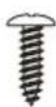
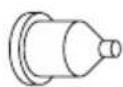
NOTICE: Check if the accessories are available before installation.
Accessory list
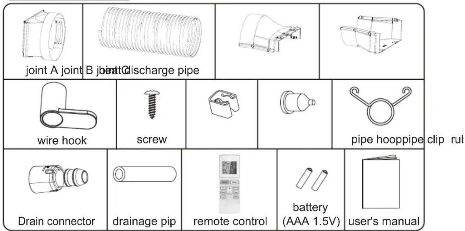
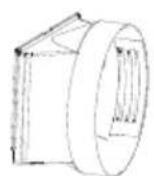

natural_image
Line drawing of a coiled spring or tube with no text or symbols





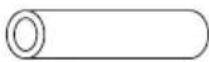

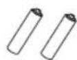
Optional

Tools needed for installation
| cross screwdriver | straight screwdriver | saw |
| gauge | scissors | pencil |
Install Wire Hook
- Assemble the wire hook at the back of the unit with screws (the direction of wire hook is as shown in following fig).
direction of wire hook is upward

- Wind the power cord around the wire hook.

natural_image
Technical line drawing of a multi-level air conditioning unit with ventilation grilles and control panel (no text or labels)Removing Collected Water
There are 2 ways to remove collected water:
1 Use the continuous drainage option from the lower hole.
NOTICE: When using the continuous drainage option from the bottom hole, install drainage pipe as follow before using, otherwise poor drainage will affect normal operation of the unit.
■ Instructions for drainage pipe installation.
- Fix the drainage pipe clip on the right of rear side plate near drainage port with a screw.

- Remove the rubber plug at drainage port.

-
Put the drainage pipe into drainage port and screw it up, and then bind it with pipe hoop.
-
Put the rubber plug into the other side of drainage pipe, fix it with pipe hoop and then fix it in the drainage pipe clip.
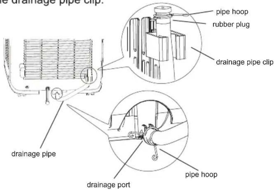
Removing Collected Water
■ Drainage way as follows.
- In Cool, Dry or Heat mode operating, the condensation water will be drained to the chassis.
-
When the chassis is full with water, the buzzer will give out 8 sounds and "H8" is displayed to remind user to discharge water:
-
Move the unit to a suitable place for discharging water; do not tilt the unit and keep it horizontal during moving;
- Take the drainage pipe from the clip and pull out the rubber plug on the drainage pipe to discharge water;
- Put back the rubber plug onto drainage pipe after finishing discharging water and then fix the pipe on the clip;
- After full water protection is eliminated and the compressor has been stopped for 3 minutes, the unit will resume operation.

natural_image
Technical line drawing of a multi-tiered industrial air conditioning unit with ventilation grilles and cooling fans (no text or labels)Removing Collected Water
2 Use the continuous drainage option from the middle hole.
NOTICE: Water can be automatically emptied into a floor drain by attaching 14mm inner diameter hose (not included).
- Remove the continuous drain cap 1 by turning it counter clockwise then remove the rubber stopper 2 from the spout.

-
Screw the drain connector to(included in the package) the spout by turning clockwise.
-
Insert the drainage hose into drain connector.

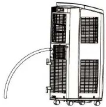
natural_image
Technical line drawing of a multi-level industrial control unit with visible heat sinks and cooling pipes (no text or labels)ATTENTION:
When using continuous drainage option from the middle hole, place portable on a level surface and make sure garden hose is clear of any obstructions and is directed downward. Placing portable on an uneven surface or improper hose installation may result in water filling up the chassis and causing the unit to shut off. Empty water in the chassis if shut off occurs, then check portable location and hose for proper setup.

Installation in a double-hung sash window(Optional)
- Connect the rain guards to the insect guard net.
Insert all three projections on each rain guard into the holes in the insect guard net.
Side "A" will now be at the top, as indicated in the diagram.

- Attach the guard combined above to the window panel.
Push the insect guard net firmly to ensure that its four projections fit into the holes in the window panel.
Side “A” will now be at the top, as indicated in the diagram.

- Cut the sponge A (adhesive type) to the proper length and attach it to the window stool and to the bottom of sash.
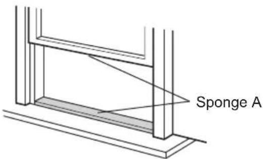
- Attach the window panel to the window stool.
Make sure that the exhaust cover is attached to the window panel.
Inner width of the window:20.5"(520mm)
Use the window panel.
Installation in a double-hung sash window(Optional)
The window panel cannot be installed in windows less than 20.5" (520mm) wide, as you will be unable to shut the exhaust cover.
(1) Open the window sash and place the window panel on the window sill.
(2) Secure the window panel to the window stool with screws.


natural_image
Architectural elevation drawing of a building facade with horizontal and vertical measurements (no text or symbols)Inner width of the window:20.5" (520mm)- 38.5" (980mm)
Use the window panel and the adjustment panel.
(1) Open the window sash and place the window panel on the window sill.
(2) Slide the adjustment panel to fit the window frame width.
(3) Secure the window panel to the sill with screws.

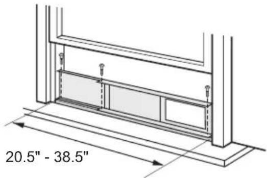
Inner width of the window:38.5" (980mm) - 59" (1500mm)
Use the window panel, the adjustment panel and the extension panel.
(1) Open the window sash and place the window panel on the window sill.
(2) Slide the adjustment and extension panels to fit the window frame width.
(3) Secure the window panel to the window sill with screws.

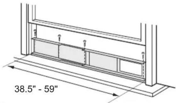
Installation in a double-hung sash window(Optional)
- Close the window sash securely against the Window panel.

natural_image
Technical line drawing of a structural beam with supports and a central panel (no text or symbols)- Stuff the sponge B between the glass and the window to prevent air and insects from getting into the room.
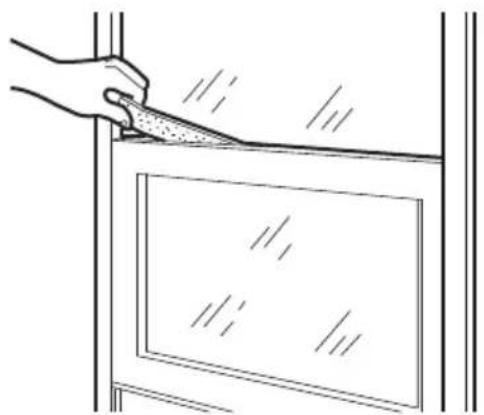
natural_image
Line drawing of a hand using a tool to cut or mark a rectangular object, with no visible text or symbols.- Attach the bracket with a screw.(Recommended)
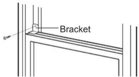
Please lay a tabular material underneath the window panel in case you could not attach the rain guard or the window adapter properly due to the deep window sill.
Installation in a sliding sash window(Optional)
- Connect the rain guards to the insect guard net.
Insert all three projections on each rain guard into the holes in the insect guard net. Side “A” will now be at the top, as indicated in the diagram.
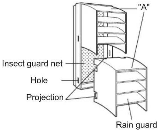
- Attach the guard combined above to the window panel.
Push the insect guard net firmly to ensure that its four projections fit into the holes in the window panel.
Side “A” will now be at the top, as indicated in the diagram, when it is installed in the window.

- Cut the sponge A (adhesive type) to the proper length and attach it to the window frame and to the side of sash.

- Install the window panel into the window frame.
Make sure that the exhaust cover is attached to the window panel.
Inner height of the window:20.5"(520mm)
Use the window panel.
Installation in a sliding sash window(Optional)
The window panel cannot be installed in windows less than 20.5" (520mm) high, as you will be unable to shut the exhaust cover.
(1) Open the window sash and place the window panel on the window frame.
(2) Secure the window panel to the window frame with screws.
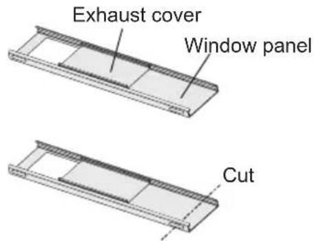

Inner height of the window:20.5" (520mm)- 38.5" (980mm)
Use the window panel and the adjustment panel.
(1) Open the window sash and place the window panel on the window frame.
(2) Slide the adjustment panel to fit the window frame height.
(3) Secure the window panel to the window frame with screws.


Inner height of the window:38.5" (980mm) - 59" (1500mm)
Use the window panel, the adjustment panel and the extension panel.
(1) Open the window sash and place the window panel on the window frame.
(2) Slide the adjustment and extension panels to fit the window frame height.
(3) Secure the window panel to the window frame with screws.


Installation in a sliding sash window(Optional)
- Close the window sash securely against the Window panel.

natural_image
Technical line drawing of a door frame with a side panel (no text or symbols)- Stuff the foam seal B between the glass and the window to prevent air and insects from getting into the room.

natural_image
Line drawing of a hand using a tool to cut or mark a window frame (no text or symbols)- Attach the bracket with a screw.(Recommended)
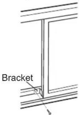
Please lay a tabular material underneath the window panel in case you could not attach the rain guard or the window adapter properly due to the deep window sill.
Installation and Disassembly of Heat Discharge Pipe
Install heat discharge pipe
- Rotate joint A and joint B clockwise into the two ends of heat discharge pipe.

- Insert joint A of heat discharge pipe (the side with "TOP" is upwards) into the groove until you hear a sound.

-
Lead the exhaust hose outdoors.
-
Slide and open the exhaust cover on the window panel, and attach the window adapter. (Optional)

natural_image
Illustration of a hand holding a component inside a structural frame (no text or symbols)
natural_image
Technical illustration showing two views of a pipe installation: top view with coiled duct and wall, bottom view with hand holding panel (no text or symbols)Installation and Disassembly of Heat Discharge Pipe
Note of Installingheat discharge pipe
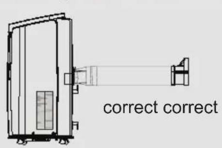
In order to improve cooling efficiency, the heat discharge pipe should be as short as possible and flat without curve to ensure smooth heat discharge.

natural_image
Technical line drawing of a mechanical or electrical component with no visible text or symbols

- The length of the heat discharge pipe is less than 1m. It is recommended to use it with shortest length.
- When installing, heat discharge pipe should be as flat as possible. Don't prolong the pipe or connect it with other heat discharge pipe.

natural_image
Technical line drawing of a large industrial air conditioning unit with coiled ducts and control panel (no text or symbols)Installation and Disassembly of Heat Discharge Pipe
- Correct installation is as shown in figure (When installing it on wall, height of hall should not be over 130cm from floor).
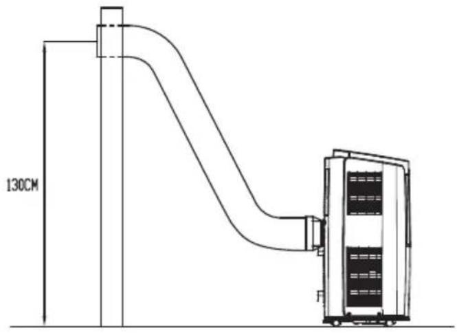
- Wrong installation is shown in following figure (If the pipe is bent too much, it would easily cause malfunction.)

natural_image
Diagram showing a curved duct with a cross mark and a vertical container, no text or symbols presentDisassemble heat discharge pipe
- Remove joint B+C from1. Remove j
Press the clasp and lift joint A upwards to outdoors. remove it.


Installation and Disassembly of Heat Discharge Pipe
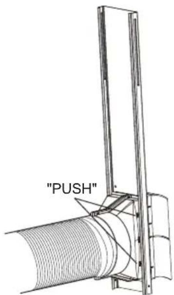
- Remove the window adapter. Pull out and remove the window adapter by pushing down two "PUSH" markings, and slide and close the exhaust cover in the window panel. (Optional)

Operation Test
- Put through the power supply and then press ON/OFF button on remote controller to start the unit.
- Press mode button to select auto, cooling, drying, fan or heating function, and then check if the unit operates normally.
- If ambient temperature is below 16^ , the unit can't operate in cooling mode.
Electric Schematic Diagram
The Electric schematic diagram are subject to change without notice. Please refer to which one on the unit.
GPC12AL-K5NNA3C:
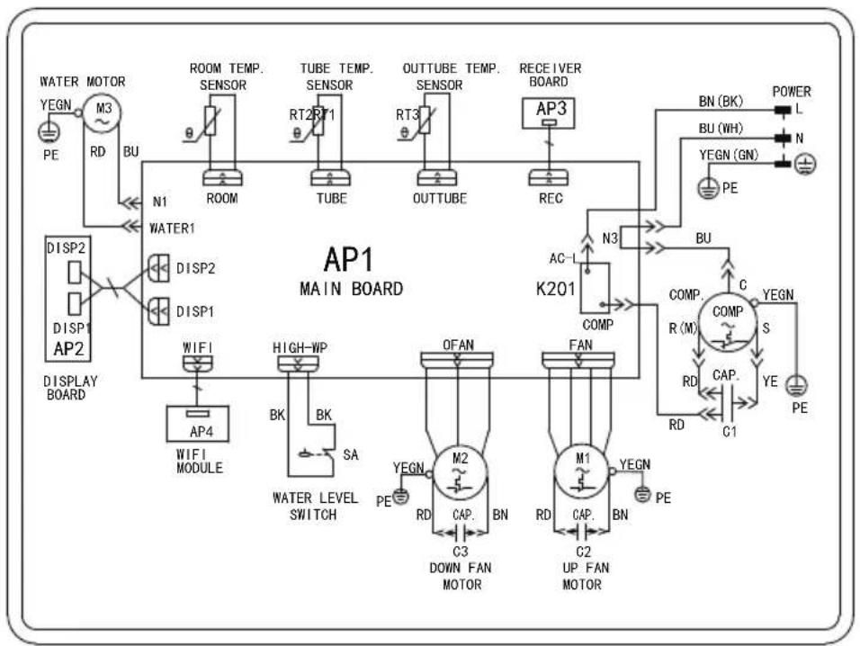
flowchart
graph TD
    subgraph AP1_MAIN_BOARD
        A["WATER MOTOR M3 PE"] --> B["RD BU"]
        B --> C["N1 WATER1"]
        C --> D["DISP2"]
        D --> E["DISP1"]
        E --> F["DISPLAY BOARD"]
        G["ROOM TEMP. SENSOR"] --> H["ROOM"]
        I["TUBE TEMP. SENSOR"] --> J["TUBE"]
        K["OUTTUBE TEMP. SENSOR"] --> L["OUTTUBE"]
        M["RECEIVER BOARD AP3"] --> N["REC"]
        O["POWER"] --> P["L"]
        Q["BU (WH)"] --> R["N"]
        S["YEGN (GN)"] --> T["PE"]
        U["AC-L K201"] --> V["N3"]
        W["BU"] --> X["COMP R(M)"]
        Y["COMP S RD CAP.C1"] --> Z["YEGN YE PE"]
    end
    subgraph AP1_MAIN_BOARD
        AA["WIFI"] --> AB["AP4"]
        AC["HIGH-WP BK SA"] --> AD["WATER LEVEL SWITCH"]
        AE["OFAN"] --> AF["M2"]
        AG["FAN"] --> AH["M1"]
        AI["UP FAN MOTOR"] --> AJ["C2"]
        AK["DOWN FAN MOTOR"] --> AL["C3"]
        AM["YEGN PE"] --> AN["RD CAP. BN"]
        AO["YEGN PE"] --> AP["UP FAN MOTOR"]
    end
    AP1_MAIN_BOARD --> AP1_MAIN_BOARD
    AP1_MAIN_BOARD --> AP1_MAIN_BOARD
    style AP1_MAIN_BOARD fill:#f9f,stroke:#333
GPH12AL-K5NNA3C:

flowchart
graph TD
    A["AP1 MAIN BOARD"] --> B["AP2"]
    B --> C["DISP1"]
    B --> D["DISP2"]
    B --> E["DISP3"]
    B --> F["DISP4"]
    B --> G["DISP5"]
    B --> H["DISP6"]
    B --> I["DISP7"]
    B --> J["DISP8"]
    B --> K["DISP9"]
    B --> L["DISP10"]
    B --> M["DISP11"]
    B --> N["DISP12"]
    B --> O["DISP13"]
    B --> P["DISP14"]
    B --> Q["DISP15"]
    B --> R["DISP16"]
    B --> S["DISP17"]
    B --> T["DISP18"]
    B --> U["DISP19"]
    B --> V["DISP20"]
    B --> W["DISP21"]
    B --> X["DISP22"]
    B --> Y["DISP23"]
    B --> Z["DISP24"]
    B --> AA["DISP25"]
    B --> AB["DISP26"]
    B --> AC["DISP27"]
    B --> AD["DISP28"]
    B --> AE["DISP29"]
    B --> AF["DISP30"]
    B --> AG["DISP31"]
    B --> AH["DISP32"]
    B --> AI["DISP33"]
    B --> AJ["DISP34"]
    B --> AK["DISP35"]
    B --> AL["DISP36"]
    B --> AM["DISP37"]
    B --> AN["DISP38"]
    B --> AO["DISP39"]
    B --> AP["DISP40"]
    B --> AQ["DISP41"]
    B --> AR["DISP42"]
    B --> AS["DISP43"]
    B --> AT["DISP44"]
    B --> AU["DISP45"]
    B --> AV["DISP46"]
    B --> AW["DISP47"]
    B --> AX["DISP48"]
    B --> AY["DISP49"]
    B --> AZ["DISP50"]
    B --> BA["DISP51"]
    B --> BB["DISP52"]
    B --> BC["DISP53"]
    B --> BD["DISP54"]
    B --> BE["DISP55"]
    B --> BF["DISP56"]
    B --> BG["DISP57"]
    B --> BH["DISP58"]
    B --> BI["DISP59"]
    B --> BJ["DISP60"]
    B --> BK["DISP61"]
    B --> BL["DISP62"]
    B --> BM["DISP63"]
    B --> BN["DISP64"]
    B --> BO["DISP65"]
    B --> BP["DISP66"]
    B --> BQ["DISP67"]
    B --> BR["DISP68"]
    B --> BS["DISP69"]
    B --> BT["DISP70"]
    B --> BU["DISP71"]
    B --> BV["DISP72"]
    B --> BW["DISP73"]
    B --> BX["DISP74"]
    B --> BY["DISP75"]
    B --> BZ["DISP76"]
    B --> CA["DISP77"]
    B --> CB["DISP78"]
    B --> CC["DISP79"]
    B --> CD["DISP80"]
    B --> CE["DISP81"]
    B --> CF["DISP82"]
    B --> CG["DISP83"]
    B --> CH["DISP84"]
    B --> CI["DISP85"]
    B --> CJ["DISP86"]
    B --> CK["DISP87"]
    B --> CL["DISP88"]
    B --> CM["DISP89"]
    B --> CN["DISP90"]
    B --> CO["DISP91"]
    B --> CP["DISP92"]
    B --> CQ["DISP93"]
    B --> CR["DISP94"]
    B --> CS["DISP95"]
    B --> CT["DISP96"]
    B --> CU["DISP97"]
    B --> CV["DISP98"]
    B --> CW["DISP99"]
    B --> CX["DISP100"]
Specialist's Manual
Aptitude requirement for maintenance man(repairs should be done only be specialists).
a. All the work men who are engaging in the refrigeration system should bear the valid certification awarded by the authoritative organization and the qualification for dealing with the refrigeration system recognized by this industry.
b. It can only be repaired by the method suggested by the equipment's manufacturer. If it needs other technician to maintain and repair the appliance, they should be supervised by the person who bears the qualification for using the flammable refrigerant. Safety preparation work before installation
The safety must be inspected before maintaining the appliances with the flammable refrigerant for reducing the flammable hazard to the lowest.
Work shall be undertaken under a controlled procedure so as to minimise the risk of a flammable gas or vapour being present while the work is being performed. Detection of flammable refrigerants
Under no circumstances shall potential sources of ignition be used in the searching for or detection of refrigerant leaks. A halide torch (or any other detector using a naked flame) shall not be used.
Environment checking
- All maintenance staff and others working in the local area shall be instructed on the nature of work being carried out. Work in confined spaces shall be avoided. The area around the workspace shall be sectioned off. Ensure that the conditions within the area have been made safe by control of flammable material.
- The area shall be checked with an appropriate refrigerant detector prior to and during work, to ensure the technician is aware of potentially toxic or flammable atmospheres. Ensure that the leak detection equipment being used is suitable for use with all applicable refrigerants, i.e. non-sparking, adequately sealed or intrinsically safe.
- No person carrying out work in relation to a refrigeration system which involves exposing any pipe work shall use any sources of ignition in such a manner that it may lead to the risk of fire or explosion. All possible ignition sources, including cigarette smoking, should be kept sufficiently far away from the site of installation, repairing, removing and disposal, during which refrigerant can possibly be released to the surrounding space. Prior to work taking place, the area around the equipment is to be surveyed to make sure that there are no flammable hazards or ignition risks. “No Smoking” signs shall be displayed.
- If any hot work is to be conducted on the refrigeration equipment or any associated parts, appropriate fire extinguishing equipment shall be available to hand. Have a dry powder or CO_2 fire extinguisher adjacent to the charging area.
- Ensure that the area is in the open or that it is adequately ventilated before breaking into the system or conducting any hot work. A degree of ventilation shall continue during the period that the work is carried out. The ventilation should safely disperse any released refrigerant and preferably expel it externally into the atmosphere.
Specialist's Manual
Refrigeration equipment Checking
Where electrical components are being changed, they shall be fit for the purpose and to the correct specification. At all times the manufacturer's maintenance and service guidelines shall be followed. If in doubt, consult the manufacturer's technical department for assistance.
The following checks shall be applied to installations using flammable refrigerants:
- The actual refrigerant charge is in accordance with the room size within which the refrigerant containing parts are installed;
- The ventilation machinery and outlets are operating adequately and are not obstructed;
- If an indirect refrigerating circuit is being used, the secondary circuit shall be checked for the presence of refrigerant;
- Marking to the equipment continues to be visible and legible. Markings and signs that are illegible shall be corrected;
- Refrigeration pipe or components are installed in a position where they are unlikely to be exposed to any substance which may corrode refrigerant containing components, unless the components are constructed of materials which are inherently resistant to being corroded or are suitably protected against being so corroded.
Electrical devices checking
Repair and maintenance to electrical components shall include initial safety checks and component inspection procedures. If a fault exists that could compromise safety, then no electrical supply shall be connected to the circuit until it is satisfactorily dealt with. If the fault cannot be corrected immediately but it is necessary to continue operation, an adequate temporary solution shall be used. This shall be reported to the owner of the equipment so all parties are advised.
Initial safety checks shall include:
- That capacitors are discharged: this shall be done in a safe manner to avoid possibility of sparking;
- That no live electrical components and wiring are exposed while charging, recovering or purging the system;
• That there is continuity of earth bonding.
Repairs to sealed components
During repairs to sealed components, all electrical supplies shall be disconnected from the equipment being worked upon prior to any removal of sealed covers, etc. If it is absolutely necessary to have an electrical supply to equipment during servicing, then a permanently operating form of leak detection shall be located at the most critical point to warn of a potentially hazardous situation.
Particular attention shall be paid to the following to ensure that by working on electrical components, the casing is not altered in such a way that the level of protection is affected. This shall include damage to cables, excessive number of connections, terminals not made to original specification, damage to seals, incorrect fitting of glands, etc.
Specialist's Manual
- Ensure that the apparatus is mounted securely.
- Ensure that seals or sealing materials have not degraded to the point that they no longer serve the purpose of preventing the ingress of flammable atmospheres.
Replacement parts shall be in accordance with the manufacturer's specifications.
NOTE : The use of silicon sealant can inhibit the effectiveness of some types of leak detection equipment. Intrinsically safe components do not have to be isolated prior to working on them.
Cabling
Check that cabling will not be subject to wear, corrosion, excessive pressure, vibration, sharp edges or any other adverse environmental effects. The check shall also take into account the effects of aging or continual vibration from sources such as compressors or fans.
Leak detection methods
The following leak detection methods are deemed acceptable for all refrigerant systems.
Electronic leak detectors may be used to detect refrigerant leaks but, in the case of flammable refrigerants, the sensitivity may not be adequate, or may need re-calibration. (Detection equipment shall be calibrated in a refrigerant-free area.) Ensure that the detector is not a potential source of ignition and is suitable for the refrigerant used. Leak detection equipment shall be set at a percentage of the LFL of the refrigerant and shall be calibrated to the refrigerant employed, and the appropriate percentage of gas (25 % maximum) is confirmed.
Leak detection fluids are suitable for use with most refrigerants but the use of detergents containing chlorine shall be avoided as the chlorine may react with the refrigerant and corrode the copper pipe-work.
If a leak is suspected, all naked flames shall be removed/extinguished.
If a leakage of refrigerant is found which requires brazing, all of the refrigerant shall be recovered from the system, or isolated (by means of shut off valves) in a part of the system remote from the leak. For appliances containing flammable refrigerants, oxygen free nitrogen (OFN) shall then be purged through the system both before and during the brazing process
Removal and evacuation
When breaking into the refrigerant circuit to make repairs – or for any other purpose – conventional procedures shall be used. However, for flammable refrigerants it is important that best practice is followed since flammability is a consideration. The following procedure shall be adhered to:
- remove refrigerant;
• purge the circuit with inert gas; - evacuate;
• purge again with inert gas; - open the circuit by cutting or brazing.
Specialist's Manual
The refrigerant charge shall be recovered into the correct recovery cylinders. For appliances containing flammable refrigerants, the system shall be “flushed” with OFN to render the unit safe. This process may need to be repeated several times. Compressed air or oxygen shall not be used for purging refrigerant systems.
For appliances containing flammable refrigerants, flushing shall be achieved by breaking the vacuum in the system with OFN and continuing to fill until the working pressure is achieved, then venting to atmosphere, and finally pulling down to a vacuum. This process shall be repeated until no refrigerant is within the system.
When the final OFN charge is used, the system shall be vented down to atmospheric pressure to enable work to take place. This operation is absolutely vital if brazing operations on the pipe-work are to take place.
Ensure that the outlet for the vacuum pump is not close to any ignition sources and that ventilation is available.
Charging procedures
In addition to conventional charging procedures, the following requirements shall be followed.
- Ensure that contamination of different refrigerants does not occur when using charging equipment. Hoses or lines shall be as short as possible to minimise the amount of refrigerant contained in them.
– Cylinders shall be kept upright.
- Ensure that the refrigeration system is earthed prior to charging the system with refrigerant.
- Label the system when charging is complete (if not already).
– Extreme care shall be taken not to overfill the refrigeration system.
Prior to recharging the system, it shall be pressure-tested with the appropriate purging gas. The system shall be leak-tested on completion of charging but prior to commissioning.
A follow up leak test shall be carried out prior to leaving the site.
Decommissioning
Before carrying out this procedure, it is essential that the technician is completely familiar with the equipment and all its detail. It is recommended good practice that all refrigerants are recovered safely. Prior to the task being carried out, an oil and refrigerant sample shall be taken in case analysis is required prior to re-use of reclaimed refrigerant. It is essential that electrical power is available before the task is commenced.
a) Become familiar with the equipment and its operation.
b) Isolate system electrically.
c) Before attempting the procedure, ensure that:
- mechanical handling equipment is available, if required, for handling refrigerant cylinders;
- all personal protective equipment is available and being used correctly;
- the recovery process is supervised at all times by a competent person;
- recovery equipment and cylinders conform to the appropriate standards.
d) Pump down refrigerant system, if possible.
e) If a vacuum is not possible, make a manifold so that refrigerant can be removed from various parts of the system.
Specialist's Manual
f) Make sure that cylinder is situated on the scales before recovery takes place.
g) Start the recovery machine and operate in accordance with manufacturer's instructions.
h) Do not overfill cylinders. (No more than 80 % volume liquid charge).
i) Do not exceed the maximum working pressure of the cylinder, even temporarily.
j) When the cylinders have been filled correctly and the process completed, make sure that the cylinders and the equipment are removed from site promptly and all isolation valves on the equipment are closed off.
k) Recovered refrigerant shall not be charged into another refrigeration system unless it has been cleaned and checked.
Labelling
Equipment shall be labelled stating that it has been de-commissioned and emptied of refrigerant. The label shall be dated and signed. For appliances containing flammable refrigerants, ensure that there are labels on the equipment stating the equipment contains flammable refrigerant.
Recovery
When removing refrigerant from a system, either for servicing or decommissioning, it is recommended good practice that all refrigerants are removed safely.
When transferring refrigerant into cylinders, ensure that only appropriate refrigerant recovery cylinders are employed. Ensure that the correct number of cylinders for holding the total system charge are available. All cylinders to be used are designated for the recovered refrigerant and labelled for that refrigerant (i.e. special cylinders for the recovery of refrigerant). Cylinders shall be complete with pressure-relief valve and associated shut-off valves in good working order. Empty recovery cylinders are evacuated and, if possible, cooled before recovery occurs.
The recovery equipment shall be in good working order with a set of instructions concerning the equipment that is at hand and shall be suitable for the recovery of all appropriate refrigerants including, when applicable, flammable refrigerants. In addition, a set of calibrated weighing scales shall be available and in good working order. Hoses shall be complete with leak-free disconnect couplings and in good condition. Before using the recovery machine, check that it is in satisfactory working order, has been properly maintained and that any associated electrical components are sealed to prevent ignition in the event of a refrigerant release. Consult manufacturer if in doubt.
The recovered refrigerant shall be returned to the refrigerant supplier in the correct recovery cylinder, and the relevant waste transfer note arranged. Do not mix refrigerants in recovery units and especially not in cylinders.
If compressors or compressor oils are to be removed, ensure that they have been evacuated to an acceptable level to make certain that flammable refrigerant does not remain within the lubricant. The evacuation process shall be carried out prior to returning the compressor to the suppliers. Only electric heating to the compressor body shall be employed to accelerate this process. When oil is drained from a system, it shall be
carried out safely.
deitsu
EUROFRED
being efficient
Eurofred S.A.

- Content
- Operation Notices
- Operation Guide
- Maintenance
- Malfunction
- Installation Notice
- Installation
- Attached Sheet
- Explanation of Symbols
- DANGER
- WARNING
- CAUTION
- Exception Clauses
- The Refrigerant
- WARNING:
- Safety Warning
- Note:
- NOTICE:
- Operation Introduction for Control Panel
- Name of control panel
- Operation of control panel
- ON/OFF button
- + / - button
- Mode button
- Fan button
- Timer
- Wifi button
- To change air flow direction
- CAUTION:
- Using the remote control
- How to use the remote control
- Buttons on remote controller
- Introduction for icons on display screen
- Introduction for buttons on remote controller
- MODE button
- + / - button
- Swing button (This function is not applicable for this model.)
- Fan button
- Sleep button
- Timer button
- Health button (This function is not applicable for this model.)
- WiFi button
- Function introduction for combination buttons
- Temperature display switchover function
- Light function
- Replacement of batteries in remote controller
- NOTICE
- Clean and Maintenance
- Clean outer case and grille
- Clean outer case:
- Clean filter
- Clean heat discharge pipe
- Checking before use-season
- Checking after use-season
- Long-time storage
- Notice for recovery
- Malfunction analysis
- Selection of installation location
- Basic requirement
- Requirement of air conditioner
- Requirements for electric connection
- Safety precaution
- Preparation before Installation
- Install Wire Hook
- Removing Collected Water
- ATTENTION:
- Installation in a double-hung sash window(Optional)
- Installation in a sliding sash window(Optional)
- Installation and Disassembly of Heat Discharge Pipe
- Install heat discharge pipe
- Note of Installingheat discharge pipe
- Disassemble heat discharge pipe
- Operation Test
- Electric Schematic Diagram
- Specialist's Manual
- Refrigeration equipment Checking
- Electrical devices checking
- Repairs to sealed components
- Cabling
- Leak detection methods
- Removal and evacuation
- Charging procedures
- Decommissioning
- Labelling
- Recovery
- deitsu
Brand : DAITSU
Model : ADP-12F/CX-A3
Category : Air conditioner