DUF 18K - Air-conditioner DAITSU - Free user manual and instructions
Find the device manual for free DUF 18K DAITSU in PDF.

User questions about DUF 18K DAITSU
0 question about this device. Answer the ones you know or ask your own.
Ask a new question about this device
Download the instructions for your Air-conditioner in PDF format for free! Find your manual DUF 18K - DAITSU and take your electronic device back in hand. On this page are published all the documents necessary for the use of your device. DUF 18K by DAITSU.
USER MANUAL DUF 18K DAITSU
natural_image
Exterior view of a delfisu air conditioner unit (no text or symbols visible on the device itself)Serie
LIBERTY CASSETTE 3D
Edition
R00
Models
DUF-12K-CF
DUF-18K-CF
DUF-24K-CF
Contents
1 Safety Precautions ....1
2 Outline of the Unit and Main Parts....3
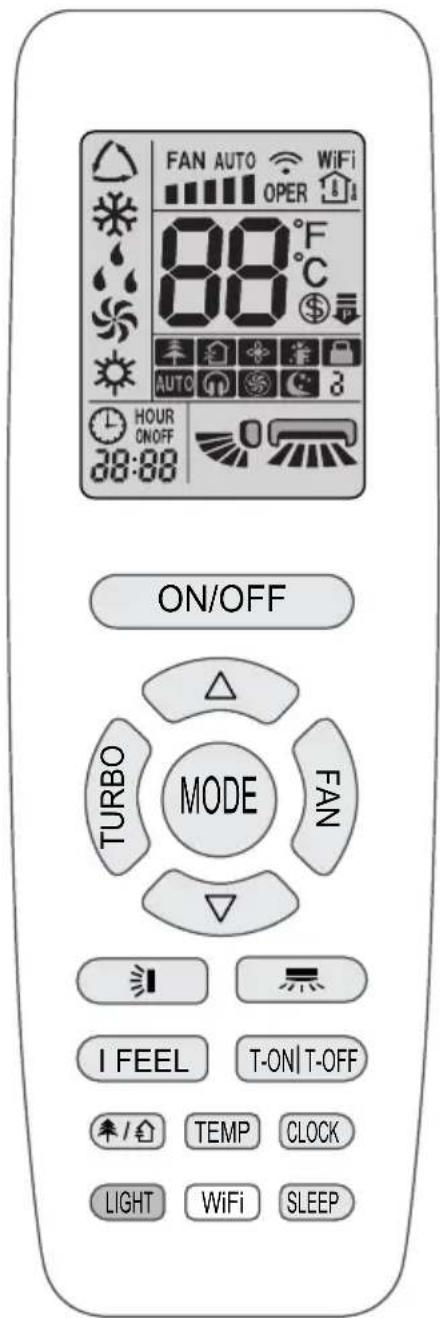
3 Operation of remote controller.... 4
3.1 Buttons on remote controller ....4
3.2 Introduction for icons on display screen....4
3.3 Introduction for buttons on remote controller.... 5
3.4 Function introduction for combination buttons....8
3.5 Replacement of batteries in remote controller....9
4 Preparative for Installation....10
4.1 Selection of the Installation Location 10
4.2 Connection Pipe Requirement ....1 1
4.3 Electrical Requirement ....1 2
5 Installation of the Unit....13
5.1 Installation of the Indoor Unit....13
5.2 Installation of the Connection Pipe 16
5.3 Vacuum and Gas Leakage Inspection 20
5.4 Installation of the Drain Hose 22
5.5 The Panel Installation 25
5.6 Electrical Wiring 27
6 Installation of Controller....30
7 Test Running ....30
7.1 Trial Operation and Testing 30
8 Troubleshooting and Maintenance 33
8.1 Troubleshooting 33
8.2 Routine Maintenance 34
9 Safety operation of flammable refrigerant 36
10. Specialist's Manual.... 38
This marking indicates that this product should not be disposed with other household wastes throughout the EU. To prevent possible harm to the environment or human health from uncontrolled waste disposal, recycle it responsibly to promote the sustainable reuse of material resources. To return your used device, please use the return and collection systems or contact the retailer where the product was purchased. They can take this product for environmental safe recycling.
R32: 675
Please read this operating manual carefully before operating the unit.

Appliance filled with flammable gas R32.

Before use the appliance, read the owner's manual first.

Before install the appliance, read the installation manual first.
Before repair the appliance, read the service manual first.
The figures in this manual may be different with the material objects, please refer to the material objects for reference.

The Refrigerant
- To realize the function of the air conditioner unit, a special refrigerant circulates in the system. The used refrigerant is the fluoride R32, which is specially cleaned. The refrigerant is flammable and inodorous. Furthermore, it can lead to explosion under certain conditions. But the flammability of the refrigerant is very low. It can be ignited only by fire.
- Compared to common refrigerants, R32 is a nonpolluting refrigerant with no harm to the ozonosphere. The influence upon the greenhouse effect is also lower. R32 has got very good thermodynamic features which lead to a really high energy efficiency. The units therefore need a less filling.
WARNING:
Do not use means to accelerate the defrosting process or to clean, other than those recommended by the manufacture. Should repair be necessary, contact your nearest authorized Service Centre. Any repairs carried out by unqualified personnel may be dangerous. The appliance shall be stored in a room without continuously operating ignition sources. (for example: open flames, an operating gas appliance or an operating electric heater.) Do not pierce or burn.
Appliance shall be installed, operated and stored in a room with a floor area larger than X m ^2 . (Please refer to table "a" in section of " Safety operation of flammable refrigerant " for Space X.)
Appliance filled with flammable gas R32. For repairs, strictly follow manufacturer's instructions only. Be aware that refrigerants may not contain an odour. Read specialist's manual.

1 Safety Precautions
 WARNING! WARNING! | This mark indicates procedures which, if improperly performed, might lead to the death or serious injury of the user. |
 CAUTION! CAUTION! | This mark indicates procedures which, if improperly performed, might possibly result in personal harm to the user, or damage to property. |
WARNING!
 | WARNING! | |
| (1) | This product can't be installed at corrosive, inflammable or explosive environment or the place with special requirements, such as kitchen. Otherwise, it will affect the normal operation or shorten the service life of the unit, or even cause fire hazard or serious injury. As for above special places, please adopt special air conditioner with anti-corrosive or anti-explosion function. | |
| (2) | Installation should be left to the dealer or another professional. Improper installation may cause water leakage, electrical shock, or fire. | |
| (3) | Install the air conditioner according to the instructions given in this manual. Incomplete installation may cause water leakage, electrical shock, or fire. | |
| (4) | Be sure to use the supplied or specified installation parts. Use of other parts may cause the unit to come to lose, water leakage, electrical shock, or fire. | |
| (5) | Install the air conditioner on a solid base that can support the weight of the unit. An inadequate base or incomplete installation may cause injury in the event the unit falls off the base. | |
| (6) | Electrical work should be carried out in accordance with the installation manual and the national electrical wiring rules or code of practice. Insufficient capacity or incomplete electrical work may cause electrical shock or fire. | |
| (7) | Be sure to use a dedicated power circuit. Never use a power supply shared by another appliance. | |
| (8) | For wiring, use a cable length enough to cover the entire distance with no connection. Do not use an extension cord. Do not put other loads on the power supply, use a dedicated power circuit. (Failure to do so may cause abnormal heat, electric shock or fire.) | |
| (9) | Use the specified types of wires for electrical connections between the indoor and outdoor units. Firmly clamp the interconnecting wires so their terminals receive no external stresses. Incomplete connections or clamping may cause terminal overheating or fire. | |
| (10) | After connecting interconnecting and supply wiring be sure to shape the cables so that they do not put undue force on the electrical covers or panels. Install covers over the wires. Incomplete cover installation may cause terminal overheating, electrical shock, or fire. | |
| (11) | If any refrigerant has leaked out during the installation work, ventilate the room. (The refrigerant produces a toxic gas if exposed to flames.) | |
| (12) | After all installation is complete, check to make sure that no refrigerant is leaking out. (The refrigerant produces a toxic gas if exposed to flames.) | |
| (13) | When installing or relocating the system, be sure to keep the refrigerant circuit free from substances other than the specified refrigerant (R32), such as air. (Any presence of air or other foreign substance in the refrigerant circuit causes an abnormal pressure rise or rupture, resulting in injury.) | |
| WARNING! |
| (14) During pump-down, stop the compressor before removing the refrigerant piping. If the compressor is still running and the stop valve is open during pump-down, air will be sucked in when the refrigerant piping is removed, causing abnormal pressure in the freezer cycle which will lead to breakage and even injury. |
| (15) During installation, attach the refrigerant piping securely before running the compressor. If the compressor is not attached and the stop valve is open during pump-down, air will be sucked in when the compressor is run, causing abnormal pressure in the freezer cycle which will lead to breakage and even injury. |
| (16) Be sure to establish an earth. Do not earth the unit to a utility pipe, arrester, or telephone earth. Incomplete earth may cause electrical shock, or fire. A high surge current from lightning or other sources may cause damage to the air conditioner. |
| (17) Be sure to install an earth leakage breaker. Failure to install an earth leakage breaker may result in electric shocks, or fire. |
| (18) This appliance can be used by children aged from 8 years and above and persons with reduced physical, sensory or mental capabilities or lack of experience and knowledge if they have been given supervision or instruction concerning use of the appliance in a safe way and understand the hazards involved. Children shall not play with the appliance. Cleaning and user maintenance shall not be made by children without supervision. |
| (19) This appliance is not intended for use by persons (including children) with reduced physical, sensory or mental capabilities, or lack of experience and knowledge, unless they have been given supervision or instruction concerning use of the appliance by a person responsible for their safety. Children should be supervised to ensure that they do not play with the appliance. |
| (20) If the supply cord is damaged, it must be replaced by the manufacturer, its service agent or similarly qualified persons in order to avoid a hazard. |
| (21) Correct Disposal of this product |
| CAUTION! |
| (1). Do not install the air conditioner in a place where there is danger of exposure to inflammable gas leakage. If the gas leaks and builds up around the unit, it may catch fire. |
| (2). Establish drain piping according to the instructions of this manual. Inadequate piping may cause flooding. |
| (3). Tighten the flare nut according to the specified method such as with a torque wrench. If the flare nut is tightened too hard, the flare nut may crack after a long time and cause refrigerant leakage. |
2 Outline of the Unit and Main Parts
Indoor
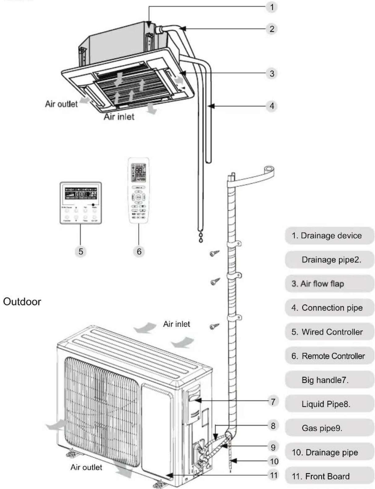
Fig.1
3. Operation and introduction of remote controller
3.1 Buttons on remote controller
3.2 Introduction for icons on display screen
| I feel | ||
| FAN AUTO | Set fan speed | |
| Turbo mode | ||
| Send signal | ||
| Operation mode | Auto mode | |
| Cool mode | ||
| Dry mode | ||
| Fan mode | ||
| Heat mode | ||
| Sleep mode | ||
| 8°C heating function | ||
| Power limiting operation | ||
| Health mode | ||
| Scavenging function | ||
| X-FAN function | ||
| Temp. display type | ||
| Indoor ambient temp. | ||
| Outdoor ambient temp. | ||
| Clock | ||
| Set temperature | ||
| WiFi | WiFi function | |
| 88:88 | Set time | |
| ON/OFF | TIMER ON / TIMER OFF | |
| Left & right swing | ||
| Up & down swing | ||
| Child lock | ||
| Quiet | ||
3.3 Introduction for buttons on remote controller
NOTE
- This is a general use remote controller. It could be used for the air conditioner with multifunction. For the functions which the model doesn't have, if press the corresponding button on the remote controller, the unit will keep the original running status.
- After putting through the power, the air conditioner will give out a sound. Power indicator "☐" is ON. After that, you can operate the air conditioner by using remote controller.
- Under on status, pressing the button on the remote controller, the signal icon " 🔺" on the display of remote controller will blink once and the air conditioner will give out a " di " sound, which means the signa has been sent to the air conditioner.
- As for the models with functions of WiFi or wired controller, the indoor unit must have been controlled by standard remote controller under auto mode first, and then the function of adjustable temperature under auto mode can be realized by APP or the wired controller.
- This remote controller can adjust the temperature under auto mode. When matching with the unit which is without the function of adjustable temperature under auto mode, the set temperature under auto mode may be invalid, or the displayed set temperature on the unit is not same as that on the remote controller under auto mode.
ON/OFF
Press this button to turn on the unit. Press this button again to turn off the unit.
MODE
Press this button to select your required operation mode.
AUTO COOL DRY FAN HEAT

- When selecting auto mode, air conditioner will operate automatically according to ex-factory setting. Press "FAN" button can adjust fan speed. Press "=" / "=" button can adjust fan blowing angle.
- After selecting cool mode, air conditioner will operate under cool mode. Press "△" or "▽" button to adjust set temperature. Press "FAN" button to adjust fan speed. Press "=" / "+" button to adjust fan blowing angle.
- When selecting dry mode, the air conditioner operates at low speed under dry mode. Under dry mode, fan speed can't be adjusted. Press " &= "/ " &= " button to adjust fan blowing angle.
- When selecting fan mode, the air conditioner will only blow fan, no cooling and no heating. All indicators are OFF. Press "FAN" button to adjust fan speed. Press " &= / " &= " button to
- When selecting heating mode, the air conditioner operates under heat mode. Press "△" or "▽" button to adjust set temperature. Press "FAN" button to adjust fan speed. Press "=" / "=" button to adjust fan blowing angle. (Cooling only unit won't receive heating mode signal. If setting heat mode with remote controller, press ON/OFF button can't start up the unit).
NOTE
- For preventing cold air, after starting up heating mode, indoor unit will delay 1\~5 minutes to blow air (actual delay time is depend on indoor ambient temperature).
- Set temperature range from remote controller: 16\~30°C (61-86°F);
- Under auto mode, temperature can be displayed; Under auto mode, set temperature can be adjusted.
- This mode indicator is not available for some models.
FAN
This button is used for setting Fan Speed in the sequence that goes from AUTO, 📷, ■, ■■
NOTE
- Under AUTO speed, air conditioner will select proper fan speed automatically according to factory default setting.
- It's low fan speed under dry mode.
- X-FAN function: Holding fan speed button for 2s in cool or dry mode, the icon " ✉ " is displayed and the indoor fan will continue operation for a few minutes in order to dry the indoor unit even though you have turned off the unit. After energization, X-FAN OFF is defaulted. X-FAN is not available in auto, fan or heat mode.
This function indicates that moisture on evaporator of indoor unit will be blown after the unit is stopped to avoid mould. - Having set X-FAN function on: After turning off the unit by pressing ON/OFF button, indoor fan will continue running for a few minutes at low speed. In this period, ho ld fan speed button for 2s to stop indoor fan directly.
Having set X-FAN function off: After turning off the unit by pressing ON/OFF button, the complete unit will be off directly.
TURBO
Under COOL or HEAT mode, press this button to
turn to quick COOL or quick HEAT mode. " 🔊" icon is displayed on remote controller. Press this button again to exit turbo function and " 🔊" icon will disappear. If start this function, the unit will run at super-high fan speed to cool or heat quickly so that the ambient temperature approaches the preset temperature as soon as possible.
△/▽
- Press "△or" ▼ button once increase or decrease set temperature 1 ℃ (°F). Holding "△or" ▼ button, 2s later, set temperature on remote controller will change quickly. On releasing button after setting is finished, temperature indicator on indoor unit will change accordingly.
- When setting T-ON, T-OFF or CLOCK, press "△" or "▽" button to adjust time. (Refer to CLOCK, T-ON, T-OFF buttons)

Press this button can select left & right swing angle. Fan blow angle can be selected circularly as below:
flowchart
graph TD
    A["Start"] --> B["Step 1"]
    B --> C["Step 2"]
    C --> D["Step 3"]
    D --> E["Step 4"]
    E --> F["Step 5"]
    F --> G["Step 6"]
    G --> H["Step 7"]
    H --> I["Step 8"]
    I --> J["Step 9"]
    J --> K["Step 10"]
    K --> L["Step 11"]
    L --> M["Step 12"]
    M --> N["Step 13"]
    N --> O["Step 14"]
    O --> P["Step 15"]
    P --> Q["Step 16"]
    Q --> R["Step 17"]
    R --> S["Step 18"]
    S --> T["Step 19"]
    T --> U["Step 20"]
    U --> V["Step 21"]
    V --> W["Step 22"]
    W --> X["Step 23"]
    X --> Y["Step 24"]
    Y --> Z["Step 25"]
NOTE
- Press this button continuously more than 2s, the main unit will swing back and forth from left to right, and then loosen the button, the unit will stop swinging and present position of guide louver will be kept immediately.
- Under left and right swing mode, when the status is switched from off to ☐, if press this button again 2s later, ☐status will switch t o off status directly; if press this button again within 2s, the change of swing status will also depend on the circulation sequence stated above.
- The function is only available for some models.
[NO TEXT]
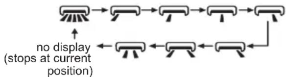
Press this button can select up & down swing angle. Fan blow angle can be selected circularly as below:
![DAITSU DUF 18K - [NO TEXT] - 1](/content/2026/06/1175542/images/f4468d020450abb11b7f3394692a9cbb6a6dbc60ef15e72ebc9b412a2753393f.jpg)
flowchart
graph LR
    A["0"] --> B["-0"] --> C["-0"] --> D["0"] --> E["0"]
    F["0"] <--_G["0"] <--_H["0"] <--_I["0"] <--_J["0"]
    style A fill:#f9f,stroke:#333
    style B fill:#f9f,stroke:#333
    style C fill:#f9f,stroke:#333
    style D fill:#f9f,stroke:#333
    style E fill:#f9f,stroke:#333
    style F fill:#f9f,stroke:#333
    style G fill:#f9f,stroke:#333
    note right of F: (horizontal louvers stops at current position)
- When selecting " 🔍", air conditioner is blowing fan automatically. Horizontal louver will automat-
ically swing up & down at maximum angle.
- When selecting "-0, -0, -0, 0, 0", air conditioner is blowing fan at fixed position. Horizontal louver will stop at the fixed position.
- When selecting "air conditioner is blowing fan at fixed angle. Horizontal louver will send air at the fixed angle.
- Hold "0" button above 2s to set your required swing angle. When reaching your required angle, release the button.
NOTE
- “0, 0, 0” may not be available. When air conditioner receives this signal, the air conditioner will blow fan automatically.
- Press this button continuously for more than 2s, the main unit will swing back and forth from up to down, and then loosen the button, the unit present position of guide louver will be kept immediately.
- Under up and down swing mode, when the status is switched from off to 0, if press this button again 2s later, 0 status will switch to off status directly; if press this button again within 2s, the change of swing status will also depend on the circulation sequence stated above.
T-ON|T-OFF
- T-ON button
"T-ON" button can set the time for timer on. After pressing this button, " ⏻ " icon disappears and the word "ON" on remote controller blinks. Press "△ or "▽ " button to adjust T-ON setting. After each pressing "△ " or "▽ " button, T-ON setting will increase or decrease 1min. Hold "△ " or "▽ " button, 2s later, the time will change quickly until reaching your required time. Press "T-ON " to confirm it. The word "ON" will stop blinking. " ⏻ " icon resumes displaying. Cancel T-ON: Under the condition that T-ON is started up, press "T-ON" button to cancel it.
- T-OFF button
"T-OFF" button can set the time for timer off. After pressing this button, " 🔒" icon disappears and the word "OFF" on remote controller blinks. Press "△or " ▼button to adjust T-OFF setting. After each pressing "△" or "▽" button, T-OFF setting will increase or decrease 1min. Hold "△ or "▽" button, 2s later, the time will change quickly until reaching your required time. Press "T-OFF" word "OFF" will stop blinking. " 🔒" icon resumes displaying. Cancel T-OFF. Under the condition that T-OFF is started up, press "T-OFF" button to cancel it.
NOTE
- Under on and off status, you can set T-OFF or T-ON simultaneously.
- Before setting T-ON or T-OFF, please adjust the clock time.
- After starting up T-ON or T-OFF, set the constant circulating valid.
- After that, air conditioner will be turned on or turned off according to setting time. ON/OFF button has no effect on setting. If you don't need this function, please use remote controller to cancel it.
I FEEL
Press this button to start I FEEL function and "F" will be displayed on the remote controller. After this function is set, the remote controller will send the detected ambient temperature to the controller and the unit will automatically adjust the indoor temperature according to the detected temperature. Press this button again to cancel I FEEL function and "F" will disappear.
- Please put the remote controller near user when this function is set. Do not put the remote controller near the object of high temperature or low temperature in order to avoid detecting inaccurate ambient temperature. When I FEEL function is turned on, the remote controller should be put within the area where indoor unit can receive the signal sent by the remote controller.
CLOCK
Press this button to set clock time. " 🔒 icon on remote controller will blink. Press " " or " " ▼ button within 5s to set clock time. Each pressing of "△ or " " button, clock time will increase or decrease 1 min. If hold "△ or " " button, 2s later, time will change quickly. Release this button when reaching your required time. Press "CLOCK" button to confirm the time. " 🔒" icon stops blinking.
NOTE
- Clock time adopts 24-hour mode.
- The interval between two operations can 't exceed 5s.
Otherwise, remote controller will quit setting status. Operation for TIMER ON/TIMER OFF is the same.
SLEEP
- Press this button, can select Sleep 1 ( Ⓞ1), Sleep 2 ( Ⓞ2), Sleep 3 ( Ⓞ3) and cancel the
Sleep, circulate between these, after electrified, Sleep Cancel is defaulted.
- Sleep 1 is Sleep mode 1, in Cool modes; sleep status after run for one hour, the main unit setting temperature will increase 1, two hours, setting temperature increased 2^ , then the unit will run at this setting temperature; In Heat mode: sleep status after run for one hour, the setting temperature will decrease 1, two hours, setting temperature will decrease 2, then the unit will run at this setting temperature.
- Sleep 2 is sleep mode 2, that is air conditioner will run according to the presetting a group of sleep temperature curve.
- Sleep 3-the sleep curve setting under Sleep mode by DIY;
(1) Under Sleep 3 mode, press "Turbo" button for a long time, remote controller enters into user individuation sleep setting status, at this time, the time of remote controller will display "1hour", the setting temperature "88" will display the corresponding temperature of last setting sleep curve and blink (The first entering will display according to the initial curve setting value of original factory);
(2) Adjust “△” and “▽” button, could change the corresponding setting temperature, after adjusted, press “Turbo” button for confirmation;
(3) At this time, 1 hour will be automatically increased at the timer position on the remote control, (that are "2 hours" or "3 hours" or "8 hours"), the place of setting temperature "88" will display the corresponding temperature of last setting sleep curve and blink;
(4) Repeat the above step (2)\~(3) operation, until 8 hours temperature setting finished, sleep, curve setting finished, at this time, the remote controller will resume the original timer display; temperature display will resume to original setting temperature.
- Sleep3- the sleep curve setting under Sleep mode by DIY could be inquired:
The user could accord to sleep curve setting method to inquire the presetting sleep curve, enter into user individuation sleep setting status, but do not change the temperature, press "Turbo" button directly for confirmation. Note: In the above presetting or enquiry procedure, if continuously within 10s, there is no button pressed, the sleep curve setting within 10s, there is no button pressed, the sleep curve setting status will be automatically quit and resume to display the original displaying. In the presetting or enquiry procedure, press "ON/OFF" button, "Mode" button, "Sleep" button, the sleep curve setting or enquiry status will quit similarly.
WiFi
Press "WiFi" button to turn on WiFi function, "WiFi" icon will be displayed on the remote controller;
Hold "WiFi" button for 5s to turn off WiFi function and "WiFi" icon will disappear.
Under off status, press "MODE" and "WiFi" buttons simultaneously for 1s, WiFi module will restore factory settings.
NOTE
- The function is only available for some models.
1
Press this button to turn on or turn off the health and scavenging functions in operation status. Press this button for the first time to start scavenging function; LCD displays " 🔊". Press the button for the second time to start health and scavenging functions; LCD displays " 🔊 " and " 🔊 ". Press this button for the third time to quit health and scavenging functions simultaneously. Press the button for the fourth time to start health function; LCD display " 🔊 ". Press this button again to repeat the operation above.
NOTE
- The function is only available for some models.
LIGHT
Press this button to turn off display light on indoor unit. "💡" icon on remote controller disappears.
Press this button again to turn on display light.
"💡 " icon is displayed.
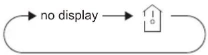
TEMP
Press this button, you can see indoor set temperature, indoor ambient temperature on indoor unit's display. The setting on remote controller is selected circularly as below:
flowchart
graph LR
    A["no display"] --> B["House Icon"]
3.4 Function introduction for combination buttons
Energy-saving function
Under cooling mode, press "TEMP" and "CLOCK" buttons simultaneously to start up or turn off energy-saving function. When energy-saving function is started up, "SE" will be shown on remote controller, and air conditioner will adjust the set temperature automatically according to ex-factory setting to reach to the best energy-saving effect. Press "TEMP" and "CLOCK" buttons simultaneously again to exit energy-saving function.
NOTE
- Under energy-saving function, fan speed is defaulted at auto speed and it can't be adjusted.
- Under energy-saving function, set temperature can 't be adjusted. Press "TURBO" button and the remote controller won't send signal.
- Sleep function and energy-saving function can't operate at the same time. If energy-saving function has been set under cool mode, press SLEEP button will cancel energy-saving function. If sleep function has been set under cool mode, start up the energy-saving function will cancel sleep function.
8°C heating function
Under heat mode, press "TEMP" and "CLOCK" buttons simultaneously to start up or turn off 8 °C heating function. When this function is started up, " \$ " and "8°C" will be shown on remote controller, and the air conditioner keep the heating status at 8°C. Press "TEMP" and "CLOCK" buttons simultaneously again to exit 8°C heating function.
NOTE
- Under 8°C heating function, fan speed is defaulted at auto speed and it can't be adjusted.
- Under 8°C heating function, set temperature can 't be adjusted. Press "TURBO" button and the remote controller won't send signal.
- Sleep function and 8°C heating function can 't operate at the same time. If 8°C heating function has been set under heat mode, press SLEEP button will cancel 8°C heating function. If sleep function has been set under heat mode, start up the 8 °C heating function will cancel sleep function.
- Under °F temperature display, the remote controller will display 46°F heating.
Child lock function
Press "△" and "▽" simultaneously to turn on or turn off child lock function. When child lock function is on, "■" icon is displayed on remote controller. If you operate the remote controller, the "■" icon will blink three times without sending signal to the unit.
Temperature display switchover function
Under OFF status, press "▽" and "MODE" buttons simultaneously to switch temperature display between °C and °F.
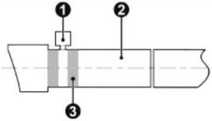
3.5 Replacement of batteries in remote controller
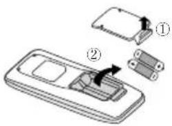
Fig.1
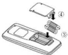
Fig.2
- Lift the cover along the direction of arrow (as shown in Fig 1 ①).
- Take out the original batteries (as shown in Fig 1 ②).
- Place two 7# (AAA 1.5V) dry batteries, and make sure the position of “+” polar and “-” polar is correct (as shown in Fig 2 ③).
- Reinstall the cover (as shown in Fig 2 ④).
NOTICE
- During operation, point the remote control signal sender at the receiving window on indoor unit.
- The distance between signal sender and receiving window should be no more than 8m, and there should be no obstacles between them.
- Signal may be interfered easily in the room where there is fluorescent lamp or wireless telephone; remote controller should be close to indoor unit during operation.
- Replace new batteries of the same model when replacement is required.
- When you don't use remote controller for a long time, please take out the batteries.
- If the display on remote controller is fuzzy or there's no display, please replace batteries.
4 Preparative for Installation
4.1 Selection of the Installation Location
| WARNING! |
| The unit must be installed where strong enough to withstand the weight of the unit and fixed securely, otherwise the unit would topple or fall off. |
| 1 Do not install where there is the danger of combustible gas leakage. |
| 2 Do not install the unit near heat source of heat, steam, or flammable gas. |
| 3 Children under 10 years old must be supervised not to operate the unit. |
Decide the installation location with the customer as follows:
4.1.1 Indoor Unit
Select an installation site where the following conditions are fulfilled and that meets your customer's approval.
(1). Obstruct should be put away from the intake or outlet vent of the indoor unit so that the airflow can be blown through all the room.
(2). Make sure that the installation meets the requirement of the schematic diagram of installation spaces.
(3). Select the place where can stand 4 times of the weight of the indoor unit and would not increase the operating noise and vibration.
(4). The horizontality of the installation place should be guaranteed.
(5). Select the place where is easy to drain out the condensate water, and connect with outdoor unit.
(6). Make sure that there are enough space for care and maintenance, and the height fall between the indoor unit and ground is above 2500mm.
(7). When installing the suspension bolt, check if the installation place can stand 4 times of the weight of the unit. If not, reinforce it before installation.
Note: There will be large amount of greasy dirt accumulated on the fan, heat exchanger and water pump located in the dinning room and kitchen, which would reduce the capacity of the heater exchanger, lead to leakage and abnormal operation of the water pump.
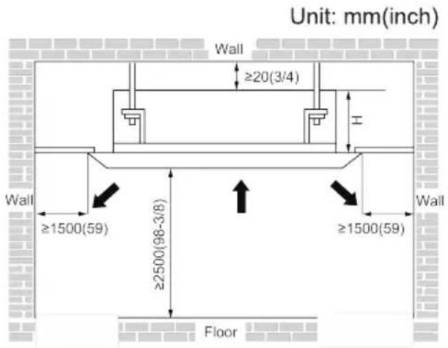
Fig.2
Table 2
4.2 Connection Pipe Requirement
| CAUTION! |
| The maximum length of the connection pipe is listed in the table below. Do not place the units between which the distance exceeds the maximum length of the connection pipe. |
Table 3
| Model\Item | Size of Fitting Pipe(Inch) | Drainage pipe(Outer Diameter × wall thickness) (mm) | |
| Liquid | Gas | ||
| 12K | 1/4 | 3/8 | Φ25×1.5 |
| 18K | 1/2 | ||
| 24K | 5/8 | ||
The connection pipe should be insulated with proper water-proof insulating material.
The pipe wall thickness shall be 0.5-1.0mm and the pipe wall shall be able to withstand the pressure of 6.0 MPa. The longer the connecting pipe, the lower the cooling and heating effect performs.
4.3 Electrical Requirement
Electric Wire Size and Fuse Capacity.
Table 4
| Indoor Units | Power Supply | Fuse Capacity | Min. Power Supply Cord |
| V/Ph/Hz | A | mm^2 | |
| 12~18K | 220-240V~50Hz | 3.15 | 4x0.75 |
| 24K | 5 |
Notes:
①. The fuse is located on the main board.
②. Install the disconnect device with a contact gap of at least 3mm in all poles nearby the units (Both indoor unit and outdoor unit). The appliance must be positioned so that the plug is accessible.
③ The specifications of the power cable listed in the table above are determined based on the maximum power (maximum amps) of the unit.
④ The specifications of the power cable listed in the table above are applied to the conduit-guarded multi-wire copper cable (like, YJV copper cable, consisting of PE insulated wires and a PVC cable jacket) used at 40°C and resistible to 90°C(see IEC 60364-5-52). If the working condition changes, they should be modified according to the related national standard.
5 Installation of the Unit
5.1 Installation of the Indoor Unit
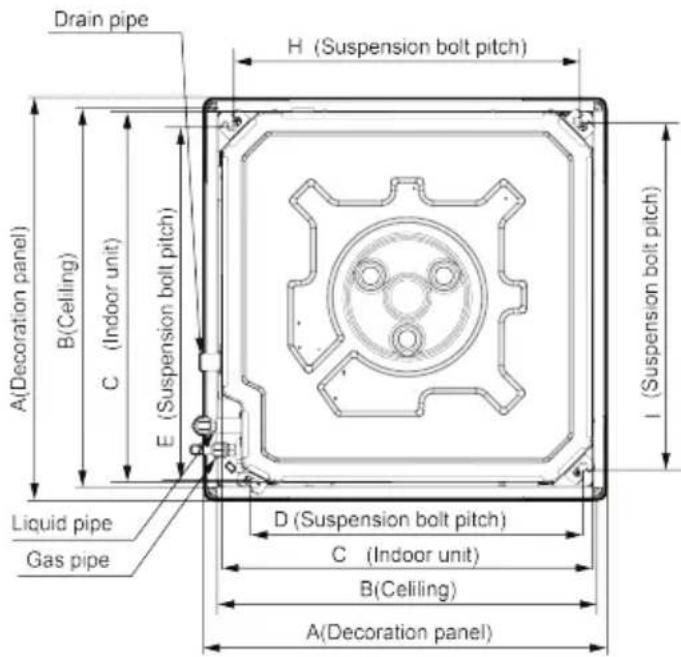
5.1.1 Indoor unit dimension
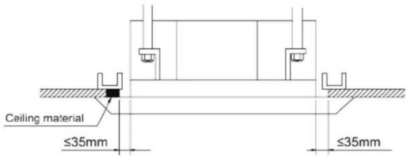
In order to make the front panel cover 20mm of the ceiling, the distance between the ceiling and the unit should be 35mm or less. If the distance between the ceiling and the unit is above 35mm, add some ceiling material to shorten the distance. See the following diagram.
For the units: 12-18k
natural_image
Technical line drawing of a mechanical housing or enclosure with dimension annotations (no readable text or symbols)Fig.3
Table 5
Unit: mm
| DimensionsModel | A | B | C | D | E | F | G | H | I |
| 12K | 620 | 580 57 | 0 505 | 550 2 | 65 140 | 530 | 530 | ||
| 18K | 620 | 580 57 | 0 505 | 550 2 | 65 140 | 530 | 530 |
For the units: 24k
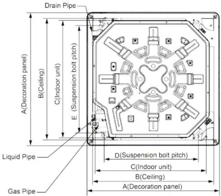
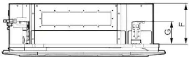
Fig.3
Table 5
Unit: mm
| Model\Dimensions | A B | C D E | F G | ||||
| 24K | 950 | 870 | 840 680 | 780 24 | 0 135 |
5.1.2 Installing the Main Body Unit
![Nut (field supplied) Gasket (attachment) Hoisting stand Tighten (double nuts) [Fix the hoisting stand firmly] Insert Gasket anchor board (attachment) [Fix the gasket firmly] Center of the ceiling opening Water level Polyethylene pipe Paper template Bolt(attachment) Bolt(attachment) [Fix the paper template] One bolt located at one corner of the outlet pipe should be fixed on one corner of the drainage slot.](/content/2026/06/1175542/images/b6f6eda85b9a334870907b6abf2982f89a4652a6a8ad191efe0cd96d516039bf.jpg)
Fig.4
(1). Install the hoisting stand on the hoisting screw by using nuts and gaskets at both the upper and lower sides of the hoisting stand. To prevent the gasket from breaking off, a gasket anchor board can be helpful.
(2). Install the paper template on the unit, and fix the drain pipe at the outlet vent.
(3). Adjust the unit to the best position.
(4). Check if the unit is installed horizontally at four directions. If not, the water pump and the float switch would function improperly and even lead to water leakage.
(5). Remove the gasket anchor board and tighten the nut remained.
(6). Remove the paper template.
Notes:
- Drilling of ceiling opening and installation of air conditioner must be performed by professionals!
- Please refer to the installation cardboard for the dimension of drilling hole of lifting screw of cassette unit.
5.1.3 Installing the Suspension Bolts
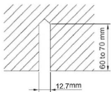
(1). Using the installation template, drill holes for bolts (four holes). (Fig. 5)
(2). Install the bolts to the ceiling at a place strong enough to hang the unit. Mark the bolt positions from the installation template. With a concrete drill, drill for 12.7mm diameter holes. (Fig.6)
(3). Insert the anchor bolts into the drilled holes, and drive the pins completely into the anchor bolts with a hammer. (Fig.7)
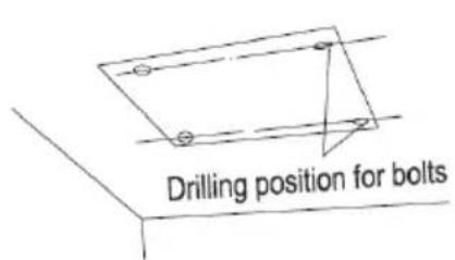
Fig.5 Fig.6
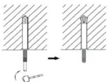
natural_image
Diagram showing two mechanical components with a tool, one being inserted and the other being inserted into a housing (no text or symbols present)Fig.7
5.1.4 Leveling
The water level test must be done after installing the indoor unit to make the unit is horizontal, as shown below.
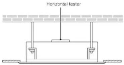
Fig.8
5.2 Installation of the Connection Pipe
5.2.1 Flare Processing
(1). Cut the connection pipe with the pipe cutter and remove the burrs.
(2). Hold the pipe downward to prevent cuttings from entering the pipe.
(3). Remove the flare nuts at the stop valve of the outdoor unit and inside the accessory bag of the indoor unit, then insert them to the connection pipe, after that, flare the connection pipe with a flaring tool.
(4). Check if the flare part is spread evenly and there are no cracks (see Fig.9).
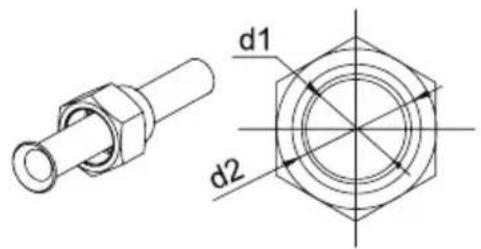
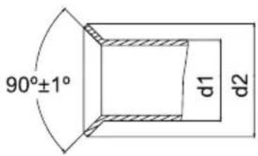
Fig.9
5.2.2 Bending Pipes
(1). The pipes are shaped by your hands. Be careful not to collapse them.
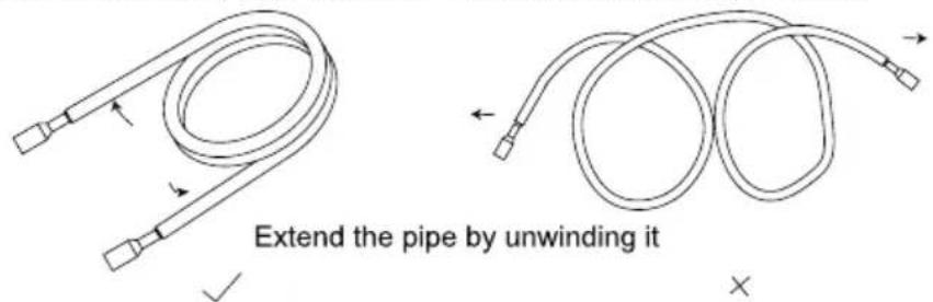
Fig.10
(2). Do not bend the pipes in an angle more than 90^ .
(3). When pipes are repeatedly bent or stretched, the material will harden, making it difficult to bend or stretch them any more. Do not bend or stretch the pipes more than three times.
(4). When bending the pipe, do not bend it as is. The pipe
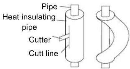
Fig.11
will be collapsed. In this case, cut the heat insulating pipe with a sharp cutter as shown in Fig.11, and bend it after exposing the pipe. After bending the pipe as you want, be sure to put the heat insulating pipe back on the pipe, and secure it with tape.
| CAUTION! |
| 1 To prevent breaking of the pipe, avoid sharp bends. Bend the pipe with a radius of curvature of 150 mm or over. |
| 2 If the pipe is bent repeatedly at the same place, it will break. |
5.2.3 Connecting the Pipe at the Indoor Unit Side
Detach the caps and plugs from the pipes.
| CAUTION! |
| 1 Be sure to apply the pipe against the port on the indoor unit correctly. If the centering is improper, the flare nut cannot be tightened smoothly. If the flare nut is forced to turn, the threads will be damaged. |
| 2 Do not remove the flare nut until the connection pipe is to be connected so as to prevent dust and impurities from coming into the pipe system. |
When connecting the pipe to the unit or removing it from the unit, please do use both the spanner and the torque wrench.(Fig.12)
When connecting, smear both inside and outside of the flare nut with refrigeration oil, screw it hand tight and then tighten it with the spanner.
Refer to Table 6 to check if the wrench has been tightened properly (too tight would mangle the nut and lead to leakage).
Examine the connection pipe to see if it leaks, then take the treatment of heat insulation, as shown in the Fig.12.
Use the medium-sized sponge to insulate the coupler of the gas pipe.
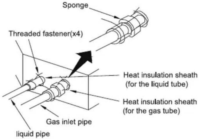
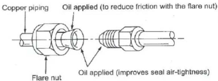
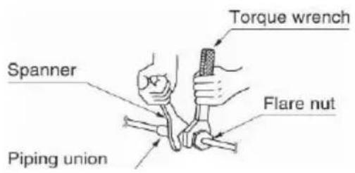
Fig.12
Table 6 Flare nut tightening torque
| Pipe Diameter(inch) | Tightening Torque(N·m) |
| 1/4 15-30 | |
| 3/8 35-40 | |
| 5/8 | 60-65 |
| 1/2 45-50 | |
| 3/4 70-75 | |
| 7/8 80-85 |
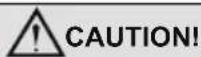
Be sure to connect the gas pipe after connecting the liquid pipe completely.
5.2.4 Connecting the Pipe at the Outdoor Side Unit
Tighten the flare nut of the connection pipe at the outdoor unit valve connector. The tightening method is the same as that as at the indoor side.
5.2.5 Checking the Pipe Connections for Gas Leaking
For both indoor and outdoor unit side, check the joints for gas leaking by the use of a gas leakage detector without fail when the pipes are connected.
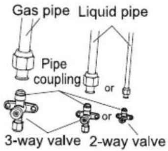
Fig.13
5.2.6 Heat Insulation on the Pipe Joints (Indoor Side Only)
Stick coupler heat insulation (large and small) to the place where connecting pipes.
Fig.14
5.2.7 Liquid Pipe and Drain Pipe
If the outdoor unit is installed lower than the indoor unit (See Fig.15)
(1). A drain pipe should be above ground and the end of the pipe does not dip into water. All pipes must be restrained to the wall by saddles.
(2). Taping pipes must be done from bottom to top.
(3). All pipes are bound together by tape and restrained to wall by saddles.
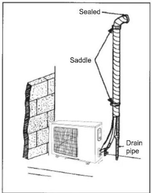
Fig.15
If the outdoor unit is installed higher than the indoor unit (See Fig.16)
(1). Taping should be done from lower to the upper part.
(2). All pipes are bound and taped together and also should be trapped to prevent water from returning to the room.
(3). Restraint all pipes to the wall with saddles.
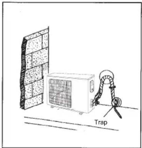
natural_image
Diagram of a wall-mounted air conditioner unit connected to a rope trap, with no visible text or symbols.Fig.16
5.3 Vacuum and Gas Leakage Inspection

CAUTION!
Do not purge the air with refrigerants but use a vacuum pump to vacuum the installation! There is no extra refrigerant in the outdoor unit for air purging!
5.3.1 Vacuum
(1). Remove the caps of the liquid valve, gas valve and also the service port.
(2). Connect the hose at the low pressure side of the manifold valve assembly to the service port of the unit's gas valve, and meanwhile the gas and liquid valves should be kept closed in case of refrigerant leak.
(3). Connect the hose used for evacuation to the vacuum pump.
(4). Open the switch at the lower pressure side of the manifold valve assembly and start the vacuum pump. Meanwhile, the switch at the high pressure side of the manifold valve assembly should be kept closed, otherwise evacuation would fail.
(5). The evacuation duration depends on the unit's capacity, generally, 15 minutes for the 12K units, 20 minutes for the 18K units, 30 minutes for the 24K units. And verify if the pressure gauge at the low pressure side of the manifold valve assembly reads -0.1MPa (-750mmHg), if not, it indicates there is leak somewhere. Then, close the switch fully and then stop the vacuum pump.
(6). Wait for some time to see if the system pressure can remain unchanged, 3 minutes for the units less than 18K, 5 minutes for the 18K\~24K units. During this time, the reading of the pressure gauge at the low pressure side can not be larger than 0.005MPa (37.5mmHg).
(7). Slightly open the liquid valve and let some refrigerant go to the connection pipe to balance the pressure inside and outside of the connection pipe, so that air will not come into the connection pipe when removing the hose. Note that the gas and liquid valve can be opened fully only after the manifold valve assembly is removed.
(8). Place back the caps of the liquid valve, gas valve and also the service port.
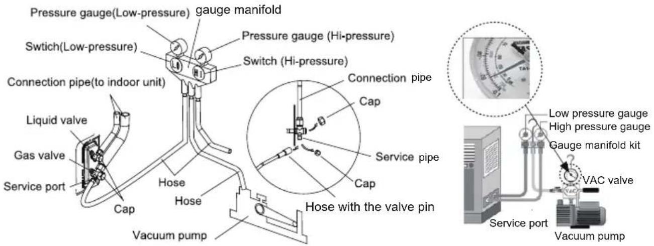
Fig.17
Note: For the large-sized unit, it has the service port for both the gas valve and the liquid valve. During evacuation, it is available to connect two hoses of the manifold valve assembly to two service ports to quicken the evacuating speed.
5.4 Installation of the Drain Pipe
(1). It is not allowed to connect the condensate drain pipe into waste pipe or other pipelines which are likely to produce corrosive or peculiar smell to prevent the smell from entering indoors or corrupt the unit.
(2). It is not allowed to connect the condensate drain pipe into rain pipe to prevent rain water from pouring in and cause property loss or personal injury.
(3). Condensate drain pipe should be connected into special drain system for air conditioner.
5.4.1 Installation of Drain Pipe
(1). Keep piping as short as possible and slope it downwards at a gradient of at least 1/100 so that air may not remain trapped inside the pipe.
(2). Keep pipe size equal to or greater than that of the connecting pipe.
(3). Install the drain piping as shown and take measures against condensation. Improperly rigged piping could lead to leaks and eventually wet furniture and belongings.
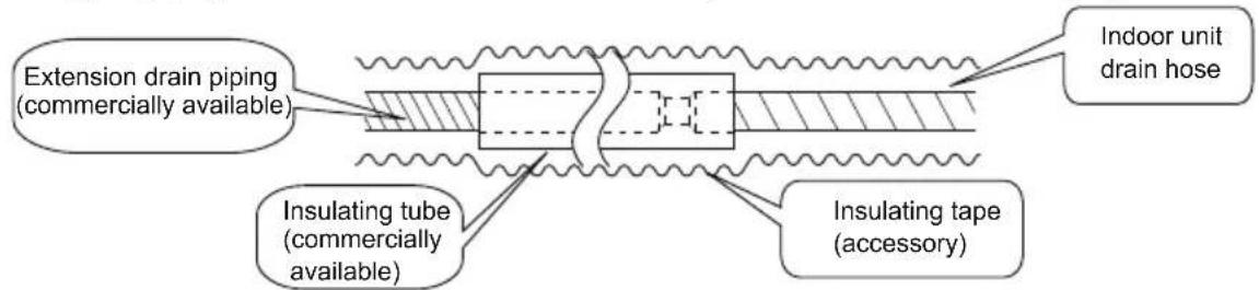
Fig.19
5.4.2 Installing the Drain Pipe
(1). Insert the drain pipe to the drain outlet of the unit and then tighten the clamp securely with tape.
(2). Connect the extension drain pipe to the drain pipe and then tighten the clamp with tape.
 | 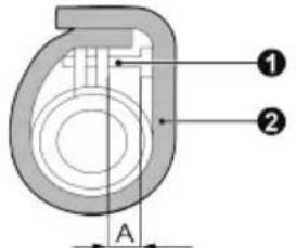 |
| Insulate the pipe clamp and the drain hose using heat insulation sponge.1 Metal clamp2 Drain hose3 Small sponge | During the installation, distance from soft drain pipe to the gasket is 15±3mm when the bolt is tightened. It is not allowed to apply PVC or other related glue in the joints of two ends of drain pipe.1 Metal clamp2 Large sponge |
| Indoor Unit | A |
| 12K、18K | ≤12 mm |
| 24K | ≤15 mm |
(3). When unifying multiple drain pipes, install the pipes as Fig.20. Select converging drain pipes whose gauge is suitable for the operating capacity of the unit. (take the cassette type unit for example)
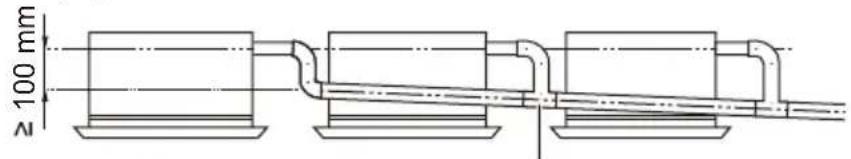
T-joint converging drain pipes

T-joint converging drain pipes
Fig.20
(4). When the drain hose cannot keep a sufficient gradient, it is necessary to fit a riser pipe (field supplied) to it.
(5). If the air flow of indoor unit is high, this might cause negative pressure and result in return suction of outdoor air. Therefore, U-type water trap shall be designed on the drainage side of each indoor unit.(Fig.21)
(6). Install one water trap for each unit.
(7). Installation of water trap shall consider easy cleaning in the future.
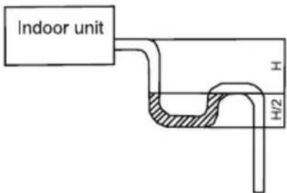
Fig.21
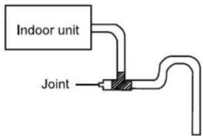
Fig.22
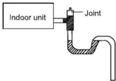
Fig.23
(8). Connection of drainage branch pipe to the standpipe or horizontal pipe of drainage main pipe
The horizontal pipe cannot be connected to the vertical pipe at a same height. It can be connected in a manner as shown below:
No.1: Attach the 3-way connection of the drainage pipe joint as shown in Fig.24.
No.2: Attach the drain elbow as shown in Fig.25.
No.3: Attach the horizontal pipe as shown in Fig.26.
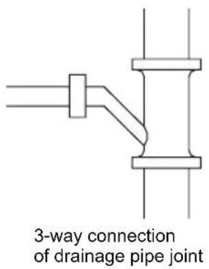
Fig.24
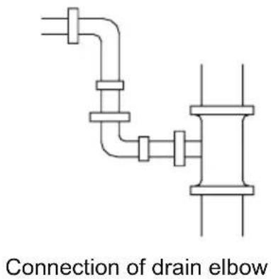
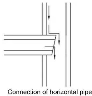
Fig.26Fig.25
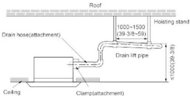
5.4.3 Precautions When Doing Riser Piping Work
(1). Make sure that heat insulation work is executed on the following 2 spots to prevent any possible water leakage due to dew condensation.
1). Connect the drain hose to the drain lift pipe, and insulate them.
2). Connect the drain hose to the drain outlet on the indoor unit, and tighten it with the clamp.
Unit: mm(inch)
Fig.27
(4). Secure a downward gradient of 1/100 or more for the drain pipe. To accomplish this, mount supporting brackets at an interval of 1 -1.5 m.
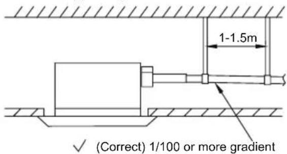
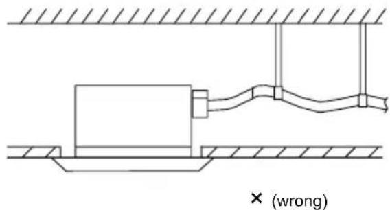
Fig.28
(5). The incline of attached drain hose should be 75 mm or less so that the drain outlet does not have to withstand additional force.
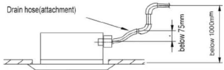
Fig.29
5.4.4 Check Drainage
After the pipeline work is finished, check whether the drainage can go smoothly.
(1) Add slowly about 1L of water into the water tray. After the electric circuit is completed, check the drainage condition during refrigerating operation.
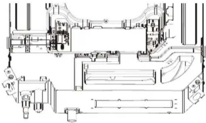
natural_image
Technical line drawing of a mechanical assembly with no visible text or symbolsSingle-phase units(12\~24k)
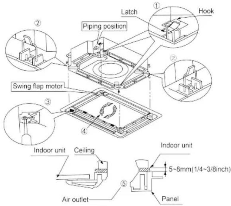
5.5 Installing the Front Panel
As shown below, take off the 4 corner covers from the front panel and loose the hexagon screw bolts on the 4 fasteners to the maximum. The position marked with "PIPING SIDE" on the front panel will direct right at the pipe mouth of the indoor unit.
(1) Temporarily hang the 4 fasteners on the corresponding hooks of the main body of the indoor unit (Do not let the conducting wires get involved into the sealing material).
(2) Screw in the hexagon screws beneath the 4 fasteners by about 15mm (Front panel will rise).
(3) As shown below, turn the front panel according to the arrow direction so that the front panel can be well connected with the ceiling.
(4) Screw up the screws until the thickness of the sealing material between the front panel and the ceiling is 5-8mm.

NOTES:
(1) Improper screw looseness will lead to the following problem.
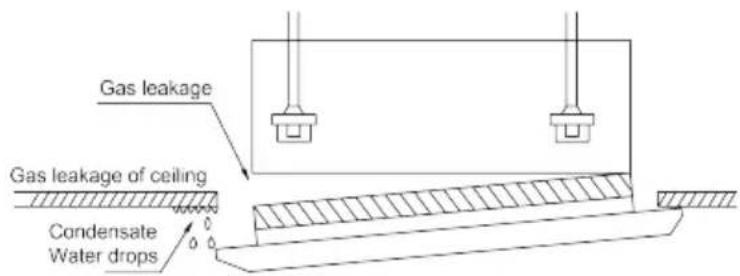
(2) After the screws are tightened, if there is still a gap between the ceiling and the decorative front panel, adjust the height of the unit again (as shown below).
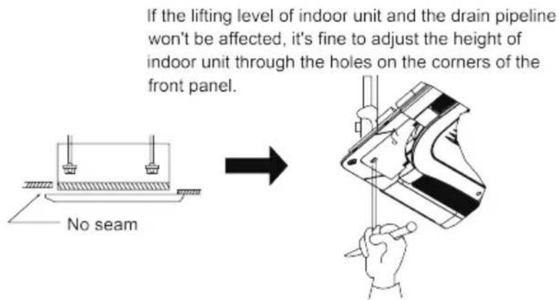
(3) After installing the front panel, make sure there's no gap between the unit and the front panel.
(4) Circuit of the decorative front panel.
(5) Connect the front panel to the main body through the corresponding slots. Match the slots according to their different size.
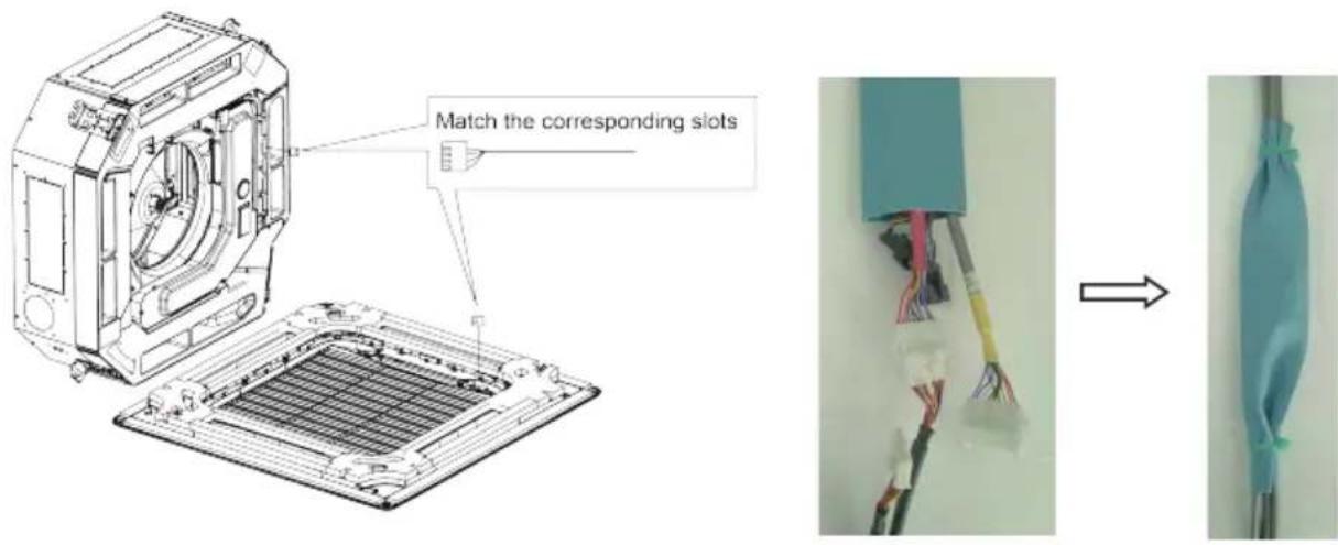

WARNING!
After installing the panel, the insulated protective cover with the thickness of 1mm shall be used to wrap the wiring terminal, Tighten the insulated glue cover on both sides with bonding tie to fix it.
5.6 Electrical Wiring
5.6.1 Wiring Precautions
 WARNING! WARNING! | |
| 1. Before obtaining access to terminals, all supply circuits must be disconnected. | |
| 2. The rated voltage of the unit is as shown as Table 4 | |
| 3. Before turning on, verify that the voltage is within the 198~264V range(for single phrase unit) or 342~457V range (for three-phrase unit). | |
| 4. Always use a special branch circuit and install a special receptacle to supply power to the air conditioner. | |
| 5. The special branch circuit breaker is installed in the permanent wiring. Always use a circuit that can trip all the poles of the wiring and has an isolation distance of at least 3mm between the contacts of each pole. | |
| 6. Perform wiring work in accordance with standards so that the air conditioner can be operated safely and positively. | |
| 7. Install a leakage special branch circuit breaker in accordance with the related laws and regulations and electric company standards. | |
WARNING!
CAUTION!
① The power source capacity must be the sum of the air conditioner current and the current of other electrical appliances. When the current contracted capacity is insufficient, change the contracted capacity.
② When the voltage is low and the air conditioner is difficult to start, contact the power company to raise the voltage.
5.6.2 Electrical Wiring
(1). For solid core wiring (Fig.36)
1). Cut the wire end with a wire cutter or wire-cutting pliers, then strip the insulation about 25 mm (15/16").
2). Using a screwdriver, remove the terminal screw(s) on the terminal board.
3). Using pliers, bend the solid wire to form a loop suitable for the terminal screw.
4). Shape the loop wire properly, place it on the terminal board and tighten securely with the terminal screw using a screwdriver.
(2). For strand wiring (Fig.36)
1). Cut the wire end with a wire cutter or wire-cutting pliers, then strip the insulation about 10 mm (3/8").
2). Using a screwdriver, remove the terminal screw (s) on the terminal board.
3). Using a round terminal fastener or pliers, securely clamp a round terminal to each stripped wire end.
4). Position the round terminal wire, and replace and tighten the terminal screw with a screwdriver.(Fig.37)
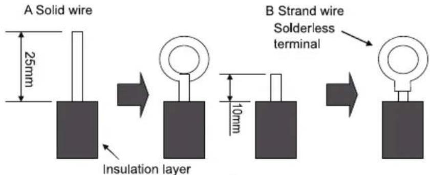
Fig.36
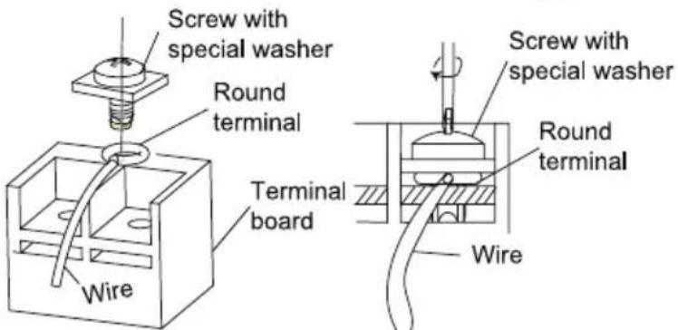
Fig.37

Fig.38
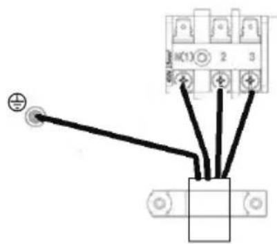
(3). How to fix connection cord and power cord by cord clamp
After passing the connection cord fasten it with the cord clamp.(Fig.38)
| WARNING! |
| 1. Before starting work, check that power is not being supplied to the indoor unit and outdoor unit. |
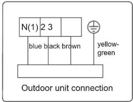
| 2. Match the terminal block numbers and connection cord colors with those of the indoor unit side.3. Erroneous wiring may cause burning of the electric parts. |
| 4. Connect the connection cords firmly to the terminal block. Imperfect installation may cause a fire. |
| 5. Always fasten the outside covering of the connection cord with cord clamps. (If the insulator is not clamped, electric leakage may occur.) |
| 6. Always connect the ground wire. |
(4). Electric wiring of indoor unit side
Take off the electric box cover from the sub-assembly of electric box. Then connect the wires. Connect the connection wires of indoor unit according to the corresponding marks.
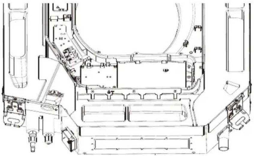
natural_image
Technical line drawing of a mechanical assembly with no visible text or symbols| CAUTION! |
| 1 Tighten the power cord respectively on the terminal boards with screws. Faulty connection may cause a fire. |
| 2 If the power supply are wired incorrectly, the air conditioner may be damaged. |
| 3 Connect the indoor unit connection cord properly based on the corresponding marks as shown in Fig.39. |
| 4 Ground both the indoor and outdoor units by attaching a ground wire. |
| 5 Unit shall be grounded in compliance with the applicable local and national codes. |
6 Installation of Controller
Refer to the Installation Manual of the controller for more details.
7 Test Running
7.1 Trial Operation and Testing
(1). The meaning of error codes as shown below:
Table 8
| Number Error code Error | ||
| 1 E1 Compressor high pressure protection | ||
| 2 E2 Indoor anti-freeze protection | ||
| 3 E3 | Compressor low pressure protection, refrigerant lack protection and refrigerant colleting mode | |
| 4 E4 | Compressor high discharge temperature protection | |
| 5 | E5 | AC over-current protection |
| 6 E6 Communication error | ||
| 7 | E7 | Mode conflict |
| 8 | E8 | Anti-high temperature protection |
| 9 E9 Full water protection | ||
| 10 | F1 | Indoor ambient temperature sensor is open/short circuited |
| 11 | F2 | Indoor evaporator temperature sensor is open/short circuited |
| 12 F3 Outdoor ambient temperature sensor is open/short circuited | ||
| 13 | F4 | Outdoor condenser temperature sensor is open/short circuited |
| 14 F5 | Outdoor discharge temperature sensor is open/short circuited | |
| 15 C5 | Jumper cap malfunction protection | |
| 16 | EE | Loading EEPROM malfunction |
Note: If there're other error codes, please contact qualified professionals for service.
When the unit is connected with the wired controller, the error code will be simultaneously shown on it.
(2). Instructions to the Error Indicating Lamps on the Panel of the Cassette Type Unit.
12\~18K:
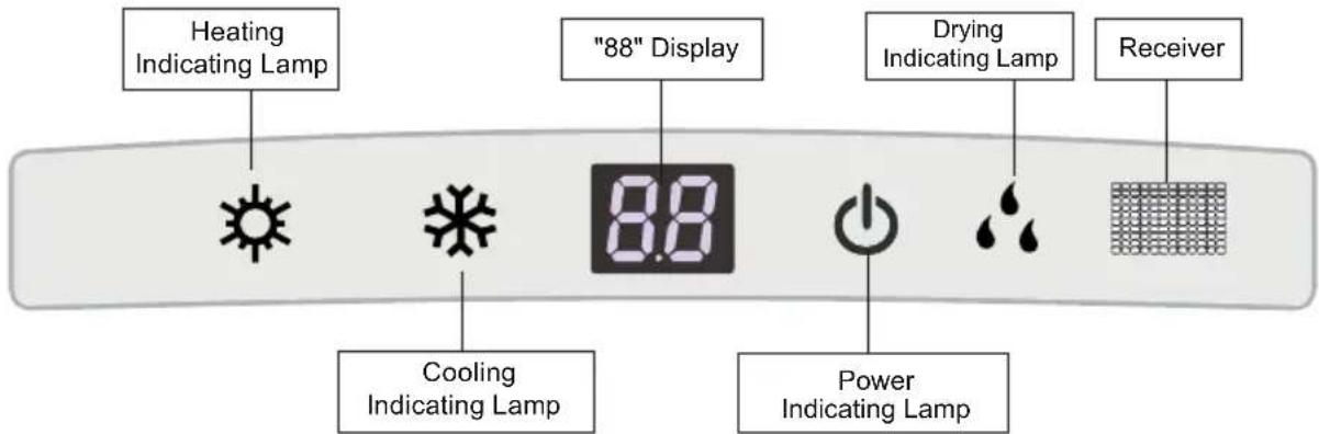
24K:
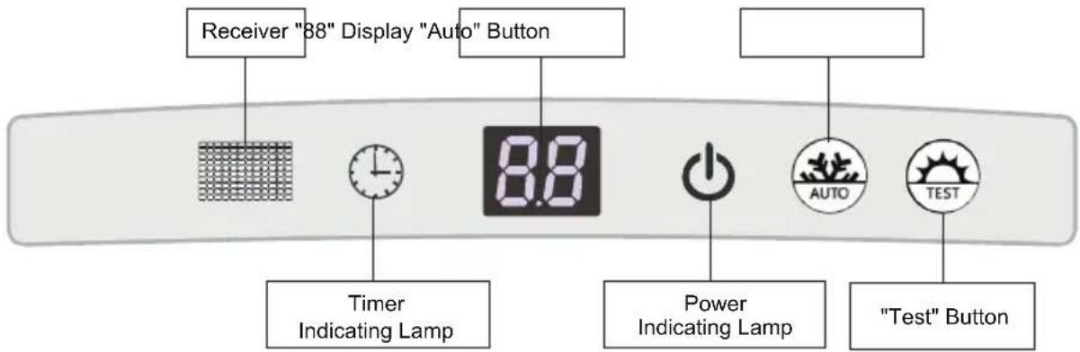
Fig.40
◆ Heating Indicating Lamp:
When this indicator is on, it indicates the heating mode is turned on.
◆ Cooling Indicating Lamp:
When this indicator is on, it indicates the cooling mode is turned on.
◆ Drying Indicating Lamp
When this indicator is on, it indicates the dry mode is turned on.
◆ Power and ON/OFF Indicating Lamp:
It goes red when the unit is powered on while it goes white when the unit is started.
◆ Timer Indicating Lamp:
Timer indicator on indoor unit will be on when timer ON is set under off status and timer OFF is set under on status.
◆ "88" Display:
When there is no error, the dual-8 nixie tube display the set temperature. After receiving the command of displaying indoor ambient temperature from the remote controller, the dual-8 nixie tube displays indoor temperature for 3s and then resume to display the set temperature. If there is error, error code will be displayed. If there's multiple error, error codes will be displayed in turn.
"Auto" button: It's used for turning on or turning off the unit. When use this button to turn in the unit, the unit is under auto mode.
"Test" button: It's only used for the test units. This button is only valid within 3mins after the unit is energized.
NOTE:
(1) If the light of indoor unit is turned off, when operating the remote controller to send command, the display will be on for 3s and then off.
(2) When the wired controller is connected, the indoor unit display is invalid and the unit won't receive the remote control command.
8 Troubleshooting and Maintenance
8.1 Troubleshooting
If your air-conditioning unit suffers from abnormal operation or failure, please first check the following points before repair:
Table 10
| Failure Possible | Reasons |
| The unit cannot be started. | 1. The power supply is not connected.2. Electrical leakage of air-conditioning unit causes tripping of the leakage switch.3. The operating keys are locked.4. The control loop has failure. |
| The unit operates for a while and then stops. | 1. There is obstacle in front of the condenser.2. The control loop is abnormal.3. Cooling operation is selected when the outdoor ambient temperature is above 48°C. |
| Poor cooling effect. | 1. The air filter is dirty or blocked.2. There is heat source or too many people inside the room.3. The door or window is open.4. There is obstacle at the air intake or outlet.5. The set temperature is too high.6 There is refrigerant leakage.7. The performance of room temperature sensor becomes worse |
| Poor heating effect | 1. The air filter is dirty or blocked.2. The door or window is not firmly closed.3. The set room temperature is too low.4. .egakael tnaregirfer si erħh5. The outdoor ambient temperature is lower than -5°C.6 Control loop is abnormal. |
Note: After carrying out the check of the above items and taking relevant measures to solve the problems but the air-conditioning unit still does not function well, please stop the operation of the unit immediately and contact the local service agency designated. Only ask professional serviceman to check and repair the unit.
8.2 Routine Maintenance
Only a qualified service person is allowed to perform maintenance
Before accessing to terminal devices, all power supply circuits must be disconnected.
Do not use water or air of 50^ C or higher for cleaning air filters and outside panels
Notes:
①. Do not operate the air conditioner with the filter uninstalled, otherwise dust would come into the unit.
②. Do not remove the air filter except for cleaning. Unnecessary handling may damage the filt.
③. Do not clean the unit with gasolene, benzene, thinner, polishing powder or liquid insecticide, otherwise it would cause discoloration and deformation of the unit.
④ Do not wet the indoor unit in case of electric shock or fire hazard
Increase the frequency of cleaning if the unit is installed in a room where the air is extremely contaminated.(As a yardstick for yourself, consider cleaning the filter once a half yea.)
If dirt becomes impossible to clean, change the air filter.
8.2.1 Clean Air Filter
If the air conditioner is used at a dusty place, clean the air filter regularly. (Once every half a year)
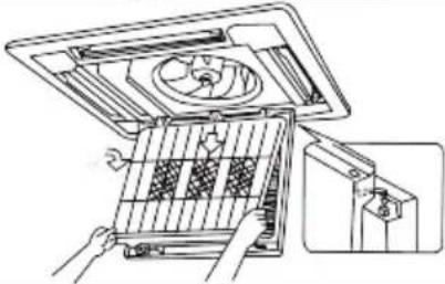
| How to clean the air filter | |
| (1) Open the air intake grill.Push the clasps outward and then open the air intake grill. | — |
| (2) Remove the air filter.1) Remove the screws by a screwdriver as shown in the picture.2) Push those two fasteners and open the panel grille.3) Open the air inlet grille at 45°, raise it and remove the grille.4) Disassemble the filter screenDraw out the filter screen and remove it. | 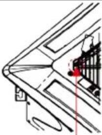 Remove the screw Remove the screw |
Push the fastener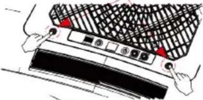 | |
 | |
| (3) Disassemble the air purifierRemove the air purifier after removing the fixed screws on it. | 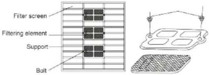 |
| (4) Cleaning the filer screenUse vacuum cleaner to remove dust or rinse the filter.If the filter is very dirty (greasy), use warm water (below 45°C) with neutral detergent to clean it. Then dry the filter at a cool place.NOTICE:do not use hot water (above 45°C) to clean, otherwise the filter may be discolored or out of shape. Do not dry it with fire, otherwise the filter will catch fire or become out of shape. | 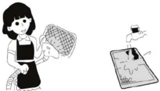 |
| (5) Fix the 3 cleaners on the filter and then re-install the filter by fitting it into the protruding parts on top of the air intake grill. Pull the handle at the back of the air intake grill to secure the filter. | — |
| (6) Close the air intake grill.Push the clasps outward and then match the air intake grill with the main body. Loose the clasps and then close it. | — |
9 Safety operation of flammable refrigerant
Qualification requirement for installation and maintenance man
- All the work men who are engaging in the refrigeration system should bear the valid certification awarded by the authoritative organization and the qualification for dealing with the refrigeration system recognized by this industry. If it needs other technician to maintain and repair the appliance, they should be supervised by the person who bears the qualification for using the flammable refrigerant.
- It can only be repaired by the method suggested by the equipment's manufacturer.
Installation notes
- The air conditioner is not allowed to use in a room that has running fire (such as fire source, working coal gas ware, operating heater).
- It is not allowed to drill hole or burn the connection pipe.
- The air conditioner must be installed in a room that is larger than the minimum room area. The minimum room area is shown on the nameplate or following table a.
- Leak test is a must after installation.
table a - Minimum room area ( m^2 )
| Minimum room area( m^2 ) | Charge amount (kg) | ≤1.2 | 1.3 | 1.4 | 1.5 | 1.6 | 1.7 | 1.8 | 1.9 | 2 | 2.1 | 2.2 | 2.3 | 2.4 | 2.5 | ||||
| floor location | / | 14.5 | 16.8 | 19.3 | 22 | 24.8 | 27.8 | 31 | 34.3 | 37.8 | 41.5 | 45.4 | 49.4 | 53.6 | |||||
| window mounted | / | 5.2 | 6.1 | 7 | 7.9 | 8.9 | 10 | 11.2 | 12.4 | 13.6 | 15 | 16.3 | 17.8 | 19.3 | |||||
| wall mounted | / | 1.6 | 1.9 | 2.1 | 2.4 | 2.8 | 3.1 | 3.4 | 3.8 | 4.2 | 4.6 | 5 | 5.5 | 6 | |||||
| ceiling mounted | / | 1.1 | 1.3 | 1.4 | 1.6 | 1.8 | 2.1 | 2.3 | 2.6 | 2.8 | 3.1 | 3.4 | 3.7 | 4 | |||||
Maintenance notes
- Check whether the maintenance area or the room area meet the requirement of the nameplate.
- It's only allowed to be operated in the rooms that meet the requirement of the nameplate.
- Check whether the maintenance area is well-ventilated.
- The continuous ventilation status should be kept during the operation process.
- Check whether there is fire source or potential fire source in the maintenance area.
- The naked flame is prohibited in the maintenance area; and the “no smoking” warning board should be hanged.
- Check whether the appliance mark is in good condition.
- Replace the vague or damaged warning mark.
Welding
- If you should cut or weld the refrigerant system pipes in the process of maintaining, please follow the steps as below:
a. Shut down the unit and cut power supply
b. Eliminate the refrigerant
c. Vacuuming
d. Clean it with N2 gas
e. Cutting or welding
f. Carry back to the service spot for welding
- The refrigerant should be recycled into the specialized storage tank.
- Make sure that there isn't any naked flame near the outlet of the vacuum pump and it's well-ventilated.
Filling the refrigerant
- Use the refrigerant filling appliances specialized for R32. Make sure that different kinds of refrigerant won't contaminate with each other.
- The refrigerant tank should be kept upright at the time of filling refrigerant.
- Stick the label on the system after filling is finished (or haven't finished).
- Don't overfilling.
- After filling is finished, please do the leakage detection before test running; another time of leak detection should be done when it's removed.
Safety instructions for transportation and storage
- Please use the flammable gas detector to check before unload and open the container.
- No fire source and smoking.
- According to the local rules and laws.
10. Specialist's Manual
- The following checks shall be applied to installations using flammable refrigerants:
– the charge size is in accordance with the room size within which the refrigerant containing parts are installed;
– the ventilation machinery and outlets are operating adequately and are not obstructed;
- if an indirect refrigerating circuit is being used, the secondary circuit shall be checked for the presence of refrigerant;
– marking to the equipment continues to be visible and legible. Markings and signs that are illegible shall be corrected;
– refrigeration pipe or components are installed in a position where they are unlikely to be exposed to any substance which may corrode refrigerant containing components, unless the components are constructed of materials which are inherently resistant to being corroded or are suitably protected against being so corroded.
- Repair and maintenance to electrical components shall include initial safety checks and component inspection procedures. If a fault exists that could compromise safety, then no electrical supply shall be connected to the circuit until it is satisfactorily dealt with. If the fault cannot be corrected immediately but it is necessary to continue operation, an adequate temporary solution shall be used. This shall be reported to the owner of the equipment so all parties are advised.
- Initial safety checks shall include:
– that capacitors are discharged: this shall be done in a safe manner to avoid possibility of sparking;
– that no live electrical components and wiring are exposed while charging, recovering or purging the system;
– that there is continuity of earth bonding.
- Checking for presence of refrigerant
The area shall be checked with an appropriate refrigerant detector prior to and during work, to ensure the technician is aware of potentially toxic or flammable atmospheres. Ensure that the leak detection equipment being used is suitable for use with all applicable refrigerants, i.e. non-sparking, adequately sealed or intrinsically safe.
• Presence of fire extinguisher
If any hot work is to be conducted on the refrigeration equipment or any associated parts, appropriate fire extinguishing equipment shall be available to hand. Have a dry powder or CO_2 fire extinguisher adjacent to the charging area.
- Ventilated area
Ensure that the area is in the open or that it is adequately ventilated before breaking into the system or conducting any hot work. A degree of ventilation shall continue during the period that the work is carried out. The ventilation should safely disperse any released refrigerant and preferably expel it externally into the atmosphere.
- Leak detection methods
Leak detection fluids are suitable for use with most refrigerants but the use of detergents containing chlorine shall be avoided as the chlorine may react with the refrigerant and corrode the copper pipe-work.
- Checks to the refrigeration equipment
Where electrical components are being changed, they shall be fit for the purpose and to the correct specification. At all times the manufacturer's maintenance and service guidelines shall be followed. If in doubt, consult the manufacturer's technical department for assistance.
- Checks to electrical devices
– that capacitors are discharged: this shall be done in a safe manner to avoid possibility of sparking;
– that no live electrical components and wiring are exposed while charging, recovering or purging the system.
• Repairs to sealed components
During repairs to sealed components, all electrical supplies shall be disconnected from the equipment being worked upon prior to any removal of sealed covers, etc. If it is absolutely necessary to have an electrical supply to equipment during servicing, then a permanently operating form of leak detection shall be located at the most critical point to warn of a potentially hazardous situation.
Particular attention shall be paid to the following to ensure that by working on electrical components, the casing is not altered in such a way that the level of protection is affected. This shall include damage to cables, excessive number of connections, terminals not made to original specification, damage to seals, incorrect fitting of glands, etc.
– Ensure that the apparatus is mounted securely.
- Ensure that seals or sealing materials have not degraded to the point that they no longer serve the purpose of preventing the ingress of flammable atmospheres. Replacement parts shall be in accordance with the manufacturer's specifications.
NOTE: The use of silicon sealant can inhibit the effectiveness of some types of leak detection equipment. Intrinsically safe components do not have to be isolated prior to working on them.
- Repair to intrinsically safe components
Do not apply any permanent inductive or capacitance loads to the circuit without ensuring that this will not exceed the permissible voltage and current permitted for the equipment in use.
Intrinsically safe components are the only types that can be worked on while live in the presence of a flammable atmosphere. The test apparatus shall be at the correct rating.
Replace components only with parts specified by the manufacturer. Other parts may result in the ignition of refrigerant in the atmosphere from a leak.
- Cabling
Check that cabling will not be subject to wear, corrosion, excessive pressure, vibration, sharp edges or any other adverse environmental effects. The check shall also take into account the effects of aging or continual vibration from sources such as compressors or fans.
• Detection of flammable refrigerants
Under no circumstances shall potential sources of ignition be used in the searching for or detection of refrigerant leaks. A halide torch (or any other detector using a naked flame) shall not be used.
- Decommissioning
Before carrying out this procedure, it is essential that the technician is completely familiar with the equipment and all its detail. It is recommended good practice that all refrigerants are recovered safely. Prior to the task being carried out, an oil and refrigerant sample shall be taken in case analysis is required prior to re-use of reclaimed refrigerant. It is essential that electrical power is available before the task is commenced.
a) Become familiar with the equipment and its operation.
b) Isolate system electrically.
c) Before attempting the procedure, ensure that:
- mechanical handling equipment is available, if required, for handling refrigerant cylinders;
– all personal protective equipment is available and being used correctly;
– the recovery process is supervised at all times by a competent person;
– recovery equipment and cylinders conform to the appropriate standards.
d) Pump down refrigerant system, if possible.
e) If a vacuum is not possible, make a manifold so that refrigerant can be removed from various parts of the system.
f) Make sure that cylinder is situated on the scales before recovery takes place.
g) Start the recovery machine and operate in accordance with manufacturer's instructions.
h) Do not overfill cylinders. (No more than 80% volume liquid charge).
i) Do not exceed the maximum working pressure of the cylinder, even temporarily.
j) When the cylinders have been filled correctly and the process completed, make sure that the cylinders and the equipment are removed from site promptly and all isolation valves on the equipment are closed off.
k) Recovered refrigerant shall not be charged into another refrigeration system unless it has been cleaned and checked.
- Labelling
Equipment shall be labelled stating that it has been de-commissioned and emptied of refrigerant. The label shall be dated and signed. For appliances containing flammable refrigerants, ensure that there are labels on the equipment stating the equipment contains flammable refrigerant.
- Recovery
When removing refrigerant from a system, either for servicing or decommissioning, it is recommended good practice that all refrigerants are removed safely. When transferring refrigerant into cylinders, ensure that only appropriate refrigerant recovery cylinders are employed. Ensure that the correct number of cylinders for holding the total system charge are available. All cylinders to be used are designated for the recovered refrigerant and labelled for that refrigerant (i.e. special cylinders for the recovery of refrigerant). Cylinders shall be complete with pressure-re-lief valve and associated shut-off valves in good working order. Empty recovery cylinders are evacuated and, if possible, cooled before recovery occurs.
The recovery equipment shall be in good working order with a set of instructions concerning the equipment that is at hand and shall be suitable for the recovery of all appropriate refrigerants including, when applicable, flammable refrigerants. In addition, a set of calibrated weighing scales shall be available and in good working order. Hoses shall be complete with leak-free disconnect couplings and in good condition. Before using the recovery machine, check that it is in satisfactory working
order, has been properly maintained and that any associated electrical components are sealed to prevent ignition in the event of a refrigerant release. Consult manufacturer if in doubt.
The recovered refrigerant shall be returned to the refrigerant supplier in the correct recovery cylinder, and the relevant waste transfer note arranged. Do not mix refrigerants in recovery units and especially not in cylinders.
If compressors or compressor oils are to be removed, ensure that they have been evacuated to an acceptable level to make certain that flammable refrigerant does not remain within the lubricant. The evacuation process shall be carried out prior to re-turning the compressor to the suppliers. Only electric heating to the compressor body shall be employed to accelerate this process. When oil is drained from a system, it shall be carried out safely.
deitsu
EUROFRED
being efficient
Eurofred S.A.