
DCB14 - Air conditioner DIMPLEX - Free user manual and instructions
Find the device manual for free DCB14 DIMPLEX in PDF.


| Product Type | Window/Wall Box Air Conditioner |
| Model | DCB14 |
| Power Supply | 220-240V~, 50Hz |
| Cooling Capacity | 4200W |
| Heating Capacity | 3600W |
| Moisture Removal | 1.7 L/h |
| Cooling Rated Power Input | 1280W |
| Heating Rated Power Input | 1070W |
| Cooling Rated Current | 5.7A |
| Heating Rated Current | 4.9A |
| Indoor Air Volume | 700 m³/h |
| Indoor Noise Level | 58 dB(A) |
| Outdoor Noise Level | 64 dB(A) |
| Refrigerant | R32 (660g) |
| Operating Temperature Range | 16-31°C |
| Ambient Temperature (Cooling) | 18-43°C |
| Ambient Temperature (Heating) | -7-27°C |
| Recommended Room Area | 20-30 m² |
| Dimensions (W x H x D) | 660 x 430 x 680 mm |
| Net Weight | 50 kg |
| Modes | Cool, Heat, Fan Only, Sleep |
| Special Functions | Timer, Auto Swing, Super, Eco |
| Warranty | Refer to warranty card in box |
Frequently Asked Questions - DCB14 DIMPLEX
User questions about DCB14 DIMPLEX
0 question about this device. Answer the ones you know or ask your own.
Ask a new question about this device
Download the instructions for your Air conditioner in PDF format for free! Find your manual DCB14 - DIMPLEX and take your electronic device back in hand. On this page are published all the documents necessary for the use of your device. DCB14 by DIMPLEX.
USER MANUAL DCB14 DIMPLEX
natural_image
Line drawing of a front-mounted air conditioner unit with ventilation grilles and fan slots (no text or symbols)Window/Wall Box Air Conditioner
Cooling Only: DCB05C
Reverse Cycle: DCB09 & DCB14
For domestic household use only.
CAUTION: FAILURE TO FOLLOW THESE INSTRUCTIONS MAY CAUSE INJURY AND/OR DAMAGE AND MAY INVALIDATE YOUR WARRANTY
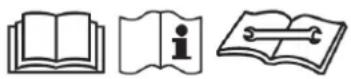
Please read the operating instructions carefully before using your Air Conditioner for the first time and keep them in a safe place.
WARNING - This appliance must not be used in a bathroom.
WARNING - Do not use this appliance in the immediate surroundings of a bath, a shower or a swimming pool.
- If the mains lead is damaged it must only be replaced by the manufacturers service agent or a similarly qualified person in order to avoid a hazard.
- This appliance is not intended for use by persons (including children) with reduced physical, sensory or mental capabilities, or lack of experience and knowledge, unless they have been given supervision or instruction concerning use of the appliance by a person responsible for their safety.
• Children should be supervised to ensure they do not play with the appliance. - Prior to cleaning or other maintenance, the appliance must be disconnected from the supply mains.
- Never immerse the appliance in water or other liquids.
- Operate this unit only on a firm, flat surface to avoid the risk of water leakage. Ensure that the unit is kept upright at all times.
- Do not place on soft, unstable or non-horizontal/angled surfaces.
- Never operate the appliance if a cable or connector has been damaged, after appliance malfunction or if the appliance was dropped or is otherwise damaged.
- Please ask a professional service agent to repair the product. Improper repair may cause danger to users.
- Disconnect the appliance from mains power whenever it is not in use, before relocating it, and before cleaning.
- Operate the appliance only at the voltage specified on the rating label.
- Only connect the unit to a properly installed and easily accessible socket so that you can quickly disconnect the plug if necessary.
- Do not connect this product to the mains using an extension lead.
- This product is only intended for INDOOR RESIDENTIAL applications. This product should not be used for commercial or industrial or leisure applications or in small enclosed spaces.
- Never use the mains lead as a carrying strap or pulling lead.
- To avoid a fire or electrocution hazard, NEVER put the cord near heat registers, radiator, stoves or heaters.
- Only operate this appliance with a minimum of 50cm clearance all around i.e. away from walls, furniture and overhanging objects such as curtains or a shelf.
- WARNING: To avoid danger of suffocation please remove all packaging materials particularly
plastic and EPS and keep these away from vulnerable people, children and babies.
- NEVER drop or insert any object or fingers into any openings.
- Do not cover or obstruct the air inlet and outlets.
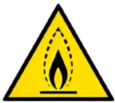
- Do not use the appliance in locations where paint, petrol or other flammable liquids are used or stored.
- Do not use bug sprays or other flammable cleansers/vapour sprays on or around the unit.
• Always switch off the unit and take the plug out of the socket:
• If you are not using the unit
- Before you clean or carry out maintenance on the unit
- If a fault occurs
• In the event of an electrical storm.
- Avoid electromagnetic interference. Keep the unit at least 1 metre away from electrical appliances such as televisions & radios.
- The air conditioner must always be stored and transported upright. In case of doubt we suggest you wait for at least 24 hours before operation. (Please keep unit upright at all times). The unit must be stored in a room without continuous operating sources (e.g. open flames, an operating gas appliance or an operating electric heater)
- This appliance shall be installed in accordance with national wiring regulations.
- DO NOT use differing processes to accelerate the defrosting process or to clean, other than what has been recommended by the manufacturer.
• Note that the refrigerant may be odourless.
• DO NOT operate this product with wet hands or in a damp environment. - DO NOT damage, use an unspecified power cord, modify power cord length or share the outlet with other appliances.
- DO NOT direct airflow at room occupants only. This also applies to pets and house-plants as it could be damaging to health.
- Disconnect the power if strange sounds, smell or some comes from the unit.
• Always install a circuit breaker and a dedicated power circuit.
• DO NOT open the unit during operation.
• DO NOT disassemble or modify the unit. - Ventilate the room before operating the air conditioner, if there is a gas leakage from another appliance.
- Ventilate the room well when unit is used together with another product such as a stove, as this may cause an oxygen shortage.
- DO NOT use this unit for special purposes, such as preservation of precision devices, food etc.
- This unit is not to be installed in caravans, motor homes etc.
- When the air filter is to be removed, do not touch the metal parts of the unit.
• DO NOT clean the air conditioner with water. NEVER drink water drained from unit. - Stop operation and close the window in the case of a storm.
- DO NOT hold the plug by the head of the power plug when taking it out, as this may cause electric shock.
- Turn off the main power switch when not using the device for an extended period of time.
- Never place obstacles around air-inlet or inside of air-outlet, as this could cause accidents.
- Ensure that the installation bracket of the appliance is not damaged.
• DO NOT place heavy objects on the power cord and ensure cord is not compressed. - If water enters the unit, turn the unit off and disconnect the power. Contact a qualified technician.

Exposed to the weather outdoors
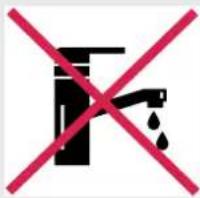
Near water If the power cable wires are frayed or cut
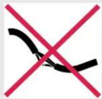
wires are frayed or cut

natural_image
Black silhouette of a person running with a crossed red diagonal line crossing through (no text or symbols)Where small children may be left unattended
No extensions leads or powerboards

Where the power cable may be damaged

natural_image
Symbol of a black box with two red X marks, no text or numbers presentOn a slope or uneven surface
Where there is risk of fire or close to a naked flame

Where it may be damaged by chemicals

Where there is a risk of interference by foreign objects

This product is not made for DIY repair

If there is a risk of water falling on the unit
Specifications
| Model no. DCB05C DCB09 DCB14 | ||||
| Power supply | 220-240V~, 50Hz | |||
| Cooling Capacity | 1700W | 2700W 4200W | ||
| Heating Capacity | / 2400W 3600W | |||
| Energy Star for Cooling | Cold 1.5 1.5 1.5 | |||
| Mixed 1.5 1.5 1.5 | ||||
| Hot/Humid 2.0 | 2.0 2.0 | |||
| Energy Star for Heating | Cold / 1.0 1.0 | |||
| Mixed | / 1.0 1.0 | |||
| Hot/Humid | / 1.0 1.0 | |||
| Moisture removal (L/h) | 0.6 | 1.0 1.7 | ||
| Cooling Rated Power Input | 520W | 820W 1280W | ||
| Heating Rated Power Input / | 690W | 1070W | ||
| Cooling Rated Current | 2.3A 3.6A | 5.7A | ||
| Heating Rated Current | / 3.0A | 4.9A | ||
| Indoor Air Volume | 420m^3/h | 430m^3/h | 700m^3/h | |
| Max. Pressure | Discharge | 4.5 | 4.3 | 4.3 |
| Suction | 1.5 | 1.2 1.2 | ||
| Inside Noise Level | 57dB(A) | 53dB(A) | 58dB(A) | |
| Outside Noise Level | 65dB(A) 63dB(A) | 64dB(A) | ||
| Refridgerant (g) | R32 (235g) | R32 (580g) | R32 (660g) | |
| Operating Temperature | 16-31°C | 16-31°C | 16-31°C | |
| Ambient temp (Cooling/Heating) | 18-43°C | 18-43°C/-7-27°C | 18-43°C/-7-27°C | |
| Application Area | 8-11m^2 | 10-18m^2 | 20-30m^2 | |
| Dimensions (W x H x D mm) | 470 x 355 x 535 | 600 x 380 x 560 | 660 x 430 x 680 | |
| Net Weight | 25kg | 35kg | 50kg | |
Parts
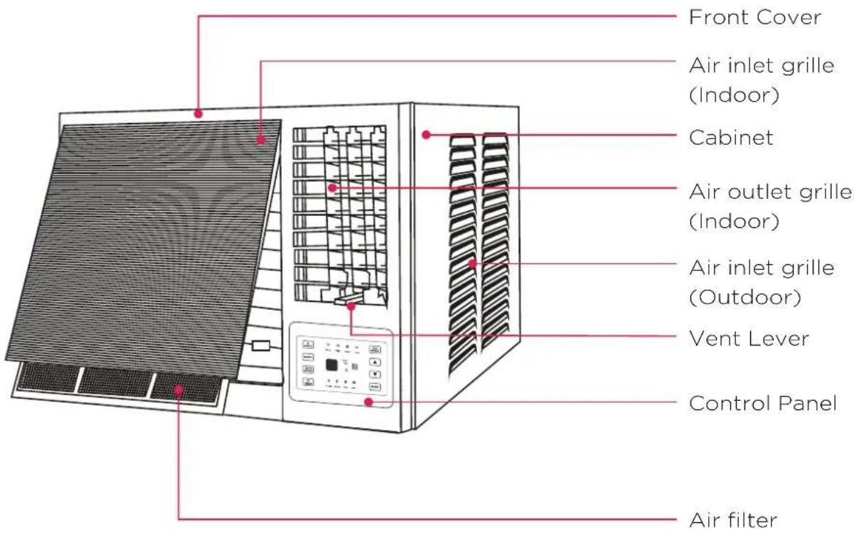
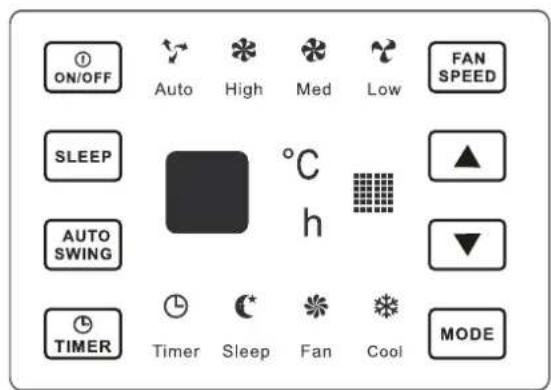
Control Panel
DCB05C
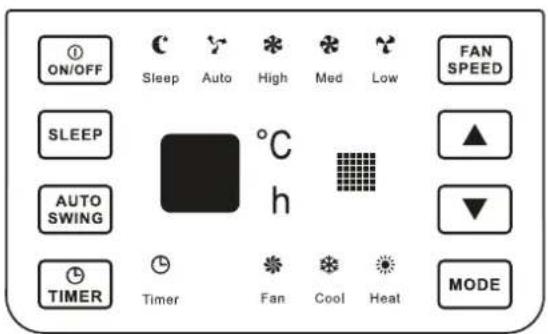
DCB09 DCB14
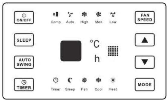
Operating Instructions - Control Panel
| Button Function | |
 | Used to adjust airflow direction |
 | Used to set or cancel timer operation.When the unit is in operation, you can set the OFF TIMER. When the unit is off, you can set ON TIMER. Timer setting range is 0 to 24 hours.If the OFF TIMER is set, the timer LED displays the remaining time to turn off the unit for only 10 seconds, then LED shifts to display set temperature.If you press TIMER button within 10 seconds, OFF TIMER will be cancelled.If the ON TIMER is set, the timer LED displays the remaining time to turn on the unit. If you want to cancel the ON TIMER, press the TIMER button. |
 | Everytime you press this button, the air conditioner will be started when it is energised or will be stopped when it is in operation. |
 | Everytime you press this button, the operation mode is changed in sequence: COOLING - FAN ONLY - HEATING - COOLING |
 | Used to select fan speed in sequence auto, low, mid and high. |
 | This button is used to set room temperature mode or used to set time in TIMER mode.NOTE: Temperature setting range is from 61 degrees farenheit (16 degrees celcius) to 88 degrees farenheit (31 degrees celcius) |
 | |
 | Used to activate the 'SLEEP' function. |
Operating Instructions - LED Indication Symbols
| Button Function | |
 | Timer |
 | Cooling |
 | Heating |
 | Fan Only |
 | Sleep |
 | Display Set Temp/Display Set Timer |
 | Low Fan Speed |
 | Mid Fan Speed |
 | High Fan Speed |
 | Auto Fan Speed |
 | Compressor Running |
Remote Control
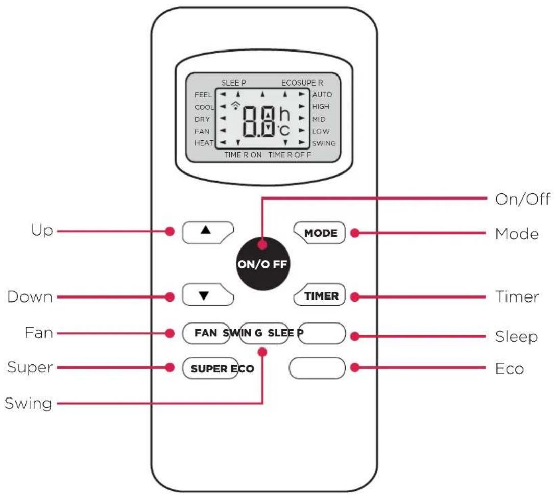
flowchart
graph TD
    A["ON/O FF"] --> B["MODE"]
    A --> C["TIMER"]
    A --> D["FAN SWIN G SLEEP"]
    A --> E["SUPER ECO"]
    A --> F["Super"]
    A --> G["Down"]
    A --> H["Up"]
    A --> I["Energy Control Interface"]
    style A fill:#f9f,stroke:#333
    style B fill:#ccf,stroke:#333
    style C fill:#ccf,stroke:#333
    style D fill:#ccf,stroke:#333
    style E fill:#ccf,stroke:#333
    style F fill:#ccf,stroke:#333
    style G fill:#ccf,stroke:#333
    style H fill:#ccf,stroke:#333
    style I fill:#ccf,stroke:#333
USING THE REMOTE CONTROL
- Open the battery cover of the remote control, and insert 2 x AAA batteries.
- Please point at the receiver and be within 8m when using the remote control.
- If the battery voltage is low, please open the battery cover as per the diagram and replace with new batteries (2 x AAA). Then replace the battery cover.
Operating Instructions - Remote Control
| Button Function | |
 | • Used to turn the unit on and off |
| [W7CS] | • Used to set room temperature mode or used to set time in TIMER mode. If the two keys are pressed at the same time for more than 3 seconds, the temperature LED display will alternate between celcius and farenheit. |
| [SZYI] | • NOTE: Temperature setting range is from 16 degrees celcius (61 degrees farenheit) to 31 degrees celcius (88 degrees farenheit) |
 | • Used to select fan speed in sequence auto, low, mid and high. |
 | • Used to set or cancel the timer function |
| [SX37] | • Used to select the 'Sleep' function |
 | • Everytime you press this button, the operation mode is changed in sequence: COOLING - FAN ONLY - HEATING - COOLING |
 | • Used to adjust airflow direction |
 | • Used to activate the 'Eco' function |
 | • Press this button to activate/deactivate the 'Super' function. This function enables the unit to reach the preset temperature in the shortest time |
Electrical Specifications
- All wiring must comply with local and national electrical codes and must be installed by a qualified electrician. If you have any questions regarding the following instructions, contact a qualified electrician.
- Check available power supply and resolve any wiring problems BEFORE installing and operating this unit.
- For your safety and protection, this unit must be grounded through the power cord when plugged into a matching wall outlet. If you are not sure whether your wall outlet is properly grounded, please contact a qualified electrician.
- The rating plate on the unit contains electrical and other technical data. The rating plate is located on the right side of the unit. Make sure to use the correct power supply according to the rating plate of your air conditioner.
- Wiring diagrams are located to the right.
Electric Shock Hazard
- The air conditioner has a serial rating volt. It must have its own fuse or circuit breaker, and no other device or unit should be operated on the fuse or circuit breaker.
• To avoid the possibility of personal injury, disconnect power to the unit before installing or servicing.
CAUTION
- If the supply cord is damaged, it must be replaced by the manufacturer, its service agent or similarly qualified persons in order to avoid a hazard.
DCB05C
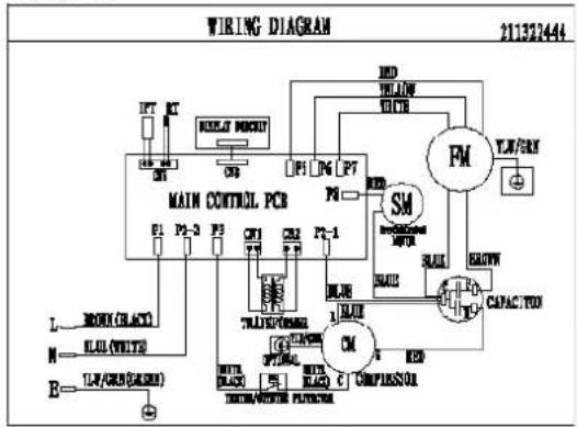
flowchart
graph TD
    A["MAIN CONTROL PCB"] --> B["Motor"]
    A --> C["Capacitor"]
    A --> D["Control Circuit"]
    B --> E["Power Supply"]
    C --> F["Power Supply"]
    D --> G["Power Supply"]
    E --> H["Ground"]
    F --> I["Ground"]
    G --> J["Ground"]
    H --> K["Control Circuit"]
    I --> K
    J --> K
    K --> L["Power Supply"]
    style A fill:#f9f,stroke:#333
    style B fill:#ccf,stroke:#333
    style C fill:#cfc,stroke:#333
    style D fill:#fcc,stroke:#333
DCB09
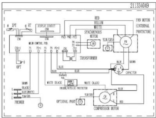
flowchart
graph TD
    A["OPT"] --> B["BLTR"]
    B --> C["BLTR"]
    C --> D["BLTR"]
    D --> E["BLTR"]
    E --> F["BLTR"]
    F --> G["BLTR"]
    G --> H["BLTR"]
    H --> I["BLTR"]
    I --> J["BLTR"]
    J --> K["BLTR"]
    K --> L["BLTR"]
    L --> M["BLTR"]
    M --> N["BLTR"]
    N --> O["BLTR"]
    O --> P["BLTR"]
    P --> Q["BLTR"]
    Q --> R["BLTR"]
    R --> S["BLTR"]
    S --> T["BLTR"]
    T --> U["BLTR"]
    U --> V["BLTR"]
    V --> W["BLTR"]
    W --> X["BLTR"]
    X --> Y["BLTR"]
    Y --> Z["BLTR"]
    Z --> AA["BLTR"]
    AA --> AB["BLTR"]
    AB --> AC["BLTR"]
    AC --> AD["BLTR"]
    AD --> AE["BLTR"]
    AE --> AF["BLTR"]
    AF --> AG["BLTR"]
    AG --> AH["BLTR"]
    AH --> AI["BLTR"]
    AI --> AJ["BLTR"]
    AJ --> AK["BLTR"]
    AK --> AL["BLTR"]
    AL --> AM["BLTR"]
    AM --> AN["BLTR"]
    AN --> AO["BLTR"]
    AO --> AP["BLTR"]
    AP --> AQ["BLTR"]
    AQ --> AR["BLTR"]
    AR --> AS["BLTR"]
    AS --> AT["BLTR"]
    AT --> AU["BLTR"]
    AU --> AV["BLTR"]
    AV --> AW["BLTR"]
    AW --> AX["BLTR"]
    AX --> AY["BLTR"]
DCB14
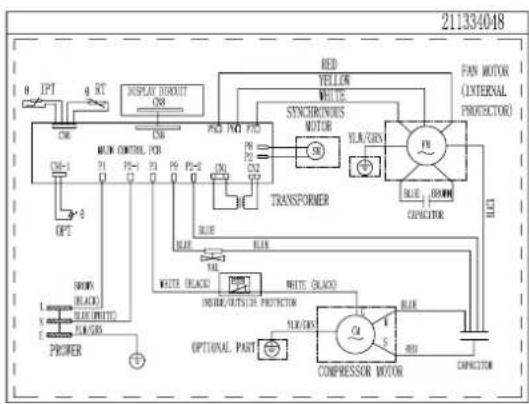
flowchart
graph TD
    A["POWER"] --> B["BLIN"]
    B --> C["BLUE BLIN"]
    C --> D["BLUE OFF/BLIN SWITCH"]
    D --> E["INTL/INTL SWITCH"]
    E --> F["COMPRESSOR MOTOR"]
    F --> G["CONCICUM"]
    G --> H["FAN MOTOR (INTERNAL PROTECTOR)"]
    H --> I["PAN MOTOR"]
    I --> J["FLA/GEN"]
    J --> K["TRANSFORMER"]
    K --> L["STANDARD SWITCH"]
    L --> M["INTERIOR SWITCH"]
    M --> N["OPEN SWITCH"]
    N --> O["OFF/INTL SWITCH"]
    O --> P["INTL/INTL SWITCH"]
    P --> Q["CONCICUM"]
    Q --> R["FAN MOTOR"]
    R --> S["PAN MOTOR (INTERNAL PROTECTOR)"]
    S --> T["PAN MOTOR"]
    T --> U["FAN MOTOR"]
    U --> V["FAN MOTOR"]
    V --> W["FAN MOTOR"]
    W --> X["FAN MOTOR"]
    X --> Y["FAN MOTOR"]
    Y --> Z["FAN MOTOR"]
| RECEPTACLE AND FUSE TYPES | |
| RATED VOLTS | 250 |
| AMPS | 3.15 |
REMOVE ALL THE SHIPPING PARTS BEFORE INSTALLATION
LOCATION
- Select a location that can support the weight of the air conditioner and one that will not cause increased operation noise and vibration.
- Direct sunlight is not favourable for efficient cooling.
- Select a place where there is limited obstacles near the air inlet and outlet.
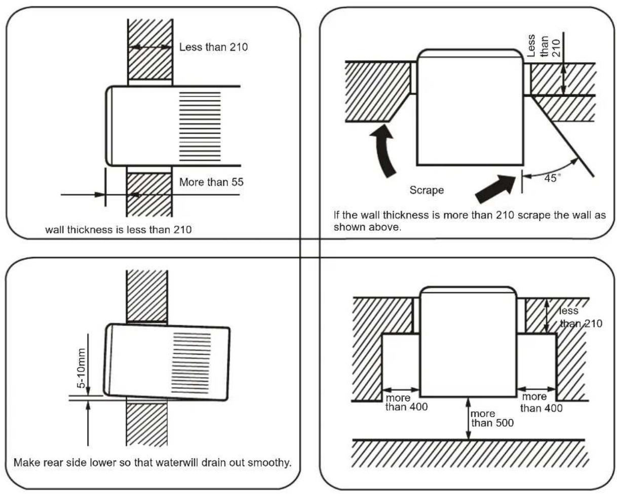
Installation
CAUTION
- Do not install air conditioner in a place where flammable gas leaks are a possibility.
- The minimum clearance from the appliance to combustible surfaces is 100mm; (Only for electric heating)
- The range of external static pressures at which the appliance was tested is 0-5Pa.
- Before installation, turn off the operation switch and disconnect the power cord.
- This appliance is not intended for use by individuals (including children) with reduced physical, sensory or mental capabilities, or a lack of experience or knowledge, unless there is supervision or instruction concerning use of the appliance from a person responsible for their safety.
- The appliance is fitted with means for disconnection. The supply mains have a contact separation in all poles that provide full disconnection for voltage category III conditions, and this means it must be incorporated in the fixed wiring in accordance with the wiring rules.
OPERATION
- Check the capacity of wiring and power outlet. The power outlet should be used exclusively for this air conditioner. Do not use it with other appliances.
- Ground the air conditioner to prevent the danger of electric shocks.
- Connect the air conditioner with its' power source securely.
- Use a fuse as above.
Installation
INSTALLATION INSTRUCTIONS
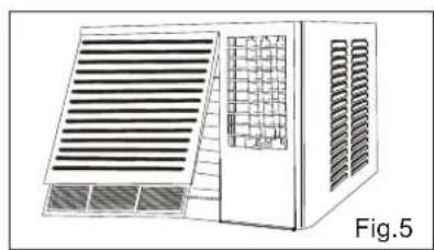
- Remove the front panel. (Fig.5)
- Remove the air filter. (Fig.6)
- Remove screws at the bottom of the front panel. (Fig.7)
- Open the panel cover.
- Remove the screws that fix the chassis-fixing board and cabinet. Some models have two more screws on the back of the cabinet. (Fig.8)
- Grasp the handle on the front of the chassis and carefully slide the air conditioner unit out of the cabinet. (Fig.9)
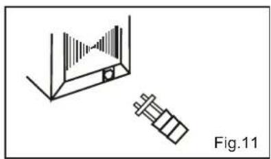
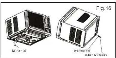
- Install the drain lube connection into the hole provided at the rear of the air conditioner chassis. (Fig.11) To meet different requirements of different types of air conditioner, there are two methods of choice to treat the condensed water: Bottom drainage or back drainage. For bottom drainage, the drain tray is fixed in position through four pcs of screws and use the flare nut to block the back drainage hole. (Fig.15) For Back drainage, use the flare nut to block the bottom drainage hole and use the water outlet pipe to connect the back drainage hole. Increase the sealing ring to prevent water leakage. (Fig.16)
- Install the air conditioner cabinet on the installation shelf (not included) with screws. (Fig.10)
- Carefully slide the unit back into the cabinet. (Fig.12)
- Reinstall the retaining bracket, front panel and mounting screws. (Fig.7,8,13)
- Reinstall the air filter. (Fig.14)
natural_image
Illustration of a modular air conditioner unit with ventilation grilles and heat sinks (no text or symbols)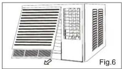
natural_image
Diagram of a modular air vent system with ventilation grilles and a grid-patterned chamber (no text or symbols)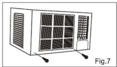
natural_image
Line drawing of a portable air conditioner unit with ventilation grilles and ventilation slots (no text or symbols)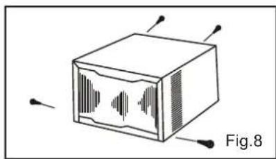
natural_image
Diagram of a device labeled Fig.8 showing a rectangular box with internal waveform patterns and four corner connectors (no text or symbols on the diagram itself)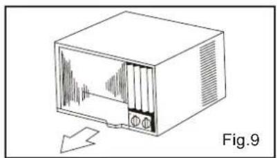
natural_image
Line drawing of a vintage television set with a CD and monitor, showing sound waves inside (no text or symbols)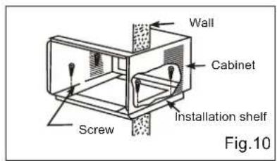
natural_image
Simple line drawing of a container with a side panel and a separate mechanical component, labeled Fig.11 (no text or symbols on the diagram itself)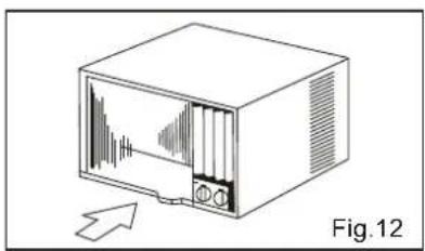
natural_image
Illustration of a vintage television set with an arrow pointing to it, labeled Fig.12 (no text or symbols on the device itself)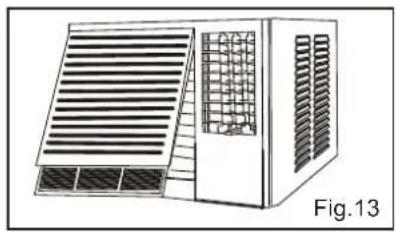
natural_image
Illustration of a modular air vent system with slatted panels and ventilation grilles (no text or symbols)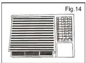
natural_image
Diagram of a ventilation system with horizontal slats and grid-patterned components (no text or symbols)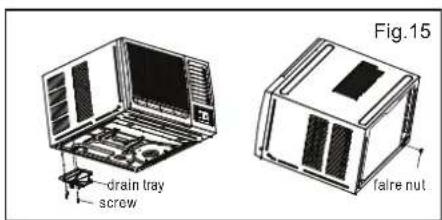
Care and Maintenance
AIR FILTER
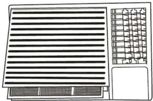
- The air filter should be washed at least once a month. If the air filter reamins full of dust, the air flow will decrease and the cooling capacity will be reduced.
• The filter is behind the cover and to be pulled out from the right hand side. - Wash the air filter with water and detergent.
- Rinse with clean water and dry completely before reinstalling.
natural_image
Technical line drawing of a ventilation grille and grid layout (no text or symbols)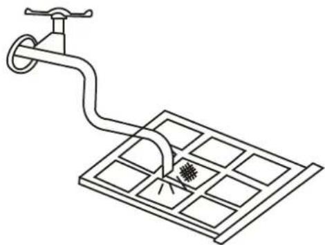
natural_image
Line drawing of a faucet with a drain and grid array, no text or symbols presentCAUTION
- Do not use hot water above 40 degrees celsius for washing the air filer.
- Let the filter dry thoroughly in the shade before reinstalling. Do not expose it directly to the sun
- Do not operate the air conditioner with the filter removed.
- The ambient temperature for cooling is 18-43 degrees celcius. The ambient temperature for heating is -5-20 degrees celcius.
AIR CLEANING FILTER
- The air cleaning filter is attached to the air filter. Wash the air cleaning filter as well when washing the air filter.
FRONT COVER
- The front cover will accumulate dirt and dust. To clean it, wipe it with a soft dry cloth. When it is excessively dirty, wipe it with a soft cloth dampened with warm water or mild soap, then wipe it again throughly with a soft dry cloth.
Storage Maintenance
Storage
If not using the unit for an extended period of time, after cleaning please:
- Turn the unit off, unplug and take care of the mains lead & plug.
- Drain the unit's water collection tray according to the instructions.
- Run the appliance on FAN mode for 12 hours in a warm room to dry it and prevent mould.
- Clean the air filter as described in the previous section.
- Remove batteries from the remote control.
- Cover the unit and store it upright in a location where it will not receive direct sunlight. Prolonged exposure to direct sunlight will discolour the enclosure.
If the unit fails to operate efficiently, is broken or other problems arise, unplug and do not operate. Ask for advice by calling your local after sales service agent or the Customer Care Centre on 1300 556 816 (AU) / 0800 666 2824 (NZ).
Warranty
Please refer to the warranty card in the box for warranty information. For any troubleshooting advice, please contact the relative Customer Care Centre below.
Glen Dimplex Australia Pty Ltd Glen Dimplex New Zealand Ltd
8 Lakeview Drive, 38 Harris Road, East Tamaki,
Scoresby 3179, Victoria Auckland 2013
Australia New Zealand
Ph: 1300 556 816 Ph: 0800 666 2824
natural_image
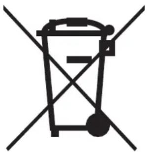
Symbol of a trash bin crossed with two diagonal lines, representing no waste or discharge (no text or labels)Recycling: Do not dispose of electrical appliances as unsorted municipal waste. Use separate collection facilities. Contact your local government for information regarding the collection systems available. If electrical appliances are disposed of in landfills or dumps, hazardous substances can leak into the ground water, polluting the food chain and damaging health and well-being.
Notes
DCDimplex®
Customer Care: 1300 556 816
customer.care@glendimplex.com.au
www.dimplex.com.au
Supplied by Glen Dimplex Australia
8 Lakeview Drive, Scoresby, Victoria, 3179
© Glen Dimplex Australia. All rights reserved. Material contained in this publication may not be reproduced in whole or in part, without prior permission in writing of Glen Dimplex Australia.
DCB R32 Rev 2
- Window/Wall Box Air Conditioner
- CAUTION: FAILURE TO FOLLOW THESE INSTRUCTIONS MAY CAUSE INJURY AND/OR DAMAGE AND MAY INVALIDATE YOUR WARRANTY
- Specifications
- Parts
- Control Panel
- Operating Instructions - Control Panel
- Operating Instructions - LED Indication Symbols
- Remote Control
- USING THE REMOTE CONTROL
- Operating Instructions - Remote Control
- Electrical Specifications
- Electric Shock Hazard
- CAUTION
- REMOVE ALL THE SHIPPING PARTS BEFORE INSTALLATION
- LOCATION
- Installation
- OPERATION
- INSTALLATION INSTRUCTIONS
- Care and Maintenance
- AIR FILTER
- AIR CLEANING FILTER
- FRONT COVER
- Storage Maintenance
- Storage
- Warranty
- Glen Dimplex Australia Pty Ltd Glen Dimplex New Zealand Ltd
- Notes
- DCDimplex®
Brand : DIMPLEX
Model : DCB14
Category : Air conditioner