
CAB15AR - Air conditioner DIMPLEX - Free user manual and instructions
Find the device manual for free CAB15AR DIMPLEX in PDF.


| Product Type | Ceiling Recessed Air Curtain (Ambient Model, Fan Only) |
| Brand | Dimplex |
| Model | CAB15AR |
| Dimensions (Length) | 1724 mm |
| Weight | 25 kg |
| Maximum Installation Height | 3.0 m |
| Electrical Supply | 220-240 V ~ 1 Ph+N |
| Electrical Load (per phase) | 0.5 A (fan only) |
| Heat Output | None (Ambient model) |
| Installation Type | Recessed into ceiling void or above suspended ceiling |
| Control Options | Switch box (CABC6 for ambient), door switch, BMS/BEMS |
| Fan Speed Settings | High, Low (via switch box) |
| Door Switch Compatibility | Yes (normally open switch) |
| BMS Compatibility | Yes (connections S0, S1, S2) |
| Safety Features | Thermal safety cut-outs, automatic run-on after door closure |
| Cleaning Interval (Internal) | At least every 3 months, more if needed |
| Cleaning Method | Vacuum with brush attachment after opening grille |
| Motor Lubrication | Not required (sealed bearings) |
| Warranty | 3 years from purchase |
| IP Rating (Not specified) | Indoor use only |
Frequently Asked Questions - CAB15AR DIMPLEX
User questions about CAB15AR DIMPLEX
0 question about this device. Answer the ones you know or ask your own.
Ask a new question about this device
Download the instructions for your Air conditioner in PDF format for free! Find your manual CAB15AR - DIMPLEX and take your electronic device back in hand. On this page are published all the documents necessary for the use of your device. CAB15AR by DIMPLEX.
USER MANUAL CAB15AR DIMPLEX
natural_image
3D rendering of a rectangular electronic device with three vertical posts and mounting base (no text or symbols visible)CABR
CAB10AR, CAB10ER, CAB10WR, CAB15AR, CAB15ER & CAB15WR
DABR
DAB10AR, DAB10ER, DAB10WR, DAB15AR, DAB15ER & DAB15WR
08/50590/0 (UK) Issue 8
1

natural_image
Pure technical line drawing of a rectangular plate with three circular holes, no text or symbols present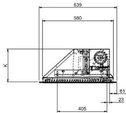
| A | B | C | D | E | F | G | H | J | K | L | |
| CAB10 E/A/W R 1 | 224 11 | 60 106 | 5 920 | 840 98 | 54 240 | 20 26 | 7 192 | ||||
| CAB15 E/A/W R 1 | 724 16 | 60 157 | 0 1420 | 1260 | 98 54 | 240 20 | 267 192 | ||||
| DAB10 E/A/W R 1 | 224 11 | 60 105 | 8 920 | 800 10 | 5 47 30 | 0 33 3 | 38 271 | ||||
| DAB15 E/A/W R 1 | 724 16 | 60 155 | 8 1420 | 1300 | 105 47 | 300 33 | 338 271 |
2A

natural_image
Technical line drawing of a mechanical device with no visible text or symbols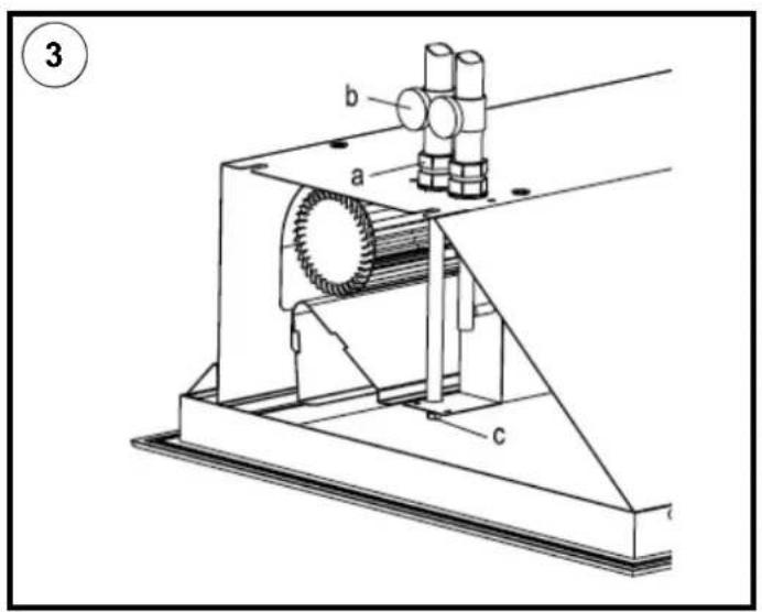

natural_image
3D rendering of a rectangular electronic component with three vertical wires and mounting base (no text or symbols visible)
natural_image
3D rendering of a rectangular structure with vertical supports and a sloped top, labeled '7B' in the top-left corner (no other text or symbols)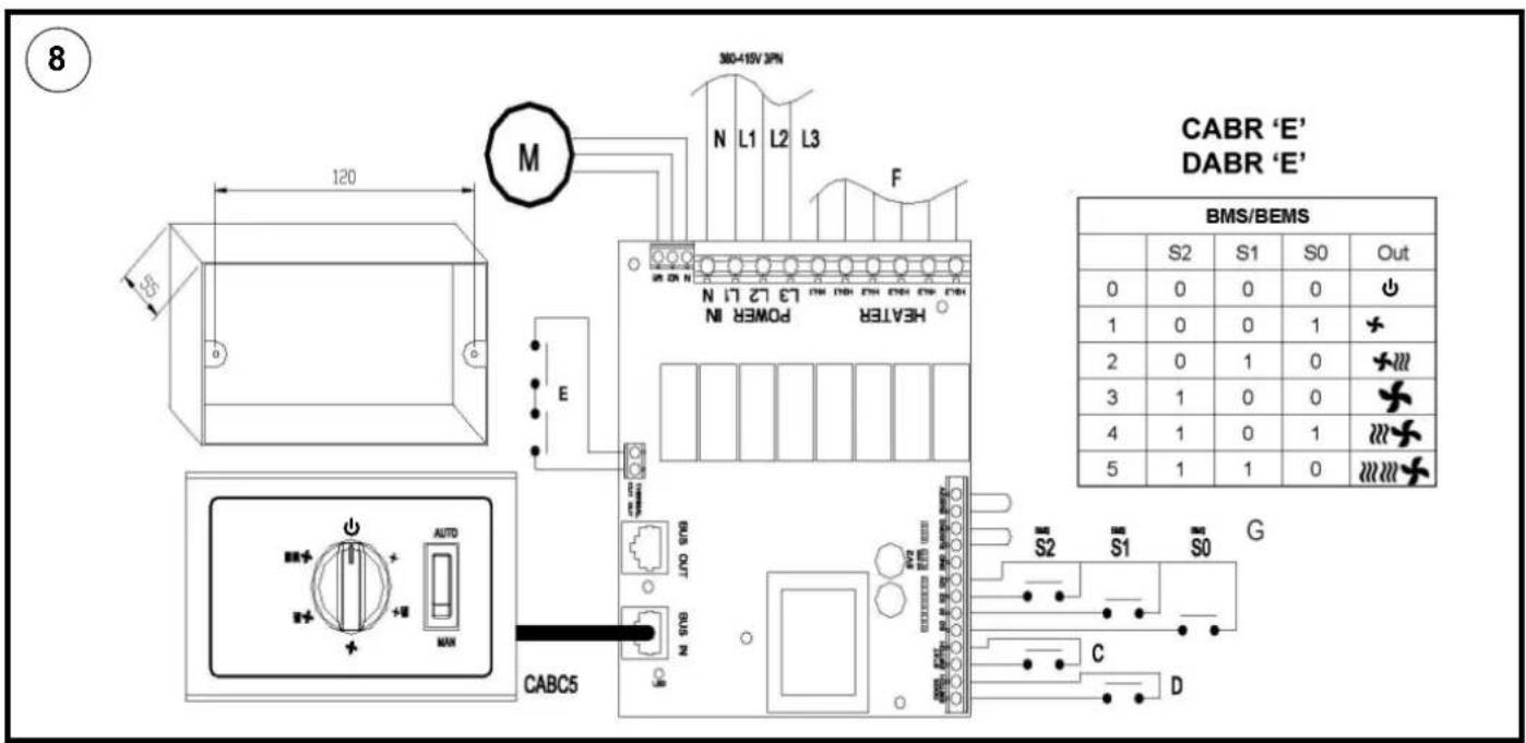

Important Safety Advice
DO NOT COVER OR OBSTRUCT the air inlet or outlet grille.
THIS APPLIANCE MUST BE EARTHED
IMPORTANT – Disconnect from the mains supply before carrying out maintenance work.
WARNING: Means for disconnection must be incorporated in the fixed wiring in accordance with the wiring rules.
WARNING: Always isolate the mains electrical supply before performing any work on these products.
WARNING: Where multiple units are installed ensure that the supply to each of the air curtains is isolated before any maintenance work begins. Any and all invasive work (inside of the air curtain's outer casing) on these products must be carried out by a suitably qualified, competent and approved electrician.
WARNING: Failure to adequately maintain the unit and provide a suitable cleaning schedule will result in a loss of performance, a reduction in the life expectancy of the air curtain and an increased risk of overheating and fire with electrically heated models.
DO NOT use this heater in areas where excessive dust exists.
This heater must not be located immediately above or below a fixed socket outlet or connection box.
DO NOT use this heater in the immediate surrounding of a bath, a shower or a swimming pool.
A suitable termination to the fixed wiring of the premises must be provided adjacent to the final position of the appliance.
DO NOT store or use any flammable materials or sprays in the vicinity of the appliance – FIRE HAZARD.
DO NOT insert any foreign objects into the appliance openings. Risk of injury, electric shock or damage to the appliance may occur.
Ensure the cables are in accordance with current IEE wiring regulations, are of adequate current carrying capacity and are protected by a suitable fuse. Cable size selection, to be selected in accordance with the maximum loading / demand of the product, and protected by a suitably rated overcurrent protection device.
The socket-outlet must be accessible at all times to enable the mains plug to be disconnected as quickly as possible.
The instruction leaflet belongs to the appliance and must be kept in a safe place.
If changing owners, the leafl et must be surrendered to the new owner.
This appliance is not intended for use by persons (including children) with reduced physical, sensory or mental capabilities, or lack of experience and knowledge, unless they have been given supervision or instruction concerning use of appliance by a person responsible for their safety.
This appliance can be used by children from 8 years and above and persons with reduced physical, sensory or mental capabilities or lack of experience and knowledge if they have been given supervision or instruction concerning use of the appliance. Children shall not play with the appliance. Cleaning and user maintenance shall not be made by children without supervision.
Children of less than 3 years should be kept away unless continuously supervised. Children aged from 3 years and less than 8 years shall only switch on/off the appliance provided that it has been placed or installed in its intended normal operating position and they have been given supervision or instruction concerning use of the appliance in a safe way and understand the hazards involved. Children aged from 3 years and less than 8 years shall not plug in, regulate and clean the appliance or perform user maintenance.
CAUTION — Some parts of this product can become very hot and cause burns. Particular attention has to be given where children and vulnerable people are present.
WARNING: This heater is not equipped with a device to control the room temperature.
Do not use this heater in small rooms when they are occupied by persons not capable of leaving the room, unless constant supervision is provided.
INSPECTION
The frequency of the cleaning schedule is dependent upon the environment the air curtain has been installed into. As a minimum Dimplex recommend a weekly inspection to ensure that there is no significant build-up of dust or dirt reducing the performance of the air curtain and causing nuisance smell. Upon inspection, if any foreign objects are encountered which may cause damage to the fan, impellors or elements they must be removed.
The external appearance of the air curtain can be maintained by wiping occasionally with a damp cloth. For stain removal, a weak soap solution can be applied with a cloth and the surface wiped dry. Care must be taken to avoid any moisture ingress into the product.
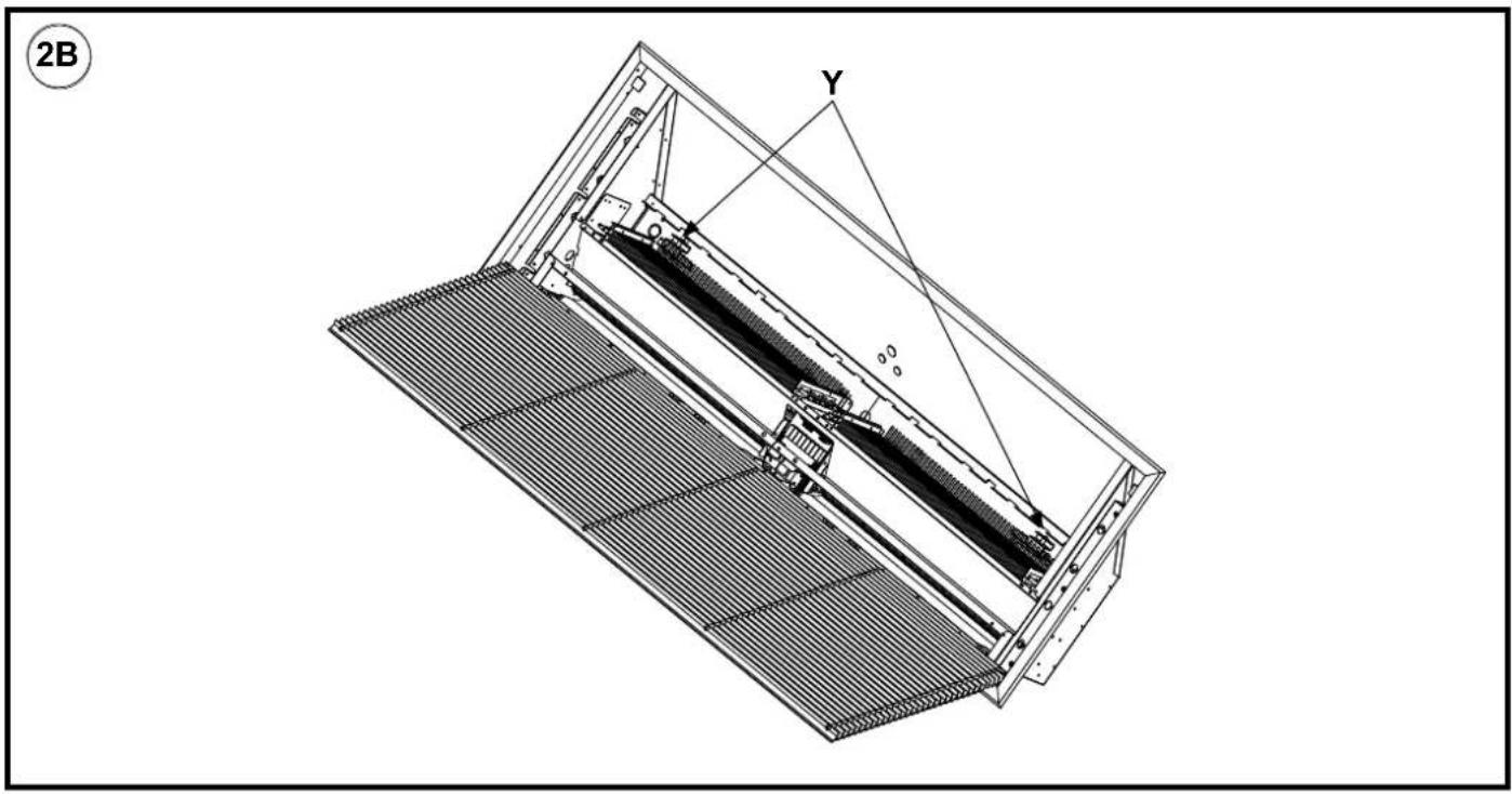
- The inside of the air curtain must be cleaned at a minimum interval of once every 3 months, or more frequently if the weekly inspection deems it necessary. To clean the product open the grills by moving both sliders to the open position ('x' in Fig. 2A) using a flathead screwdriver, allowing the grille to match the position shown in Fig. 2B.
- Once the heater bank has been accessed the unit can be cleaned using a vacuum cleaner with a brush attachment being careful not to disturb or damage the internal wiring or thermal cut-outs. When the element bank has been cleaned, the grill must be closed and secured before the air curtain is turned back on.
- Please note that the motors do not require any additional lubrication.

WARNING: IN ORDER TO AVOID OVERHEATING DO NOT COVER.
This range of air curtains are specifically designed to be recessed into ceiling spaces and above suspended ceilings.
Models
| Model Heat OutputkW | Electrical Supply E | Electrical LoadA(per phase) | WeightKG | Max Installed heightM | |
| AMBIENT / COLD STORE | |||||
| CAB10ARn | a220-240V~1PN | 0.320.53.0 | |||
| CAB15AR | n/a | 220-240V | ~1PN | 0 | 5 25 |
| ELECTRICALLY HEATED | |||||
| CAB10ER | 4.5 / 9.0 | 380-415V ~3PN | 14 | 26 | 3.0 |
| CAB15ER | 6.75 / 13.5 | 380-415V ~3PN | 20 | 35 | 3.0 |
| WATER HEATED (at 82/71 °C - LPHW)** | |||||
| CAB10WR9 | 0220-240V~1PN | 0.3 233.0 | |||
| CAB15WR | 13.5 | 220-240V ~1PN | 0.5 | 32.5 | |
| AMBIENT / COLD STORE | |||||
| DAB10ARn | a220-240V~1PN | n/a31.54.0 | |||
| DAB15AR | n/a | 220-240V | ~1PN | n/a | |
| ELECTRICALLY HEATED | |||||
| DAB10ER | 6.0 / 12.0 | 380-415V ~3PN | 6.0 / 12.0 | 31.5 | 4.0 |
| DAB15ER | 9.0 / 18.0 | 380-415V ~3PN | 9.0 / 18.0 | 43 | 4.0 |
| WATER HEATED (at 82/71 °C - LPHW)** | |||||
| DAB10WR | 12.0 | 220-240V ~1PN | 50 | 31.5 | 4.0 |
| DAB15WR | 18.0 | 220-240V ~1PN | 75 | 43 | 4.0 |
Electrical
The installation of this appliance should be carried out by a competent electrician and be in accordance with the current IEE wiring regulations.
Fixing Positions
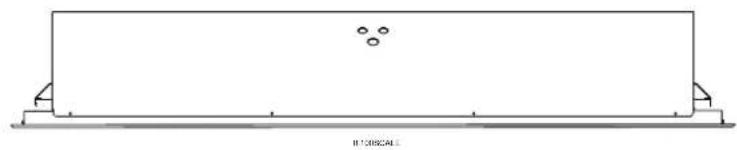
This appliance must be mounted to a solid structure - see Fig. 1 for fixing dimensions and Fig. 5, 6, or 7 for mounting positions and 'Mounting' sections below for fixing details. This appliance should not be mounted less than 1.8m from the floor. The unit must be installed in an area where airflow into and out of the heater is unobstructed.
Mounting into a Standard Ceiling Void
- Side Fixings - Using a suitable ceiling surface, mark off and drill for M8 drops rods. Dimensions can be found on Fig.1. Cut the M8 drop rods to the desired length, taking note of the final position of the appliance relative to the distance to the mounting surface. Mount the drop rods to the ceiling surface. Remove the grill on the appliance. (see Fig. 2) Using suitable lifting equipment raise up the appliance to the drop rods as shown in Fig. 7a & 7b. Connect the appliance to the drop rods using standard M8 lock nuts and washers.
- Top Mounted Inserts - If a suitable (unistrut) structure is available, mark off and drill for M8 threaded bolts. Insert the bolts down through the structure. Dimensions can be found on Fig. 1. Using suitable lifting equipment raise up the appliance to the bolts. Screw the bolts into the threaded inserts on the top of the appliance, and tighten securely.
Electrical connection
All products are fitted with a microprocessor control. Electrical power and control connections are made as shown in Fig.
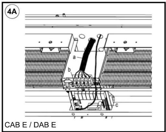
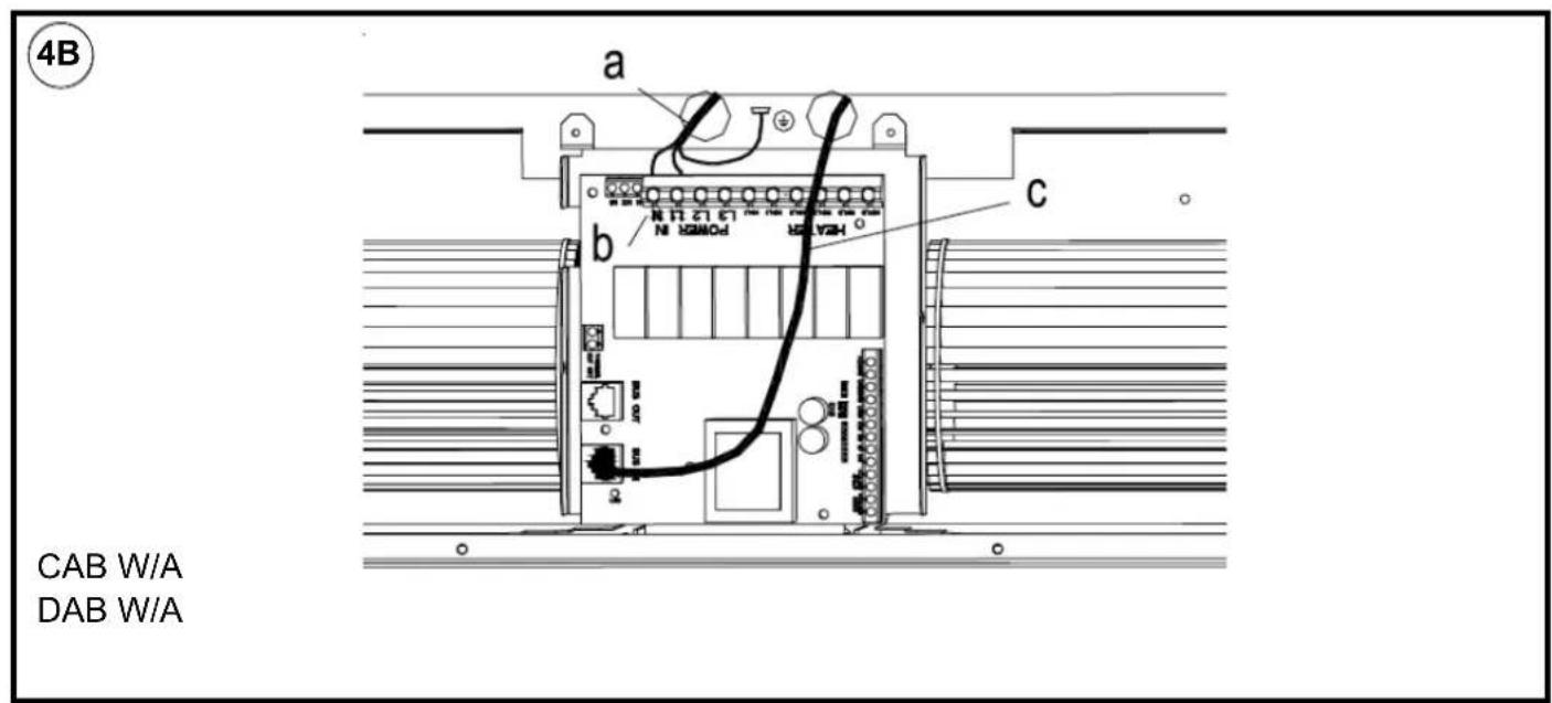
4. Means for disconnection must be incorporated in the fixed wiring in accordance with the wiring rules. In order to access the electrical connections, remove the outlet grilles ('x' in Fig. 2) by undoing the four fasteners in each tile. For the Water heated and Ambient models only, the pressure plate must also be removed.
All Electric Models - Having removed a 'knock out' in the top panel, feed an appropriate supply cable (see 'a' in Fig. 4A) through a suitable cable gland (not supplied) fitted in the top panel and attach to the terminal block (see 'b' in Fig. 4A).
All Water heated and Ambient Models - Having removed a 'knock out' in the top panel, feed an appropriate supply cable (see 'a' in Fig.4B) through a suitable cable gland (not supplied) fitted in the top panel and attach to the PCB (see 'b' in Fig. 4B).
3.0
All Models - A suitable cable (CAT5 or equivalent) for a switch panel (kit ref. - CABC5 for electrically heated models or CABC6 for water heated/ambient models) can be similarly introduced through the top panel and plugged into the circuit board as shown in Fig. 4A & 4B. If the unit is to be operated in conjunction with a door switch, a normally open switch should be wired as per 'D' in Fig. 8 & 9 as appropriate.
Note: If using a door switch, an additional 2 core (low voltage) cable is required between the door switch and the air curtains. If the unit is to be connected to a Building Energy Management System, connections are made as per 'S0, S1, & S2' in Fig. 8 & 9 as appropriate.
Water connection
Models designed for use in conjunction with a low pressure hot water supply should be individually connected (in a parallel circuit) to the flow and return pipe-work. Connections (see 'a' in Fig. 3) are: 12 " BSPT (CAB series) and isolation valves (see 'b' in Fig. 3) should be fitted as close to the air curtain connection points as possible. For commissioning, air bleed valves (see 'c' in Fig. 3) are fitted to the coil, which can be accessed by removal of the ceiling tile - see Fig. 2.
Maximum water supply conditions are 125°C and 8 bar (0.8MPa).
To aid installation, the water coil connections may be moved to either side of the appliance. By removing the water coil and appropriate knockouts the water coil can then be re-inserted into the required orientation. This procedure should be carried out before mounting the appliance.
Switch Panel Installation
The backing box (standard double gang) should be surface mounted onto a suitable wall, alternatively a recessed box can be used (not supplied). Suitable conduit should be used where applicable to carry the cable between the heater and the switch. A CAT5 computer network cable with straight through connections should be used to connect the switch panel to the appliance PCB.
Warning: Ensure cable is secure and the cable path does not come into contact with heater element or other moving parts.
Note: If using a door switch, an additional 2 core (low voltage) cable is required between the door switch and the air curtains. Test all switch settings once installation is complete.
Electrically heated variants
Operation using switch box - CABC5
Switch on electrical supply to the air curtain. Rotate the switch to the desired heat setting. Settings available are;
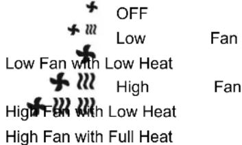
The rocker (auto / manual) switch allows for manual over-ride of a door switch if fi tted. Manual allows the appliance to run at the desired setting, while Auto provides an energy saving feature by shutting down the appliance while the door is closed.
The unit should always be switched to Standby using the switch box control, and not switch off by mains power supply interruption.
When the unit is switched to Standby (via the switch box) the fan will run on for 1 minute without heat to discharge any residual energy from the heating elements.
When first turned on the control will run through a system check. The selected settings will be reached and maintained after a 30 second period.
Thermostatic control
A capillary type thermostat is factory fitted within the unit, as per 'C' in Fig. 8, giving a selection scale of 0-40°C. When the thermostat operates, the power output will reduce depending on the switch setting.
- Fan only - No effect
- Half Heat - Heater will reduce to Fan only
- Full Heat - Heater will reduce to Half Heat
Door switch control (Electric models)
By including a door switch in the circuit (as per 'D' in Fig. 8) the air curtain will respond to door openings as follows:
(1) Door opening will energise the air curtain at the set conditions (switch box settings).
(2) On door closure operation will continue at the set conditions for a further 1 minute.
(3) Between 1 minute and 2 minutes from door closure, set back operation, 12 heat (if heat selected) and 12 fan will activate.
(4) Between 2 minutes and 3 minutes, the fan only ( 12 speed) shut down cycle will be engaged.
(5) After 3 minutes, the air curtain will return to a dormant state until the door is re-opened.
If the door re-opens during this 3 minute run on cycle, the process will restart at (1).
Thermal Safety cut outs
The power supply to the heating elements will be interrupted if one or a combination of the following abnormal events occur:
- Air inlet or outlet grilles are obstructed.
- Internal ventilation is impaired due to build up of dust and fluff.
- Blower unit stalls.
Before resetting the thermal safety cut-outs you must turn the power OFF. Unlock the grille by moving the two sliders into the open position 'x' as shown in Fig. 2A, using a small screw driver or other suitable tool. With the grille partially open disconnect the safety cord to allow the grille to fully open. Then access the reset buttons as shown in 'y' in Fig. 2B. Before re-setting the reason for activation must be determined and corrective action taken.
Low Pressure Hot Water (LPHW) heated Ambient (fan only) variants
Operation using switch box - CABC6
Switch on electrical supply to the air curtain. Rotate the switch to the desired heat setting. Settings available are;
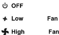
The rocker (auto / manual) switch allows for manual over-ride of a door switch if fitted. Manual allows the appliance to run at the desired setting, while Auto provides an energy saving feature by shutting down the appliance while the door is closed.
The unit should always be switched to Standby using the switch box control, and not switched off by mains power supply interruption. When first turned on the control will run through a system check. The selected settings will be reached and maintained after a 30 second period.
Thermostatic control (optional)
1) A thermostatic regulation valve with a remote sensing bulb (not supplied) can be positioned in the supply water pipe-work to regulate the heat output.
2) An electrical 3-Port Solenoid Valve can also be connected into the system. Please contact your sales or service agent using the contact details provided.
Door switch control (Water heated & Ambient models)
By including a door switch in the circuit (as per 'D' in Fig. 9 the air curtain will respond to door openings as follows:
(1) Door opening will energise the air curtain at the set conditions (switch box settings).
(2) On door closure operation will continue at the set conditions for a further 1 minute.
(3) Between 1 minute and 2 minutes from door closure 12 fan set back operation will activate.
(4) After 2 minutes, the air curtain will return to a dormant state until the door is re-opened. If the door re-opens during this 2 minute run on cycle, the process will re-start at (1).
Wiring Diagrams
CAB & DAB 'E' - Electric models - see Fig. 8
CAB & DAB 'W' / 'A' - Water heated & Ambient models - see Fig. 9
C - Thermostat
D - Door Switch (Optional)
E - Thermal Safety Cut-out Circuit
F - Elements
- BMS Switches (Optional)(S0,S1,S2)
M - Motor
Remote (BMS / BEMS) Operation
Connection to Building Energy Management Control Systems (BEMS) is possible so that remote control of the air curtain can be carried out in conjunction with other equipment. Please refer to the table in Fig. 8 & 9 to make the appropriate connections to the PCB. While the Appliance is connected to BMS/BEMS the supplied controller must be disconnected.
Modular Connection
Refer to instructions provided with the modular linking kit.
Recycling

For electrical products sold within the European Community.
At the end of the electrical products useful life it should not be disposed of with household waste. Please recycle where facilities exist. Check with your Local Authority or retailer for recycling advice in your country.
Cleaning
WARNING: DISCONNECT SUPPLY before carrying out maintenance.
External appearance can be maintained by wiping occasionally with a damp cloth; for stain removal, a weak soap solution can be applied with a cloth and the surface wiped dry. Care must be taken to avoid any moisture ingress into the product.
After Sales Service
Your product is guaranteed for three years from the date of purchase.
Within this period, we undertake to repair or exchange this product free of charge provided it has been installed and operated in accordance with these instructions.
Your rights under this guarantee are additional to your statutory rights, which in turn are not affected by this guarantee.
Please do not return a faulty product to us in the first instance as this may result in loss or damage and delay on providing you with a satisfactory service.
Should you require after sales information or assistance with this product please go to www.dimplex.co.uk when you will find our self help guide by clicking on "After Sales" or ring our helpdesk on 0344 879 3588 (UK) or 01 842 4833 (R.O.I.).
Spare parts are also available on the website
www.dimplex.co.uk
Please retain your receipt as proof of purchase.
DCDimplex®
Customer Helpline: 0344 879 3588
gdhv.customersupport@glendimplex.co.uk
www.dimplex.co.uk
Glen Dimplex Heating and Ventilation
Millbrook House, Grange Drive, Hedge End, Southampton, SO30 2DF
Glen Dimplex Europe, Airport Road, Cloghran, Co. Dublin K67 VE08


- CABR
- DABR
- Important Safety Advice
- DO NOT COVER OR OBSTRUCT the air inlet or outlet grille.
- THIS APPLIANCE MUST BE EARTHED
- INSPECTION
- WARNING: IN ORDER TO AVOID OVERHEATING DO NOT COVER.
- Electrical
- Fixing Positions
- Mounting into a Standard Ceiling Void
- Electrical connection
- Water connection
- Maximum water supply conditions are 125°C and 8 bar (0.8MPa).
- Switch Panel Installation
- Electrically heated variants
- Operation using switch box - CABC5
- The unit should always be switched to Standby using the switch box control, and not switch off by mains power supply interruption.
- Thermostatic control
- Door switch control (Electric models)
- Thermal Safety cut outs
- Low Pressure Hot Water (LPHW) heated Ambient (fan only) variants
- Operation using switch box - CABC6
- Thermostatic control (optional)
- Door switch control (Water heated & Ambient models)
- Wiring Diagrams
- Remote (BMS / BEMS) Operation
- Modular Connection
- Recycling
- Cleaning
- WARNING: DISCONNECT SUPPLY before carrying out maintenance.
- After Sales Service
Brand : DIMPLEX
Model : CAB15AR
Category : Air conditioner