
DOMIcondens F 24 - Water heaters and boilers FERROLI - Free user manual and instructions
Find the device manual for free DOMIcondens F 24 FERROLI in PDF.


| Product Type | Wall-mounted gas condensing combi boiler |
| Model | DOMIcondens F 24 |
| Brand | Ferroli |
| Heating Output (Nominal) | 24 kW |
| DHW Output (Nominal) | 24 kW |
| Dimensions (H x W x D) | 700 x 400 x 300 mm |
| Weight | 30 kg |
| Power Supply | 230 V / 50 Hz |
| Gas Type | Natural gas (G20) / LPG (G30/G31) convertible |
| Energy Class | Class A |
| Main Functions | Central heating and domestic hot water production |
| Control Panel | Digital display with push buttons |
| Modulating Burner | Yes, fully modulating |
| Pump | High-efficiency circulator pump |
| Expansion Vessel | 8 L capacity |
| Maintenance Frequency | Annual service recommended |
| Cleaning | External surfaces with damp cloth; internal by qualified technician |
| Safety Devices | Overheat protection, flame failure device, water pressure switch |
| Spare Parts Availability | Yes, through Ferroli service network |
| Reparability | Modular design for easy replacement of components |
| Warranty | 2 years (standard) |
| Certification | CE, ErP compliant |
| Installation Type | Room-sealed (C type) or open flue (B type) - check local regulations |
| Operating Temperature Range | Heating: 30-80°C; DHW: 35-60°C |
| Noise Level | < 50 dB(A) |
Frequently Asked Questions - DOMIcondens F 24 FERROLI
User questions about DOMIcondens F 24 FERROLI
0 question about this device. Answer the ones you know or ask your own.
Ask a new question about this device
Download the instructions for your Water heaters and boilers in PDF format for free! Find your manual DOMIcondens F 24 - FERROLI and take your electronic device back in hand. On this page are published all the documents necessary for the use of your device. DOMIcondens F 24 by FERROLI.
USER MANUAL DOMIcondens F 24 FERROLI
- Carefully read the instructions contained in this instruction booklet.
• After boiler installation, inform the user regarding its operation and give him this manual, which is an integral and essential part of the product and must be kept with care for future reference.
• Installation and maintenance must be carried out by professionally qualified personnel, according to current regulations and the manufacturer's instructions. Do not carry out any operation on the sealed control parts. - Incorrect installation or inadequate maintenance can result in damage or injury. The Manufacturer declines any liability for damage due to errors in installation and use or failure to follow the instructions.
- Before carrying out any cleaning or maintenance operation, disconnect the unit from the power supply using the system switch and/or the special cut-off devices.
- In case of a fault and/or poor operation, deactivate the unit and do not attempt to repair it or directly intervene. Contact professionally qualified personnel. Repair/replacement of the products must only be carried out by professionally qualified using original spare parts. Failure to comply with the above could affect the safety of the unit.
- This unit must only be used for its intended purpose. Any other use is considered improper and therefore dangerous.
• The packing materials are potentially hazardous and must not be left within the reach of children. - The images given in this manual are a simplified representation of the product. In this representation there may be slight and insignificant differences with respect to the product supplied.
2. OPERATING INSTRUCTIONS
2.1 Introduction
Dear Customer,
DOMIcondens F is a high-efficiency sealed chamber condensing heat generator for heating and hot water production running on natural gas or LPG, and equipped with a microprocessor control system.
2.2 Control panel

fig. 1 - Control panel
Key
1 = Domestic hot water temperature setting
3 = Heating system temperature setting
5 = Display
6 = Summer/Winter mode selection - Reset button
7 = Unit On/Off - Eco/Comfort mode selection button
9 = DHW mode
10 = Summer mode
11 = Temperature or faults
12 = Eco (Economy) mode
13 = Heating
15 = Burner On and actual power
16 = Clock prearrangement
Indication during operation
Heating
A heating demand (generated by the Room Thermostat or Remote Timer Control) is indicated by flashing of the hot air above the radiator on the display.
Domestic hot water (DHW)
A DHW demand (generated by drawing domestic hot water) is indicated by flashing of the hot water under the tap on the display.
2.3 Lighting and turning off
Connection to the power supply
- During the first 5 seconds the display shows the card software version.
- Open the gas cock ahead of the boiler.
- The boiler is now ready to operate automatically whenever hot water is drawn or in case of a room thermostat demand.
Boiler lighting and shutdown
Press the on/off button (detail 7 - fig. 1) for 5 seconds.

fig. 2 - Turning the boiler off
When the boiler is turned off, the PCB is still powered. Domestic hot water and heating are disabled. The antifreeze system remains activated. To relight the boiler, press the on/off button (detail 7 fig. 1) again for 5 seconds.
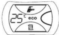
fig. 3
The boiler will be immediately ready to operate whenever domestic hot water is drawn or in case of a room thermostat demand.

The antifreeze system does not work when the power and/or gas to the unit are turned off. To avoid damage caused by freezing during long idle periods in winter, it is advisable to drain all water from the boiler, DHW circuit and system; or drain just the DHW circuit and add a suitable antifreeze to the heating system, complying with that prescribed in sec. 3.3.
2.4 Adjustments
Summer/Winter Switchover
Press the summer/winter button (detail 6 - fig. 1) for 2 seconds.
The display activates the Summer symbol (detail 10 - fig. 1): the boiler will only deliver domestic hot water. The antifreeze system remains activated.
To deactivate the Summer mode, press the summer/winter button (detail 6 - fig. 1) again for 2 seconds.
Heating temperature setting
Use the heating buttons (detail 3 - fig. 1) to adjust the temperature from a min. of 30irc C to a max. of 85irc C; it is advisable not to operate the boiler below 45irc C.

fig. 4
Hot water temperature adjustment
Use the DHW buttons (detail 1 - fig. 1) to adjust the temperature from a min. of 40°C to a max. of 55°C.

fig. 5
Room temperature adjustment (with optional room thermostat)
Using the room thermostat, set the temperature required in the rooms. If the room thermostat is not installed, the boiler will keep the system at the set system delivery setpoint temperature.
Room temperature adjustment (with optional remote timer control)
Using the remote timer control, set the required temperature in the rooms. The boiler will adjust the system water according to the required room temperature. For operation with remote timer control, please refer to the relevant instruction manual.
ECO/COMFORT selection
The unit has a function that ensures a high domestic hot water delivery speed and maximum comfort for the user. When the device is activated (COMFORT mode), the water contained in the boiler is kept hot, therefore ensuring immediate availability of hot water on opening the tap, without waiting times.
The device can be deactivated by the user (ECO mode) by pressing the eco/comfort button (detail 7 - fig. 1) with the boiler in standby mode. In ECO mode the display activates the ECO symbol (detail 12 - fig. 1). To activate COMFORT mode, press the eco/comfort button (detail 7 - fig. 1) again.
Adjustments from Remote Timer Control

If the Remote Timer Control (optional) is connected to the boiler, the above adjustments are managed according to that given in table 1.
Table. 1
| Heating temperature setting | Adjustment can be made from the Remote Timer Control menu and the boiler control panel. |
| Hot water temperature adjustment | Adjustment can be made from the Remote Timer Control menu and the boiler control panel. |
| Summer/Winter Switchover | Summer mode has priority over a possible Remote Timer Control heating demand. |
| Eco/Comfort selection | Adjustment can only be made from the boiler control panel. |
Water system pressure regulation
The filling pressure read on the boiler water gauge with the system cold must be approx 1.0 bar. If the system pressure falls to values below minimum, the boiler stops and fault F37 is displayed.
3. INSTALLATION
3.1 General Instructions

This unit must only be used for its intended purpose. This unit is designed to heat water to a temperature below boiling point and must be connected to a heating system and/or a water supply system for domestic use, compatible with its performance, characteristics and its heating capacity. Any other use is deemed improper.
BOILER INSTALLATION MUST ONLY BE CARRIED OUT BY QUALIFIED PERSONNEL, IN ACCORDANCE WITH ALL THE INSTRUCTIONS GIVEN IN THIS TECHNICAL MANUAL, THE PROVISIONS OF CURRENT LAW, THE PRESCRIPTIONS OF THE TECHNICAL STANDARDS (BS), ANY LOCAL REGULATIONS AND THE RULES OF PROPER WORKMANSHIP.
Incorrect installation can cause damage or injury for which the manufacturer declines any responsibility.
Installation of this unit must be carried out in strict compliance with the present instructions and the following regulations applicable in Great Britain.
Gas Safety Regulations (Installations & Use).
Local Building Regulations..
The Building Regulations (Part L).
The Buildings Standards (Scotland - Consolidated) Regulations. British Standards Codes of Practice (BSI):
B.S. 5440 Detail 1 Flues
B.S. 5440 Detail 2 Air supply and ventilation
B.S. 5449 Systems for hot water production with forced circulation
B.S. 6798 ...... Installation of gas-fired boilers for hot water
B.S. 6891 ...... Gas systems
B.S. 7671 ..... IEE wiring system regulations
B.S. 4814 .... Specifications for expansion tanks
B.S. 5482 ..... LPG systems
B.S. 7593 ...... Water treatment in central heating systems for domestic hot water production
B.S. 5546 ..... Installation of systems for domestic hot water production
Model Water By-Laws
B.S. 5955-8 ...... Installation of plastic pipes
For Northern Ireland, observe the current applicable regulations.
Safe handling of materials
Pay attention when handling the boiler insulation panels because the material they are made of could irritate the skin. No part of the boiler contains asbestos, mercury or CFC's.
Advice for transport and handling
For lifting and transport always take suitable safety precautions: keep your back straight, bend knees, do not turn your body, move feet, avoid bending forward or sideways and keep the load as close as possible to your body.
If possible, use a trolley or other suitable means to carry the boiler.
Grip the boiler firmly and, before lifting it, try and find the point where the load is concentrated in order to establish the centre of gravity and suitably reposition yourself.
3.2 Place of installation
The combustion circuit is sealed with respect to the place of installation room, therefore the unit can be installed in any room. However, the place of installation must be adequately ventilated to prevent the creation of dangerous conditions in case of even small gas leaks. This safety regulation is laid down by EEC Directive no. 90/396 for all gas units, including those with sealed chamber.
The unit is suitable for operation in a partially protected place in conformity with EN 297/A6, with minimum temperature -5ircC . If equipped with the special antifreeze kit, it can be used with minimum temperatures to -15ircC . The boiler must be installed is a protected place, e.g. under the slope of a roof, inside a balcony or in a sheltered recess.
The place of installation must in any case be free of dust, flammable materials or objects or corrosive gases.
The boiler is arranged for wall mounting and comes standard with a hooking bracket. The wall fixing must ensure a stable and effective support for the generator.

If the unit is enclosed in a cabinet or mounted alongside, a space must be provided for removing the casing and for normal maintenance operations
3.3 Plumbing connections
Important
The heating capacity of the unit must be previously established by calculating the building's heat requirement according to the current regulations. To ensure proper operation and long boiler life, the plumbing system must be adequately sized and complete with all the necessary accessories, including a room thermostat, a thermostallable valve (TRV) etc. The system delivery and return pipes must have a diameter of at least 22 mm for the first 3 m of length from the unit.
If the system delivery and return pipes follow a path where air pockets can form in certain places, it is advisable to install vent valves at these points. Also, type "A" drain cocks must be installed at the lowest points in the system to allow complete emptying.

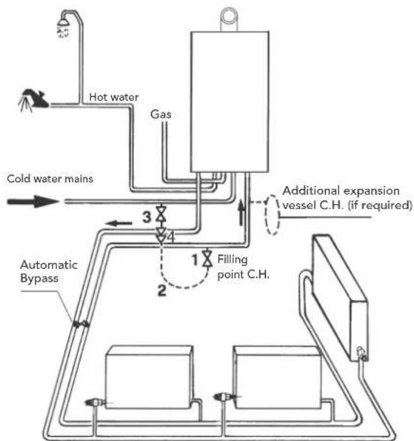
An automatic bypass with flow rate of at least 6 l/min. must be installed (connected as far away as possible from the boiler) if radiators with thermostatic valves have been connected.
flowchart
graph TD
    A["Hot water"] --> B["Gas"]
    B --> C["Cold water mains"]
    C --> D["Automatic Bypass"]
    D --> E["Filling point C.H."]
    E --> F["Additional expansion vessel C.H. (if required)"]
    style A fill:#f9f,stroke:#333
    style B fill:#ccf,stroke:#333
    style C fill:#cfc,stroke:#333
    style D fill:#fcc,stroke:#333
    style E fill:#cff,stroke:#333
    style F fill:#ffc,stroke:#333
fig. 6 - Automatic bypass connection
The temperature drop between the delivery manifold and the return to the boiler should not exceed 20irc C.

Do not use the water system pipes to earth electrical appliances.
Before installation, carefully wash all the pipes of the heating system to remove any residuals or impurities that could affect proper operation of the unit (as required by BS 7593 Building regs Doc L).
Carry out the connections to the unit as indicated in fig. 7.

fig. 7 - Water connections
Shutoff valve kit
Make sure to install the shutoff valves (supplied) between the boiler and the heating system, allowing the boiler to be isolated from the system if necessary.

The safety valve outlet must be connected to a copper pipe of 15 mm diameter with continuous fall from the boiler to run off the system water in case of overpressure in the heating circuit. Otherwise, if the discharge valve cuts in and floods the room, the boiler manufacturer cannot be held liable. The drain must be run to the outside of the building to avoid the risk of damage or injury due to the hot water in case of overpressure in the system.
Make the boiler connection in such a way that its internal pipes are free of stress. If a non-return valve is installed also on the DHW circuit (if provided for), it is necessary to install a safety valve between the boiler and the circuit (with the non-return valve at least 3 m from the boiler) or an expansion tank for domestic use.
For installation, follow the instructions contained in the kit.
Replenishing water
It is necessary to provide for replenishing of the water lost by the sealed system. Refer to standard BS6798 for the methods of filling and replenishing water in sealed systems. There must not be a direct connection between the central heating system of the boiler and the water mains. For the use of water coming from the water mains and direct pressurisation of the system, refer to the local water management by-laws. This connection must be interrupted after use.
The boiler comes standard with the connection (filling loop) shown in fig. 8. For installation, follow the instructions given on the instruction sheet enclosed with the kit
To replenish the water in the system:
- Fix the removable connection "1" between the two valves.
- Open the two cocks "2 and 3" until the pressure read on the water gauge is approx. 1 bar.
- Close the two cocks "2 and 3".
- At the end of the operation, remove the removable connection "1".
Reference is made to the provisions contained in the water management by-laws.

fig. 8 - Filling loop
Water treatment
If water treatment is necessary, Ferroli recommends the exclusive use of specific products such as Fernox or Sentinel to be applied according to the producer's instructions. For further information, please contact:
Fernox Manufacturing Co. LTD.
Cookson Electronics. Forsyth Road
Sheerwater, Woking, Surrey, GU21 5RZ
Tel.: 0870 8700362
Sentinel Performance Solutions Ltd
The Heath Business & Technical Park
Runcorn, Cheshire WA7 4QX
Tel.: 0151 424 5351

If the boiler is installed in an existing system, any unsuitable additives must be removed by thoroughly cleaning the system. Cleaning of all the systems must be done in compliance with the requirements of standard B.S. 7593.

In areas with hard water, treatment may be necessary in order to prevent scale from forming in the boiler.

Make sure to use the water treatment product in the right concentration, according to the producer's instructions.
3.4 Gas connection
The gas must be connected to the relevant connection (see fig. 7) in conformity with current standards, with a rigid metal pipe or with a continuous surface flexible s/steel tube, installing a gas cock between the system and boiler. Make sure all the gas connections are tight.
3.5 Electrical connections

The unit must be connected to an efficient earthing system in accordance with current safety standards. Have the efficiency and suitability of the earthing system checked by professionally qualified personnel; the Manufacturer declines any liability for damage caused by failure to earth the system.
The boiler is prewired and provided with a "Y" type cable (without plug) for connection to the electric line. The connections to the grid must be made with a permanent connection and equipped with a double-pole switch with contact opening of at least 3 mm, installing fuses of max. 3A between the boiler and the line. Make sure to respect the polarities (LINE: brown wire / NEUTRAL: blue wire / EARTH: yellow/green wire) in connections to the electric line.

The user must not replace the unit's power cable. If damaged, switch off the unit and have the cable replaced only by professionally qualified personnel. If replacing the power cable, only use "HAR H05 VV-F" 3x0.75 mm2 cable with max. outside diameter of 8 mm.
Room thermostat (optional)

IMPORTANT: THE ROOM THERMOSTAT MUST HAVE VOLTAGE-FREE CONTACTS. CONNECTING 230V TO THE ROOM THERMOSTAT TERMINALS WILL PERMANENTLY DAMAGE THE PCB.
When connecting a time control or timer, do not take the power supply for such devices from their cutoff contacts. Their power supply must be taken with a direct connection from the mains or with batteries, depending on the type of device.
Accessing electrical terminal block
Follow the instructions given in fig. 9 to access the electrical connection terminal block. The layout of the terminals for the various connections is also given in the wiring diagram in fig. 21.
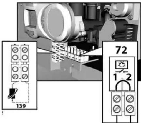
fig. 9 - Accessing the terminal block
3.6 Fume ducts
Important
The unit is "type C" with sealed chamber and forced draught; the air inlet and fume outlet must be connected to one of the following extraction/suction systems. Before installation, check and carefully observe the above prescriptions. Also, comply with the provisions concerning the positioning of wall and/or roof terminals and the minimum distances from windows, walls, vents, etc.
Expansion

For fume exhaust pipes longer than 1 metre, during installation take in account the natural expansion of the materials when the boiler is operating.
To prevent any deformation, leave an expansion space of approx. 2 ÷ 4 mm for every metre of pipe.
Baffles
Boiler operation requires fitting the baffles supplied with the unit, according to that given in the following tables.
Before inserting the fume exhaust pipe, check the presence of the right baffle (when it is to be used) and that it is correctly positioned. The boilers are fitted standard with the smallest diameter baffle. To replace the baffle (ref. 1 - fig. 10), proceed as indicated in fig. 10.

natural_image
Technical illustration of a mechanical assembly with exploded view and close-up detail (no text or symbols)fig. 10
Connection with coaxial pipes
Standard coaxial installation
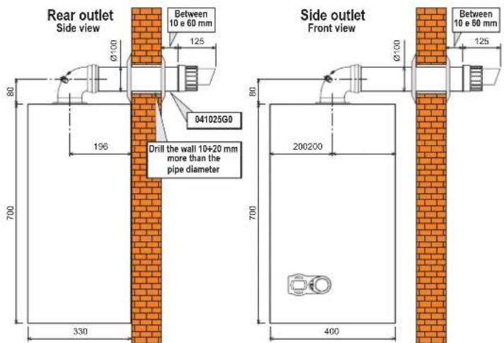
fig. 11 - Standard coaxial installation
Other connections coaxial

flowchart
graph TD
    A["C12"] --> B["C32"]
    B --> C["C32"]
    C --> D["C32"]
    D --> E["C12"]
    E --> F["C12"]
    F --> G["C12"]
    G --> H["C12"]
    H --> I["C12"]
    I --> J["C12"]
    J --> K["C12"]
    K --> L["C12"]
    L --> M["C12"]
    M --> N["C12"]
    N --> O["C12"]
    O --> P["C12"]
    P --> Q["C12"]
    Q --> R["C12"]
    R --> S["C12"]
    S --> T["C12"]
    T --> U["C12"]
    U --> V["C12"]
    V --> W["C12"]
    W --> X["C12"]
    X --> Y["C12"]
    Y --> Z["C12"]
    Z --> AA["C12"]
    AA --> AB["C12"]
    AB --> AC["C12"]
    AC --> AD["C12"]
    AD --> AE["C12"]
    AE --> AF["C12"]
    AF --> AG["C12"]
    AG --> AH["C12"]
    AH --> AI["C12"]
    AI --> AJ["C12"]
    AJ --> AK["C12"]
    AK --> AL["C12"]
    AL --> AM["C12"]
    AM --> AN["C12"]
    AN --> AO["C12"]
    AO --> AP["C12"]
    AP --> AQ["C12"]
    AQ --> AR["C12"]
    AR --> AS["C12"]
    AS --> AT["C12"]
    AT --> AU["C12"]
    AU --> AV["C12"]
    AV --> AW["C12"]
    AW --> AX["C12"]
    AX --> AY["C12"]
fig. 12 - Examples of connection with coaxial pipes ( = Air / = Pulses)
For coaxial connection, fit the unit with one of the following starting accessories. For the wall hole dimensions, refer to the figure on the cover. Any horizontal sections of the fume exhaust must be kept sloping slightly towards the outside, to prevent possible condensate from flowing back towards the unit.

041002X0
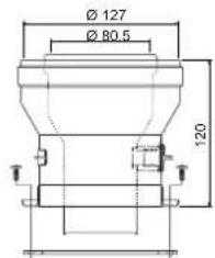
041006X0

041001X0
fig. 13 - Starting accessory for coaxial ducts
Table. 2 - Baffles for coaxial ducts
| Coaxial 60/100 Coaxial 80/125 | |||
| Max. permissible length 6 m 12 m | |||
| Reduction factor 90° bend 1 m 0.5 m | |||
| Reduction factor 45° bend 0.5 m 0.25 m | |||
| Baffle to use | 0 ÷ 2 m 45 | 0 ÷ 6 m | 45 |
| 2 ÷ 4 m 50 | 6 ÷ 12 m | no baffle | |
| 4 ÷ 6 m | no baffle | ||
Connection with separate pipes



fig. 14 - Examples of connection with separate pipes (→ = Air / → = Fumes)
For the connection of separate ducts, fit the unit with the following starting accessory:

fig. 15 - Starting accessory for separate ducts
Before proceeding with installation, check the baffle to be used and make sure the maximum permissible length has not been exceeded, by means of a simple calculation:
- Completely establish the layout of the system of split flues, including accessories and outlet terminals.
- Consult the table 4 and identify the losses in m eq (equivalent metres) of every component, according to the installation position.
- Check that the sum total of losses is less than or equal to the maximum permissible length in table 3.
Table. 3 - Baffles for separate ducts
| Separate ducts | ||
| Max. permissible length | 55 meq | |
| Baffle to use | 0 ÷ 15 meq | ∅ 45 |
| 15 ÷ 35 meq | ∅ 50 | |
| 35 ÷ 55 meq | No baffle | |
Table. 4 - Accessories
| Losses in meq | ||||||
| Air inlet | Fume exhaust | |||||
| Vertical | Horizontal | |||||
| ∅ 80 | PIPE | 1 m M/F | 1KWMA83W | 1.0 | 1.5 2.0 | |
| BEND | 45" M/F | 1KWMA85W | 1.2 | 1.8 | ||
| 90" M/F | 1KWMA01W | 1.5 | 2.0 | |||
| PIPE SECTION | with test point | 1KWMA70W | 0.3 | 0.3 | ||
| TERMINAL | air, wall | 1KWMA85A | 2.0 | - | ||
| fumes, wall with antiwind | 1KWMA86A | - | 5.0 | |||
| FLUE | Split air/fumes 80/80 | 1KWMA84U | - | 12.0 | ||
3.7 Condensate drain connection
The boiler is equipped with an internal trap for condensate draining. Fit the inspection union A and the flexible tube B, pressing it on about 3 cm. Fill the trap with approx. 0.5 l of water and connect the flexible tube to the drainage system.

natural_image
3D mechanical assembly diagram showing labeled components A and B, with colored components and no visible text or symbols.fig. 16 - Condensate drain connection
4. SERVICE AND MAINTENANCE
4.1 Adjustments
Gas conversion
The unit can operate on natural gas or LPG and is factory-set for use with one of these two gases, as clearly shown on the packing and on the dataplate. Whenever a different gas to that for which the unit is preset has to be used, a conversion kit will be required, proceeding as follows:
- Replace the nozzles at the main burner, fitting the nozzles specified in the technical data table in cap. 5, according to the type of gas used
-
Modify the parameter for the type of gas:
-
put the boiler in standby mode
- press the reset button (detail 6 - fig. 1) for 10 seconds: the display shows "TS" flashing
- press the reset button (detail 6 - fig. 1): the display shows "P01".
- Press the DHW buttons (detail 1 - fig. 1) to set parameter 00 (for operation with natural gas) or 01 (for operation with LPG).
• Press the reset button (detail 6 - fig. 1) for 10 seconds. -
the boiler will return to standby mode
-
Adjust the minimum and maximum pressures at the burner (ref. relevant section), setting the values given in the technical data table for the type of gas used
- Apply the sticker contained in the conversion kit, near the dalaplate as proof of the conversion.
TEST mode activation
Press the heating buttons (detail 3 - fig. 1) at the same time for 5 seconds to activate the TEST mode. The boiler lights at the maximum heating power set as described in the following section.
The heating and DHW symbols (fig. 17) flash on the display; the heating power will be displayed alongside.

fig. 17 - TEST mode (heating power = 100%)
To deactivate the TEST mode, repeat the activation sequence.
The TEST mode is automatically disabled in any case after 15 minutes.
Adjustment of pressure at burner
Since this unit has flame modulation, there are two fixed pressure values: the minimum and maximum, which must be those given in the technical data table according to the type of gas.
- Connect a suitable pressure gauge to pressure point "B" downstream of the gas valve.
- Disconnect the pressure compensation tube "N".
- Remove the protection cap "D".
- Operate the boiler in TEST mode.
- Adjust the maximum pressure by turning the screw and anticlockwise to decrease it. "G" clockwise to increase the pressure
- Disconnect one of the two fastons "C" from the moduleg "F" on the gas valve.
- Adjust the minimum pressure by turning the screw and anticlockwise to decrease it. "E" clockwise to increase the pressure
- Turn the burner on and off, checking that the minimum pressure remains stable.
- Reconnect the faston "C" detached from the modureg "F" on the gas valve
- Check that the maximum pressure has not changed
- Reconnect the pressure compensation tube "N".
- Refit the protection cap "D".
• To end the TEST mode, repeat the activation sequence or wait 15 minutes.

After checking or adjusting the pressure, make sure to seal the adjustment screw with paint or a specific seal.

fig. 18 - Gas valve
A Upstream pressure point
B Downstream pressure point
C Modureg electrical connection
D Protection cap
E Minimum pressure adjustment
F Modureg
G Minimum pressure adjustment
H Compensation tube connection
I Gas valve electrical connection
L Sealed chamber
M Pressure gauge
N Compensation tube
R Gas outlet
S Gas inlet
Heating power adjustment
To adjust the heating power, switch the boiler to TEST mode (see sec. 4.1). Press the heating buttons detail 3 - fig. 1 to increase or decrease the power (min. = 00 - max. = 100). Press the reset button within 5 seconds and the max. power will remain that just set. Exit TEST mode (see sec. 4.1).
Lighting power adjustment
To adjust the lighting power, switch the boiler to TEST mode (see sec. 4.1). Press the DHW buttons (detail 1 - fig. 1) to increase or decrease the power (min. = 00 - max. = 60). Press the reset button within 5 seconds and the lighting power will remain that just set. Exit TEST mode (see sec. 4.1).
4.2 Startup
Before lighting the boiler
- Check the seal of the gas system.
- Check correct prefilling of the expansion tank.
- Fill the water system and make sure all air contained in the boiler and the system has been vented.
• Make sure there are no water leaks in the system, DHW circuits, connections or boiler. - Check correct connection of the electrical system and efficiency of the earthing system.
• Make sure the gas pressure for heating is that required.
• Make sure there are no flammable liquids or materials in the immediate vicinity of the boiler
Checks during operation
- Switch the unit on.
- Check the tightness of the fuel circuit and water systems.
- Check the efficiency of the flue and air/fume ducts while the boiler is working.
• Make sure the water is circulating properly between the boiler and the systems. - Make sure the gas valve modulates correctly in the heating and domestic hot water production stages.
- Check correct boiler lighting by performing various tests, turning it on and off with the room thermostat or remote control.
• Make sure the fuel consumption indicated on the meter matches that given in the technical data table in cap. 5. - Make sure that with no demand for heating, the burner lights correctly on opening a hot water tap. Check that in heating mode, on opening a hot water tap, the heating circulating pump stops and there is regular production of hot water.
- Make sure the parameters are programmed correctly and carry out any required customisation (compensation curve, power, temperatures, etc.).
4.3 Maintenance
Periodical check
To ensure correct operation of the unit over time, have qualified personnel carry out a yearly check, providing for the following:
- The control and safety devices (gas valve, flow meter, thermostats, etc.) must function correctly.
• The fume exhaust circuit must be perfectly efficient.
(Sealed chamber boiler: fan, pressure switch, etc. -The sealed chamber must be tight: seals, cable glands, etc.)
(Open chamber boiler: anti-backflow device, fume thermostat, etc.)
- The air/fume terminal and ducts must be free of obstructions and leaks
- The burner and exchanger must be clean and free of deposits. Do not use chemical products or wire brushes for cleaning.
• The electrode must be free of scale and properly positioned.
• The gas and water systems must be tight - The water pressure in the system when cold must be approx. 1 bar; otherwise bring it to that value.
• The circulating pump must not be blocked.
• The expansion tank must be filled.
• The gas flow and pressure must match that given in the respective tables.
4.4 Troubleshooting
Diagnostics
The boiler is equipped with an advanced self-diagnosis system. In case of a boiler fault, the display will flash together with the fault symbol (detail 11 - fig. 1) indicating the fault code.
There are faults that cause permanent shutdown (marked with the letter "A"): to restore operation, press the RESET button (detail 6 - fig. 1) for 1 second or RESET on the optional remote timer control if installed; if the boiler fails to start, it is necessary to eliminate the fault.
Faults marked with the letter "F" cause temporary shutdowns that are automatically reset as soon as the value returns within the boiler's normal working range.
Table of faults
Table. 5 - Fault list
| Fault code | Fault Possible cause Cure | ||
| A01 | No burner ignition | Excessive condensate level | Empty / clean the trap |
| No gas | Check the regular gas flow to the boiler and that the air has been eliminated from the pipes | ||
| Ignition/cetection electrode fault | Check the wiring of the electrode and that it is correctly positioned and free of any deposits | ||
| Faulty gas valve | Check the gas valve and replace it if necessary | ||
| A02 | Flame present signal with burner off | Electrode fault Check the nonisation electrode wiring | |
| Card fault Check the card | |||
| A03 | Overtemperature protection activation | Heating sensor damaged | Check the correct positioning and operation of the heating sensor |
| No water circulation in the system | Check the circulating pump | ||
| Air in the system Vent the system | |||
| F05 | Air pressure switch (fails to close contacts within 20 sec. of fan activation) | Air pressure switch contact open | Check the pressure switch / Fan / Fan socket |
| Incorrect air pressure switch wiring | Check the wiring | ||
| Wrong baffle | Check correct ∅ | ||
| Flue costructured or not correctly sized | Check the length of the flues / Clean the flues | ||
| Air pressure switch (fails to close contacts within 20 sec. of fan activation) due to activation of the fume thermostat | Exchangers dirty (clogged on water side) | Clean the exchangers | |
| Faulty water circulation | |||
| A06 | No flame after the ignition stage | Low pressure in the gas system | Check the gas pressure |
| Burner minimum pressure setting | Check the gas pressures | ||
| F10 | Delivery sensor 1 fault | Sensor damaged | Check the wiring or replace the sensor |
| Wiring shorted | |||
| Wiring disconnected | |||
| F11 | DHW sensor fault | Sensor damaged | Check the wiring or replace the sensor |
| Wiring shorted | |||
| Wiring disconnected | |||
| Fault code | Fault | Possible cause | Cure |
| F14 | Delivery sensor 2 fault | Sensor damaged | Check the wiring or replace the sensor Wiring |
| Wiring disconnected | |||
| A15 | Air pressure switch (fails to close contacts within 20 sec. of fan activation) | Fault F05 generated 5 times in the last 24 hours | See fault F05 |
| F34 | Supply voltage under 170V. Electric mains trouble Check the electrical system | ||
| F35 | Faulty mains frequency Electric mains trouble Check the electrical system | ||
| F37 | Incorrect system water pressure | Pressure too low Fill the system | |
| Water pressure switch damaged or not connected | Check the sensor | ||
| A41 | Sensor positioning | Delivery sensor or DHW sensor delached from the pipe | Check the correct positioning and operation of the sensors |
| F42 | Heating sensor fault Sensor damaged Re | Replace the sensor | |
| F43 | Exchanger protection activation. | No system H2O circulation | Check the circulating pump |
| Air in the system Vent the system | |||
| F50 | Modureg fault Wiring disconnected Check the wiring / Gas valve | ||
- TECHNICAL DATA AND CHARACTERISTICS

fig. 19 - General view

line
| Q [l/h] | H [m H₂O] (Line 1) | H [m H₂O] (Line 2) | H [m H₂O] (Line 3) | H [m H₂O] (Line A) | | ------- | ------------------ | ------------------ | ------------------ | ------------------ | | 0 | 2.7 | 4.2 | 5.0 | - | | 500 | 0.5 | 3.0 | 4.5 | - | | 1.000 | - | 2.0 | 4.0 | - | | 1.500 | - | 1.0 | 3.5 | - | | 2.000 | - | 0.0 | 3.0 | 4.0 |fig. 20 - Circulating pumps Head/Pressure losses
A = Boiler pressure losses - 1, 2 and 3 = Circulating pump speed

Important: Before connecting the room thermostat or the remote timer control, remove the jumper on the terminal block.
| Date | Unit | DOMIcondens F 24 | DOMIcondens F 28 | |
| Max. heating capacity | kW | 23.7 | 28.0 | (Q) |
| Min. heating capacity | kW | 10.0 | 10.0 | (Q) |
| Max. Heat Output in heating (80/60°C) | kW | 22.9 | 27 | (P) |
| Min. Heat Output in heating (80/60°C) | kW | 9.2 | 9.2 | (P) |
| Max. Heat Output in heating (50/30°C) | kW | 24.5 | 29 | |
| Min. Heat Output in heating (50/30°C) | kW | 9.6 | 9.6 | |
| Max. Heat Output in hot water production | kW | 23.1 | 27.3 | |
| Min. Heat Output in hot water production | kW | 9.2 | 9.2 | |
| Burner nozzles G20 | no. x ∅ | 11 x 1.35 | 11 x 1.35 | |
| Gas supply pressure G20 | mbar | 20 | 20 | |
| Max. pressure at burner G20 | mbar | 10 | 13.5 | |
| Min. pressure at burner G20 | mbar | 2 | 2 | |
| Max. gas delivery G20 | m3/h | 2.64 | 2.96 | |
| Min. gas delivery G20 | m3/h | 1.06 | 1.06 | |
| Burner nozzles G31 | no. x ∅ | 11 x 0.82 | 11 x 0.82 | |
| Gas supply pressure G31 | mbar | 37 | 37 | |
| Max. pressure at burner G31 | mbar | 29 | 35 | |
| Min. pressure at burner G31 | mbar | 5 | 5 | |
| Max. gas delivery G31 | kg/h | 1.96 | 2.19 | |
| Min. gas delivery G31 | kg/h | 0.76 | 0.78 | |
| Efficiency class Directive 92/42 EEC | - | ★★★★★ | ||
| NOx emission class | - | 3 | 3 | (NOx) |
| Max. working pressure in heating | bar | 3 | 3 | (PMS) |
| Min. working pressure in heating | bar | 0.8 | 0.8 | |
| Max. heating temperature | °C | 90 | 90 | (Imax) |
| Heating water content | litres | 1.5 | 1.5 | |
| Heating expansion tank capacity | litres | 8 | 8 | |
| Heating expansion tank prefilling pressure | bar | 1 | 1 | |
| Max. working pressure in hot water production | bar | 9 | 9 | (PMW) |
| Min. working pressure in hot water production | bar | 0.25 | 0.25 | |
| DHW flowrate Dt 25°C | l/min | 14 | 15.7 | |
| DHW flowrate Dt 30°C | l/min | 11.6 | 13 | |
| DHW flowrate Dt 35°C | l/min | 10 | 11.2 | |
| Protection rating | IP | X5D | X5D | |
| Power supply voltage | V/Hz | 230V/50Hz | 230V/50Hz | |
| Electrical power input | W | 135 | 135 | |
| Electrical power input in hot water production | W | 135 | 135 | |
| Empty weight | kg | 35 | 35 | |
| Type of unit | C12-C22-C32-C42-C52-C62-C72-C82-B22 | |||
| PIN CE | 0461BU0942 | |||
Key of figures cap. 5
5 Sealed chamber
7 Gas inlet
8 Domestic hot water outlet
9 Cold water inlet
10 System delivery
11 System return
14 Safety valve
16 Fan
19 Combustion chamber
20 Burner assembly
21 Main nozzle
22 Burner
26 Combustion chamber insulation
27 Copper exchanger for heating and hot water
32 Heating circulating pump
36 Automatic air vent
38 Flow switch
42 DHW temperature sensor
43 Air pressure switch
44 Gas valve
47 Modureg
56 Expansion tank
72 Room thermostat
81 Ignition and detection electrode
114 Water pressure switch
126 Contact fume thermostat
139 Remote timer control
186 Return sensor
193 Trap
277 Condensing recuperator
278 Double sensor (Safety + Heating)

fig. 21 - Wiring diagram
GAS BOILER COMMISSIONING CHECKLIST
BOILER SERIAL No.
NOTIFICATION No.
CONTROLS To comply with the Building Regulations, each section must have a tick in one or other of the boxes
| TIME & TEMPERATURE CONTROL TO HEATING | ROOM T/STAT & PROGRAMMER/TIMER | □ | PROGRAMMABLE ROOMSTAT | □ |
| TIME & TEMPERATURE CONTROL TO HOT WATER CYLINDER T/STAT & PROGRAMMER/TIMER | □ | COMBI BOILER | □ | |
| HEATING ZONE VALVES FITTED NOT REQUIRED | □ | □ | ||
| HOT WATER ZONE VALVES FITTED NOT REQUIRED | □ | □ | ||
| THERMOSTATIC RADIATOR VALVES FITTED | □ | |||
| AUTOMATIC BYPASS TO SYSTEM FITTED NOT REQUIRED | □ | □ | ||
| GAS RATE ft | m3/hr | 3/hr | |
| BURNER OPERATING PRESSURE (IF APPLICABLE) mbar | N/A | ||
| CENTRAL HEATING FLOW TEMPERATURE °C | |||
| CENTRAL HEATING RETURN TEMPERATURE | °C | ||
| GAS RATE ft | m3/hr | 3/hr |
| MAXIMUM BURNER OPERATING PRESSURE (IF APPLICABLE) | N/A | mbar |
| COLD WATER INLET TEMPERATURE | °C | |
| HOT WATER OUTLET TEMPERATURE | °C | |
| WATER FLOW RATE | Its/min |
| THE HEATING AND HOT WATER SYSTEM COMPLIESWITH CURRENT BUILDING REGULATIONS | |||
| THE APPLIANCE AND ASSOCIATED EQUIPMENT HAS BEEN INSTALLED AND COMMISSIONEDIN ACCORDANCE WITH THE MANUFACTURER'S INSTRUCTIONS | |||
| IF REQUIRED BY THE MANUFACTURER, HAVE YOU RECORDED A CO/CO2RATIO READING? | N/A | YES | CO/CO2RATIO |
| THE OPERATION OF THE APPLIANCE AND SYSTEMCONTROLS HAVE BEEN DEMONSTRATED TO THE CUSTOMER | |||
| THE MANUFACTURER'S LITERATURE HAS BEEN LEFT WITH THE CUSTOMER | |||
| COMMISSIONING ENG'S NAME | CORGI ID No. | |
| SIGN | DATE |
SERVICE INTERVAL RECORD
It is recommended that your heating system is serviced regularly and that you complete the appropriate Service Interval Record Below.
Service Provider. Before completing the appropriate Service Interval Record below, please ensure you have carried out the service as described in the boiler manufacturer's instructions. Always use the manufacturer's specified spare part when replacing all controls
SERVICE 1 DATE
ENGINEER NAME
COMPANY NAME
TEL No.
CORGI ID CARD SERIAL No.
COMMENTS
SIGNATURE
SERVICE 2 DATE
ENGINEER NAME
COMPANY NAME
TEL No.
CORGI ID CARD SERIAL No.
COMMENTS
SIGNATURE
SERVICE 3 DATE
ENGINEER NAME
COMPANY NAME
TEL No.
CORGI ID CARD SERIAL No.
COMMENTS
SIGNATURE
SERVICE 4 DATE
ENGINEER NAME
COMPANY NAME
TEL No.
CORGI ID CARD SERIAL No.
COMMENTS
SIGNATURE
SERVICE 5 DATE
ENGINEER NAME
COMPANY NAME
TEL No.
CORGI ID CARD SERIAL No.
COMMENTS
SIGNATURE
SERVICE 6 DATE
ENGINEER NAME
COMPANY NAME
TEL No.
CORGI ID CARD SERIAL No.
COMMENTS
SIGNATURE
SERVICE 7 DATE
ENGINEER NAME
COMPANY NAME
TEL No.
CORGI ID CARD SERIAL No.
COMMENTS
SIGNATURE
SERVICE 8 DATE
ENGINEER NAME
COMPANY NAME
TEL No.
CORGI ID CARD SERIAL No.
COMMENTS
SIGNATURE
SERVICE 9 DATE
ENGINEER NAME
COMPANY NAME
TEL No.
CORGI ID CARD SERIAL No.
COMMENTS
SIGNATURE
SERVICE 10 DATE
ENGINEER NAME
COMPANY NAME
TEL No.
CORGI ID CARD SERIAL No.
COMMENTS
SIGNATURE
Should you require any assistance during the installation call our Technical Service Helpline on 08707 282 885 option 1
Should you require a service engineer to visit call our service centre on 08707 282 885 option 2
Phone numbers:
Installer
Service Engineer
BECAUSE OF OUR CONSTANT ENDEAVOUR FOR IMPROVEMENT DETAILS MAY VARY SLIGHTLY FROM THOSE QUOTED IN THESE INSTRUCTIONS.

ALL SPECIFICATIONS SUBJECT TO CHANGE
Please note - to avoid incurring unnecessary expense, in the event of a boiler shut down, check this is not caused by lack of electricity supply, gas supply or low water pressure before calling our Customer Service Helpline.
Lichfield Road, Branston Industrial Estate, Burton Upon Trent, Staffordshire DE14 3HD Tel. 08707 282 885 - Fax 08707 282 886
- OPERATING INSTRUCTIONS
- Introduction
- Indication during operation
- Heating
- Domestic hot water (DHW)
- Lighting and turning off
- Connection to the power supply
- Boiler lighting and shutdown
- Adjustments
- Summer/Winter Switchover
- Heating temperature setting
- Hot water temperature adjustment
- Room temperature adjustment (with optional room thermostat)
- Room temperature adjustment (with optional remote timer control)
- ECO/COMFORT selection
- Adjustments from Remote Timer Control
- Water system pressure regulation
- INSTALLATION
- General Instructions
- Safe handling of materials
- Advice for transport and handling
- Place of installation
- Plumbing connections
- Important
- Shutoff valve kit
- Replenishing water
- Water treatment
- Fernox Manufacturing Co. LTD.
- Sentinel Performance Solutions Ltd
- Gas connection
- Electrical connections
- Room thermostat (optional)
- Accessing electrical terminal block
- Fume ducts
- Expansion
- Baffles
- Connection with coaxial pipes
- Condensate drain connection
- SERVICE AND MAINTENANCE
- Adjustments
- Gas conversion
- TEST mode activation
- Adjustment of pressure at burner
- Heating power adjustment
- Lighting power adjustment
- Startup
- Before lighting the boiler
- Checks during operation
- Maintenance
- Periodical check
- Troubleshooting
- Diagnostics
- Table of faults
- GAS BOILER COMMISSIONING CHECKLIST
- SERVICE INTERVAL RECORD
- SERVICE 1 DATE
- SERVICE 2 DATE
- SERVICE 3 DATE
- SERVICE 4 DATE
- SERVICE 5 DATE
- SERVICE 6 DATE
- SERVICE 7 DATE
- SERVICE 8 DATE
- SERVICE 9 DATE
- SERVICE 10 DATE
- Should you require any assistance during the installation call our Technical Service Helpline on 08707 282 885 option 1
Brand : FERROLI
Model : DOMIcondens F 24
Category : Water heaters and boilers