
DOMIcompact F 30 B - Water heaters and boilers FERROLI - Free user manual and instructions
Find the device manual for free DOMIcompact F 30 B FERROLI in PDF.


| Product Type | Wall-mounted gas fired condensing combination boiler |
| Model | DOMIcompact F 30 B |
| Brand | Ferroli |
| Dimensions (H x W x D) | 681 x 460 x 365 mm |
| Weight (with packaging) | 44 kg |
| Electrical Supply | 230V-50Hz, max 170 W, IPX5D |
| Gas Supply | Natural Gas (G20) or LPG (G31), convertible |
| Heating Output (max/min) | 31.1 kW / 14.1 kW (Hi) |
| Seasonal Efficiency (SEDBUK) | Band B: Natural Gas 87.7%, LPG 88.7% |
| Heating Temperature Range | 30 - 85 °C |
| DHW Temperature Range | 40 - 55 °C |
| DHW Flow Rate (Δt 25°C) | 17.2 l/min |
| Maximum Working Pressure (Heating) | 3 bar |
| Expansion Vessel Capacity | 10 litres, pre-charged to 1 bar |
| Flue System | Concentric 60/100 or 80/125, or separate 80 mm pipes |
| Control Panel | Digital display, knobs for CH and DHW, multifunction button |
| Modes | Winter (heating + DHW), Summer (DHW only), ECO/COMFORT, TEST |
| Self-Diagnosis | Fault codes displayed; manual reset for F1-F3, auto reset for others |
| Maintenance | Annual service by qualified engineer required |
| Certification | CE, ISO 9001, complies with Gas Appliance Directive 90/396 |
| Included Accessories | Isolation valves, filling loop, flue restrictor, 24h timer |
Frequently Asked Questions - DOMIcompact F 30 B FERROLI
User questions about DOMIcompact F 30 B FERROLI
0 question about this device. Answer the ones you know or ask your own.
Ask a new question about this device
Download the instructions for your Water heaters and boilers in PDF format for free! Find your manual DOMIcompact F 30 B - FERROLI and take your electronic device back in hand. On this page are published all the documents necessary for the use of your device. DOMIcompact F 30 B by FERROLI.
USER MANUAL DOMIcompact F 30 B FERROLI
wall-mounted gas fired, condensing combination boiler
ISO 9001 : 2000
CERTIFIED COMPANY


CE
INSTRUCTIONS FOR USE, INSTALLATION AND MAINTENANCE FOR THE UNITED KINGDOM & EIRE
IMPORTANT
- Your "benchmark" Installation, Commissioning and Service Record Log Book is enclosed in the last pages of this manual. "This record must be completed and left with the end user".
Ferroli is a member of the Benchmark initiative and fully supports the aims of the programme. Benchmark has been introduced to improve the standards of installation and commissioning of central heating systems in the UK and to encourage the regular servicing of all central heating systems to ensure safety and efficiency. Please see installation and servicing guidelines.
For EIRE (Southern Ireland) it is necessary to complete a "Declaration of Conformity" to indicate compliance to I.S. 813. An example of this is given in the current edition of I.S. 813. In addition it is necessary to complete the "Benchmark" logbook.
- "Ferroli declare that no substances harmful to health are contained in the appliance or used during the appliance manufacture".

This symbol indicates "Caution" and is placed next to all safety information. Strictly follow these instructions in order to avoid danger and damage to persons or property.

This symbol calls attention to a note or important information, please read thou-rougly.

- Read the warnings given in this manual thoroughly. They provide important information for safe installation, use and maintenance
- The instruction manual, by law must be left with the end user.
- If the appliance is sold or transferred to another owner or if the owner moves, leaving the appliance behind, always ensure that the manual is kept with the appliance for consultation by the new owner and/or installer.
- Incorrect installation or poor maintenance absolves the manufacturer from all liability for damage to persons and property.
- Installation and maintenance must be carried out in accordance with current legislation, according to the manufacturer's instructions and by qualified corgi registered engineer.
- Before service or maintenance work is carried out isolate the appliance from the mains electricity supply.
-
In the event of malfunction or faulty operation, isolate the appliance. Do not attempt to repair or carry out any other operation on the appliance directly. Contact Ferroli or a qualified engineer only.
-
Repairs or the replacement of components must be carried out exclusively by qualified personnel using original spare parts only. Failure to adhere to the above may compromise the safety of the appliance.
- To guarantee efficient operation, the appliance must be serviced once a year by a Corgi registered engineer.
- The appliance may not be used for purposes other than those for which it was explicitly designed.
- Incorrect installation and use or failure to follow the instructions provided by the manufacturer absolve the manufacturer from all liability for damage.
• After unpacking, check that the contents are correct and undamaged. - Keep packing out of reach of children as it could be potentially hazardous.
- To clean external parts, use a damp cloth moistened with soapy water if necessary. Avoid using abrasive cleaning products and solvents.
Declaration of conformity
Manufacturer: FERROLI S.p.A.
Address: Via Ritonda 78/a 37047 San Bonifacio VR Italy
declares that this unit complies with the following EU directives:
• Gas Appliance Directive 90/396
• Efficiency Directive 92/42
- Low Voltage Directive 73/23 (amended by 93/68)
- Electromagnetic Compatibility Directive 89/336 (amended by 93/68)


1. Operationg instructions ....4
1.1 Introduction ......4
1.2 Control panel ....5
1.3 Turning on and off 6
1.4 Adjustments....6
1.5 Maintenance....8
1.6 Faults....8

2. Installation 9
2.1 General Instructions....9
2.2 Boiler location....10
2.3 Boiler water connections ....12
2.4 Connection to the gas system 14
2.5 Electrical Connections 14
2.6 Flue system....15
2.7 Condensate outlet connection ....23

3. Service and maintenance ....25
3.1 Adjustments....25
3.2 Initial start-up....27
3.3 Maintenance....28
3.4 Troubleshooting....30

4 Technical characteristics and data ....31
4.1 Dimensions and connections ......31
4.2 General view and main components 32
4.3 Hydraulic diagram....33
4.4 Technical data table....34
4.5 Diagrams 35
4.6 Time Clock 36
4.7 Wiring diagram 37
Benchmark....38
1. OPERATIONG INSTRUCTIONS
1.1 Introduction
Dear Customer,
Thank you for choosing DOMlcompact F 30 B, a FERROLI wall-mounting boiler featuring advanced design and technology, high reliability and quality construction. Please read this manual carefully and keep it for future reference.
DOMlcompact F 30 B is a high-efficiency condensing appliance for heating and hot water production running on natural or liquefied petroleum gas (configurable at the time of installation) and regulated by an advanced microprocessor control system.
The boiler shell consists of a primary copper laminar heat exchanger, a secondary aluminium heat exchanger providing effective condensation of the water vapour contained in the flue gases, and burner equipped with electronic ignition and ionization flame control.
The boiler is totally room sealed from the installation room: the air needed for combustion is drawn from outside. The boiler also includes a fan, modulating gas valve, pump, expansion vessel, flow meter, safety valve, temperature sensors, a safety thermostat and a low water pressure switch.
Thanks to the microprocessor control and adjustment system with advanced self-diagnosis, unit operation is for the most part automatic. The power for heating is automatically governed by the control system according to the indoor and outdoor characteristics (with an optional outdoor sensor installed), the characteristics of the building and of its location. The power for hot water is automatically and continually governed to ensure a fast delivery and comfort under all operating conditions.
The user only has to set the temperature desired inside the home (by means of an optional room thermostat or remote control, which is required under the building regulations 2002) or regulate the temperature of the system, and set the desired outlet temperature for the hot water. The adjustment and control system will provide optimum operation throughout the year.
The display continuously provides information on the unit's operating status and it is possible to obtain additional information on the sensor temperatures, set-points, etc. or configure them. Any operating problems associated with the boiler or system are immediately signalled by the display and, if possible, corrected automatically.
1.2 Control panel
The control panel is composed of a multi-function button, two knobs and a display.
Key
1 Heating temperature adjustment and Summer/Winter/switch off control
2 Hot water temperature adjustment and switch off control
3 Multi-function button (ECO/RESET/TEST)
4 Temperature display
During operation or standby in heating mode, it displays the temperature of the heating. During hot water operation, it displays the temperature of the hot water.
5 Heating demand symbol
Appears during heating operation or when adjusting the heating set-point temperature
6 Flame symbol
Appears when the burner is on
7 ECO symbol
ECO is displayed when the Economy function is on
8 Hot water demand symbol
Appears during hot water operation or when adjusting the hot water set-point temperature
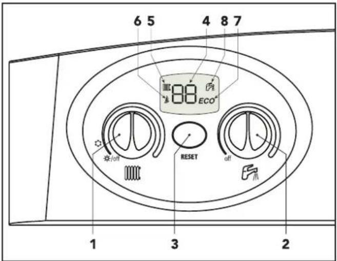
Fig. 1
Information during operation
During normal operation, the boiler diagnostics control sends information on the state of the boiler via the display (Fig.1).
| Display | Type of operation |
 | Boiler off |
 | Boiler on stand-by |
 | Boiler on stand-by / ECO |
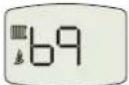 | Heating operation(burner on) |
 | Hot tap water operation(burner on) |
 | Fault codes (See chap. 1.6 or 3.0) |
 | TEST mode operation(burner on) |
1.3 Turning on and off
Ignition
- Open the gas isolation valve on the boiler.
- Purge the air from the pipe ahead of the gas valve.
- Turn on the 3 amp electrical switch or insert the plug to the boiler.
- Turn the heating and hot water knob onto the required temperatures (see par. 1.4).
- The boiler is now ready to function automatically whenever hot water is drawn or both the time clock and room thermostat call for heating.
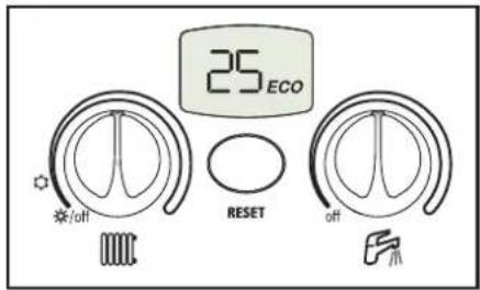
Turning off
Turn the knobs (ref. 1 and 2 Fig. 1) onto minimum.
When the boiler is turned off, the PCB is still powered.
Hot water and heating operation are disabled, the display shows

but the frost protection function stays on


The frost protection will not work if the electricity and/or gas supply to the unit are cut off. To avoid damage caused by freezing during long shutdowns in winter, it is advisable to drain all water from the boiler, the tap water and the system water; or drain off just the tap water and add a suitable antifreeze to the heating system, as prescribed in chap. 2.3.
1.4 Adjustments
Summer/winter Switchover
Depending on the position of the control knobs "1" and "2" it is possible to switch off the boiler unit, switch between summer and winter operation or turn off the domestic hot water.


Switching off the boiler, switching between summer and winter operation and turning off hot tap water has priority over the remote timer control (optional) when this is connected to the boiler.
C.H. temperature setting
To set the system delivery temperature, turn the knob (ref. 1 - Fig. 1).
It can vary from a minimum of 30\ °C to a maximum of 85\ °C ; however, it is advisable not to operate the boiler below 45\ °C . When the knob is turned the display lights up, the radiator symbol flashes and the temperature displayed will be the temperature actually set. On completing this operation, the display will stay on for another 5 seconds and then go back to the actual operating temperature providing there is a demand.display.
Domestic Hot water temperature adjustment
To set the tap water temperature, turn the knob (ref. 2 - Fig. 1).
It can vary from a minimum of 40\ °C to a maximum of 55\ °C . When the knob is turned the display lights up, the tap symbol flashes and the temperature displayed will be the temperature actually set. On completing this operation, the display will stay on for another 5 seconds to then go back to the actual operating temperature providing there is a demand.

If the boiler is connected with the optional remote timer control, the above adjustments (system and hot water temperature) can be made with the remote control.
ECO/COMFORT selection
The unit is equipped with a special internal device that ensures a high hot-water delivery speed and excellent user comfort. When the device is working (COMFORT mode), the water in the boiler is kept at temperature, which means that hot water is available at the boiler outlet as soon as a tap is opened, with no waiting.
The user can turn the device off (ECO mode) by pressing the multi-function button for 2 seconds with the boiler on standby. In ECO mode the display shows the relevant symbol. To turn on COMFORT mode, press the multi-function button again for 2 seconds, the ECO symbol will vanish from the display.
TEST MODE selection

Pressing the multi-function button 3 times in 3 seconds turns on TEST mode (the heating and hot water symbols blink simultaneously - see par. 3.1). If TEST mode is turned on by accident, press the button 3 times in 3 seconds again to exit. (Test time 15 minutes unless cancelled early)
1.5 Maintenance
It is strongly recommended to carry out annual maintenance on the boiler and the heating system. Please refer to the "maintenance" section in this manual.
The casing, the control panel and the aesthetic parts of the boiler can be cleaned using a soft and damp cloth.
Do not use abrasives or solvents.
1.6 Faults
The boiler is equipped with an advanced self-diagnosis system that signals any faults on the display. Some faults (from F1 to F3) cause a boiler shutdown. In this case, operation must be reset manually by pressing the multi-function button (RESET) for 1 second or with the optional remote timer control if one has been installed. Other faults (from F5 to F37) cause temporary shutdowns that are automatically reset as soon as the value causing the fault comes back within the boiler's normal working range.
Listed below are the anomalies that can be caused by simple, user-solvable problems.
If the problem remains after two attempts at resetting, contact your nearest Service Centre.
For other faults, refer to section 3.4 "Troubleshooting".
| Fault CureDisplay code | ||
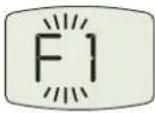 | Boiler shutdown | Make sure that the gas cocks ahead of the boiler and on the meter are open. Check condensate discharge, make sure it is clean and not obstructed.Press the multi-function button (for 1 second) (fig.1)In case of repeated shutdowns, contact the nearest service centre. |
 | Low system pressure | Fill the 'system to 1-1.5 bar cold by means of the 'filling point C.h. (see page 11) |

Before calling a Ferroli service engineer, check that the problem is not due to there being no gas or electricity.
2. INSTALLATION
2.1 General Instructions
This device must only be used for the purpose for which it is specially designed. This unit is designed to heat water to a temperature below boiling point and must be connected to a heating system and/or a water supply system for domestic use, compatible with its performance, characteristics and its heating capacity. Any other use is considered improper.
BOILER INSTALLATION MUST ONLY BE PERFORMED BY QUALIFIED PERSONNEL, IN ACCORDANCE WITH ALL THE INSTRUCTIONS GIVEN IN THIS TECHNICAL MANUAL, THE PROVISIONS OF CURRENT LAW, THE RECOMENDATION OF BS STANDARDS, ANY LOCAL REGULATIONS AND THE RULES OF COMPETENT WORKMANSHIP.
In IE, the installation must be carried out by a Competent Person and installed in accordance with the current edition of I.S. 813 "Domestic Gas Installations", the current Building Regulations and reference should be made to the current ETCI rules for electrical installation.
Incorrect installation can cause damage or physical injury for which the manufacturer declines any responsibility.
This appliance must be installed strictly in accordance with these instructions and regulations:
The Gas Safety Regulations (Installations & Use).
The Local Building Regulations.
The Building Regulations (Part L).
The Buildings Standards (Scotland - Consolidated) Regulations.
British Standards Codes of Practice:
B.S. 5440 Part 1 Flues
B.S. 5440 Part 2 Air supply
B.S. 5449 FORCED CIRCULATION HOT WATER SYSTEMS
B.S. 6798 INSTALLATION OF GAS FIRED HOT WATER BOILERS
B.S. 6891 GAS INSTALLATIONS
B.S. 7671 IEE WIRING REGULATIONS
B.S. 4814 SPECIFICATION FOR EXPANSION VESSELS
B.S. 5482 INSTALLATION OF LPG
B.S. 7593 TREATMENT OF WATER IN DOMESTIC HOT WATER CENTRAL HEATING SYSTEMS
B.S. 5546 INSTALLATION OF HOT WATER SUPPLIES FOR DOMESTIC PURPOSES
B.S. 3632 RESIDENTIAL PARK HOMES
I.S. 813 DOMESTIC GAS INSTALLATIONS (EIRE ONLY)
Local Water Bye Laws
B.S. 5955-8 PLASTIC PIPEWORK INSTALLATION
For Northern Ireland the rules in force apply
2.2 Boiler location
The boilers combustion chamber is sealed off from the installation room. The installation room must be sufficiently well ventilated to prevent any dangerous conditions from forming in the event of even slight gas leakage. This safety standard is required by the EEC Directive no. 90/396 for all gas units, including those with a so-called sealed chamber.
Therefore the place of installation must be free of dust, flammable materials or objects or corrosive gases. The room must be dry and not subject to freezing.
The boiler is design to be installed on a solid wall. The wall fixing must ensure a stable and effective support for the appliance, using the bracket and fixings supplied.
If the unit is enclosed in a cupboard or mounted alongside, there must be space for normal maintenance work. Fig. 2 and tab. 1 give the minimum clearances to leave around the unit.
This appliance does not require compartment ventilation for combustion purposes
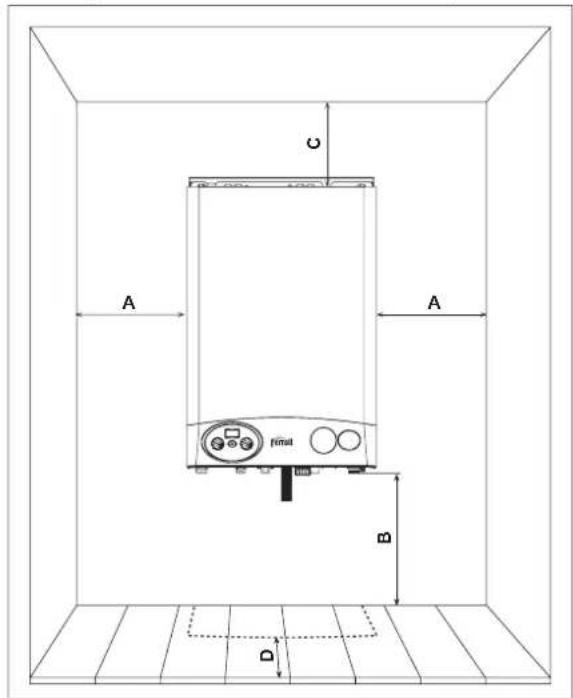
fig. 2
| Table 1 | |
| Minimum | |
| A | 5 cm |
| B | 20 cm |
| C 20 cm | |
| D | 60 cm(via an openable panel) |
Drilling Template
Select suitable mounting position for boiler, using the template mark flue outlet and boiler mounting points. Drill two 10mm holes 70mm deep to accept the wall plugs. Fit standard wall plugs on the left and right side and the special wall plug in the middle (fig. 3). Fix the wall bracket to the wall using standard lock nut (M8) on both sides. Mount the boiler on the wall bracket and fix using the special antitheft nut (M8) as described in the fig. 3. Using a core drill cut a 118mm diameter hole for the flue as detailed on page 17.

Make Up Water
Provision must be made for replacing water lost from the sealed system. Reference should be made to BS6798, for methods of filling and making up sealed systems. There must be no direct connection between the boiler's central heating system and the mains water supply. The use of mains water to charge and pressurise the system directly, is conditional upon the Local Water Byelaws. Again any such connection must be disconnected after use. The temporary filling loop (not supplied) is shown in fig. 5. Ensure the filling point is on the return pipe to the boiler.
Attention - is drawn to the Local Water Byelaws.
Fittings manufactured from duplex (alpha-beta) brass are not acceptable for underground use and certain water undertakings will not accept their use above ground.
Ensure all pipework is adequately supported
![graph TD A["Cold water inlet"] --> B["Hot water"] B --> C["Gas"] C --> D["Filling point C.H."] D --> E["Automatic Bypass"] E --> F["Addition Expansion Vessel C.H. (if required)"] style A fill:#f9f,stroke:#333 style B fill:#ccf,stroke:#333 style C fill:#cfc,stroke:#333 style D fill:#fcc,stroke:#333 s…](/content/2026/05/875162/images/a759bee2f3aa8f968871fd3fcc47c9718eb2045c9b02f38887edbc1745e54f39.jpg)
NOTE: An automatic bypass capable of passing 6 ltrs per minute must be fitted as far as possible from the boiler if thermostatic radiator valves are fitted throughout.
fig. 4
Key

- Filling point C.H. 15mm isolation valve.
- Temporary flexible connection
- Cold water supply 15mm isolation valve
- Double check valve
fig. 5
2.3 Boiler water connections
The heating capacity of the unit should be previously established by calculating the building's heat requirement according to current regulations. For good operation and long life of the boiler, the plumbing system must be well proportioned and always complete with all those accessories that guarantee efficient operation and running, room thermostat, trv's and automatic bypass.
If the delivery and return pipes follow a path where air pockets could form in certain places, it is essential to install air vent valves at these points. Also, install a type "A" drain cock device at the lowest point in the system to allow its complete draining.
The temperature differential between the flow manifold and the return to the boiler should not exceed 20° C.
A minimum flow of 6 litres/min is required through the heat exchanger, it is therefore essential to fit a automatic bypass a min of 3 metres away from the appliance, calibrated on site.

Do not use the water system pipes to earth electrical appliances.
Before installation, carefully flush all the pipes of the heating system to remove residues or impurities that could affect the unit's good working (BS 7593 Building regs Doc L).
Make the connections to the appliance as shown in fig. 6.

Key
1 System flow (22 mm with isolation valve fitted)
2 DHW outlet (15 mm with isolation valve fitted)
3 Gas inlet (22 mm with isolation valve fitted)
4 Cold main inlet (15 mm with isolation valve fitted)
5 System return - 22 mm with isolation valve fitted (c/w filter)
6 Condense outlet
fig. 6
It is essential to install the isolation valves supplied between the boiler and heating system, allowing the boiler to be isolated from the system if necessary.

The safety valve outlet must be connected to a 15 mm pipe to discharge outside the property in the event of over-pressure in the heating circuit. If this is not done, and the drain valve trips and floods the room, the boiler manufacturer is not to be held responsible. The outlet should face back against the outer brickwork or building face to prevent harm or injury from hot water discharging in the evet of an over-pressuried system.
Make the boiler connection in such a way that its internal pipes are free of stress. If a check valve is installed on the tap water circuit (where applicable), it is necessary to mount a safety valve between the boiler and this circuit (check valve minimum 3 metres from boiler).
The connecting kits shown in fig. 7 are supplied as standard.

fig. 7
Water treatment
When treatment is used ferroli limited only recommend the use of proprietary Brand, such as Fernox or Sentinel water treatment products, which must be used in accordance with the manufactures instructions. for further information contact:
| Fernox Manufacturing Co. LTD.Cookson Electronics, Forsyth RoadSheerwater, Woking, Surrey GU21 5RZTel: 0870 8700362 | Sentinel DivisionBetz Dearborn LTDWidnes, Cheshire WA8 8NDTel: 0151 424 5351 |
Note - When the boiler is installed with an existing or new system any unsuitable additives or system debris must be removed by thorough cleansing. All systems should be cleansed according to B.S. 7593.
Note - In hard water areas treatment to prevent lime scale may be necessary.
Note - It is important that the correct concentration of the water treatment product is maintained in accordance with the manufacturers instructions.
2.4 Connection to the gas system
If necessary the local Gas supplier should be consulted, at the installation planning stage, in order to establish the availability of an adequate supply of gas.
An existing service pipe must not be used whitout prior consultation with the local Gas supplier.
A gas meter can only be connected by the Local Gas supplier, or by a Local Gas suppliers Contractor.
Installation pipes should be fitted in accordance with BS6891.
Appliance inlet working pressure must be 20 mbar MINIMUM, for NG and 37 mbar minimum for propane.
Do not use pipes of a smaller size than the combination boiler inlet gas isolation valve (22 mm).
The complete installation must be tested for gas soundness and purged as described in BS6891. All
A pipework must be adequately supported. An isolating gas valve is provided and should be fitted on the boiler gas inlet. Please wait 10 minutes when ligthing from cold before checking the gas rate. Gas pressures should be checked after the boiler has operated for 10 minutes to ensure thermal equilibrium.
2.5 Electrical Connections
The unit must be installed in conformity with current national and local regulations inc 16th Edition & B.S. 7671.
Connection to the electrical supply
The boiler must be connected to a single-phase, 230 Volt-50 Hz electrical supply.
The unit's electrical safety is only guaranteed when correctly connected to an efficient earthing system installed according to current safety standards. Have the efficiency and suitability of the earthing system checked by professionally qualified personnel. The manufacturer is not responsible for any damage caused by failure to earth the system. Also make sure that the electrical system is adequate for the maximum power absorbed by the unit, as specified on the boiler dataplate, in particular ensuring that the cross section of the system's cables is suitable for the power absorbed by the unit.
The boiler is prewired and provided with a cable for connection to the electricity supply. The connections to the supply must be made with a permanent connection and equipped with a double pole switch whose contacts have a minimum opening of at least 3 mm, and fused at max. 3A between the boiler and the line. It is important to respect the polarities (LIVE: brown wire / NEUTRAL: blue wire / EARTH: yellow-green wire) in making connections to the electrical supply.
The user must never change the boilers power cable. If the cable gets damaged, switch off the unit and have it changed only by professionally qualified personnel. If changing the electric power cable, use solely "HAR H05 VV-F" 3x0.75 mm 2 cable with a maximum outside diameter of 8 mm.
5 Core cable must not be used to replace the existing 3 core.
Access to the electrical terminal block
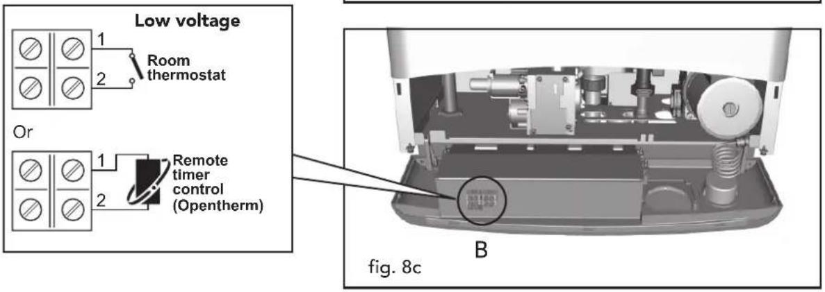
To access the terminal block where the room thermostat (low voltage) or the remote timer control is to be connected, carry out the following operations:
1 Unscrew the two screws "A" (Fig. 8a)
2 Lower the instrument panel (Fig. 8b)
3 Turn the instrument panel (Fig. 8c)
You can now access the terminal block "B"
(Fig. 8c)


2.6 Flue system
The unit is "type C" with a sealed chamber and forced draught, the air inlet and flue outlet must be connected to one of the following flue systems. With the aid of the tables and methods of calculation indicated, before commencing installation, it is first necessary to check that the flue system does not exceed the maximum permissible length. The current standards and local regulations must be observed.

It should be noted that only Ferroli flue system and accessories should be used on this appliance, as per BS 5440 2000 and C.E. test certification.
Restrictor
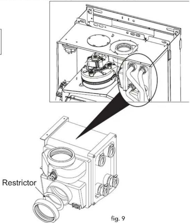
This appliance is factory fitted with the correct restrictor for use with a standard 100mm concentric flue terminal of less than 1 mtr. For different flueing applications choose the correct size restrictor from the tables below. To change the restrictor please follow the instructions below, shown in figure 9.
Determine the correct size of flue restrictor required. Before inserting the flue gas duct in the boiler, check that the restrictor fitted is correct and that it is correctly positioned (see fig. 9).
N.B.: the diameter of the hole is stamped on the restrictor
Choice of restrictor:
- With 2 pipe system:
- Calculate the total flow resistance of the air and flue pipes in metres.
- utilise the table shown below to choose the more suitable restrictor for the flow resistance calculated
| RESTRICTOR FOR TWO PIPE SYSTEM | ||
| Total flow resistance of flue system | Use restrictor size | |
| minimum m | maximum mm | |
| 0 m 32 m | 50 | |
| 32 m 48 m | No restrictor | |
- With concentric systems:
- Choose correct restrictor from table below.
| RESTRICTOR FOR CONCENTRIC SYSTEM | ||
| Flue length up to: | Use restrictor size | |
| Concentric 60 / 100 | 1 bend + 1 metre 50 | mm |
| 1 bend + 3 metres No restrictor | ||
| Concentric 80 / 125 | 1 bend + 5 metres 50 | mm |
| 1 bend + 12 metres | No restrictor | |
Connection with concentric flue system
The unit can be connected to a concentric air/flue duct with a wall or rooftop outlet as shown on the following drawings. Numerous accessories are available on request to meet the various installation requirements. Please refer to our "flue manual" or the price list.
Horizontal concentric flue installation

L = S + D + 163,5 mm
Horizontal flue installation
- Define the suitable position for installing the boiler (see 2.2 boiler location)
- When installing a horizontal flue kit, please ensure a 3mm per metre fall back to the appliance is incorporated
- Make a hole of diameter 10 - 20 mm greater than the nominal diameter of the concentric pipe used.
-
If necessary, cut the end pipe to size, ensuring that the external pipe protrudes from the wall by between 10 and 60 mm (Fig. 10a and 10b). Remove the cutting burrs and lubricate the seals with a suitable silicone based grease.
-
Connect the flue to the boiler, positioning the seals correctly. Seal the flue into the wall with silicone or sand & cement a and cover with wall seals provided.

Flue seals should be lubricated with a silicone type grease to prevent damage (grease not supplied)
Vertical Outlet
The total length in equivalent metres of the concentric flue must not exceed the maximum lengths stated in the following table, note that each bend gives rise to the stated reduction. For example, a duct = 60/100 composed of 1 bend of 90° + 1 horizontal metre + 2 bends of 45° + 1 horizontal metre has a total equivalent length of 4 metres.
| Table 2a | ||
| ∅ mm60/100 | ∅ mm80/125 | |
| Maximum permissible duct length (Horizontal) | 3 m 12 m | |
| Maximum permissible duct length (vertical) | 4 m 12 m | |
| Table 2b | |
| Reduction factors for bends | |
| Concentric bend at 90° - ∅ 60/100 mm | 1 m |
| Concentric bend at 45° - ∅ 60/100 mm | 0.5 m |
| Concentric bend at 90° - ∅ 80/125 mm | 0.5 m |
| Concentric bend at 45° - ∅ 80/125 mm | 0.25 m |

fig. 10c
Connection with 80 mm pipe system
The unit can be connected to a system of separate air/flue pipes for a horizontal or vertical outlet as shown on the fig. 11-12. Numerous accessories are available on request to meet the various installation requirements.
Please refer to the flue manual catalogue or the price list for additional components.
To check you do not exceed the maximum permissible flue length, it is necessary to make a simple calculation before installation:
- For each component, tables 4 - 5 (page 20) provide an "equivalent loss in metres", depending on the position of installation of the component (with air intake or flue extraction, vertical or horizontal).
The loss is called "equivalent length" since it is compared to the loss of one metre of flue (defined as equal to 1). For example, a bend at 90° of 80 in flue run has an equivalent loss of 2.5 linear metres, i.e. it has a loss equal to that of 2.5 metres of flue length. - After designing the layout of the system, add up the losses in equivalent metres, depending on the installation position, of all the components and accessories in the system.
- Check that the total calculated loss is less than or equal to 48 equivalent metres, i.e. the maximum permissible for this model of boiler.

For complete flue options please contact FERROLI or check our comprehensive flue manual.
| Table 3 | |||
| Ref. | N° Pieces | Description | Equivalent loss |
| 1 | 16 | Vertical flue pipe ∅80 | 25,6 m |
| 2 | 10 | Vertical air pipe ∅80 | 10,0 m |
| 3 | 1 | Vertical flue terminal | 12,0 m |
| 4 | 1 | Two pipe adaption kit (1KWMR54A) | 0,0 m |
| Total 47,6 m | |||


fig. 12
Table of flue and accessories
Table 4 Table 5
| Accessories ∅ 80 Accessories ∅ | Equivalent losses in metres (linear) | ||||
| Vertical | Horizontal | Vertical | Horizontal | ||
| Description | |||||
| Pipe ∅ 80 male-female |  KWMA83W · 1,00 m KWMA83W · 1,00 m | 1 | 1 | 1 | . |
| Bend 45° ∅ 80 mm male - female |  KWMA65W KWMA65W | 1.2 1.8 | |||
| Bend 90° ∅ 80 mm male - female |  KWMA01W KWMA01W | 1.5 2.0 | |||
| Equivalent losses in metres (linear) | |||||
| Air Flue | |||||
| Description | Vertical | Horizontal | Vertical | Horizontal | |
| Horizontal flue terminal | [4808] KWMA86A | 5 | |||
| 2 Horizontal air terminal | [499] KWMA85A | 2 | |||
| Vertical flue terminal | [52W4] KWMA84U | 12 | |||
The stated loss values refer to genuine Ferroli flue accessories.
Terminal Position

Statutory minimum distances for terminal siting

A - minimum distance 600mm - may be a nuisance if it 'wets' opposite boundary, crosses main pathway or condensate can drip on pathway.
B - minimum distance 600mm - may be a nuisance as plume could obscure window.
C - minimum distance 600mm - may be a nuisance if plumecrosses door.
The plume should not cross:
- a frequently used access route;
- any frequently used area (such as a patio or car parking space);
• a neighbouring dwelling.
Nor should it be directed towards a window or door, or be sited close to a facing wali or other surface.
There are also other aspects to consider when planning the flue terminal position.
- A free passage of air is needed at all times to aid plume dispersal - which may be difficult in sheltered locations.
- In cold weather, the condensate could cause a safety hazard if it freezes on pathways, or if it results in frost damage to surfaces.
- The plume could trigger infra-red security lighting if sited in the wrong place.
- Ensure terminals do not obscure security camera field of vision.
- The terminal guards must be able to resist corrosive properties of the condensate.
Minimum Dimensions of Flue Terminal Positions
| A | Directly below an opening, air brick, opening windows, etc. | 300mm |
| B | Above an opening, air brick, opening windows, etc. | 300mm |
| C | Horizontally to an opening, air brick, opening windows, etc. | 300mm |
| D | Below gutters, soil pipes or drain pipes | 75mm |
| E | Below eaves | 200mm |
| F | Below balconies or car port roof | 200mm |
| G | From a vertical drain pipe or soil pipe | 150mm |
| H | From an internal or external corner | 100mm |
| I | Above ground roof or balcony level | 300mm |
| J | From a surface facing the terminal | 600mm |
| K | From a terminal facing the terminal | 1200mm |
| L | From an opening in the car port (e.g. door, window) into the dwelling | 1200mm |
| M | Vertically from a terminal on the same wall | 1500mm |
| N | Horizontally from a terminal on the same wall | 300mm |
| O | From the wall on which the terminal is mounted | N/A |
| P | From a vertical structure on the roof | 150mm |
| Q | Above intersection with roof | 300mm |
NOTE
N/A = Not applicable
In addition, the terminal must not be nearer than 300mm to an opening in the building fabric formed for the purpose of accommodating a built-in element such as a window frame.
Condensing Terminal Positions: If the flue is to be terminated at low level, then the potential effect of the plume must be considered.
The plume should not be directed:
- across a frequently used access route
- towards a window or door
- across a neighbouring property
Connection to collective flues or single flues with natural draught
If you are then going to connect the DOMIcompact F 30 B boiler to a collective flue or a single flue with natural draught, the flue must be expressly designed by professionally qualified technical personnel in conformity with the standards and rules in force.
In particular, flues must have the following characteristics:
- Be sized according to the method of calculation stated in the standard
- Be airtight to the products of combustion, resistant to the fumes and heat and waterproof for the condensate
- Have a circular or square cross-section (some hydraulically equivalent sections are permissible), with a vertical progression and with no restrictions
- Have the ducts conveying the hot fumes adequately distanced or isolated from combustible materials
- Be connected to just one unit per floor, for at most 6 units in all (8 if there is a compensation duct or opening)
- Have no mechanical suction devices in the main ducts
- Be at a lower pressure, all along their length, under conditions of stationary operation
- Have at their base a collection chamber for solid materials or condensation of at least 0.5 m, equipped with a metal door with an airtight closure.
2.7 Condensate outlet connection


fig. 13
The boiler is equipped with an internal siphon-trap to drain off the condensate. Fit the inspection bowl A and the hose B, pushing it on for approximately 3 cm.

Fill the siphon-trap with approximately 0.5 l. of water and connect the hose to the waste system or soakaway
Condensate discharge
Where possible the condensate should discharge into an internal soil pipe or waste system. The minimum pipe diameter required is 22 mm, a trap has already been fitted to the appliance with a flexible hose to facilitate the connection to the condensate discharge pipe.
The pipe should be a solvent weld plastic, not copper, as the condensate has a ph value of 4 (slightly acidic).
Where it is not possible to terminate internally, the condensate discharge pipe may be run outside (see below drawing).
Any external run is subject to freezing, in severe weather conditions. To avoid this the pipework should be installed to dispose of the condensate quickly, with as much as possible run internally, before passing through the wall.
Pipework external to the building should be increased in diameter to 32 or 40 mm solvent weld. It should be run to a external drain or soakaway, with a maximum length of 3 metres.
If a soakaway (condensate absorption point) is used, it should be constructed as shown below.

The gradient of the discharge pipe should be 2.5° (45 mm/m) minimum.
fig. 14
3. SERVICE AND MAINTENANCE
3.1 Adjustments
All adjustment and conversion operations must be carried out by a Qualified and trained engineer such as a Ferroli service engineer.
FERROLI S.p.A. declines any responsibility for damage or physical injury caused by unqualified and unauthorised persons tampering with the device.
Gas supply conversion
The unit can function with either Natural Gas or LPG and is factory-set for use with one of the two gases, as clearly shown on the packing and on the unit's dataplate. Whenever a different gas to that for which the unit is preset has to be used, a conversion kit will be required, proceeding as follows:
- Replace the injectors at the main burner, by inserting the injectors specified in the technical data table in chap. 4, according to the type of gas used
- Adjust the burner minimum and maximum pressures (ref. relevant paragraph), setting the values given in the technical data chart for the type of gas used.
-
How to adjust the parameter for the specific type of gas to be used:
-
turn the boiler onto standby
- press the RESET button for 10 seconds
- P1 will appear on the display
- press the RESET button for 5 seconds
- turn the hot water knob (ref. 2 - fig 1) onto "0" (for Natural Gas operation) or onto "1" (for LPG operation)
- press the RESET button for 5 seconds
- P2 will appear on the display
- turn the heating knob (ref. 1 - fig 1) onto minimum and then onto maximum
- the boiler will go back onto standby
-
turn the heating & hot water knobs onto the set temperatures.
-
Attach the sticker contained in the conversion kit, near the dataplate as proof of the conversion.
Turning on TEST mode
To turn on TEST mode, press the multi-function button 3 times in 3 seconds.
The display will show the radiator and hot water symbols flashing, the current heating power, the ECO symbol (if ECONOMY mode is on) and the flame symbol.
To quit TEST mode, press the multi-function button 3 times in 3 seconds.
TEST mode turns off automatically after 15 minutes.

Adjusting burner pressure
Since this unit has flame modulation, there are two fixed pressure settings: the minimum and maximum, which must be as stated in the technical data chart according to the type of gas.
- Connect a suitable pressure gauge to pressure point "B" downstream from the gas valve having loosened it first.
- Disconnect the pressure compensation tube "H".
• Take off the protective cap "D". - Run the boiler in TEST mode (press the multi-function button 3 times in 3 seconds): - TEST mode on: turn the heating knob (ref. 1 - fig 1) onto maximum.
- Adjust the maximum pressure with the screw "G", clockwise to increase it and anticlockwise to decrease it.
- Disconnect one of the two electrical connectors from the moduleg "C" on the gas valve.
- Adjust the minimum pressure with the screw "E", clockwise to decrease it and anticlockwise to increase it.
- Reconnect the electrical connector disconnected from the modureg on the gas valve.
- Check that the maximum pressure has not changed.
- Reconnect the pressure compensation tube "H".
- Put the protective cap "D" back on.
- To end TEST mode, repeat the sequence for turning it on or wait 15 minutes.


fig. 15
Key
B Pressure point
C Modureg electrical connection
D Protective cap
E Minimum pressure adjustment
G Maximum pressure adjustment

Having disturbed test point 'B' when checking or adjusting the gas pressures, it is considered mandatory to check for gas leaks using a suitable leak detection fluid or sniffer at that connection.
Adjusting the maximum heating output
To adjust the heating power, set the boiler on TEST operation (see par. 3.1). Turn the heating temperature control knob (ref. 1 - Fig. 1) clockwise to increase the power or anticlockwise to decrease it (see pressure/power diagram Fig. 21). The display shows the power setting from 0 to 99%. Exit TEST operation (see par. 3.1). The maximum heating power will remain as set during the TEST mode. (100% output shown as 99% due to the display only being 2 digits).
Ignition power adjustment
To adjust the ignition power, set the boiler on TEST operation (see par. 3.1).
Turn the hot water temperature control knob (ref. 3 - Fig. 1) clockwise to increase the power or anticlockwise to decrease it (see pressure/power diagram Fig. 21). The display shows the power setting from 0 to 60%. Exit TEST operation (see par. 3.1). The ignition power will remain as set during the TEST mode.
NOTE Recommended ignition pressure for standard 100mm concentric flueing is 30%.
3.2 Initial start-up

Commissioning must be performed by Qualified Personnel only!.
Checks to be made at initial start up, and after all maintenance operations that involved disconnecting from the system or an intervention of a safety device.
Before lighting the boiler:
- Open any isolation valves between the boiler and the systems.
- Check the soundness of the gas system, proceeding with caution and using a suitable leak detection fluid to detect any leaks in connections.
- Fill the water system and make sure that all air contained in the boiler and the system has been vented by opening the air vent valve on the boiler and any vent valves on the system.
- Make sure there are no water leaks in the system, hot water circuits, connections or boiler.
- Make sure the electrical supply is properly connected.
- Make sure that the unit is connected to a good earthing system.
- Make sure that there is sufficient gas available to produce safe combustion. (min inlet working pressure = 20mbar)
- Make sure there are no flammable liquids or materials in the immediate vicinity of the boiler.
Lighting the boiler
- Open the gas isolation valve on the boiler.
- Purge the air from the gas pipe work to the boiler.
- Switch on the electrical supply to the boiler.
- Turn knob "1" (Fig. 1) onto Winter in correspondence with a value greater than 50°C and the room thermostat knob, if applicable, onto the desired temperature setting. At this point, the burner will light and the boiler begins to function automatically, controlled by its software and safety devices.
If, after correctly carrying out the lighting procedure, the burners do not light and fault F1 is generated, press the RESET button for 1 second and release it. The software will repeat the ignition cycle in the next 30 seconds. If the burners do not light after the second attempt, consult the "Troubleshooting" paragraph.
In case of an electrical power failure while the boiler is working, the burners will go out and re-ignite automatically when power is restored.


Checks during operation
- Check the soundness of the gas circuit and water systems.
- Check the efficiency of the flue and air-flue ducts while the boiler is working.
- Check that the water is circulating properly between the boiler and the systems.
- Make sure that the gas valve modulates correctly in both the heating and hot water production modes.
- Check the proper ignition of the boiler by performing various tests, turning it on and off with the room thermostat or remote control.
- Make sure that the gas consumption indicated on the meter corresponds to that given in the technical data table in chap. 4. (Input rating)
- Check there is the right flow rate of hot water with the Δt stated in the chart: The measurement should be made with specific instruments and as close as possible to the boiler, also considering the heat lost from the pipework.
- Make sure that with no call for heating the burner correctly ignites on opening a hot water tap. Check that during heating operation, on opening a hot water tap, the heating pump stops and there is a regular production of hot water.
- Check the parameters are programmed correctly and perform any required customization (power, temperatures, etc.)
Turning off
Turn the knobs (ref. 1 and 2 Fig. 1) onto minimum.
When the boiler is turned off, the printed circuit board is still powered.
Hot water and heating operation are disabled, the display shows but the frost protection mode remains active.

The frost protection system will not work if the electricity and/or gas supply to the unit are cut off.
To avoid damage caused by freezing during long shutdowns in winter, it is advisable to drain all water from the boiler, the tap water and the system water; or drain off just the tap water and add a suitable antifreeze to the heating system, as prescribed in chap. 2.3.
3.3 Maintenance

The following operations must only be carried out by suitably trained and qualified personnel, such as Ferroli service engineers.
Seasonal inspection of the boiler and flue
It is advisable to carry out the following checks at least once a year:
- The control and safety devices (gas valve, flow meter, thermostats, etc.) must function correctly.
- The air-flue terminal and ducts must be free of obstructions and leaks.
- The gas and water systems must be airtight.
- The burner and exchanger must be clean. Follow the instructions in the next paragraph.
- The electrode must be free of debris and properly positioned.
- The water pressure in the cold water system must be about 1 bar; otherwise, bring it to that value.
- The expansion tank must be filled with air at 1 bar.
- The gas flow and pressure must correspond to that given in the respective tables.
- The circulation pump must be manually spun, vented and not be restricted.
- The condensate discharge must be clean, free of obstructions and leaks and the sediment bowl cleaned out.
Opening the casing
To open the boiler casing:
1 Unscrew the two screws A
2 Lower the instrument panel
3 Drop down the instrument panel
4 Fully unscrew the two screws B
5 Raise and remove the casing C

Before carrying out any operation inside the boiler, disconnect the electrical power supply and isolate the gas supply.

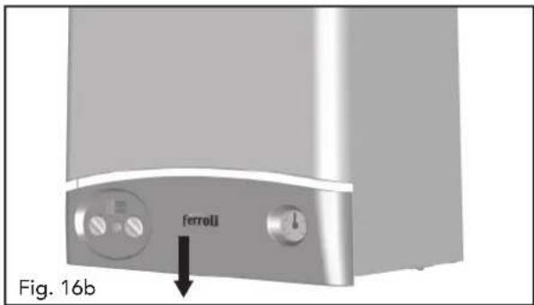
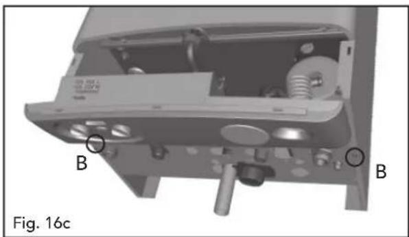
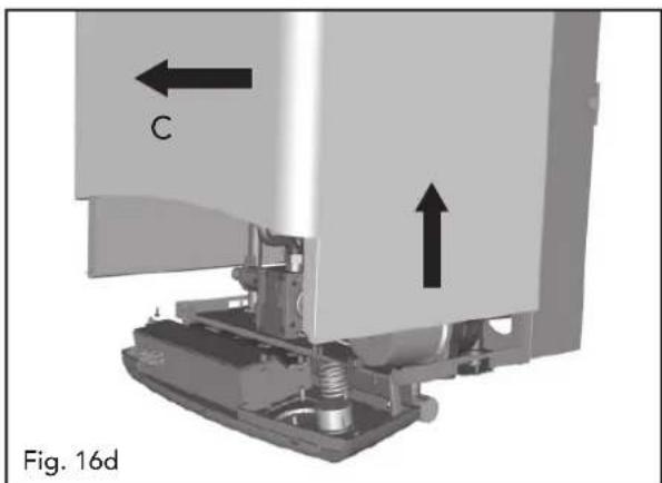
Cleaning the boiler and burner
The body and burner must not be cleaned with chemical products or wire brushes. Special care must be taken over all the sealing systems pertaining to the sealed chamber (gaskets, cable clamps, etc.). After performing all these operations, check and carry out all the phases of ignition and thermostat operation, the gas valve and circulation pump.

After these checks, make sure there are no gas leaks.
Combustion analyser testing
It is possible to analyse the combustion through the air and flue sampling points shown in fig. 17. To make the measurement, it is necessary to:
1) Open the flue sampling point
2) Insert the probe;
3) Turn on the hot water tap;
4) Turn the domestic hot water stat to maximum;
5) Allow the boiler to reach thermal equilibrium (10 - 15 min.);
6) Wait 10 minutes for the boiler to stabilize
7) Take the measurement.

fig. 17
3.4 Troubleshooting
Fault Diagnosis
The boiler is equipped with an advanced self-diagnosis system. In the event of trouble with the boiler, the display will show the relevant code.
There are faults that cause shutdown (faults from F1 to F3): in order to restore operation it requires the operator to press RESET for 1 second (ref. 2 - Fig. 1) or RESET on the optional remote timer control if this is installed; if the boiler fails to start, it is necessary to resolve the fault indicated on the display.
Other faults (from F5 to F37) cause temporary shutdowns that are automatically reset as soon as the value comes back within the boiler's normal working range.
| Fault | Display code | Possible cause | Cure |
| No burner ignition | F1 | · No gas· Detection or ignition electrode fault· Defective gas valve· Ignition power too low· Condensate discharge full or dirty | · Check the regular gas flow to the boiler and the air has been eliminated from the pipes.· Check the wiring of the electrode and that it is correctly positioned and free of any deposits· Check and change the gas valve· Adjust the ignition power· Verify and clean condensate discharge |
| Flame present with burner off signal | F2 | · Electrode fault· Card trouble | · Check the ionizing electrode wiring· Check the card |
| Safety thermostat trips · Heating sensor damaged | F3 | · No water circulation in the system· Air in the system | · Check the correct positioning and operation of the heating sensor· Check the circulator· Vent the system |
| Air pressure switch (fails to close the contacts within 60 sec. of turning on the fan) | F5 | · Air pressure switch contact open· Incorrect wiring to the air pressure switch· Wrong diaphragm· Flue not correctly sized or obstructed | · Heck the wiringoCheck the fan· Check the pressure switch· Change the diaphragm |
| Delivery sensor fault · Sensor damaged | F7 | · Wiring shorted· Wiring broken | · Check the wiring or change the sensor |
| Tap water sensor fault · Sensor damaged | F9 | · Wiring shorted· Wiring broken | · Check the wiring or change the sensor |
| Low system pressure · System empty | F37 | · Water pressure switch not connected or damaged | · Fill the system· Check the sensor |
4 TECHNICAL CHARACTERISTICS AND DATA
4.1 Dimensions and connections
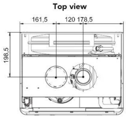


Key
1 Heating system flow ∅ 3/4" (22mm with isolation valve fitted)
2 Hot water outlet ∅ 1/2" (15mm with isolation valve fitted)
3 Gas inlet 1/2" (22mm with isolation valve fitted)
4 Tap water inlet ∅ 1/2" (15mm with isolation valve fitted)
5 Heating system return ∅ 3/4"
6 Condense outlet
Fig. 18
Bottom view
4.2 General view and main components
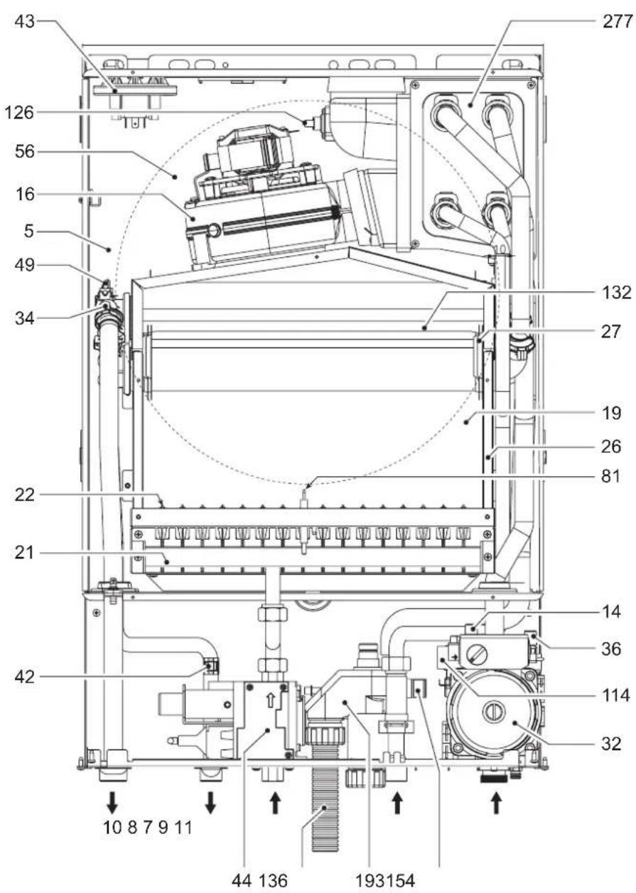
fig. 19
Key
5 Combustion chamber
7 Gas inlet
8 DHW outlet
9 Cold water inlet
10 CH flow
11 CH return
14 Safety valve
16 Fan
19 Combustion chamber
21 Gas injector
22 Burner assembly
26 Combustion chamber insulation
27 Copper heat exchanger for c.h. + d.h.w.
32 Heating pump
36 Automatic air vent
34 Heating flow sensor
42 D.h.w. temperature sensor
43 Air pressure switch
44 Gas valve
49 Safety thermostat
56 Expansion vessel
81 Spark electrode
114 Water pressure switch
126 Flue gas safety thermostat
132 Flue gas deflector
136 Flow switch
154 Condense outlet
193 Condensate Siphon
277 Secondary heat exchanger
4.3 Hydraulic diagram
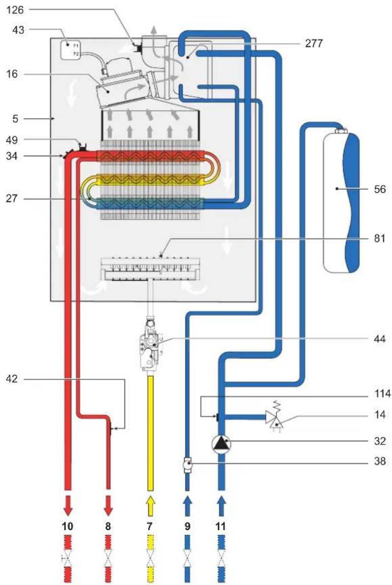
Fig. 20
KEY
5 Room Sealed Compartment
7 Inlet - Gas
8 Outlet - DHW
9 Inlet - Cold Water
10 Flow - CH
11 Return - CH
14 Safety Valve
16 Fan Assembly
27 Heat Exchanger
32 Pump Assembly
34 Sensor - Flow
38 Flow switch
42 Sensor - DHW
43 Air Pressure Switch
44 Gas Valve
49 Thermostat - Safety
56 Expansion Vessel
81 Electrode - Ignition
114 Sensor - Low Water Pressure
126 Thermostat - Flue
277 Heat Exchanger - Secondary
4.4 Technical data table
Table 10
| Powers | Pmax | Pmin | |
| Hi Heating power | kW | 31,1 | 14,1 |
| Useful Heating Power 80°C - 60°C | kW | 30,0 | 12,9 |
| Useful Heating Power 50°C - 30°C | kW | 31,7 | 13,4 |
| Gas supply | |||
| Natural Gas main injectors (G20) | mm | 16 x 1,30 | |
| Natural Gas supply pressure (G20) | mbar | 20,0 | |
| Pressure at Natural Gas burner (G20) | mbar | 10,0 | 2,5 |
| Natural Gas delivery (G20) | nm 3 /h | 3,29 | 1,49 |
| LPG main injectors (G31) | mm | 16 x 0,75 | |
| LPG supply pressure (G31) | mbar | 37,0 | |
| Pressure at LPG burner (G31) | mbar | 35,0 | 7,5 |
| LPG delivery (G31) | kg/h | 2,43 | 1,1 |
| Efficiency | |||
| Seasonal Efficiency (SEDBUK) | Natural gas | 87,7 % | |
| LPG | 88,7 % | ||
| Heating | |||
| Heating temperature adjustment range | °C | 30 - 85 | |
| Maximum working temperature in heating | °C | 90 | |
| Maximum working pressure in heating bar | 3 | ||
| Minimum working pressure in heating bar | 0.8 | ||
| Expansion vessel capacity litres | 10 | ||
| Expansion vessel pre-filling pressure bar | 1 | ||
| Total boiler water content litres | 2,3 | ||
| Hot water | |||
| Hot tap water supply Δt 25°C | l/min | 17,2 | |
| Hot tap water supply Δt 30°C | l/min | 14,3 | |
| Hot tap water supply Δt 35°C | l/min | 12,3 | |
| Tap water temperature adjustment range | °C | 40 - 55 | |
| Maximum working pressure in hot water production bar | 9 | ||
| Minimum working pressure in hot water production bar | 0.25 | ||
| Dimensions, weights connections | |||
| Height mm | 681 | ||
| Width mm | 460 | ||
| Depth mm | 365 | ||
| Weight with packing kg | 44 | ||
| Gas system connection mm | 1/2" | ||
| Heating system connections mm | 3/4" | ||
| Hot water circuit connections mm | 1/2" | ||
| Maximum length of separate flues D=80*(*Measurement given in equivalent linear metres – cfr FERROLI calculation system) | mq | 48 | |
| Electrical power supply | |||
| Max electrical power used | W | 170 | |
| Protection level | IP | X5D | |
4.5 Diagrams
Head available for the system
![| Q [l/h] | Pump Speed 1 | Pump Speed 2 | Pump Speed 3 | | ------- | ------------ | ------------ | ------------ | | 0 | 3 | 5 | 6 | | 1000 | 2 | 4 | 5 | | 2000 | 1 | 3 | 4 | | 3000 | 0.5 | 2 | 3 | | 4000 | 0.2 | 1 | 2 | | 5000 | 0.1 | 0.5 | 1 | | 6000 | 0.05 | 0.2 | 0.5 | | 7000 | 0.02 | 0.1 | 0.2 |…](/content/2026/05/875162/images/560ae45271dbc760772ae29982fc496b1854f25129ba5e201cd955d7a994e06e.jpg)
Fig. 21
4.6 Time Clock
A 24 hour time clock is fitted to the boiler to control the central heating, this will come into operation when the selector switch "F" is turned to the position marked "AUTO".

A Slide switch: set clock - auto - set programme
B Display. Symbol in Display = Timer ON
P Select programme ON/OFF 1.....8
D Push buttons Time + Time -
E Override: Boiler will switch ON if it is OFF; and OFF if it is ON
F I=Heating continuous - AUTO=Heating timed - O=Heating disabled
R Reset (with pencil) only with switch A in set clock position
To set time of day
- Slide switch (A) to left position
- Using button + and - adjust until the correct time is shown on display (B).
Pre Set Programmes. The timer is pre programmed with 3 ON and 3 OFF times.
| 6:30 - 8:3012:00 - 12:0016:30 - 22:30 | If these are suitable no programming is required and the slide switch (A) can be moved to the Auto position and the central heating will be ON for these periods.(12:00 - 12:00 will not switch on the boiler) |
To Set Own ON and OFF times. Symbol in Display = ON time
- Slide switch (A) to right position (P)
Display
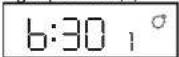
- Press button (P)
Display

- Press button (P)
Display

- Press button (P)
Display
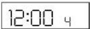
- Press button (P)
Display
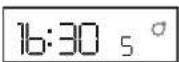
- Press button (P)
Display

- The timer can be programmed with up to 8 ON and 8 OFF times by repeating the above procedure.
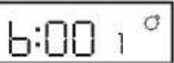
1.1 Use buttons + and - to set 1st ON time eg. 6:00
Display
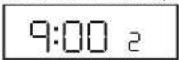
2.1 Use buttons + and - to set OFF time, eg. 9:00
Display
3.1 Use button + and - to set 2nd ON time, eg. 12:30
Display

4.1 Use button + and - to set 2nd OFF time eg. 14:00
Display

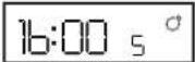
5.1 Use button + and - to set 3rd ON time, eg. 16:00
Display
6.1 Use button + and - to set 3rd OFF time eg. 23:30
Display

- On completion of programming slide switch (A) to Auto position, the time of day will be displayed and the central heating will switch ON and OFF according to the programme set.
Over ride
By pressing the over ride button (E) the timer programme is over ridden ie, if programme is in OFF time it will come ON and if in ON time will go OFF.
The timer will revert back to it set programme on reaching the next ON or OFF time.
When the programme is on over ride the sign will be shown in the display window (B).
Reset Button
By the use of a pencil the reset button can be pushed (R). This will clear all programmes apart from those factory pre set.
Reset is only possible with switch (A) in set Clock position!
4.7 Wiring diagram
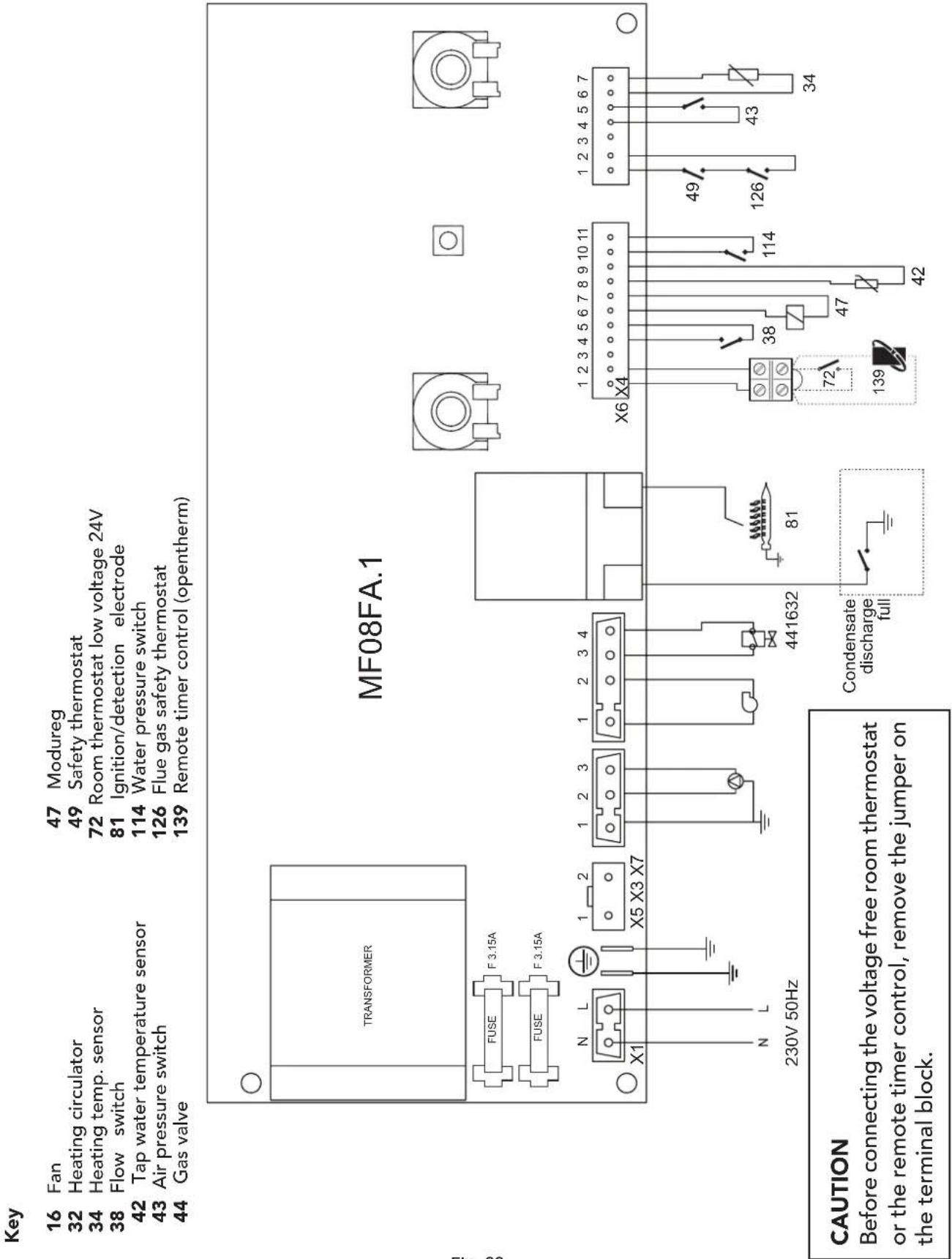
Fig. 22
47 Modureg
49 Safety thermostat
72 Room thermostat low voltage 24V
81 Ignition/detection electrode
114 Water pressure switch
126 Flue gas safety thermostat
139 Remote timer control (opentherm
47 Modureg
49 Safety thermostat
72 Room thermostat low voltage 24V
81 Ignition/detection electrode
114 Water pressure switch
126 Flue gas safety thermostat
139 Remote timer control (opentherm
47 Modureg
49 Safety thermostat
72 Room thermostat low voltage 24V
81 Ignition/detection electrode
114 Water pressure switch
126 Flue gas safety thermostat
139 Remote timer control (opentherm
47 Modureg
49 Safety thermostat
72 Room thermostat low voltage 24V
81 Ignition/detection electrode
114 Water pressure switch
126 Flue gas safety thermostat
139 Remote timer control (opentherm
47 Modureg
49 Safety thermostat
72 Room thermostat low voltage 24V
81 Ignition/detection electrode
114 Water pressure switch
126 Flue gas safety thermostat
139 Remote timer control (opentherm
47 Modureg
49 Safety thermostat
72 Room thermostat low voltage 24V
81 Ignition/detection electrode
114 Water pressure switch
126 Flue gas safety thermostat
139 Remote timer control (opentherm
47 Modureg
49 Safety thermostat
72 Room thermostat low voltage 24V
81 Ignition/detection electrode
114 Water pressure switch
126 Flue gas safety thermostat
139 Remote timer control (opentherm
47 Modureg
49 Safety thermostat
72 Room thermostat low voltage 24V
81 Ignition/detection electrode
114 Water pressure switch
126 Flue gas safety thermostat
139 Remote timer control (opentherm
47 Modureg
49 Safety thermostat
72 Room thermostat low voltage 24V
81 Ignition/detection electrode
114 Water pressure switch
126 Flue gas safety thermostat
139 Remote timer control (opentherm
47 Modureg
49 Safety thermostat
72 Room thermostat low voltage 24V
81 Ignition/detection electrode
114 Water pressure switch
126 Flue gas safety thermostat
139 Remote timer control (opentherm
47 Modureg
49 Safety thermostat
72 Room thermostat low voltage 24V
81 Ignition/detection electrode
114 Water pressure switch
126 Flue gas safety thermostat
139 Remote timer control (opentherm
47 Modureg
49 Safety thermostat
72 Room thermostat low voltage 24V
81 Ignition/detection electrode
114 Water pressure switch
126 Flue gas safety thermostat
139 Remote timer control (opentherm
47 Modureg
49 Safety thermostat
72 Room thermostat low voltage 24V
81 Ignition/detection electrode
114 Water pressure switch
126 Flue gas safety thermostat
139 Remote timer control (opentherm
47 Modureg
49 Safety thermostat
72 Room thermostat low voltage 24V
81 Ignition/detection electrode
114 Water pressure switch
126 Flue gas safety thermostat
139 Remote timer control (opentherm
47 Modureg
49 Safety thermostat
72 Room thermostat low voltage 24V
81 Ignition/detection electrode
114 Water pressure switch
126 Flue gas safety thermostat
139 Remote timer control (opentherm)
47 Modureg
49 Safety thermostat
72 Room thermostat low voltage
81 Ignition/detection electrode
114 Water pressure switch
126 Flue gas safety thermostat
139 Remote timer control (opentherm)
47 Modureg
49 Safety thermostat
72 Room thermostat low voltage
81 Ignition/detection electrode
114 Water pressure switch
126 Flue gas safety thermostat
139 Remote timer control (opentherm)
47 Modureg
49 Safety thermostat
72 Room thermostat low voltage 81 Ignition/detection electrode
114 Water pressure switch
126 Flue gas safety thermostat
139 Remote timer control (opentherm)
47 Modureg
49 Safety thermostat
72 Room thermostat low voltage
81 Ignition/detection electrode
114 Water pressure switch
126 Flue gas safety thermostat
139 Remote timer control (opentherm)
47 Modureg
49 Safety thermostat
72 Room thermostat low voltage 81 Ignition/detection electrode
temperature sensor 114 Water pressure switch
Air pressure switch 126 Flue gas safety thermostat
139 Remote timer control (opentherm)
47 Modureg
47 Modureg
49 Safety thermostat
. sensor 72 Room thermostat low voltage
81 Ignition/detection electrode
temperature sensor 114 Water pressure switch
Air pressure switch 126 Flue gas safety thermostat
139 Remote timer control (opentherm)
GAS BOILER COMMISSIONING CHECKLIST
BOILER SERIAL No.
NOTIFICATION No.
CONTROLS To comply with the Building Regulations, each section must have a tick in one or other of the boxes
| TIME & TEMPERATURE CONTROL TO HEATING | ROOM T/STAT & PROGRAMMER/TIMER | □ | PROGRAMMABLE ROOMSTAT | □ |
| TIME & TEMPERATURE CONTROL TO HOT WATER CYLINDER T/STAT & PROGRAMMER/TIMER | □ | COMBI BOILER | □ | |
| HEATING ZONE VALVES FITTED NOT REQUIRED | □ | □ | ||
| HOT WATER ZONE VALVES FITTED NOT REQUIRED | □ | □ | ||
| THERMOSTATIC RADIATOR VALVES FITTED | □ | |||
| AUTOMATIC BYPASS TO SYSTEM FITTED NOT REQUIRED | □ | □ | ||
| GAS RATE ft | m3/hr | 3/hr | |
| MAXIMUM BURNER OPERATING PRESSURE (IF APPLICABLE) | N/A | mbar | |
| COLD WATER INLET TEMPERATURE | °C | ||
| HOT WATER OUTLET TEMPERATURE | °C | ||
| WATER FLOW RATE | Its/min | ||
| THE HEATING AND HOT WATER SYSTEM COMPLIESWITH CURRENT BUILDING REGULATIONS | |||
| THE APPLIANCE AND ASSOCIATED EQUIPMENT HAS BEEN INSTALLED AND COMMISSIONEDIN ACCORDANCE WITH THE MANUFACTURER'S INSTRUCTIONS | |||
| IF REQUIRED BY THE MANUFACTURER, HAVE YOU RECORDED A CO/CO2RATIO READING? | N/A | YES | CO/CO2RATIO |
| THE OPERATION OF THE APPLIANCE AND SYSTEMCONTROLS HAVE BEEN DEMONSTRATED TO THE CUSTOMER | |||
| THE MANUFACTURER'S LITERATURE HAS BEEN LEFT WITH THE CUSTOMER | |||
| COMMISSIONING ENG'S NAME | CORGI ID No. | |
| SIGN | DATE |
SERVICE INTERVAL RECORD
It is recommended that your heating system is serviced regularly and that you complete the appropriate Service Interval Record Below.
Service Provider. Before completing the appropriate Service Interval Record below, please ensure you have carried out the service as described in the boiler manufacturer's instructions. Always use the manufacturer's specified spare part when replacing all controls
SERVICE 1 DATE
ENGINEER NAME
COMPANY NAME
TEL No.
CORGI ID CARD SERIAL No.
COMMENTS
SIGNATURE
SERVICE 2 DATE
ENGINEER NAME
COMPANY NAME
TEL No.
CORGI ID CARD SERIAL No.
COMMENTS
SIGNATURE
SERVICE 3 DATE
ENGINEER NAME
COMPANY NAME
TEL No.
CORGI ID CARD SERIAL No.
COMMENTS
SIGNATURE
SERVICE 4 DATE
ENGINEER NAME
COMPANY NAME
TEL No.
CORGI ID CARD SERIAL No.
COMMENTS
SIGNATURE
SERVICE 5 DATE
ENGINEER NAME
COMPANY NAME
TEL No.
CORGI ID CARD SERIAL No.
COMMENTS
SIGNATURE
SERVICE 6 DATE
ENGINEER NAME
COMPANY NAME
TEL No.
CORGI ID CARD SERIAL No.
COMMENTS
SIGNATURE
SERVICE 7 DATE
ENGINEER NAME
COMPANY NAME
TEL No.
CORGI ID CARD SERIAL No.
COMMENTS
SIGNATURE
SERVICE 8 DATE
ENGINEER NAME
COMPANY NAME
TEL No.
CORGI ID CARD SERIAL No.
COMMENTS
SIGNATURE
SERVICE 9 DATE
ENGINEER NAME
COMPANY NAME
TEL No.
CORGI ID CARD SERIAL No.
COMMENTS
SIGNATURE
SERVICE 10 DATE
ENGINEER NAME
COMPANY NAME
TEL No.
CORGI ID CARD SERIAL No.
COMMENTS
SIGNATURE
Should you require any assistance during the installation
call our Technical Service Helpline on
08707 282 885 option 1
Should you require a service engineer to visit
call our service centre on
08707 282 885 option 2
(For U.K. and Northern Ireland)
For EIRE only call HEATOVENT on
014508166
Phone numbers:
Installer
Service Engineer
BECAUSE OF OUR CONSTANT ENDEAVOUR FOR IMPROVEMENT DETAILS MAY VARY SLIGHTLY FROM THOSE QUOTED IN THESE INSTRUCTIONS.

ALL SPECIFICATIONS SUBJECT TO CHANGE
Please note - to avoid incurring unnecessary expense, in the event of a boiler shut down, check this is not caused by lack of electricity supply, gas supply or low water pressure before calling our Customer Service Helpline.
Lichfield Road, Branston Industrial Estate, Burton Upon Trent, Staffordshire DE14 3HD Tel. 08707 282 885 - Fax 08707 282 886
EIRE only:
HEATOVENT Greenhills Industrial Estate,
Greenhills Road, Walkinstown, Dublin 12, IRELAND
Tel 014508166 - Fax 014508501
- CE
- IMPORTANT
- DECLARATION OF CONFORMITY
- OPERATIONG INSTRUCTIONS ....4
- INSTALLATION 9
- SERVICE AND MAINTENANCE ....25
- 4 TECHNICAL CHARACTERISTICS AND DATA ....31
- BENCHMARK....38
- OPERATIONG INSTRUCTIONS
- 1.1 INTRODUCTION
- 1.2 CONTROL PANEL
- KEY
- INFORMATION DURING OPERATION
- 1.3 TURNING ON AND OFF
- IGNITION
- TURNING OFF
- 1.4 ADJUSTMENTS
- SUMMER/WINTER SWITCHOVER
- C.H. TEMPERATURE SETTING
- DOMESTIC HOT WATER TEMPERATURE ADJUSTMENT
- ECO/COMFORT SELECTION
- TEST MODE SELECTION
- 1.5 MAINTENANCE
- 1.6 FAULTS
- INSTALLATION
- 2.1 GENERAL INSTRUCTIONS
- THIS APPLIANCE MUST BE INSTALLED STRICTLY IN ACCORDANCE WITH THESE INSTRUCTIONS AND REGULATIONS
- 2.2 BOILER LOCATION
- DRILLING TEMPLATE
- MAKE UP WATER
- 2.3 BOILER WATER CONNECTIONS
- WATER TREATMENT
- 2.4 CONNECTION TO THE GAS SYSTEM
- 2.5 ELECTRICAL CONNECTIONS
- CONNECTION TO THE ELECTRICAL SUPPLY
- ACCESS TO THE ELECTRICAL TERMINAL BLOCK
- 2.6 FLUE SYSTEM
- RESTRICTOR
- CHOICE OF RESTRICTOR
- CONNECTION WITH CONCENTRIC FLUE SYSTEM
- HORIZONTAL FLUE INSTALLATION
- CONNECTION WITH 80 MM PIPE SYSTEM
- STATUTORY MINIMUM DISTANCES FOR TERMINAL SITING
- NOTE
- N/A = NOT APPLICABLE
- CONNECTION TO COLLECTIVE FLUES OR SINGLE FLUES WITH NATURAL DRAUGHT
- 2.7 CONDENSATE OUTLET CONNECTION
- CONDENSATE DISCHARGE
- SERVICE AND MAINTENANCE
- 3.1 ADJUSTMENTS
- GAS SUPPLY CONVERSION
- TURNING ON TEST MODE
- ADJUSTING BURNER PRESSURE
- ADJUSTING THE MAXIMUM HEATING OUTPUT
- IGNITION POWER ADJUSTMENT
- 3.2 INITIAL START-UP
- BEFORE LIGHTING THE BOILER
- LIGHTING THE BOILER
- CHECKS DURING OPERATION
- 3.3 MAINTENANCE
- SEASONAL INSPECTION OF THE BOILER AND FLUE
- OPENING THE CASING
- CLEANING THE BOILER AND BURNER
- COMBUSTION ANALYSER TESTING
- 3.4 TROUBLESHOOTING
- FAULT DIAGNOSIS
- 4 TECHNICAL CHARACTERISTICS AND DATA
- 4.1 DIMENSIONS AND CONNECTIONS
- 4.4 TECHNICAL DATA TABLE
- 4.5 DIAGRAMS
- 4.6 TIME CLOCK
- TO SET TIME OF DAY
- TO SET OWN ON AND OFF TIMES. SYMBOL IN DISPLAY = ON TIME
- OVER RIDE
- RESET BUTTON
- GAS BOILER COMMISSIONING CHECKLIST
- SERVICE INTERVAL RECORD
- SERVICE 1 DATE
- SERVICE 2 DATE
- SERVICE 3 DATE
- SERVICE 4 DATE
- SERVICE 5 DATE
- SERVICE 6 DATE
- SERVICE 7 DATE
- SERVICE 8 DATE
- SERVICE 9 DATE
- SERVICE 10 DATE
- SHOULD YOU REQUIRE ANY ASSISTANCE DURING THE INSTALLATION
- CALL OUR TECHNICAL SERVICE HELPLINE ON
- 08707 282 885 OPTION 1
- SHOULD YOU REQUIRE A SERVICE ENGINEER TO VISIT
- CALL OUR SERVICE CENTRE ON
- 08707 282 885 OPTION 2
- (FOR U.K. AND NORTHERN IRELAND)
- FOR EIRE ONLY CALL HEATOVENT ON
- 014508166
Brand : FERROLI
Model : DOMIcompact F 30 B
Category : Water heaters and boilers