
Domina 102 - Central Heating Boiler FERROLI - Free user manual and instructions
Find the device manual for free Domina 102 FERROLI in PDF.


| Product Type | Copper wall-mounted combination boiler, room sealed, fan assisted |
| Brand | Ferroli |
| Model | Domina 102 |
| Dimensions (H x W x D) | 760 x 460 x 363 mm |
| Weight | 48 kg |
| Power Supply | 230 V ~ 50 Hz, 3 A fuse |
| Max Central Heating Output | 30.0 kW |
| Min Central Heating Output | 12.7 kW |
| Domestic Hot Water Output | 30.0 kW |
| Gas Types | Natural Gas (G20) and LPG (G31) |
| Gas Supply Pressure (NG) | 20 mbar min. |
| Gas Supply Pressure (LPG) | 37 mbar min. |
| Water Connections | CH flow/return 3/4"; DHW inlet/outlet 1/2"; Gas 1/2" |
| Expansion Vessel Capacity | 10 litres (pre-charged to 1 bar) |
| Max CH Working Pressure | 3 bar |
| Max DHW Working Pressure | 6 bar |
| Safety Devices | Overheat thermostat (100°C), limit thermostat (88°C), air pressure switch, low water pressure cut-off, safety valve |
| Annual Servicing | Recommended by a competent engineer |
| Cleaning Instructions | Use soft brush or compressed air; no chemical products |
| Spare Parts Availability | Yes, key parts listed (gas valve, fan, sensors, electrodes, flow meter, heat exchanger, etc.) |
Frequently Asked Questions - Domina 102 FERROLI
User questions about Domina 102 FERROLI
0 question about this device. Answer the ones you know or ask your own.
Ask a new question about this device
Download the instructions for your Central Heating Boiler in PDF format for free! Find your manual Domina 102 - FERROLI and take your electronic device back in hand. On this page are published all the documents necessary for the use of your device. Domina 102 by FERROLI.
USER MANUAL Domina 102 FERROLI
COPPER WALL-MOUNTED COMBINATION, GAS FIRED BOILER FOR CENTRAL HEATING AND DOMESTIC HOT WATER PRODUCTION, FAN ASSISTED, ROOM SEALED COMPARTMENT, ELECTRONIC FLAME IGNITION AND CONTROL

natural_image
Exterior view of a white rectangular electronic device with a recessed panel (no text or symbols visible)
INSTALLATION, SERVICING AND USER INSTRUCTIONS
G.C. NO: 47-267-24
IMPORTANT
Your "benchmark" Installation, Commissioning and Service Record Log Book will be enclosed in your customer information pack.
"This record must be completed and left with the end user"
"All CORGI Registered Installers carry a CORGI ID card and have a registration number. Both should be recorded in your central heating log book. You can check the installer's CORGI registration by calling CORGI on 01256 372300".
Ferroli is a member of the Benchmark initiative and fully supports the aims of the programme. Benchmark has been introduced to improve the standards of installation and commissioning of central heating systems in the UK and to encourage the regular servicing of all central heating systems to ensure safety and efficiency. Please see installation and servicing guidelines.
CE MARK
CE mark documents that the Ferroli gas appliances comply with the requirement contained in European directives applicable to them.
In particular, the appliances comply with the following CEE directives and the technical specifications provided from them:
• Gas appliances directive 90/396
• Effi ciencies directive 92/42
- Low tension directive 73/23 (modified from the 93/68)
• Electromagnetic compatibility directive 89/396 (modifi ed from the 93/68)
Year 2000 Compliance Declaration
We will guarantee that this products is altogether suitable for the data change in the Year 2000 (boiler has no dependence from date change) and that no disruptions will occur which is caused by this product.
INDEX
- DESCRIPTION....3
- TECHNICAL AND DIMENSIONAL CHARACTERISTICS...... 4
- INSTALLATION DETAILS....9
- COMMISSIONING AND TESTING 22
- ADJUSTMENT AND GAS CONVERSION 23
- MAINTENANCE AND CLEANING 25
- REPLACEMENT OF PARTS 27
- FAULT FINDING 32
- ELECTRICAL AND FUNCTIONAL SCHEME 39
- USER INSTRUCTIONS 41
1. DESCRIPTION
1.01 Introduction
The Domina 102 is defined as a "room sealed" combination boiler, all air required for combustion is taken from outside the room in which it is installed. It is a new high performance gas fired heat generator for central heating and domestic hot water production. A special feature of this boiler is its built-in electronic flame ignition and control unit making burner operation completely automatic and safe. The main components are as follows:
• Copper heat exchanger consisting of three finned tubes specifically shaped for high efficiency.
- There are three copper coils inserted in the three heating circuit tubes. These represent the domestic hot water heat exchanger. Their shape and high exchange surface area enable the full output of the boiler to be absorbed.
• Ceramic fibre insulated combustion chamber
• 16 stainless steel bladed burners specifically designed for this boiler.
• Fan for discharge of combustion products and intake of combustion air.
- Differential air pressure switch. For safety reasons, this ensures the burner ignites only when the fan is functioning correctly.
• Hermetically sealed compartment made from corrosion-resistant steel enclosing the above components.
- Combination gas safety valve with modulator, complete with pressure stabiliser.
- Flowmeter giving the domestic hot water circuit precedence over the central heating circuit.
- Pressure relief valve for the central heating circuit set to open at 3 bar.
• Built-in Expansion vessel.
• Variable speed pump.
- Central heating flow temperature adjustment thermostat.
• Domestic hot water flow temperature adjustment thermostat.
• Central heating limit thermostat.
• Overheat safety thermostat.
• Electronic control unit for automatic flame ignition and control.
- Central heating low water pressure cut off switch.
• Domestic hot water flow temperature sensor.
• Central heating flow temperature sensor.
- Safety bracket
1.02 Instructions and regulations
Assembly, installation, first start up and maintenance must be carried out by competent persons only, in accordance with all current technical regulations and directives.
C.O.S.H.H.
Materials used in the manufacture of this appliance are non hazardous and no special precautions are required when servicing.
Related Documents
This appliance must be installed strictly in accordance with these instructions.
The Gas Safety Regulations (Installations & Use) 1996.
The Local Building Regulations.
The Building Regulations.
The Buildings Standards (Scotland - Consolidated) Regulations.
British Standards Codes of Practice:
B.S. 7593 1992 TREATMENT OF WATER IN DOMESTIC HOT WATER CENTRAL HEATING SYSTEMS
B.S. 5546 1990 INSTALLATION OF HOT WATER SUPPLIES FOR DOMESTIC PURPOSES
B.S. 5440 Part 1 2000 FLUES
B.S. 5440 Part 2 1989 AIR SUPPLY
B.S. 5449 1990 FORCED CIRCULATION HOT WATER SYSTEMS
B.S. 6798 1987 INSTALLATION OF GAS FIRED HOT WATER BOILERS
B.S. 6891 1989 GAS INSTALLATIONS
B.S. 7671 1992 IEE WIRING REGULATIONS
B.S. 4814 1990 SPECIFICATION FOR EXPANSION VESSELS
B.S. 5482 1994 INSTALLATION OF LPG
Model Water Bye Laws
For Northern Ireland the rules in force apply
2. TECHNICAL AND DIMENSIONAL CHARACTERISTICS
2.01 Technical information
Domina 102 boilers are central heating and domestic hot water heat generators and are produced as standard to function with natural gas or liquid petroleum gas converted.

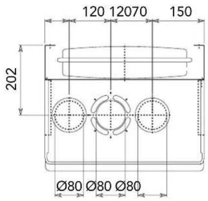
Top view
Bottom view

2 4
Fig. 1
Key
1 - 3/4" central heating flow outlet
2 - 1/2" domestic hot water flow outlet
3 - 1/2 " gas inlet
4 - 1/2" domestic hot water inlet
5 - 3/4" central heating return inlet
Technical Data
| MODEL | Heat output | Heat input Net | Domestic hot water heat input Gross | Boiler water contents | Domestic hot water circuit contents | ||
| kW kW | kW kW | kW Litres | es Litres | ||||
| Domina 102 | 30,0 | 12,7 | 33,1 | 14,5 | 30,0 | 1,5 | 0,8 |
| MODEL | Connections | Expansion vessel | Max. working pressure central heating circuit | Max. working pressure hot water circuit | |||||
| 1 | 2 | 3 | 4 | 5 | Capacity | Pre-pressurising value | |||
| ∅ | ∅ | ∅ | ∅ | ∅ | Litres | bar | bar | b | |
| Domina 102 | 3/4" | 1/2" | 1/2" | 1/2" | 3/4" | 10 | 1 | 3 | 6 |
| MODEL | Main injectors (mm) | Gas flow rates to main burners for central heating | Gas valve 1/2" | ||
| G20 - NG | G31 - LPG | G20 - NG | G31 - LPG | ||
| m^3/h | kg/h | ||||
| Domina 102 | 16x1,25 | 16x0,75 | 3,5 | 2,6 | H. V K4105G |
| MODEL | Gas supply pressures working | Gas pressure at main burner for central heating | Safety valve | ||||
| G20 - NG | G31 - LPG | G20 - NG | G31 - LPG | ||||
| min. | max. | min. | max. | ||||
| mbar | mbar | mbar | mbar | mbar | mbar | bar | |
| Domina 102 | 20 | 31 | 2,5 | 13,0 | 7,0 | 35,5 | 3 |
| MODEL | Domestic hot water production with Δt 30°C | Domestic hot water production with Δt 35°C | Max. working pressure domestic hot water | Protection level | Weight | |
| G20 - NG | G31 - LPG | |||||
| l/min. | l/min. | mbar | mbar | kg | ||
| Domina 102 | 14,3 | 12,3 | 13,0 | 35,5 | IP44 | 48 |
N.B. - The gas pressures at the burner and gas flows during the central heating phase given in the table refer to nominal boiler output. To reduce this output (where necessary), gas pressure must be reduced until the required output level is reached (see figures 4 and 5).
During domestic hot water production, gas pressures to the burner must correspond to the maximum output given in table for the type of gas.
Gas pressure must be adjusted during maximum draw-off of domestic hot water.
• Maximum working temperature for central heating flow: 85°C
• Maximum temperature of domestic hot water: 55°C, adjustable between 40°C and 55°C.
- Minimum domestic cold water pressure required for 95% heat input:
- Flow restrictor fitted (standard) - 1,2 bar;
- Flow restrictor removed - 0,5 bar
2.02 Boiler main components
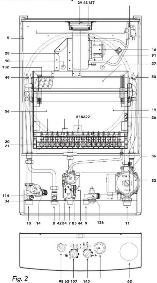
2.03 Boiler water flow diagram

Key
5 Room sealed compartment
7 Gas inlet
8 Domestic hot water outlet
9 Domestic hot water inlet
10 Central heating flow outlet
11 Central heating return inlet
14 Safety valve
16 Fan
19 Combustion chamber
20 Burner assembly
21 Main injector
22 Burner
26 Combustion chamber insulation
27 Copper heat exchanger for central heating and domestic hot water
28 Flue collector from heat exchanger
29 Internal flue exit
32 Central heating pump
34 Central heating flow temperature sensor
36 Automatic air vent valve
42 Domestic hot water flow temperature sensor
43 Air pressure switch
44 Gas valve
49 Safety overheat thermostat
50 Central heating flow limit thermostat
56 Expansion vessel
62 Time clock (option)
63 Central heating temperature adjustment
81 Ignition electrode
82 Sensor electrode
84 Primary gas valve solenoid
85 Secondary gas valve solenoid
90* Flue outlet test point
91* Air test point
98 On/Off/Reset switch
114 Low water pressure cut off switch
132 Flue gas deflector
136 Flow meter
145 Central heating pressure gauge
157 Domestic hot water temperature adjustment
187 Restrictor
* For use with flue gas analyser
2.04 Central heating adjustment (not normally required)
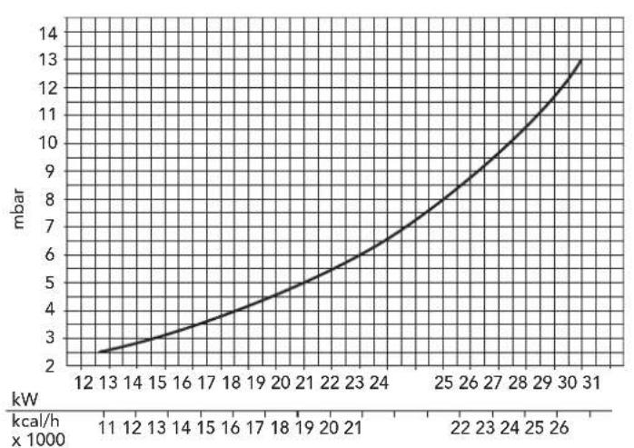
To adjust boiler heat input (thus also regulating heat output to the central heating water) simply adjust the main burner via the electronic control board (fig. 4, 5 and see paragraph 5.04 page 24).
The diagrams indicate the variation in heat output to the water as burner working pressure is varied.
Adjusting boiler output to the actual requirements of the central heating system will minimise boiler cycling thus saving fuel, varying the output has virtually no effect on the efficiency and combustion characteristics of the boiler.
Diagram of pressures and outputs with Natural gas
line
| x | y | |---|---| | 12 | 2.5 | | 13 | 2.7 | | 14 | 2.9 | | 15 | 3.1 | | 16 | 3.4 | | 17 | 3.7 | | 18 | 4.0 | | 19 | 4.3 | | 20 | 4.7 | | 21 | 5.1 | | 22 | 5.6 | | 23 | 6.1 | | 24 | 6.7 | | 25 | 7.4 | | 26 | 8.2 | | 27 | 9.1 | | 28 | 10.1 | | 29 | 11.3 | | 30 | 12.6 | | 31 | 13.3 | kcal/h × 1000Fig. 4 Fig. 5
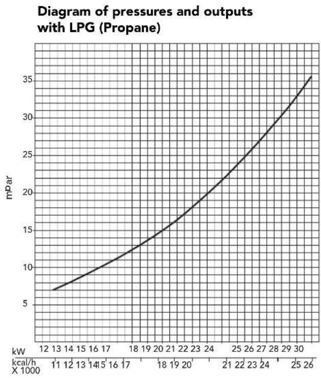
line
| kcal/h | Pressure (mPa) | | ------ | -------------- | | 12 | 7 | | 13 | 8 | | 14 | 9 | | 15 | 10 | | 16 | 11 | | 17 | 12 | | 18 | 13 | | 19 | 14 | | 20 | 15 | | 21 | 16 | | 22 | 17 | | 23 | 18 | | 24 | 19 | | 25 | 20 | | 26 | 21 | | 27 | 22 | | 28 | 23 | | 29 | 24 | | 30 | 25 |2.05 Pump characteristics
The pump head available for circulating the water is given in fig. 6.
N.B. - The pump is factory set at position 3. The pump is a Grundfos type 15-50 UPS series.
Grundfos Pump performance graph
Note - Minimum flow through boiler heat exchanger at any time should not fall below 6 litres per minute.
If the total volume of water in the system exceeds 40 litres an additional expansion vessel must be fitted to the central heating return pipe.
Pump performance curve Grundfos UPS 15-50

line
| Gal/min | in-wg (Line 1) | in-wg (Line 2) | in-wg (Line 3) | | ------- | -------------- | -------------- | -------------- | | 0.0 | 150 | 400 | 500 | | 0.2 | 100 | 300 | 450 | | 0.4 | 50 | 200 | 350 | | 0.6 | 0 | 100 | 250 |1 2 3 Speed settings
A Boilers pressure drop
B Available pump head C.H.
Fig. 6
| SAFETY VALVE SETTING (bar) | 3.0 | |||||
| VESSEL CHARGE PRESSURE (bar) | 0.5 | 1.0 | 1.5 | |||
| INITIAL SYSTEM PRESSURE (bar) | 1.0 | 1.5 | 2.0 | 1.5 | 2.0 | 2.0 |
| TOTAL WATER CONTENT of SYSTEM | EXPANSION VESSEL VOLUME (litres) | |||||
| LITRES | ||||||
| 25 | 3.5 | 6.5 | 13.7 | 4.7 | 10.3 | 8.3 |
| 50 | 7.0 | 12.9 | 27.5 | 9.5 | 20.6 | 16.5 |
| 75 | 10.5 | 19.4 | 41.3 | 14.2 | 30.9 | 24.8 |
| 100 | 14.0 | 25.9 | 55.1 | 19.0 | 41.2 | 33.1 |
| 125 | 17.5 | 32.4 | 68.9 | 23.7 | 51.5 | 41.3 |
| 150 | 21.0 | 38.8 | 82.6 | 28.5 | 61.8 | 49.6 |
| 175 | 24.5 | 45.3 | 96.4 | 33.2 | 72.1 | 57.9 |
| 200 | 28.0 | 51.8 | 110.2 | 38.0 | 82.4 | 66.2 |
| For syst. volumes other than those given above, mult. the syst. volume by the factor across | 0.140 | 0.259 | 0.551 | 0.190 | 0.412 | 0.33 |
SIZING OF ADDITIONAL EX PANSION VESSELS:
Deduct from the value given in the table the 10 litre vessel supplied.
Note:
- Fill C.H. installation to min. 1.5 bar.
- Expansion vessel must be fitted to central heating return pipe.
- The standard 10 litre expansion vessel is charged to 1 bar.
- The additional expansion vessel should be charged to 1 bar.
Pressure loss diagram
H mbar x 100

line
| Q (m³/h) | Value | | -------- | ----- | | 0 | 0 | | 0.5 | 1 | | 1.5 | 3 | | 2.512 | 8 |3. INSTALLATION DETAILS
Gas Safety (Installation & Use) Regulations: 1996
In the interest of safety, it is the law that all gas appliances are installed by a competent person in accordance with the above Regulations, Building Regulations/Building Standards Scotland, Codes of Practice, current I.E.E. Regulations and the byelaws of the Local Water Undertaking. Failure to comply with the Regulations may lead to prosecution; it is your responsibility to ensure that the law is complied with.
N.B. For Northern Ireland the rules in force apply.
Important - If the boiler is to be fitted in a timber framed building it should be fitted in accordance with the Institute of Gas Engineers document IGE/UP/7. If in doubt advice should be sought from the Local Supplier.
Location of Boiler
The installation of the Domina 102 must be on a suitable non-combustible load bearing wall which will provide an adequate fixing for the boiler mounting safety bracket assembly. The location should be in an area where the water pipes will not be subjected to frost conditions. In siting the combination boiler the following limitations must be observed:
The combination boiler may be installed in any room or internal space, although particular attention is drawn to the requirements of the current I.E.E. wiring regulations and in Scotland the electrical provisions of the building regulations applicable in Scotland, with respect to the installation of the combination boiler in a room or internal space containing a bath or shower.
Where a room sealed appliance is installed in a room containing a bath or shower any electrical switch or appliance control utilising mains electricity must be situated so that it cannot be touched by a person using the bath or shower.
Air Supply
The room or compartment in which the boiler is installed does not require a purpose provided vent when using the standard concentric flue.
Flue System
The boiler allows the flue outlet to be taken from the rear of the boiler, from either side or vertically.
A standard flue length of 0.75 metres is provided. Alternative lengths of two or three metres can be supplied (equivalent to wall thicknesses of up to 565, 1815 and 2815mm for rear flues, deduct 91mm plus distance from side wall for side outlet flues). It is absolutely essential, to ensure that products of combustion discharging from the terminal cannot re-enter the building, or enter any adjacent building, through ventilations, windows, doors, natural air infiltration or forced ventilation/air conditioning.
Gas Supply
If necessary the local Gas supplier should be consulted, at the installation planning stage, in order to establish the availability of an adequate supply of gas.
An existing service pipe must not be used without prior consultation with the Local Gas supplier.
A gas meter can only be connected by the Local Gas supplier, or by a Local Gas suppliers Contractor.
Installation pipes should be fitted in accordance with BS6891-1988.
Appliance inlet working pressure must be 20mbar MINIMUM, for NG and 37 mbar minimum for LPG.
Pipework from the meter to the combination boiler must be of an adequate size.
The boiler requires 3.5 m ^3 /h of natural gas, and 2.60 kg/h of LPG.
Do not use pipes of a smaller size than the combination boiler inlet gas connection.
The complete installation must be tested for gas soundness and purged as described in BS6981-1988. All pipework must be adequately supported. An isolating gas valve is provided and should be fitted on the boiler gas inlet. Please wait 10 minutes when lighting from cold before checking gas rate. Gas pressures should be checked after the boiler has operated for 10 minutes to reach thermal equilibrium.
Water System
Note - the boiler is designed for sealed systems only and must NOT be used on open vented systems.
Central Heating
Detailed recommendations are given in BS6798, BS5449, BS6700 and CP342 Part 2. Pipework not forming part of the useful heating surface should be insulated to prevent any heat losses or possible freezing (i.e. in roof spaces or ventilated underfloor spaces). Drain taps should be positioned at the lowest point of the system in accessible locations to permit the whole system to be drained down. The drain taps should be in accordance with BS2879. Copper tubing to BS2871, Part 1 is recommended for water carrying pipework. Pipework in horizontal runs should have a gradient where possible to facilitate the removal of air. Ensure that the boiler heat exchanger is not a natural point for air collection. A typical heating system with domestic hot water circuit is illustrated in fig. 8.
Important - If thermostatic radiator vales are fitted a bypass must be fitted to ensure a minimum flow rate through the boiler of 6 l/min. The bypass should be fitted as far as possible from the boiler.
Make Up Water
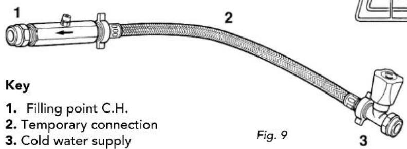
Provision must be made for replacing water lost from the sealed system. Reference should be made to BS6798, for methods of filling and making up sealed systems. There must be no direct connection between the boiler's central heating system and the mains water supply. The use of mains water to charge and pressurise the system directly, is conditional upon the Local Water Byelaws. Again any such connection must be disconnected after use. A typical temporary filling loop is shown in fig. 9.
Domestic Hot Water
Always fit a scale reducer in "hard water areas" (18 clarke degrees or over)". A 15mm copper connection point on the boiler for attaching to the main supply is provided. The maximum domestic water pressure for the inlet supply is 10 bar (145 P.S.I.). If the cold mains supply exceeds 5 bar (72 P.S.I.), a water governor or pressure reducing valve must be fitted by the installer into the mains supply in an inconspicuous but accessible position preferable between 3 and 5 metres (10-16ft) before the appliance. Such a valve must be approved by the Water Research Council.
Attention - is drawn to the Model Water Byelaws.
Fittings manufactured from duplex (alpha-beta) brass are not acceptable for underground use and certain water undertakings will not accept their use above ground.
Ensure all pipework is adequately supported
NOTE: A bypass must be fi tted as far as possible from the boiler if thermostatic radiator valves are fi tted throughout.

flowchart
graph TD
    A["Cold water"] --> B["Gas"]
    B --> C["Filling point C.H."]
    C --> D["Additional expansion vessel C.H. (if required)"]
    D --> E["Bypass"]
    style A fill:#f9f,stroke:#333
    style B fill:#ccf,stroke:#333
    style C fill:#cfc,stroke:#333
    style D fill:#fcc,stroke:#333
    style E fill:#ffc,stroke:#333
CLEARANCES:
* 600mm minimum clearance for servicing access
Fig. 10


Terminal Position

Minimum dimensions of flue terminal positions
| Dimensions Terminal position (kW input expressed in net) | Balanced flues room sealed | Open flues | |||
| Natural draught | Fanned draught | Natural draught | Fanned draught | ||
| A^a | Directly below an opening, air brick, (0-7 kW) opening windows, etc. (>7-14 kW) (>14-32 kW) (>32-70 kW) | 300 mm600 mm1500 mm2000 mm | 300 mm Not allowed 300 mm | ||
| B^a | Above an opening, air brick, (0-7 kW) opening windows, etc. (>7-14 kW) (>14-32 kW) (>32-70 kW) | 300 mm300 mm300 mm600 mm | 300 mm Not allowed 300 mm | ||
| C^a | Horizontally to an opening, air brick, (0-7 kW) opening windows, etc. (>7-14 kW) (>14-32 kW) (>32-70 kW) | 300 mm400 mm600 mm600 mm | 300 mm Not allowed 300 mm | ||
| D 300 mm 75 mm | Below gultured soil pipe, orom drain pipes | ||||
| E | Below eaves | 300 mm | 200 mm Not allowed 200 mm | ||
| F | Below balconies or car port roof | 600 mm | 200 mm Not allowed 200 mm | ||
| G 300 mm 150 m from a vertical drain pipe or soil pipe | b | Not allowed 150 mm | |||
| H 600 mm 300 m From Not allowed 200 mm external corner | |||||
| I | Above ground roof or balcony level | 300 mm | 300 mm Not allowed 300 mm | ||
| J | From a surface facing the terminal (also see 6.1.2) | 600 mm | 600 mm | N/A | 600 mm |
| K | From a terminal facing the terminal | 600 mm | 1200 mm | N/A | 1200 mm |
| L | From an opening in the car port (e.g. door, window) into the dwelling | 1200 mm | 1200 mm | N/A | 1200 mm |
| M | Vertically from a terminal on the same wall | 1500 mm | 1500 mm | N/A | 1500 mm |
| N | Horizontally from a terminal on the same wall | 300 mm | 300 mm | N/A | 300 mm |
| O | From the wall on which the terminal is mounted | N/A | N/A | N/A | 50 mm |
| P | From a vertical structure on the roof | N/A | N/A | See Table 2 and Fig. 6b | N/A |
| Q | Above intersection with roof | N/A | N/A | See Table 2 and Fig. 4 | 150 mm |
| NOTE N/A = Not applicable*In addition, the terminal should not be nearer than 150 mm (fanned draught) or 300 mm (natural draught) to an opening in the building fabric formed for the purpose of accommodating a built-in element such as a window frame, see Figure G21. Separation distances are linked to the rated heat inputs as shown.*This dimension may be reduced to 75 mm for appliances of up to 5 kW heat input. | |||||
Fig. 11
3.01 Drilling Template (Top Flue Application)
Select suitable mounting position for boiler, using the template mark flue outlet and boiler mounting points. Drill two 10mm holes 90mm deep to accept the wall plugs, fit wall plugs. Fit two special wall plugs on the wall as described in the fig. 12a. Fasten the wall bracket to the wall using an antitheft nut on the right side and a standard nut (M8) on the left side. Mount the boiler on the wall bracket and fi x using an antitheft nut on the left side and a standard nut (M8) on the right side. Using a core drill cut a 118mm diameter hole for the fl ue.
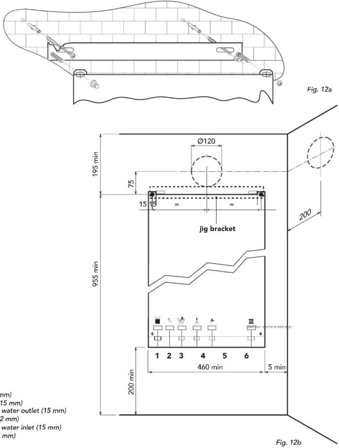
- CH flow (22 mm)
- Safety Valve (15 mm)
- Domestic hot water outlet (15 mm)
- Gas supply (22 mm)
- Domestic hot water inlet (15 mm)
- CH return (22 mm)
3.02 Restrictor
For boiler operation, the restrictor supplied with the unit must be mounted following the instructions below. Determine the correct size of fl ue restrictor required. Before inserting the fl ue gas duct in the boiler, check that the restrictor fitted is correct and that it is correctly positioned (see fig. 13).

Choice of restrictor:
- With concentric pipes: - up to 1m long + one bend, use the 52 mm restrictor.
- for flue lengths over 1 metre, use no restrictor.
- With 2 pipe system: - Calculate the total flow resistance of the air and flue pipes in metres (cap. 3.04.2)
- utilise the table shown below to choose the more suitable restrictor for the flow resistance calculated
| RESTRICTOR FOR TWO PIPE SYSTEMON DOMINA 102 | ||
| Total flow resistanceof flue system | Use restrictorsize | |
| minimum maxiumm mm | ||
| 0 m 20 m | 47 | |
| r20 m | 35 m 50 | |
| 35 m | 45 m 52 | |
| 45 m | 50 m | no restrictor |
3.03 Top Outlet Concentric Flue Connection
3.03.1 Vertical concentric connection

A vertical connector can be supplied for vertical discharge with concentric pipes.
The simple mounting and use of double lip gaskets at the joints makes this an extremely easy and safe option.
Fig. 14
3.03.2 Horizontal concentric connection
A 90° bend (fi g. 15) is supplied for the horizontal connection of air and fl ue gas pipes. This can be angled towards the chosen wall in degrees of 45°.

Notes on concentric horizontal installation
To locate the centre of the hole for passing the pipes through the wall, refer to fi g. 12b. Bear in mind that the two concentric pipes must slope downwards away from the boiler at a rate of about 3 mm/m to avoid rainwater entering the boiler. The concentric pipes making up the air - fl ue gas duct must be sealed with the gasket where they join the boiler (fi g. 16). Outside, the pipes should protrude from the wall between 10 and 60 mm (fi g. 16).
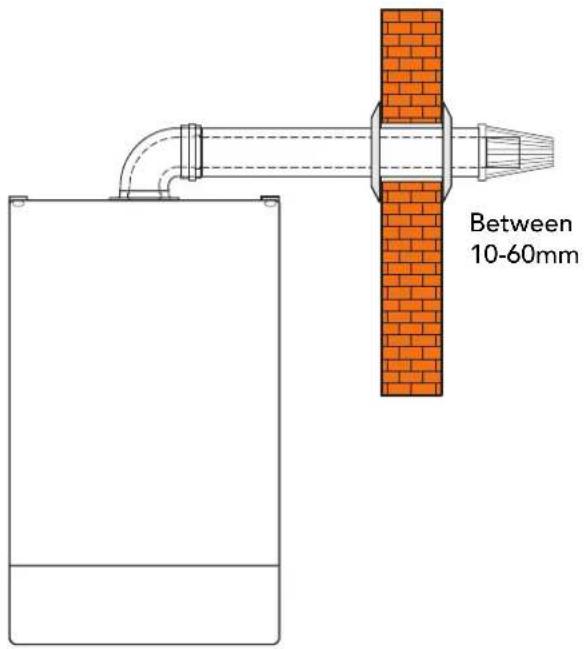
Fig. 16
3.03.3 Maximum concentric flue length
First table below shows the maximum flue lengths available for boilers with concentric systems.
For correct calculation remember to include the reduction for bends on second table. Please refer to 3.02 for use of restrictor
| Maximum flue lenght permissible | 100 mm concentric 125 mm concentric Vertical Horizontal* Vertical Horizontal* | |||
| Domina 102 4 m 3 m 5 m | 5 m | |||
*For horizontal Flueing the reduction for appliance bend or turret are already included.
| Reduction for bend | |
| 100 mm concentric bend 90° 1 m | |
| 100 mm concentric bend 45° 0,5 m | |
| 125 mm concentric bend 90° 0,5 m | |
| 125 mm concentric bend 45°0,25 m | |


Fig. 17b
3.04 Top Outlet: Two Pipe Flue System
3.04.1 Two pipe connection
Two separate ducts ∅80 for air intake and flue gas discharge can be directly connected to the boiler. For conversion mount the separate outlet kit ① to top outlet (see 3.03)
Insert blanking plate ② in remaining air intake
Fig. 18
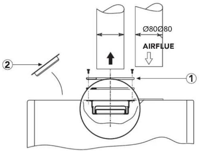
Connect flue duct to central hole ∅80 and air duct to left or right air intake hole ∅80. Insert blanking plate ② in remaining air intake.
A varied selection of accessories for two pipe systems are available from Ferroli (ref. to page 17). Before installing your system please check via calculation table at 3.04.2 you are not exceeding the maximum permissible length for the appliance.
IMPORTANT:
Notes on two pipe system installation:
When using the two pipe system the flue discharge pipe must have a 25mm air gap when passing through combustible materials. Where the flue discharge pipe passes through the airing space of an airing cupboard it must be protected by a non combustible guard or expanded metal giving an annular air gap of at least 25mm.
Where the flue discharge pipe passes through a wall containing cavity insulation, a non combustible sleeve must be fitted. Additionally a gap of 25mm between the sleeve and the insulation should be provided by cutting back the insulation or packing loose fill bead insulation with mineral fibre. Where the flue pipe is run through an unheated roof space it should be insulated with non combustible insulating material to prevent condensation. The flue pipe should be supported at intervals of not more than 1.8m and the support should be preferably below a joint.
3.04.2 Two pipe fl ue system
To determine the maximum length of flue and air pipe permissible.
The calculation is based on a standard reference resistance of 1 metre of 80 mm horizontal air intake pipe. For every configuration of the two-pipe system all components will have a resistance factor based upon this reference. (i.e. a 90 degree bend fitted in the flue line would attract a resistance factor equivalent to 2.5 Metres of horizontal 80mm pipe). This is expressed as X metres. Each boiler will have a maximum equivalent length of flue/air pipe and this is shown in the table as N metres. Therefore when calculating the proposed flue run the equivalent resistance of every length of pipe and every bend, whether air intake or flue discharge is added together to give an actual total flue length. The final figure calculated must not exceed the permitted maximum length (N metres) for each boiler type.
Calculation Routine
- Identify all the components needed to complete the proposed flue/air pipe run.
- Calculate the sum of all the equivalent lengths (see table at next page).
- For boilers, which may require a flue restrictor, refer to table at page 13 (par. 3.02) to ascertain the correct size and add this resistance to your total.
- Check and verify that the total flue/air pipe length (flow resistance) does not exceed 50 mt. maximum permitted for Domina 102.
IMPORTANT: Resistance factors apply to standard férroli components only.
3.04.2 (continued)
Tab. 1 - Pipes and
| fi ttings reduction table | Vertical | Horizontal | Vertical | Horizontal | |
| Description | |||||
| Accessories∅80 | Male-female flue/Air pipe1 m - ∅ 80 | 1 | 1 | 1 | 2 |
Female-female bend45° ∅ 80 m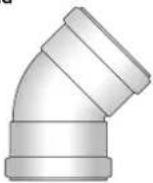 | 1,2 2,2 | ||||
Male-female bend90° ∅ 80 m | 1,5 2,5 | ||||
Spigot-and-socketreduction ∅ 100/80 mm | 0 | ||||
| REDUCTION | |||||
| AIR FLUE | |||||
| Vertical | Horizontal | Vertical | Horizontal | ||
| Accessories∅80 | Dscription | ||||
Horizontal flue terminal∅ 80 mm | 5 | ||||
| Air intake terminal∅ 80 mm[4740] | 2 | ||||
Outlet flue/air inlet for concentric system∅ 100/60 mm | |||||
Pipe fitting for outlet flue∅ 80 mm | 4 | ||||
Outlet flue/air inlet for connection with split end∅ 80 mm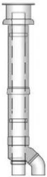 | |||||
For further accessories please refer to:
"Flue system manual for room sealed boiler"
Example of calculation for wall inlet/outlet with 2 pipe system maximum total fl ue length: 50 metres

Fig. 19
Attention:
Remove the fl ue diaphragm.
The fl ue + air Pipes must have a 3% drop away from the boiler to outside
| REF. | N° OF PIECES | DESCRIPTION | LENGTH OR REDUCTION |
| 1 | 1 | Air bend 80 mm R/D = 0,75 | 1,5 m |
| 2 | 13 | Horizontal air pipe | 13,0 m |
| 3 | 1 | Air wall terminal | 2,0 m |
| 5 | 1 | Flue bend 80 mm R/D = 0,75 | 2,5 m |
| 6 | 13 | Horizontal fl ue | 26,0 m |
| 7 | 1 | Air wall terminal outlet fl ue | 5,0 m |
| TOTAL | 50,0 m | ||
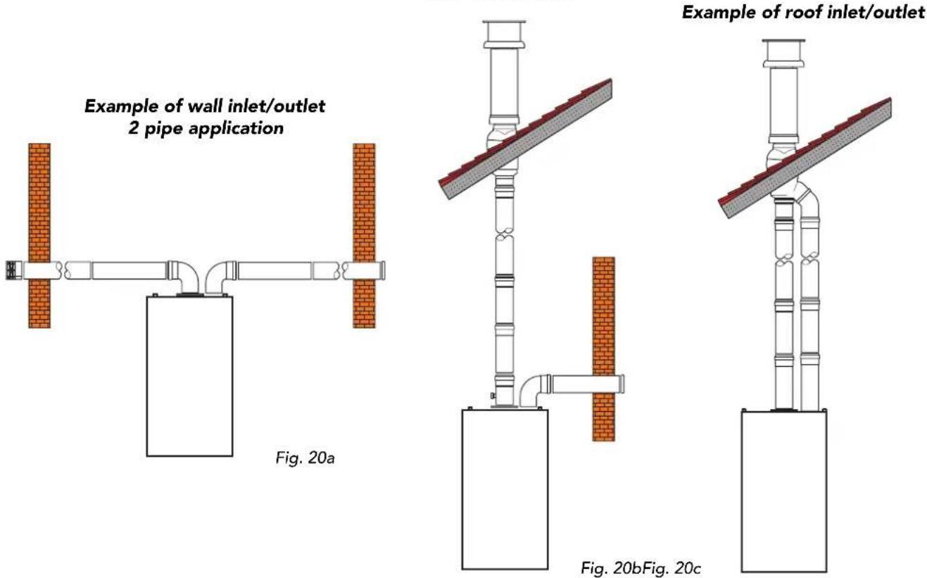
3.04.3 Example of other installation with two pipe systems
Example of direct roof fl ue outlet and wall air inlet
3.05 Connecting the central heating and domestic hot water circuits
Connect to the relevant connections as indicated in fig. 1. Connect the pressure relief valve discharge pipe (15mm) to the outside of the building, where possible over a drain. The discharge must be such that it will not be hazardous to occupants and passers-by or cause damage to external electric components or wiring. The pipe should be directed towards the wall. To ensure long life, the heating circuit should be correctly sized and fitted with all the controls necessary to ensure correct functioning and operation. The differential between the boiler flow and return pipes should not be more than 20°C. You are advised not to use the boiler with return temperatures of less than 50°C in order to prevent patches of condensation forming, having a corrosive effect on boiler components.
3.06 Boiler water characteristics
If the water is harder than 18 clarke degrees, the water used should be treated to avoid possible scale in the boiler caused by hard water or corrosion by aggressive water. It should be remembered that as a result of its low thermal conductivity, even scale of just a few millimetres thick can lead to considerable overheating of the boiler walls, resulting in serious problems.
IT IS ABSOLUTELY VITAL THAT THE WATER USED IS TREATED IN THE FOLLOWING CASES:
a) Extensive systems (containing large quantities of water);
b) Frequent additions of water to top-up the system;
c) Domestic hot water circuits
If the system requires partial or total emptying, you are recommended to refill it with treated water.
3.07 Filling
When cold, system pressure should be about 1 bar. If while running venting off of air dissolved in the water causes the pressure of the central heating system to drop below 0.5 bar, the user must utilise a fi lling loop to bring it back to the original value. During operation, water pressure in the boiler when hot should be about 1.5 - 2 bars. After fi lling, always close and disconnect the fi lling loop.
Note - If there is a possibility of air pockets forming in certain points of the central heating system flow and return pipes, you are recommended to fit an air vent valve at these points.
Note - When the boiler is installed below the level of the central heating a system, single check valve should be fitted in the flow to prevent gravity circulation around the heating system.
3.08 Gas connection
Gas connection should be carried out using a rigid pipe.
The flow at the gas meter should be sufficient for the simultaneous use at full gas rate of all appliances connected to it. Connect the gas supply to the boiler according to current regulations. The diameter of the gas tube leaving the boiler is not the determining factor in choosing the diameter of the pipe between the appliance and the meter. This must be selected in relation to length and pressure drop and in any instance should not be less than 22mm.
The whole of the gas installation including the meter should be inspected and tested for soundness and purged in accordance with BS6891-1988.
N.B. - The filling loop will be fitted by the installer at the time of installing the system. It is NOT a part of the boiler.
3.09 Electrical connection
The boiler must be connected to a single phase 230 V 50 Hz electricity supply with a 3 A max. fuse and a bipolar switch with contact opening of at least 3 mm fitted between the boiler and the electricity supply. The boiler must always be connected to an efficient earth installation. Under the electrical box, there is a 3 pole terminal block for connecting the boiler to the mains (230 V 50 Hz) and a 2 pole board for connecting a room thermostat (RT). To connect, undo the screws fixing the terminal block box and connect the wires, ensuring correct polarity of the terminals. It should be noted that there is low voltage (24 V) between the room thermostat contacts.
When the boiler is connected to an electricity main, it is essential TO OBSERVE CORRECT POLARITIES (LIVE: brown cable, NEUTRAL: blue cable, EARTH: yellow-green cable).
All wiring must conform to current I.E.E. regulations.
Note: If the power supply cable has to be replaced, use "0.75mm (24/0.20) heat resisting cable only to BS6500 with a maximum external diameter of 8 mm.
Note - When connecting a room thermostat or external timer, do not link the power supply of these devices to the switching contacts. The switch contacts must be voltage free. Any mains powered devices must utilise mains power solely to drive the timer motor.
Applying mains voltage to the switch contacts will irreparably damage the circuit board.
Although this boiler can also be used without a room thermostat, you are recommended to install one for the following reasons:
Greater comfort conditions due to more accurate control of room temperature.
Greater energy savings.
3.10 Differential air pressure switch (fig. 2 - part 43)
The differential air pressure switch is a safety device which allows the main burner to ignite only after having verified that the fan is working correctly. If the difference in pressure between the flue gas discharge pipe and the air intake pipe is not at least equal to the minimum pressure switch calibration value, the pressure switch contacts do not close and the gas valve is thus prevented from opening.
In addition, the electrical circuit of the boiler is designed so that if for any reason the air pressure switch contacts remain closed when the fan stops, the burner will not start up again.
3.11 Checks
Fill the central heating system as described previously (3.07) and check there are no leaks in the domestic hot water and boiler water circuits. Check that there are no gas leaks on the boiler or the supply to the boiler. Also check that the electrical connections are correct.
3.12 Installing a room thermostat (72) (fig. 21b)
To connect the thermostat:
Open the electrical box on the base of the appliance and remove the "jumper cable" between terminals 3 and 4.
Connect the room thermostat (72) as shown in figure 21b.
3.13 Time clock fixing (optional)
- Remove outer case by removing two securing screws from the rear bottom corners and lift off.
- Remove screw securing facia panel and swing facia panel down.
- Remove rear cover from facia.
- Remove clock blanking plate from the boiler facia panel.
- Mount clock into facia panel using two screws and spacers provided.
- Take the black cable containing the blue and brown wires and connect the loose spades to clock terminals 1 & 2.
- Connect the plug end of the cable to terminal X2 contacts 1 + 2 of main circuit board.
- Remove the connector link from the 2 wires located behind the clock position.
- Connect these to terminal 3 and 5 of the clock.
- Replace everything in reverse order.
- Please refer to page 43 of User manual for use of time clock
Terminal 3 & 4 situated underneath the boiler in the terminals compartment
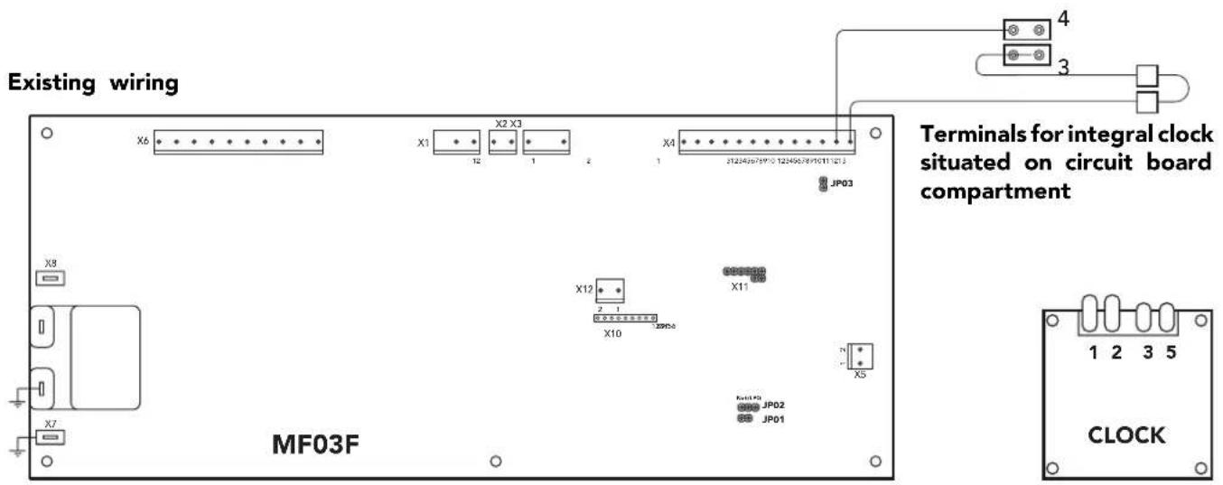
Fig. 21a
Wiring for integral clock and/or external controls

Fig. 21b
4. COMMISSIONING AND TESTING
4.01 Checks to be carried out before starting up for the first time
When starting the boiler up for the first time check:
- that the gate valves between the boiler and central heating system are open;
- that the central heating system is filled and vented;
- that there are no gas or water leaks from the central heating system or boiler;
- that the electric connections are correct and the earth wire of the boiler is connected to an efficient earthing installation and a 3amp. fuse is fitted to the isolator;
- that there are no fl ammable liquids or materials near the boiler;
4.02 Starting up the boiler
- Open the gas cock upstream of the boiler.
- Vent air present in the pipe upstream of the gas valve.
- Turn on the electrical supply to the boiler.
- Rotate the ON-OFF-Reset switch (part 98) into the ON position.
- Check inlet working gas pressure, burner pressures and gas rate.
At this point, choose whether the boiler is to be used for central heating and domestic hot water production or for domestic hot water production only. If the former is chosen (central heating and domestic hot water production), turn the knob 63 (fig. 2) to the "Winter" position. Set the knob above 50°C and set the room thermostat (if fitted) to maximum. The burner ignites and the boiler starts to function automatically, controlled by its control and safety devices.
If the latter is chosen (domestic hot water production only), position the knob 63 (fig. 2) on the "Summer" position. In this mode the boiler is ready to operate automatically whenever domestic hot water is drawn off.
Note - If after completing the start-up procedure correctly, the burners fail to ignite and the boiler shut down warning lights up, wait about 15 seconds then rotate the knob 98 (fig. 2) against spring pressure to the RESET position and release it. The reset electronic control unit will repeat the start-up cycle.
Note - In central heating mode after resetting the boiler will go into it 2 minute delay before starting up again. If after a second attempt the burners still fail to ignite, consult the paragraph "Troubleshooting".
Note - If there is a power failure while the boiler is in operation, the burners automatically go out and re-ignite when the power returns.
4.03 Shutting down
Close the boiler isolation gas cock and turn off the electricity to the boiler.
Important: If the boiler is not to be used for lengthy periods during the winter, to avoid frost damage, you are recommended to drain the water from the circuits (domestic hot water and central heating). Alternatively, drain the domestic hot water system only and add special anti-freeze to the central heating system.
4.04 Checks and controls after first start-up
- Check there are no leaks in the gas and water circuits.
- Check correct boiler start up by carrying out start up and shut down tests using the boiler stat.
- Check the integrity of the air-flue pipes during boiler operation.
- Check that the gas consumption indicated on the meter corresponds to that given in Technical Data (page 5).
- Check that water is circulating correctly. Balance the radiators to ensure that the flow and return differential does not exceed 20^ C.
- Check that when operating in the "Winter" mode, the pump stops and domestic hot water is produced correctly when the hot water tap is turned on.
- Check that in the "Summer" mode, the burner lights up and shuts down correctly when the domestic
hot water tap is turned on and off.
- Check that the domestic hot water flow and T correspond to the table. Do not rely on empirical measurements. Temperature should be measured using thermometers as near as possible to the boiler, in mind the heat loss from the pipes.
- Check that the gas valve modulates correctly both during the central heating phase and the domestic hot water production phase.
• To determine combustion efficiency and the composition of the flue gases (refer to 6.04) - If any of the above are not correct refer to Technical Data (page 5). Adjustment (page 23) and Fault Finding (page 32).
5. ADJUSTMENT AND GAS CONVERSION
5.01 Adjusting the pressure and flow rate to the main burner
This boiler operates on the flame modulation principle. It has two fixed pressure values, minimum and maximum, which must be as shown in the table (pages 5), whichever type of gas is used.
Note - Because correct minimum and maximum pressures are critical to the efficient operation of the boiler it is ESSENTIAL that the following adjustments are carried out by COMPETENT personnel ONLY.
5.02 Adjusting minimum and maximum pressure Honeywell V K4105G gas valve
- Connect suitable pressure gauge to burner test point "B" downstream of the gas valve.
- Disconnect the pressure compensation tube «F».
- Remove the protective cap «C».
- Adjust potentiometre P3 (on the main board) at minimum (clockwise).
- Operate boiler for central heating
- Adjust minimum pressure by rotating screw «D» clockwise to reduce pressure and anticlockwise to increase pressure.
- If it is not possible to achieve the right pressure adjust minimum pressure by potentiometer P5
- Adjust potentiometre P3 at maximum (anticlockwise)
- Adjust max pressure by rotating screw «E», clockwise to increase pressure and anticlockwise to reduce pressure.
- Reconnect the pressure compensation tube «F».
- Replace protective cap «C».
Maximum + Minimum possible gas pressures are now set. Range Rating the central heating is not necessary (see paragraph 5.04).
Key
A = Gas inlet test point
B = Gas outlet test point (burner pressure)
C = Protection cap
D = Min. pressure adjusting screw
E = Max. pressure adjusting screw
F = Balancing tube

Fig. 22
5.03 Adjustment potentiometers

P1 = C.H. temperature adjustment
P2 = D.H.W. temperature adjustment
P3 = C.H. output adjustment
P4 = Ignition gas pressure adjustment
P5 = Minimum gas pressure adjustment
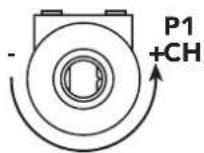
Fig. 23

5.04 Adjusting maximum output for central heating system (fi g. 23)
This adjustment must be carried out electronically using the "P3" adjustment screw starting with a cold central heating system. Connect a pressure gauge to the pressure test point downstream of the gas valve. Rotate the temperature adjustment screw to maximum then regulate the pressure to the value required, consulting the diagram (figs. 4 and 5) page 7. Once this operation is complete, start up and shut down the burner two or three times using the thermostat. Check each time that the pressure values remain as adjusted and that the burner ignites correctly. Otherwise further adjustment is necessary until the pressure remains stable on this value.
N.B. - when carrying out this operation ensure that the boiler thermostat is set to maximum otherwise the adjustment will not be accurate.
5.05 Adjusting central heating flow temperature
Central heating water temperature is adjusted by rotating the control knob (fig. 2 - part 63). Rotate the knob clockwise to increase water temperature, anticlockwise to reduce water temperature. Temperature can be varied from a minimum of 30^ C to a maximum of 85^ C. However, we recommend not operating the boiler below 50^ C.
5.06 Adjusting room temperature (when a room thermostat is fitted)
Room temperature is controlled by positioning the room thermostat knob to the required value. The thermostat automatically controls the boiler, temporarily interrupting the electrical supply subject to the room heat requirements.
5.07 Adjusting the central heating flow t by varying pump flow-head
The thermal head t (the difference in temperature between the delivery water and return water in the central heating circuit) must be less than 20^ c. This is obtained by varying pump flow rate and head using the multi-speed variator (or switch) on the pump itself. Increasing the pump speed reduces t and vice versa. The minimum differential must not be less than 11^ C.
5.08 Adjusting central heating system pressure
The pressure of water in the central heating system, read on the control panel pressure gauge, is adjusted as described in paragraph 3.07.
N.B.- To avoid incurring unnecessary expense, in the event of boiler shut down, check that this is not caused by a lack of electricity or gas, or low water pressure before calling the Customer Technical Service Helpline.
5.09 Gas conversion
The following adjustment and conversion operations must be carried out by competent personnel. FERROLI Limited accepts no liability for damage to property or personal injury resulting from tampering with the boiler by unauthorised persons. To convert the boiler from Nat Gas to LPG and vice versa, the main burner injectors must be replaced. Minimum and maximum pressures must then be adjusted on the gas valve (see Adjustment page 23). JP02 must be moved to the LPG position.
Note: After converting the boiler from natural gas to liquid gas, fit the orange plate in the conversion kit near the data plate.
Note: injector diameters and pressures at the main burner are given in Technical Data (page 5).
6. MAINTENANCE AND CLEANING
The following operations must be carried out by Corgi registered engineers only.
6.01 Annual Servicing
The following should be checked at least once a year:
• Water pressure in the central heating system when cold should be about 1 bar. If this is not the case, bring it back to this value.
- Check control and safety devices (gas valve, flow meter, thermostats, etc) are functioning correctly.
- The burner and heat exchanger must be clean. To avoid damage, always clean them with a soft brush or compressed air. Never use chemical products.
- The expansion vessel must be checked (precharge 1 bar).
- Check there are no leaks in the gas and water circuits.
- Check the air-flue gas duct terminal is free from obstructions and sound.
- The electrodes must be free from corrosion build up and correctly positioned.
- Gas flow and pressure must correspond to the values given in the Technical Data (page 5).
• The pump must be free to rotate.
6.02 Cleaning the boiler and burner
The boiler should be serviced annually. The heat exchanger and burner must never be cleaned with chemical products or steel brushes. Particular attention must be paid to all seals and fixings associated with the room-sealed compartment (gaskets, grommets, etc). Air leakage would cause pressure inside the compartment to drop, possibly tripping the differential pressure switch and thus shutting down the boiler. After cleaning particular attention should also be paid to checking stages of start-up and operation of the thermostats, gas valve and pump.
6.03 Servicing procedure
- Visually check boiler for correct installation and flueing.
- Isolate electricity supply + check fuse is 3amp.
- Remove case by undoing the two screws locate at the bottom rear corners, lift slightly and pull forward.
- Carry out preliminary electrical checks at boiler junction box. This is located in the centre of the boiler at the bottom and can be accessed be the removal of a single screw. Any faults found must be rectified before proceeding.
- If electrical checks prove O.K. replace cover and secure with screw.
- Attach a manometer to the boiler gas inlet test point, turn on electricity and fire boiler for hot water, check inlet pressure. This should be 20mbar minimum for NG and 37mbar for LPG. If this is not the case there is a supply problem and this will need to be remedied.
- If inlet pressure is O.K. shut down boiler and remove manometer from gas inlet pressure test point and attach it to the boiler burner pressure test point. Reseal inlet pressure test point.
- Fire boiler for hot water and check that the maximum pressure is 13.0mbar for NG and 35.5mbar for LPG. Turn off tap. Turn P3 on the main circuit board to minimum and fixe the boiler for heating, check that the burner pressure reads 2.5 mbar for NG and 7.0mbar for LPG. Turn P3 back to max position. Shut down boiler, remove manometer, seal test point and re-attach modureg lead. If the pressures are not as specified they will need to be adjusted on the gas valve (see page 23 - installation manual).
- Remove fan by undoing the two fan securing screws tilt the front of the fan upwards to detach it from the securing pin and withdraw it from the boiler, disconnect the wires and air pressure switch tubes.
- Take off the combustion chamber cover by removing the three securing screws.
- Lift off flue hood and flue baffle plate.
- Pull off the ignition and flame rectification leads from their respective electrodes.
- Undo the gas union in the centre of burner rail and take out the two securing screws. Remove the burner rail and clean rail and injectors.
-
Remove two screws securing the burner assembly and remove the assembly. Clean burners.
-
Clean heat exchanger with a soft brush.
- Re-assemble baffl e, fl ue hood and fan assembly, secure with screws previously removed.
- Refi t burner assembly and burner rail.
- Reconnect ignition and flame rectification leads.
- Reconnect gas union and tighten.
- Refi t combustion chamber cover, secure with screws.
- Examine seals on room sealed cover refi t cover and secure with screws.
- Turn on gas and electricity.
- Fire boiler and check all gas joints for soundess.
- Check flame picture and all controls for correct operation.
- Check room sealed cover for leakage.
- Check domestic water flow rate and temperature is within specifications.
- Check operation of all safety cut off devices.
- If a combustion analyser is to be used there are test points provided on the front of the room sealed cover. The right hand grommet is for air and the left hand one is for fl ue gas. The boiler must reach operating temperature before this test is carried out (normally 10-15 minutes). CO/CO2 ratio should not exceed 0.0040. Immediately after servicing (0.0080 at any other time)
- Refi t case and secure with screws.
- Leave boiler set to customers requirements.
6.04 Flue Gas Analysis
- The appliance should be checked visually for obvious defects.
- After removing the jacket on the boiler there are two t
- Open the air and fl ue gas test points;
- Introduce the probes as far as the retainer;
- Turn on the hot water tap;
- Turn the domestic hot water stat to maximum;
- Allow the boiler to reach thermal equilibrium (10 - 15 m
- Take reading;
- The CO/CO _2 ratio should be 0.0040 or below. If the must be carried out and the cause remedied.
- Following a full strip down service and after reach 0.008 or below.
N.B.: To ensure correct readings the boiler must have boiler before thermal equilibrium has been attained w

Fig. 24
7. REPLACEMENT OF PARTS
7.01 Initial procedure
a) The boiler is cold, electricity supply is isolated, and the gas supply is turned off at the inlet of the boiler
b) For replacement of parts where water connections are broken, it will be necessary to isolate and drain either or both the central heating or domestic hot water circuits of the boiler. The cold water mains inlet is isolated at the inlet cock. The D.H.W. is drained by opening a hot tap.
The C.H. flow and return cocks are turned off at the isolation cocks. The C.H. is drained via the pressure relief valve (twist about 1/3 of a turn).
c) Remove components following special notice below and replace in reverse order.
d) Ensure water and gas washers are in good condition.
7.02 Final procedure
- Re-open cocks and re-charge the system to about 1 bar, and vent boiler and radiators. Re-charge to 1 bar if necessary.
- Upon completion of the work the following. Should be checked:
I) Gas soundness of all joints
II) Water soundness of all joints
III) The electricity supply.
IV) The pressure of the sealed system and top up w
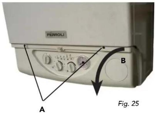
7.03 To lower the control panel (fig. 25)
- Remove the two fixing screw (fig. 25) "A"
- Rotate down the front panel "B"
7.04 Gas valve (fig. 26)
• Isolate gas and electricity supplies
- Remove outer case (two screws bottom rear corners)
- Remove the two securing screws and lower control panel
- Disconnect electrical connections from valve ("A")
- Disconnect plastic tube "C"
- Loosen the connection "D" on gas pipe and the gas inlet connection of the boiler "E"
- Remove the two fixing screw "E" below gas valve
- Slide out gas valve
- Remove four fixing screw "F" on top of the valve and disconnect the gas pipe
- Remove bottom connection from gas valve.
- Fit top + bottom gas connections to the new gas valve and replace in reverse order

Fig. 26
7.05 Air pressure switch (fi g. 27)
- Isolate electricity
- Remove outer case (two screws bottom rear corners)
- Open room sealed department
- Remove the two screw "A" fixing air pressure switch
- Disconnect electrical leads "B"
- Remove pressure sensing tubes (white=D; Red=C)
- Note relevant positions of all connections and replace in reverse order.

Fig. 27
7.06 D.H.W. temperature sensor or Central Heating Temperature Sensor (fi g. 28)
•, Isolate electricity and water supplies
- Remove outer case (two screws bottom rear corners)
- Remove the two securing screws and lower control panel
•, Identify the sensor from figure 28
•, Disconnect electrical connection to the sensor
•, Drain the affected service either D.H.W. or C.H.
•, Unscrew the sensor
•, Replace in reverse order
7.07 Water Pressure Switch (fig. 28)
•, Isolate electricity and water supplies
- Remove outer case (two screws bottom rear corners)
- Remove the two securing screws and lower control panel
•, Identify the switch from figure 28
•, Disconnect electrical connections + note positions to the switch
- Drain the boiler
•, Unscrew the sensor
•, Replace in reverse order
7.08 Safety Valve (fig. 28)
• Isolate electricity and water supplies
- Remove outer case (two screws bottom rear corners)
- Remove the two securing screws and lower control panel
• Identify valve from fig. 28
- Drain the boiler
- Release the outlet union to the valve and undo the valve union connection
- Remove the valve outlet fitting
- Replace in reverse order
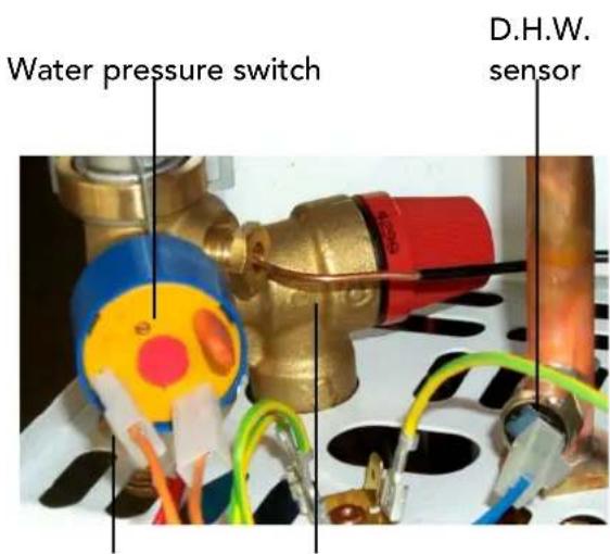
C.H. sensor
Safety valve
Fig. 28
7.09 Removal of burner (fi g. 29)
• Isolate gas and electricity supplies
- Remove outer case (two screws bottom rear corners)
- Remove room sealed cover
- Disconnect ignition and flame rectification leads "A"
- undo gas rail union "B"
- Undo two screws securing the burner assembly to the boiler combustion chamber "D"
- Withdraw the burner assembly
7.10 Injectors (fig. 29)
• Proceed as 7.07
- Remove fixing screw "C" on both sides of gas manifold
- Remove gas manifold
• Unscrew and remove injectors;
• Clear or change injectors
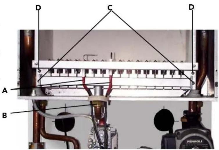
Fig. 29
7.11 Removal of fan (fig. 30)
• Isolate gas and electricity supplies
- Remove outer case (two screws bottom rear corners)
- Remove room sealed cover
- Disconnect fan electrical leads "A" and note positions
- Disconnect air pressure tubes from air pressure switch "B" + note positions
- Undo two screws securing fan assembly "C"
- Remove fan from boiler
- Swap mounting plate over to new fan + replace in reverse order
7.12 Limit thermostat, or overheat cut off thermostat (fig. 30)
- Isolate electricity
- Remove outer case (two screws bottom rear corners)
- Remove room sealed cover
• Identify the location of thermostat from fig. 30
• Pull out thermostat from tube, with its spring - Remove electrical connections from thermostat
- Remove spring from thermostat
- Replace in reverse order
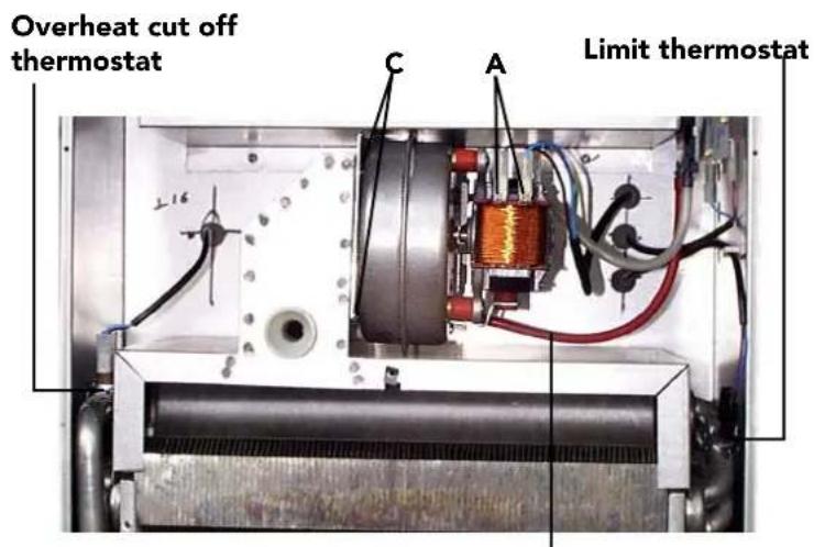
Fig. 30
B
7.13 Spark or flame detection electrode
(fi g. 31)
• Isolate gas and electricity supply
- Remove outer case (two screws bottom rear corners)
- Open room sealed compartment and combustion chamber
• Identify electrode from fig. 31
- Unplug electrical connection "A" from sensing electrode
- Remove fixing screw and remove flame detection electrode
- Remove the two fixing screw from spark electrode plate and remove it.
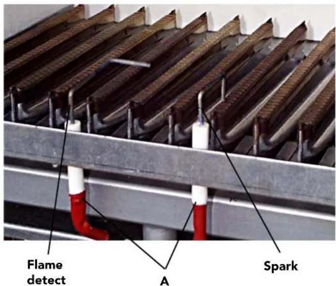
Fig. 31
7.14 D.H.W. flowmeter
• Isolate electricity and water supplies
- Open a hot water tap to release water pressure from the domestic side of the heat exchanger, close tap.
- Remove outer case (two screws bottom rear corners).
- Remove two screws from control panel and tilt forward
• Take off protective cover from main PCB and unplug flow meter lead from terminal X6
- Place a piece of cloth or some other absorbent material over rear of control panel to catch any drops of water that may be released when removing the flow meter
- Using a 24mm open ended spanner, undo flow meter unions "A" and "B" taking care not to twist the copper tubing (access through base panel).
- Remove flow meter, check + clean filter + restrictor + fit to new flow meter.
• Reassemble in reverse order.

natural_image
Close-up of a brass faucet with labeled parts A and B, showing internal components and wiring (no text or symbols beyond labels)Observe the correct position of components as shown in fig. 32b
Key
37 Cold water inlet filter
38 Gasket
39 Cold water flow limiter

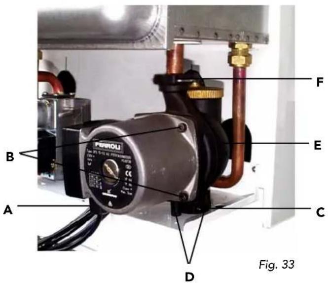
7.15 Pump (fi g. 33)
Replacement of pump head
• Isolate electricity and flow and return pipes
- Remove casing (two screws bottom rear corners).
- Remove the two securing screws and lower control panel
- Release pressure from boiler via pressure relief valve
• Unplug the pump lead "A" from the pump head
- Place a piece of cloth or other absorbent material over the rear of the control panel to catch any drops of water that may fall when the pump head is removed.
- Using a 4mm allen wrench undo the four allen screws "B" in the pump head, lift away pump head from the pump body
- fit new head into pump body and secure with the allen screws tightening evenly.
- Replace electrical connection.
Replacement of pump body (fig. 33)
• Proceed as for removal of pump head
- Disconnect the expansion vessel connecting pipe "E" from the rear of the pump body by removing the U clip from the left hand side
- Disconnect the boiler return pipe and disengage the pump lower connection by removing the U clip "C"
- Disconnect the pump to heat exchanger connection by removing the U clip "F"
- Unscrew the two screws on bottom of pump "D"
- Turn the pump body through 90°, pull the bottom forward and withdraw the pump body
- Reassemble in reverse order taking care to ensure the O-rings are in place and undamaged.
7.16 Removal of heat exchanger
• Isolate gas, water and electricity supplies
- Remove casing (2 screws bottom corners)
- Remove the two securing screws and lower control panel
- Drain heat exchanger for both CH + DHW
- Remove sealed compartment front panel
- Disconnect the overheat thermostat and central heating limit thermostat
- Remove the main burner, fan, flue hood and flow meter as described previously
- Remove the pump to heat exchanger flow connection and locknut
- Undo the domestic water outlet connection and locknut
- Lift out heat exchanger
• Re-assemble in reverse order
8. FAULT FINDING
Before beginning any fault finding ensure that gas, water and electricity are available.
WARNING: DO NOT link any terminals on block X10 or X11 as this will damage the PCB beyond repair.
8.01 Operating Sequence
With the power established the boiler is in its stand-by mode i. e. power on but no demand. The operational sequence for C.H. and D.H.W. are as follows:
Central Heating Mode
External Call for Heat: The temperature regulator, built in or remote clock and room thermostat, if fitted, must all call for heat. This will cause the pump to run.
Internal Call for Heat: C.H. flow temperature sensor, 88°C high limit and low water pressure switch all calling for heat. If both external and internal calls for heat are present the MF03 PCB will energise.
In demand the fan will go to high speed causing the air pressure switch to operate. If the overheat (100°C) stat is closed circuit the ignition will operate and the gas valve will be energised.
The burner will light at ignition burner pressure, automatically range rating itself up to the heating load, then modulating down when the boiler reaches the desired flow temperature. When the central heating is satisfied the burner will go off and the fan stops i.e. stand-by mode.
Note - If the boiler thermostat is set to maximum than the burner pressure will go to maximum effectively bypassing the auto range rating facility
Domestic Hot Water Mode
External Call for D.H.W: Flow meter registers at least 2.5 litres/min flow to the hot water taps.
Internal Call for D.H.W: Hot water flow temperature sensor 88°C high limit stat and low water pressure switch calling for heat.
If both internal and external calls are present the boiler follows the same sequence as for C.H. to light the burner. However, for D.H.W. the burner will go straight to maximum and then modulate once the water reaches the set temperature of the control thermostat. Turning the tap off will return the boiler to stand-by mode.
Note: Following shut down of the D.H.W. or C.H. the boiler will go into a three minute central heating delay.
8.02 Limit thermostats
| T/Stat | Location | Function | Nominal Operating Temperature | Circuit | Wiring Colours |
| C.H. Limit | Top RHS of Heat Exchanger | Shuts downmain burner if boiler thermostat fails | 88°C | Low voltage DC | Blue Brown |
| Frost | Incorporated in C.H. Sensor | Fires the boiler and runs pump to maintain minimum water temperature | 7°C - 14°C | Low voltage DC | Red Red |
| Overheat | Top LHS of Heat Exchanger | Protect boiler by stopping ignition and cuts power to gas valve | 100°C | 240V AC | Brown Blue |
The MFO3 PCB has fivediagnostic lights, each light corresponds to a particular function and will light in turn as the boiler goes though its sequence of operations.
In order, the five lights indicate:
1 Boiler On Indicate
2 Boiler Shut down warning
3 Domestic Hot Water circuit ON
4 Central Heating standby (Flashing Light)
Central Heating circuit ON (Permanent Light)
5 Insufficient pressure in Central Heating System (Flashing Light)
Electric power supply ON (Permanent Light)
Note: Always check for sufficient gas supply (20mbar inlet working pressure for NG and 37mbar for LPG). Minimum of 22 mm diameter pipework on C.H. flow and return with adequate by-pass. A correctly installed flue system and a 3 amp fuse.
8.03 MF03 PCB
When operating the C.H. the following lights should be on: 4, 5 and flame on light. For D.H.W. the following lights should be on: 3, 5 and flame on light.
If the boiler works for C.H. but not D.H.W., or vice versa, a number of components must be functioning and can, therefore, be eliminated as being at fault.
Boiler will not light for D.H.W.
If boiler works for C.H. but not for D.H.W. the fault is most likely to be the flow meter or D.H.W. sensor.
If the tap symbol light is on the fault is the D.H.W. sensor. If this light is not on then suspect the flow meter has not operated.
Boiler will not light for C.H.
If the boiler works for D.H.W. but not for heating the fault is most likely to be external controls (i.e. clocks or room thermostats). Integral clock if fitted or C.H. sensor.
If the heating demand light is on the fault is most likely the C.H. sensor. If this light is not on suspect either a clock or room thermostat not calling.
To override/eliminate any external controls disconnect them from terminal 3 and 4 underneath the boiler and refit the link wire (see fig. 36).
Boiler will not light for D.H.W. or C.H.
The fault is likely to be a component common to both services. Open a hot tap to create a demand - is there a spark at the ignition electrode?
Yes Suspect gas supply, pressure or gas valve.
No Is fan running?
Yes Suspect air pressure switch or overheat stat (if boiler locks out without sparking go to overheat stat)
No Is low water pressure light Flashing?
Yes Top up water to above 1 bar. Does the light go out? (if water pressure o/k suspect high limit stat)
Yes Does fan start?
Yes Does boiler light?
Yes Is hot water OK?
Try heating, if heating does not work follow guide for heating faults. Does low water pressure light go out?
No Suspect low water pressure switch.
If boiler still does not fire see comprehensive fault finding chart.
8.04 Temperature sensors (thermistors)
Identical, but individual, negative temperature co-efficient (NTC) thermistors are fitted in the C.H. and D.H.W. outlets from the heat exchanger. As the water temperature increases the resistance in the thermistor decreases. This causes the PCB to reduce the voltage to the modureg, in turn reducing the burner pressure. The wiring for each thermistor is colour coded red for C.H. and blue for D.H.W. The sensors are fitted in wet pockets.
8.05 Limit thermostats
Two surface mounted auto reset bi-metal thermostats are located on the heat exchanger secured by spring clips. Heat sink compound is used.
8.06 Ignition PCB
Located to the right hand side of the electrical control compartment accessed by lowering the facia then removing the rear cover.
8.07 Main printed circuit board
Secured by three screws, the PCB is situated inside the control compartment. The transformer for low voltage AC is attached to the PCB as is the DC rectifier. Potentiometers control C.H. output and maximum D.H.W. temperature, both are adjustable by the controls on the facia and because the boiler features automatic range rating no adjustments need to be made. Electro mechanical relays control pump operation and put switched live to the ignition PCB (demand relay), they have transparent plastic covers so that their contacts can be seen moving.
8.08 Air pressure switch
Operating at 230 V AC and situated next to the fan. Different coloured tubes connect the switch to the fan. It is a make on pressure switch and only uses two terminals, the middle terminal is not used.
8.09 Short spares list
| KEY NO.(from fig 2 ) | DESCRIPTION | PART NO. | G.C. NO. |
| 14 | Safety Valve | 800130 | 386-816 |
| 16 | Fan | 800480 | E23-851 |
| 34 | Central Heating Flow Temperature Sensor | 800320 | E23-839 |
| 39 | Cold water flow limiter | ||
| 42 | Domestic Hot Water Flow Temperature Sensor | 800320 | E23-839 |
| 43 | Air Pressure Switch | 800150 | E23-840 |
| 44 | Honeywell Gas Valve | 800266 | E23-768 |
| 49 | Overheat Safety Thermostat 100°C | 801270 | 386-815 |
| 50 | High Limit Thermostat 88°C | 800160 | 386-577 |
| 81 | Ignition Electrode °/N fixing Bracket | 806460 | |
| 82 | Flame Sensing Electrode | 801438 | E23-855 |
| 136 | Flow Meter | 803430 | E03-340 |
| Main PCB MF03 | |||
| 27 | Heat Exchanger | 802180 | E23-919 |
8.10 General test and fault finding
Chart 1
Check electrical supply - C.H. water pressure and frost protection

flowchart
graph TD
    A["Check the following carefully before starting\n• Gas supply is turned on, is adequate and purged\n• Electricity supply is turned on\n• Polarity is correct\n• CH pressure is set between 1 - 1,5 bar\n• CH pump spins freely"] --> B["D.H.W. taps closed"]
    B --> C["CH Selector to Summer "position""]
    C --> D["Put main switch to on"]
    D --> E{Is LED5 on?}
    E -->|NO| F["Water pressure is not set between 1 - 1,5 bar?\nNo"]
    E -->|NO| G{Is LED5 flashing?}
    G -->|YES| H["Does fan run at full speed?\nYES"]
    G -->|NO| I["Set pressure to 1 - 1,5 bar\nYES"]
    H --> J["Check water pressure switch wiring connection"]
    J --> K["Check and if necessary replace water pressure switch"]
    K --> L["Check and if necessary replace main board\nYES"]
    H --> M{Does CH Pump run?}
    M -->|NO| N{Is Relay RY101 switch on?}
    M -->|YES| O["Check pump wiring connection\nYES"]
    N -->|NO| P["Check and if necessary replace pump\nYES"]
    N -->|YES| Q["Check and if necessary replace main board\nNO"]
    O --> R["Check and if necessary replace pump\nNO"]
    P --> S["Check and if necessary replace main board\nNO"]
    Q --> T["Check and if necessary replace pump\nNO"]
    E --> U{Is 230V present across terminals X1-1 X1-2?}
    U --> V{Check and if necessary replace 2A fuse}
    V --> W{Is LED5 ON now?}
    W -->|NO| X["Replace main board\nNO"]
    W -->|YES| Y["Repair external wiring fault"]
    X --> Z["Go to CHART 2"]
    Y --> AA["Check and if necessary replace 2A fuse"]
    AA --> AB["Is LED5 ON now?"]
    AB --> AC["Replace main board\nNO"]
Chart 2 Check Domestic Hot Water operation

flowchart
graph TD
    A["Open DHW taps"] --> B["DHW flow rate at least 2,5 litre/min?"]
    B -->|NO| C["Check cold water inlet pressure"]
    B -->|YES| D["Is LED3 on?"]
    D -->|YES| E["Is LED4 flashing?"]
    D -->|NO| F["Check and if necessary replace DHW Sensor"]
    E -->|YES| G["Check and if necessary replace Flow Sensor"]
    E -->|NO| H["Check and if necessary replace main board"]
    E -->|YES| I["Check and if necessary replace main board"]
    I --> J["Check and if necessary replace limit thermostat"]
    J --> K["Go to chart 4"]
    K --> L{YES}
    L -->|YES| M["Check and if necessary replace limit thermostat"]
    L -->|NO| N["Check and if necessary replace Main Board"]
Chart 3
Check Central Heating operation
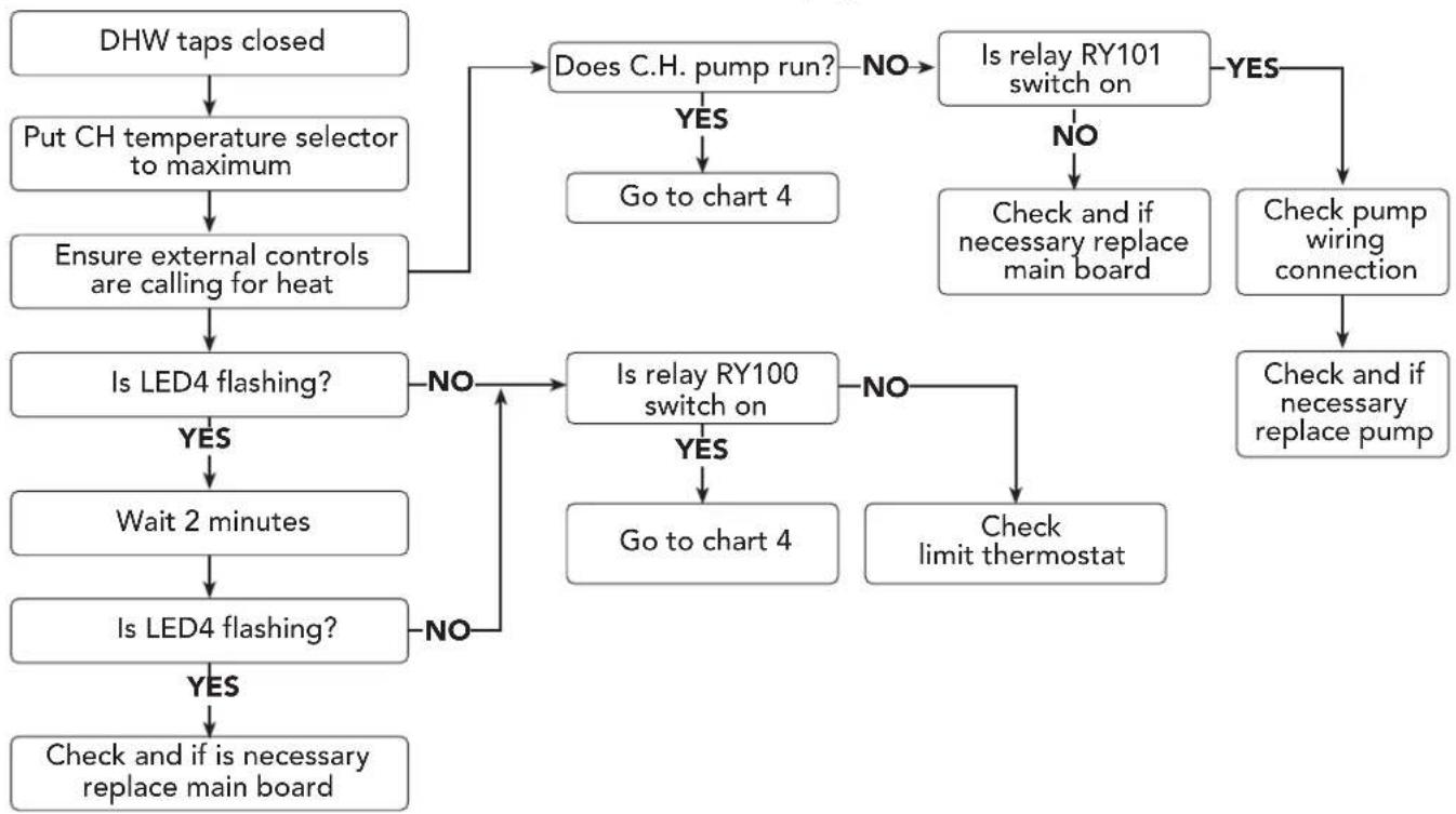
flowchart
graph TD
    A["DHW taps closed"] --> B["Put CH temperature selector to maximum"]
    B --> C["Ensure external controls are calling for heat"]
    C --> D{Is LED4 flashing?}
    D -->|YES| E["Wait 2 minutes"]
    D -->|NO| F{Is relay RY100 switch on}
    F -->|YES| G["Go to chart 4"]
    F -->|NO| H{Is relay RY101 switch on}
    H -->|YES| I["Check pump wiring connection"]
    H -->|NO| J["Check limit thermostat"]
    E --> K{Does C.H. pump run?}
    K -->|YES| L["Go to chart 4"]
    K -->|NO| M{Is relay RY101 switch on}
    M -->|YES| N["Check and if necessary replace main board"]
    M -->|NO| O{Is relay RY100 switch on}
    O -->|YES| P["Go to chart 4"]
    O -->|NO| Q{Check and if necessary replace pump}
    Q --> R["Check and if necessary replace main board"]

flowchart
graph TD
    A["Check fan/fl ue gas system"] --> B{Does fan run?}
    B -->|NO| C["Is relay RY100 switch ON?"]
    B -->|YES| D{Is air pressure switch activated?}
    D -->|NO| E["Differential air pressure across the air pressure switch is greater than 180 Pascal?"]
    D -->|YES| F["Go to chart 5"]
    C -->|NO| G["Go to charts 2-3"]
    C -->|YES| H{Is 230V present across fan terminals?}
    H -->|NO| I["Check air pressure switch wiring connection in N.O."]
    H -->|YES| J["Check and if necessary replace fan"]
    I -->|NO| K["Check and if necessary replace air pressure switch"]
    I -->|YES| L["Check and clean fan"]
    J --> M["Check flue and air intake are correct and clean"]
    M --> N["Check Venturi and air pressure switch tubes are clean"]
    N --> O["Check restrictor is correct"]
Chart 5 Check D.H.W. and C.H. modulation
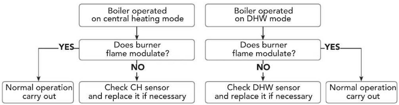
flowchart
graph TD
    A["Boiler operated on central heating mode"] --> B{Does burner flame modulate?}
    B -->|YES| C["Normal operation carry out"]
    B -->|NO| D["Check CH sensor and replace it if necessary"]
    E["Boiler operated on DHW mode"] --> F{Does burner flame modulate?}
    F -->|YES| G["Normal operation carry out"]
    F -->|NO| H["Check DHW sensor and replace it if necessary"]
Chart 6 Check ignition system

flowchart
graph TD
    A["Is LED1 light on? Does sparking start at burner?"] -->|YES| B["Does burner light?"]
    A -->|NO| C["Is LED2 on without the boiler sparking"]
    C -->|YES| D["Go to chart 5"]
    C -->|YES| E["Re-check air pressure switch"]
    B -->|NO| F["Is LED2 on after 10 seconds?"]
    F -->|YES| G["Reset lockout"]
    F -->|YES| H["Check and if necessary replace P.C.B."]
    G --> I["Does burner light now?"]
    I -->|NO| J["Is flame present before lockout condition?"]
    I -->|YES| K["Adjust with P4 ignition burner pressure"]
    K --> L["Check and if necessary clean burner"]
    L --> M["Check and if necessary clean injectors"]
    M --> N["Check and if necessary clean flame electrode"]
    N --> O["Check right position of spark electrode"]
    O --> P["Check wires"]
    C --> Q["Check and if necessary replace safety thermostat"]
    Q --> R["Check electrodes and leads for damage and correct connection"]
    R --> S["Check and if necessary replace P.C.B."]
    S --> T["Check gas supply is live and purged"]
    T --> U["Check and if necessary replace gas valve"]
9. ELECTRICAL AND FUNCTIONAL SCHEME
9.01 Main components layout on electronic boards
| Potentiometer adjustment |
| P1 = Central heating flow temperature adjustment |
| P2 = Domestic hot water temperature adjustment |
| P3 = Central heating flow output adjustment |
| P4 = Ignition gas pressure adjustment |
| P5 = Minimum adjustment pressure |

Fig. 35
| JP01 ON = Delay between shutdown and re-ignition disabledJP01 OFF = Delay between shutdown and re-ignition enabled | Temp. sensor NTC (34) (42) | temp. | Ohm | |
| 10 °C | 20 | kOhm | ||
| 25 °C | 10 | kOhm | ||
| 60 °C | 2,5 | kOhm | ||
| 80 °C | 1,25 | kOhm | ||
| JP02:Jumper on for natural gasJumper on for LPG | ||||
| JP03 ON = Max temperature D.H.W. 62°CJP03 OFF= Max temperature D.H.W. 55°C (standard) | ||||
9.02 General wiring diagram
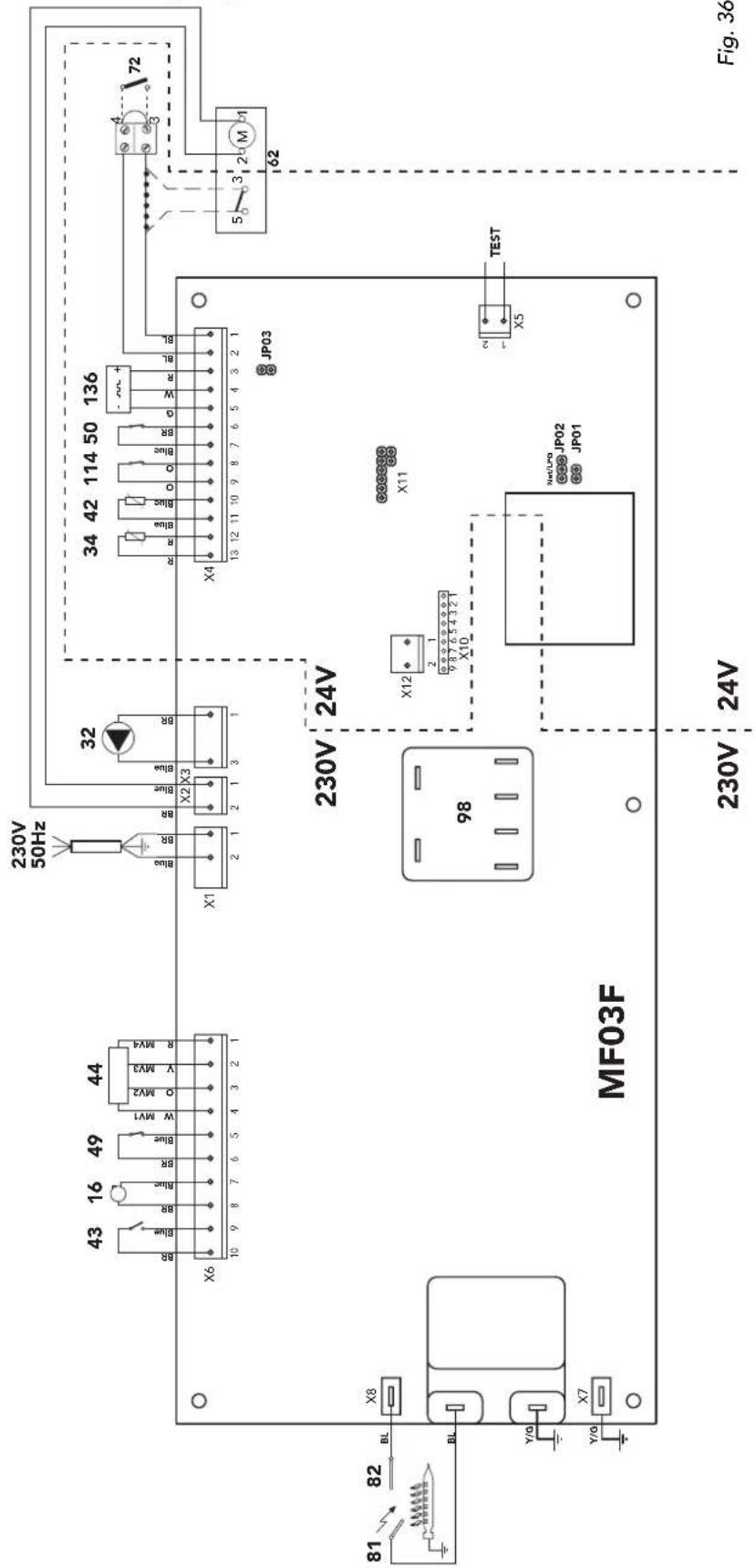
| Key | |||||
| 16 | Fan | 81 | Ignition electrode | Key | |
| 32 | Central heating pump | 82 | Sensor electrode | BR | Brown |
| 34 | Central heating flow temperature sensor | 98 | Off/On/Reset switch | BLUE | Blue |
| 42 | Domestic hot water flow temperature sensor | 114 | Low water pressure switch | BL | Black |
| 43 | Air pressure switch | 136 | Flow meter | W | White |
| 44 | Gas valve | O | Orange | ||
| 49 | Safety thermostat | G | Green | ||
| 50 | Central heating limit thermostat | R | Red | ||
| 62 | Time clock (option) | V | Violet | ||
| 72 | Room thermostat | ||||
10. USER INSTRUCTIONS

Fig. 37
| LED | ||
| 1 | Burner on indicator | |
| 2 | Boiler shut down warning | |
| 3 | Domestic hot water circuit on | |
| 4 | Central heating stand-by (Flashing light)Central heating circuit on (Permanent light) | |
| 5 | Insufficient pressure in central heating system (Flashing light)Electric power supply (Permanent light) | |
| KEY | DESCRIPTION |
| A | Switch OFF/ON/RESET |
| B | Central heating flow temperature regulation |
| C | D.H.W. temperature regulation |
| D | Water pressure gauge |
| E | Time clock (option) |
The boiler is designed for use with two types of gas: natural gas NG or propane (LPG). The type of gas can be selected when purchasing the boiler or the appliance can be converted later on site by a competent person. It operates with technologically advanced systems such as electronic control, safety and control devices.
The boiler is fitted with automatic electronic ignition so there is no pilot to worry about.
Pull down cover to reveal control facia panel.
Make sure that the gas, water and electricity supplies to the boiler are turned on.
The boiler pressure gauge (D) should read at least 1 bar.
Low pressure will be indicated by flashing light in the middle of the facia illuminating ( △ ).
Hot Water Only - "SUMMER" ()
To obtain hot water only from the boiler, turn switch (A) to the on position. The top green light on the left side of the control panel is illuminated (power on ).
Turn the temperature regulator (B) to the ⚙ position. Open a hot water tap, green light (tap symbol) comes on, fan starts and burner will light. Indicated by fl ame symbol, green light coming on. The temperature of the hot water can be adjusted by turning the hot water thermostat (C) clockwise to increase and anti-clockwise to decrease the water temperature.
Heating and Hot Water - "WINTER" ( ✉ )
To obtain heating from the boiler, turn the temperature regulator (B) clockwise to the maximum position, ensure that any other heating controls e.g. room thermostats, clock etc. are in the on position.
The boiler may be in heating delay of three minutes as indicated by the red light (egg timer symbol) on the left of the facia panel. When this light goes out the green light (radiator symbol) will come on. The fan and pump will run and the burner will light indicated by the green flame symbol light. Adjust the temperature regulator to the desired setting. (In winter do not run boiler below 50°C). If a hot water tap is opened whilst the boiler is running for heating the pump will stop, suspending the heating phase and the boiler will give priority to hot water production. When the tap is closed the boiler will go into a three minute delay cycle before resuming for heating.
Boiler lock out
In the event of the red lockout light (1) coming on, the on/off/reset switch (A) should be turned clockwise against the spring tension to the reset position and released (this will put the boiler into three minute delay if in the heating mode). If the lockout light (1) illuminates repeatedly, contact an approved Férroli service engineer.
Frost Protection
In cold weather the boiler may appear to run when there is no demand for heating (i.e. clocks or room thermostats turned off). This is due to the central heating sensor going into frost protection mode. Once the boiler has reached 14^ C or more it will close down until either the temperature again falls below 7^ C or the clock or room thermostat is turned on.
For this reason we recommend that the electricity to the boiler is left turned on. If you wish to turn off the electricity to the boiler in winter you should drain completely the heating and hot water circuits.
Cleaning
The casing requires no special cleaning, a wipe with a soft duster or damp cloth will suffice.
Maintenance
Férroli recommend that the appliance is serviced at least once every twelve months by a competent engineer.
Gas Supply
It is the law that all gas appliances are installed and serviced by a competent person in accordance with the Gas Safety Regulations (Installation & Use) 1996, and the manufacturers instructions. Failure to observe these requirements may lead to prosecution.
Electrical Supply
WARNING - This appliance must be earthed.
The electrical wiring must be carried out by a competent electrician.
The colours of the wires in the mains lead of this appliance may not correspond with the coloured markings identifying the terminal in the plug. Therefore, proceed as follows:
The wire coloured green and yellow must be connected to the terminal in the plug marked with either the letter E or by the earth symbol or coloured green or green and yellow. The wire coloured blue must be connected to the terminal marked either with the letter N or coloured black. The wire coloured brown must be connected to the terminal marked either with the letter L or coloured red.
MINIMUM CLEARANCE
The minimum clearance around the appliance should be as follows:
Sides 5mm
Front 600mm
Below 200mm
Above 100mm
Time Clock
A 24 hour time clock is fitted to the boiler to control the central heating, this will come into operation when the selector switch is turned to the position marked "heating timed and hot water".

A Slide switch: set clock - auto - set programme
B Display. Symbol ⚙ in Display = Timer ON
P Select programme ON/OFF 1.....8
D Push buttons Time + Time -
E Override: Boiler will switch ON if boiler is OFF; and OFF if is ON
F I=Heating continuous - AUTO=Heating timed - O=Heating disabled
R Reset (with pencil) only with switch A in set clock position
To set time of day
- Slide switch (A) to left position
- Using button + and - adjust until the correct time is shown on display (B).
Pre Set Programmes. The timer is pre programmed with 3 ON and 3 OFF times.
6:30 - 8:30 12:00 - 12:00 16:30 : 22:30
If these are suitable no programming is required and the slide switch (A) can be moved to the Auto position and the central heating will be ON for these periods. (12:00 - 12:00 will not switch on the boiler)
To Set Own ON and OFF times. Symbol ☐ in Display = ON time
- Slide switch (A) to right position (P)
Display
b:30 1
- Press button (P)
Display
8:30 a
- Press button (P)
Display
12:00 3°
- Press button (P)
Display
12:00 4
- Press button (P)
Display
16:30 5
- Press button (P)
Display
22:30 b
- The timer can be programmed with up to 8 ON and 8 OFF times by repeating the above procedure.
1.1 Use buttons + and - to set 1st ON time eg. 6:00
Display 6:00 1
2.1 Use buttons + and - to set OFF time, eg. 9:00
Display 9:00 2
3.1 Use button + and - to set 2nd ON time, eg. 12:30
Display 12:30 3
4.1 Use button + and - to set 2nd OFF time eg. 14:00
Display 14:00 4
5.1 Use button + and - to set 3rd ON time, eg. 16:00
Display 16:00 5
6.1 Use button + and - to set 3rd OFF time eg. 23:30
Display 23:30 b
- On completion of programming slide switch (A) to Auto position, the time of day will be displayed and the central heating will switch ON and OFF according to the programme set.
Over ride
By pressing the over ride button (E) the timer programme is over ridden ie, if programme is in OFF time it will come ON and if in ON time will go OFF. The timer will revert back to it set programme on reaching the next ON or OFF time. When the programme is on over ride the sign will be shown in the display window (B).
Reset Button
By the use of a pencil the reset button can be pushed (R). This will clear all programmes apart from those factory pre set.
Reset is only possible with switch (A) in set Clock position!
Should you require help with any difficulties call our Technical Service Helpline on 08707 282 885
Phone numbers:
Installer
Service Engineer ____
BECAUSE OF OUR CONSTANT ENDEAVOUR FOR IMPROVEMENT DETAILS MAY VARY SLIGHTLY FROM THOSE QUOTED IN THESE INSTRUCTIONS.

ALL SPECIFICATIONS SUBJECT TO CHANGE
Please note - to avoid incurring unnecessary expense, in the event of a boiler shut down, check this in not caused by lack of electricity supply, gas supply or low water pressure before calling our Customer Service Helpline.
Lichfield Road, Branston Industrial Estate, Burton Upon Trent, Staffordshire DE14 3HD Tel. 08707 282 885 - Fax 08707 282 886
- IMPORTANT
- CE MARK
- Year 2000 Compliance Declaration
- INDEX
- DESCRIPTION
- Introduction
- Instructions and regulations
- C.O.S.H.H.
- Related Documents
- TECHNICAL AND DIMENSIONAL CHARACTERISTICS
- Technical information
- Key
- Central heating adjustment (not normally required)
- Pump characteristics
- Pump performance curve Grundfos UPS 15-50
- SIZING OF ADDITIONAL EX PANSION VESSELS:
- Note:
- Pressure loss diagram
- INSTALLATION DETAILS
- Location of Boiler
- Air Supply
- Flue System
- Gas Supply
- Water System
- Central Heating
- Make Up Water
- Domestic Hot Water
- CLEARANCES:
- Drilling Template (Top Flue Application)
- Restrictor
- Choice of restrictor:
- Top Outlet Concentric Flue Connection
- Vertical concentric connection
- Horizontal concentric connection
- Notes on concentric horizontal installation
- Maximum concentric flue length
- Top Outlet: Two Pipe Flue System
- Two pipe connection
- IMPORTANT:
- Notes on two pipe system installation:
- Two pipe fl ue system
- To determine the maximum length of flue and air pipe permissible.
- Calculation Routine
- Attention:
- Example of other installation with two pipe systems
- Connecting the central heating and domestic hot water circuits
- Boiler water characteristics
- Filling
- Gas connection
- Electrical connection
- Applying mains voltage to the switch contacts will irreparably damage the circuit board.
- Differential air pressure switch (fig. 2 - part 43)
- Checks
- Installing a room thermostat (72) (fig. 21b)
- Time clock fixing (optional)
- COMMISSIONING AND TESTING
- Checks to be carried out before starting up for the first time
- Starting up the boiler
- Shutting down
- Checks and controls after first start-up
- ADJUSTMENT AND GAS CONVERSION
- Adjusting the pressure and flow rate to the main burner
- Adjusting minimum and maximum pressure Honeywell V K4105G gas valve
- Adjustment potentiometers
- Adjusting maximum output for central heating system (fi g. 23)
- N.B. - when carrying out this operation ensure that the boiler thermostat is set to maximum otherwise the adjustment will not be accurate.
- Adjusting central heating flow temperature
- Adjusting room temperature (when a room thermostat is fitted)
- Adjusting the central heating flow t by varying pump flow-head
- Adjusting central heating system pressure
- N.B.- To avoid incurring unnecessary expense, in the event of boiler shut down, check that this is not caused by a lack of electricity or gas, or low water pressure before calling the Customer Technical Service Helpline.
- Gas conversion
- Note: After converting the boiler from natural gas to liquid gas, fit the orange plate in the conversion kit near the data plate.
- MAINTENANCE AND CLEANING
- Annual Servicing
- Cleaning the boiler and burner
- Servicing procedure
- Flue Gas Analysis
- REPLACEMENT OF PARTS
- Initial procedure
- Final procedure
- To lower the control panel (fig. 25)
- Gas valve (fig. 26)
- Air pressure switch (fi g. 27)
- D.H.W. temperature sensor or Central Heating Temperature Sensor (fi g. 28)
- Water Pressure Switch (fig. 28)
- Safety Valve (fig. 28)
- Removal of burner (fi g. 29)
- Injectors (fig. 29)
- Removal of fan (fig. 30)
- Limit thermostat, or overheat cut off thermostat (fig. 30)
- Spark or flame detection electrode
- D.H.W. flowmeter
- Observe the correct position of components as shown in fig. 32b
- Pump (fi g. 33)
- Replacement of pump head
- Replacement of pump body (fig. 33)
- Removal of heat exchanger
- FAULT FINDING
- Operating Sequence
- Central Heating Mode
- Domestic Hot Water Mode
- MF03 PCB
- Boiler will not light for D.H.W.
- Boiler will not light for C.H.
- Boiler will not light for D.H.W. or C.H.
- Temperature sensors (thermistors)
- Limit thermostats
- Ignition PCB
- Main printed circuit board
- Air pressure switch
- General test and fault finding
- ELECTRICAL AND FUNCTIONAL SCHEME
- Main components layout on electronic boards
- USER INSTRUCTIONS
- Hot Water Only - "SUMMER" ()
- Heating and Hot Water - "WINTER" ( ✉ )
- Boiler lock out
- Frost Protection
- Cleaning
- Maintenance
- Electrical Supply
- WARNING - This appliance must be earthed.
- MINIMUM CLEARANCE
- Time Clock
- To set time of day
- To Set Own ON and OFF times. Symbol ☐ in Display = ON time
- Over ride
- Reset Button
- Should you require help with any difficulties call our Technical Service Helpline on 08707 282 885
Brand : FERROLI
Model : Domina 102
Category : Central Heating Boiler