
CM 7MC - Milling machine HITACHI - Free user manual and instructions
Find the device manual for free CM 7MC HITACHI in PDF.

| Product Type | Milling Machine |
| Brand | Hitachi |
| Model | CM 7MC |
| Motor Power | 750 W (1 HP) |
| Spindle Speed Range | 100 – 3000 RPM (variable) |
| Table Size | 450 x 140 mm |
| X-Axis Travel | 240 mm |
| Y-Axis Travel | 120 mm |
| Z-Axis Travel (Quill) | 60 mm |
| Spindle Taper | MT2 (Morse Taper 2) |
| Max. Drilling Capacity (Steel) | 10 mm |
| Max. Milling Capacity (Steel) | 6 mm |
| Weight | 32 kg |
| Power Supply | 220-240 V, 50/60 Hz, single phase |
| Main Functions | Drilling, milling, tapping, slotting, engraving |
| Coolant System | Optional coolant pump (not included) |
| Digital Readout | Optional 3-axis DRO (not included) |
| Chuck Type | Keyless drill chuck (capacity 1-10 mm) |
| Safety Features | Emergency stop button, spindle guard, overload protection |
| Maintenance | Regular lubrication of ways and spindle, check belt tension |
| Spare Parts Availability | Replacement motor brushes, belt, bearings, collets, and chuck |
| Repairability | Modular design, user-replaceable components with basic tools |
| Included Accessories | Drill chuck, chuck key, clamping kit, hex wrenches |
| Warranty | 2 years limited warranty (check local terms) |
Frequently Asked Questions - CM 7MC HITACHI
User questions about CM 7MC HITACHI
0 question about this device. Answer the ones you know or ask your own.
Ask a new question about this device
Download the instructions for your Milling machine in PDF format for free! Find your manual CM 7MC - HITACHI and take your electronic device back in hand. On this page are published all the documents necessary for the use of your device. CM 7MC by HITACHI.
USER MANUAL CM 7MC HITACHI
natural_image
Line drawing of a mechanical power saw with lever and handle (no text or symbols)Read through carefully and understand these instructions before use.

Bruksanvisning
Brugsanvisning
Bruksanvisning
Käyttöohjeet
Handling Instructions
7
8
9
CM7MR • CM7MRU
CM7MC
10
| Svenska Dansk Norsk | |||
| 1 | Borstskydd | Børstedæksel | Børstedeksel |
| 2 | Låsknapp | Låseknap | Låsknappe |
| 3 | Strömbrytare | Afbryder | Bryter |
| 4 | Vakuumkoppling | Vakuumkobling | Vakum kobling |
| 5 | Sidohandtag | Sidehåndtag | Side håndtak |
| 6 | Dammskydd | Støvdæksel | Støvdeksel |
| 7 | Knoppbult | Skruehåndtag | Bolt |
| 8 | Dammskydd | Støvafskærmning | Støv vern |
| 9 | Tryckknapp (Spindellås) | Trykknap (Spindellås) | Trykknapp (Spindellås) |
| 10 | 22 mm Nyckel | 22 mm Nøgle | 22 mm Nøkkel |
| 11 | M14 bult | M14-bolt | M14 bolt |
| 12 | Diamanthjul | Diamantskive | Diamantskive |
| 13 | Bladbricka | Spændeskive til klinge | Underlagsskive for blad |
| 14 | Bladdistans (3) | Klingeafstandsskive (3) | Underlagsplater for blad (3) |
| 15 | Bladdistans (5) (8 delar) | Klingeafstandsskive (5) (8 stk.) | Underlagsplater for blad (5) (8 stykk) |
| 16 | Drivaxel | Drivaksel | Drivaksel |
| 17 | Sågdjup | Skæredybde | Skjæredybde |
| 18 | Dammuppsamlingsslang | Støvopsamlingsslange | Støv oppsamlingsrør |
| 19 | Såglinje | Skærelinie | Skjærelinje |
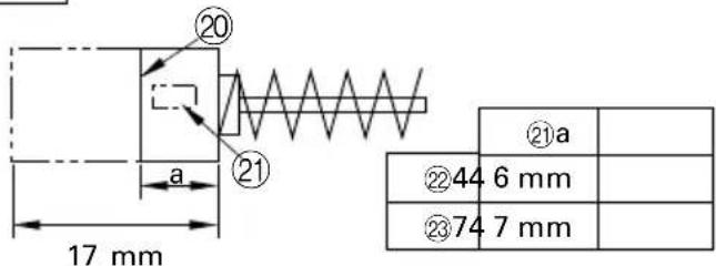
| 20 | Avnötningsgräns | Slidgrænse | Slitasjegrense |
| 21 | Nr. av kolsborste | Kulnummer | Kullbørstens Nr. |
| 22 | Vanlig kolborste | Almindelig kulbørste | Vanlig kullbørste |
| 23 | Automatisk, motoravstängande kolborste | Auto-stop kulbørste | Kullbørste som stopper motoren automatisk |
| 24 | Fjäder | Fjeder | Fjær |
| 25 | Borsthållare | Børsteholder | Børsteholder |
| CM7MR • CM7MRU | |||
| 1Kol | Ihatt Kuldæksel Børstedeksel | ||
VEDLIKEHOLD OG KONTROLL
Read all safety warnings and all instructions.
Failure to follow the warnings and instructions may result in electric shock, fire and/or serious injury.
Save all warnings and instructions for future reference.
The term "power tool" in the warnings refers to your mains-operated (corded) power tool or battery-operated (cordless) power tool.
1) Work area safety
a) Keep work area clean and well lit.
Cluttered or dark areas invite accidents.
b) Do not operate power tools in explosive atmospheres, such as in the presence of flammable liquids, gases or dust.
Power tools create sparks which may ignite the dust or fumes.
c) Keep children and bystanders away while operating a power tool.
Distractions can cause you to lose control.
2) Electrical safety
a) Power tool plugs must match the outlet.
Never modify the plug in any way.
Do not use any adapter plugs with earthed (grounded) power tools.
Unmodified plugs and matching outlets will reduce risk of electric shock.
b) Avoid body contact with earthed or grounded surfaces, such as pipes, radiators, ranges and refrigerators.
There is an increased risk of electric shock if your body is earthed or grounded.
c) Do not expose power tools to rain or wet conditions.
Water entering a power tool will increase the risk of electric shock.
d) Do not abuse the cord. Never use the cord for carrying, pulling or unplugging the power tool. Keep cord away from heat, oil, sharp edges or moving parts.
Damaged or entangled cords increase the risk of electric shock.
e) When operating a power tool outdoors, use an extension cord suitable for outdoor use.
Use of a cord suitable for outdoor use reduces the risk of electric shock.
f) If operating a power tool in a damp location is unavoidable, use a residual current device (RCD) protected supply.
Use of an RCD reduces the risk of electric shock.
3) Personal safety
a) Stay alert, watch what you are doing and use common sense when operating a power tool. Do not use a power tool while you are tired or under the influence of drugs, alcohol or medication.
A moment of inattention while operating power tools may result in serious personal injury.
b) Use personal protective equipment. Always wear eye protection.
Protective equipment such as dust mask, non-skid safety shoes, hard hat, or hearing protection used for appropriate conditions will reduce personal injuries.
c) Prevent unintentional starting. Ensure the switch is in the off-position before connecting to power source and/or battery pack, picking up or carrying the tool.
Carrying power tools with your finger on the switch or energising power tools that have the switch on invites accidents.
d) Remove any adjusting key or wrench before turning the power tool on.
A wrench or a key left attached to a rotating part of the power tool may result in personal injury.
e) Do not overreach. Keep proper footing and balance at all times.
This enables better control of the power tool in unexpected situations.
f) Dress properly. Do not wear loose clothing or jewellery. Keep your hair, clothing and gloves away from moving parts.
Loose clothes, jewellery or long hair can be caught in moving parts.
g) If devices are provided for the connection of dust extraction and collection facilities, ensure these are connected and properly used.
Use of dust collection can reduce dust related hazards.
4) Power tool use and care
a) Do not force the power tool. Use the correct power tool for your application.
The correct power tool will do the job better and safer at the rate for which it was designed.
b) Do not use the power tool if the switch does not turn it on and off.
Any power tool that cannot be controlled with the switch is dangerous and must be repaired.
c) Disconnect the plug from the power source and/or the battery pack from the power tool before making any adjustments, changing accessories, or storing power tools.
Such preventive safety measures reduce the risk of starting the power tool accidentally.
d) Store idle power tools out of the reach of children and do not allow persons unfamiliar with the power tool or these instructions to operate the power tool.
Power tools are dangerous in the hands of untrained users.
e) Maintain power tools. Check for misalignment or binding of moving parts, breakage of parts and any other condition that may affect the power tools operation.
If damaged, have the power tool repaired before use.
Many accidents are caused by poorly maintained power tools.
f) Keep cutting tools sharp and clean.
Properly maintained cutting tools with sharp cutting edges are less likely to bind and are easier to control.
g) Use the power tool, accessories and tool bits etc. in accordance with these instructions, taking into account the working conditions and the work to be performed.
Use of the power tool for operations different from those intended could result in a hazardous situation.
5) Service
a) Have your power tool serviced by a qualified repair person using only identical replacement parts. This will ensure that the safety of the power tool is maintained.
PRECAUTION
Keep children and infirm persons away.
When not in use, tools should be stored out of reach of children and infirm persons.
WALL CHASER SAFETY WARNINGS
a) Read all safety warnings, instructions, illustrations and specifications provided with this power tool. Failure to follow all instructions listed below may result in electric shock, fire and/or serious injury.
b) Always use guard provided with the tool. The guard must be securely attached to the power tool and positioned for maximum safety, so the least amount of wheel is exposed towards the operator. Position yourself and bystanders away form the plane of the rotating wheel.
The guard helps to protect operator from broken wheel fragments and accidental contact with wheel.
c) Use only flat reinforced or diamond cut-off wheels for your power tool.
Just because an accessory can be attached to your power tool, it does not assure safe operation.
d) The rated speed of the wheel must be at least equal to the maximum speed marked on the power tool. Wheels running faster than their rated speed can break and fly apart.
e) Wheels must be used only for recommended applications. For example: do not grind with the side of cut-off wheel.
Abrasive cut-off wheels are intended for peripheral grinding, side forces applied to these wheels may cause them to shatter.
f) Always use undamaged wheel flanges that are of correct diameter for your selected wheel.
Proper wheel flanges support the wheel thus reducing the possibility of wheel breakage.
g) Do not use worn down flat reinforced wheels from larger power tools.
Wheels intended for a larger power tool are not suitable for the higher speed of a smaller tool and may burst.
h) The outside diameter and the thickness of your wheel must be within the capacity rating of your power tool.
Incorrectly sized wheels cannot be adequately guarded or controlled.
i) The arbour size of wheels and flanges must properly fit the spindle of the power tool.
Wheels and flanges with arbour holes that do not match the mounting hardware of the power tool will run out of balance, vibrate excessively and may cause loss of control.
j) Do not use damaged wheels. Before each use, inspect the wheels for chips and cracks. If power tool or wheel is dropped, inspect for damage or install an undamaged wheel. After inspecting and installing the wheel, position yourself and bystanders away from the plane of the rotating wheel and run the power tool at maximum no load speed for one minute.
Damaged wheels will normally break apart during this test time.
k) Wear personal protective equipment. Depending on application, use face shield, safety goggles or safety glasses. As appropriate, wear dust mask, hearing protectors, gloves and shop apron capable of stopping small abrasive or workpiece fragments.
The eye protection must be capable of stopping flying debris generated by various operations. The dust mask or respirator must be capable of filtrating particles generated by your operation. Prolonged exposure to high intensity noise may cause hearing loss.
I) Keep bystanders a safe distance away from work area. Anyone entering the work area must wear personal protective equipment.
Fragments of wheel or of a broken accessory may fly away and cause injury beyond immediate area of operation.
m) Hold power tool by insulated gripping surfaces only, when performing an operation where the wheel may contact hidden wiring or its own cord.
Wheel contacting a "live" wire may make exposed metal parts of the power tool "live" and shock the operator.
n) Position the cord clear of the spinning accessory. If you lose control, the cord may be cut or snagged and your hand or arm may be pulled into the spinning wheel.
o) Never lay the power tool down until the wheel has come to a complete stop.
The spinning wheel may grab the surface and pull the power tool out of your control.
p) Do not run the power tool while carrying it at your side.
Accidental contact with the spinning wheel could snag your clothing, pulling the wheel into your body.
q) Regularly clean the power tool's air vents.
The motor's fan will draw the dust inside the housing and excessive accumulation of powdered metal may cause electrical hazards.
r) Do not operate the power tool near flammable materials.
Sparks could ignite these materials.
s) Do not use wheels that require liquid coolants.
Using water or other liquid coolants may result in electrocution or shock.
KICKBACK AND RELATED WARNINGS
Kickback is a sudden reaction to a pinched or snagged rotating wheel. Pinching or snagging causes rapid stalling of the rotating wheel which in turn causes the uncontrolled power tool to be forced in the direction opposite of the wheel's rotation at the point of the binding.
a) Maintain a firm grip on the power tool and position your body and arm to allow you to resist kickback forces. Always use auxiliary handle, if provided, for maximum control over kickback or torque reaction during start-up.
The operator can control torque reactions or kickback forces, if proper precautions are taken.
b) Never place your hand near the rotating wheel. Wheel may kickback over your hand.
c) Do not position your body in line with and behind the rotating wheel.
Kickback will propel the tool in direction opposite to the wheel's movement at the point of snagging.
d) Use special care when working corners, sharp edges etc. Avoid bouncing and snagging the wheel.
Corners, sharp edges or bouncing have a tendency to snag the rotating wheel and cause loss of control or kickback.
e) Do not attach a saw chain woodcarving blade or toothed saw blade.
Such blades create frequent kickback and loss of control.
f) Do not "jam" the wheel or apply excessive pressure. Do not attempt to make an excessive depth of cut.
Overstressing the wheel increases the loading and susceptibility to twisting or blinding of the wheel in the cut and the possibility of kickback or wheel breakage.
g) When wheel is binding or when interrupting a cut for any reason, switch off the power tool and hold the power tool motionless until the wheel comes to a complete stop. Never attempt to remove the wheel from the cut while the wheel is in motion otherwise kickback may occur.
Investigate and take corrective action to eliminate the cause of wheel binding.
h) Do not restart the cutting operation in the workpiece. Let the wheel reach full speed and carefully re-enter the cut.
The wheel may bind, walk up or kickback if the power tool is restarted in the workpiece.
i) Support panels or any oversized workpiece to minimize the risk of wheel pinching and kickback.
Large workpieces tend to sag under their own weight. Supports must be placed under the workpiece near the line of cut and near the edge of the workpiece on both sides of the wheel.
j) Use extra caution when making a "pocket cut" into existing walls or other blind areas.
The protruding wheel may cut gas or water pipes, electrical wiring or objects that can cause kickback.
PRECAUTION ON USING WALL CHASER
-
Never operate these power tools without wheel guards attached.
-
Do not over-reach when operating the wall chaser.
-
Check that the speed marked on the diamond wheels or cutting wheel is equal to or greater than the rated speed of the wall chaser.
-
Use only specified diamond wheels and cutting wheels.
-
Diamond wheels and cutting wheels shall be stored and handled with care in accordance with manufacturer's instructions.
-
Inspect the diamond wheel or cutting wheel before use, do not use chipped, cracked or otherwise defective products.
-
Always hold the body handle and top handle of the power tool firmly. Otherwise the counter force produced may result in inaccurate and even dangerous operation.
-
Do not use separate reducing bushings or adapters to adapt cutting wheels with a bore other than 22.2 mm.
-
Do not use this machine to cut asbestos.
-
The diamond wheels continue to rotate after the tool is switched off.
-
Wear a dust mask Do not inhale the harmful dusts generated in cutting operation. The dust can endanger the health of yourself and bystanders.
SPECIFICATIONS
| Model CM7MR CM7MRU CM7MC | |||
| Voltage (by areas)*1 | (110 V, 230 V) ~ | ||
| Power input*1 | 2000 W, 2300 W | ||
| No-load speed 6600 min | -1 | ||
| Dimensions of diamond | Outer dia. 180 mmHole dia. 22.2 mmThickness 1.5 - 2 mm(Thickness of installation part.) | ||
| Max. cutting depth 35 mm | |||
| Max. cutting width 45 mm | |||
| Weight (without cord and diamond wheel) 7 | 9 kg 8.8 kg | ||
| Starting current limiter*2 | No Yes No | ||
*1 Be sure to check the nameplate on product as it is subject to change by areas.
*2 The starting current limiter produces the starting current to such an extent that a fuse (16 A, slow-blow) is not tripped.
STANDARD ACCESSORIES
(1) 22 mm Wrench .... 1
(2) Side handle 1
Standard accessories are subject to change without notice.
APPLICATION
Cutting slits in concrete, cement, brick or tiles. Slits can then be chipped with a separate tool to make grooves for laying plumber's piping or cable trunking.
PRIOR TO OPERATION
1. Power source
Ensure that the power source to be utilized conforms to the power requirements specified on the product nameplate.
2. Power switch
Ensure that the power switch is in the OFF position. If the plug is connected to a power receptacle while the power switch is in the ON position, the power tool will start operating immediately, which could cause a serious accident.
3. Extension cord
When the work area is removed from the power source, use an extension cord of sufficient thickness and rated capacity. The extension cord should be kept as short as practicable.
4. Checking and installing the diamond wheel
Check the diamond wheel is a specified one and is not cracked, broken or bent. Check the diamond wheel is installed securely. For installation, refer to "Installing/removing diamond wheel".
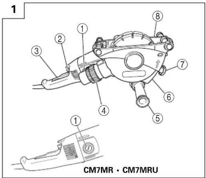
5. Dust collection cover (Fig. 1, Fig. 2)
The dust collection cover is a protective device to prevent injury should the diamond wheel shatter during operation. Ensure that the cover is properly fitted and fastened before commencing cutting operation.
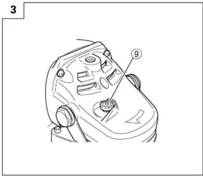
6. Spindle lock mechanisms
Confirm that the spindle lock is disengaged by pushing push button two or three times before switching the power tool on (See Fig. 3).
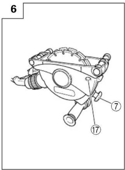
7. Cutting depth adjustment (Fig. 6)
After loosening the knob bolt (Fig. 1) the wall chaser can be sent to any desired depth between 0 mm and 35 mm according to the scale on the dust guard (Fig 6). Ensure that the knob bolt is fully tightened once cutting depth has been adjusted and set.
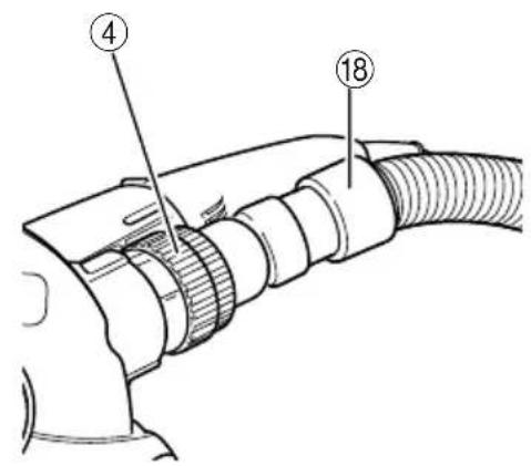
INSTALLING DUST COLLECTION HOSE
When cutting a material which generates cutting dust, use the dust collection hose as follows:
○Install the dust collector hose for the power tool. (Fig. 7)
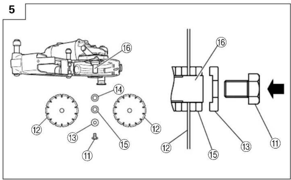
INSTALLING/REMOVING DIAMOND WHEEL
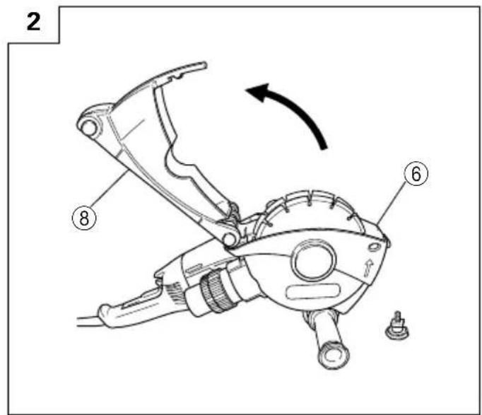
1. Removal (Fig. 1-5)
(1) Disconnect the machine from the power supply
(2) Place the machine on a level surface with the dust cover facing upwards.
(3) Remove the knob bolt at the front of the dust cover which secures the dust guard.
(4) Pivot the dust guard out and away from the dust cover.
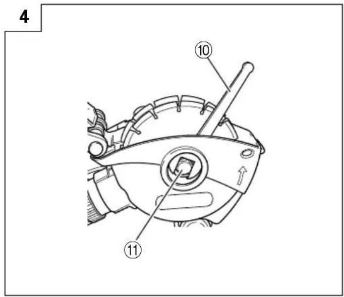
(5) Lock the drive shaft in place by pressing in the push button (spindle lock).
(6) While holding the push button in place, remove the diamond wheel retention M14 bolt using the 22 mm wrench supplied.
(7) Remove the blade spacers and diamond wheels from the drive shaft.
2. Installation (Fig. 1-6)
(1) Disconnect the machine from the power supply.
(2) Fit the blade spacer (3) onto the drive shaft.
(3) Place the first diamond wheel onto the drive shaft.
(4) Put the next blade spacer (5)/spacers onto the drive shaft in order to create the desired cutting width.
(5) Place the second diamond wheel onto the drive shaft.
(6) Fit the remaining spacer if not already applied.
(7) Fit the blade washer, ensuring that the concave side is facing toward the drive shaft.
(8) Secure the diamond wheel retention M14 bolt while holding the push button as before.
(9) Ensure that the diamond wheels are secure and that there is no lateral movement or rotation of the diamond wheels on the drive shaft.
(10) Secure the dust guard and lock in place at the required cutting depth by tightening the knob bolt.
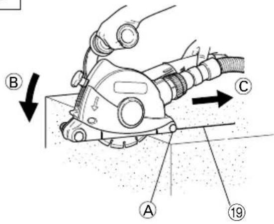
CUTTING
1. Cutting procedures (Fig. 8)
(1) Place part Ⓐ on the material to be cut, making sure that the diamond wheel is not touching the material.
(2) Switch on and slowly cut a slit in the direction of the arrow Ⓑ.
(3) Cut along the cutting line in the direction of the arrow Ⓒ.
2. Switch operation
Switch ON: Push the locking button forward and then press the switch lever. Switch OFF: Press and release the switch lever.
3. Precautions immediately after finishing operation
After switching off the machine, do not put it down until the depressed center wheel has come to a complete stop. Apart from avoiding serious accidents, this precaution will reduce the amount of dust and swarf sucked into the machine.
CAUTION
○Always check the diamond wheel before starting work. Never use a diamond wheel which is cracked, broken or bent.
○Do not apply water or coolant to the diamond wheel.
○Start cutting only when diamond wheel reaches its maximum speed.
○If the diamond wheel seizes or there is any abnormal noise, immediately turn the power off.
Never use the diamond wheel to cut zigzag or curved lines. Never use the side surface of the diamond wheel. Never use to perform inclination cutting.
○If excessive force is applied to the diamond wheel to make it align with the cutting line during cutting, this might not only overload the motor and cause burn damage but may also overheat the diamond wheel and shorten the service life.
- Secure the workpiece. A workpiece clamped with clamping devices or in a vice is held more securely than by hand.
○Take care not to allow the power cord to come into contact with the diamond wheel during operation.
○When the work is completed, turn the power off and disconnect the power plug from the receptacle.
MAINTENANCE AND INSPECTION
1. Inspection the diamond wheel
A worn diamond wheel overloads the motor and reduces working efficiency. Replace with a new one.
2. Diamond wheel clogging
The rate of wear of the diamond layer cutting edge will vary depending on the type of material being cut, the cutting speed, etc. In general, materials which produce granular cutting particles may scrape the bodying agent and hasten the wear of the diamond layer. On the other hand, materials which produce powdery cutting particles may cause clogging of the diamond layer which will reduce cutting efficiency. When clogging occurs, additional force applied in an attempt to increase cutting speed will sometime cause sparks to appear around the circumference of the diamond wheel. In such a case, stop using the cutter and carefully inspect the cutting edge by rubbing it with your fingers. If the diamond layer feels smooth (no roughness or abrasiveness), it is clogged with dust and must be "dressed". For thorough dressing, approximately 5 meters of slightly accelerated cutting at a depth of 10mm in a relative soft material which produces granular cutting particles (such as a cement block or brick) will restore the cutting effectiveness of the diamond layer and will extend the service life of the diamond wheel.
The diamond material is susceptible to high temperatures and will begin to deteriorate at approximately 600^ C. Higher temperatures will cause decomposition of the diamond material. Accordingly, it is important to perform “dressing” as soon as clogging or sparking occurs.
3. Inspecting the mounting screws
Regularly inspect all mounting screws and ensure that they are properly tightened. Should any of the screws be loose, retighten them immediately. Failure to do so could result in serious hazard.
4. Maintenance of the motor
The motor unit winding is the very "heart" of the power tool.
Exercise due care to ensure the winding does not become damaged and/or wet with oil or water.
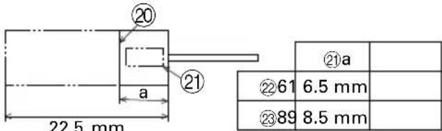
5. Inspecting the carbon brushes (Fig. 9)
The motor employs carbon brushes which are consumable parts.
When they become worn to or near the "wear limit", it could result in motor trouble. When an auto-stop carbon brush is equipped, the motor will stop automatically.
At that time, replace both carbon brushes with new ones which have the same carbon brush numbers shown in the figure. In addition, always keep carbon brushes clean and ensure that they slide freely within the brush holders.
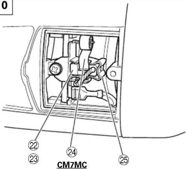
6. Replacing carbon brushes
CM7MC (Fig. 10)
(1) Loosen the D4 tapping screw retaining the brush cover and remove the brush cover.
(2) Use the auxiliary hexagonal wrench or small screwdriver to pull up the edge of the spring that is holding down the carbon brush. Remove the edge of the spring toward the outside of the brush holder.
(3) Remove the end of the pig-tail on the carbon brush from the terminal section of brush holder and then remove the carbon brush from the brush holder.
(1) Insert the end of the pig-tail of the carbon brush in the terminal section of brush holder.
(2) Insert the carbon brush in the brush holder.
(3) Use the auxiliary hexagonal wrench or small screwdriver to return the edge of the spring to the head of the carbon brush.
(4) Mount the brush cover and tighten the D4 tapping screw.
CM7MR • CM7MRU
Disassemble the brush cap with a slotted-head screwdriver. The carbon brush can then be easily removed.
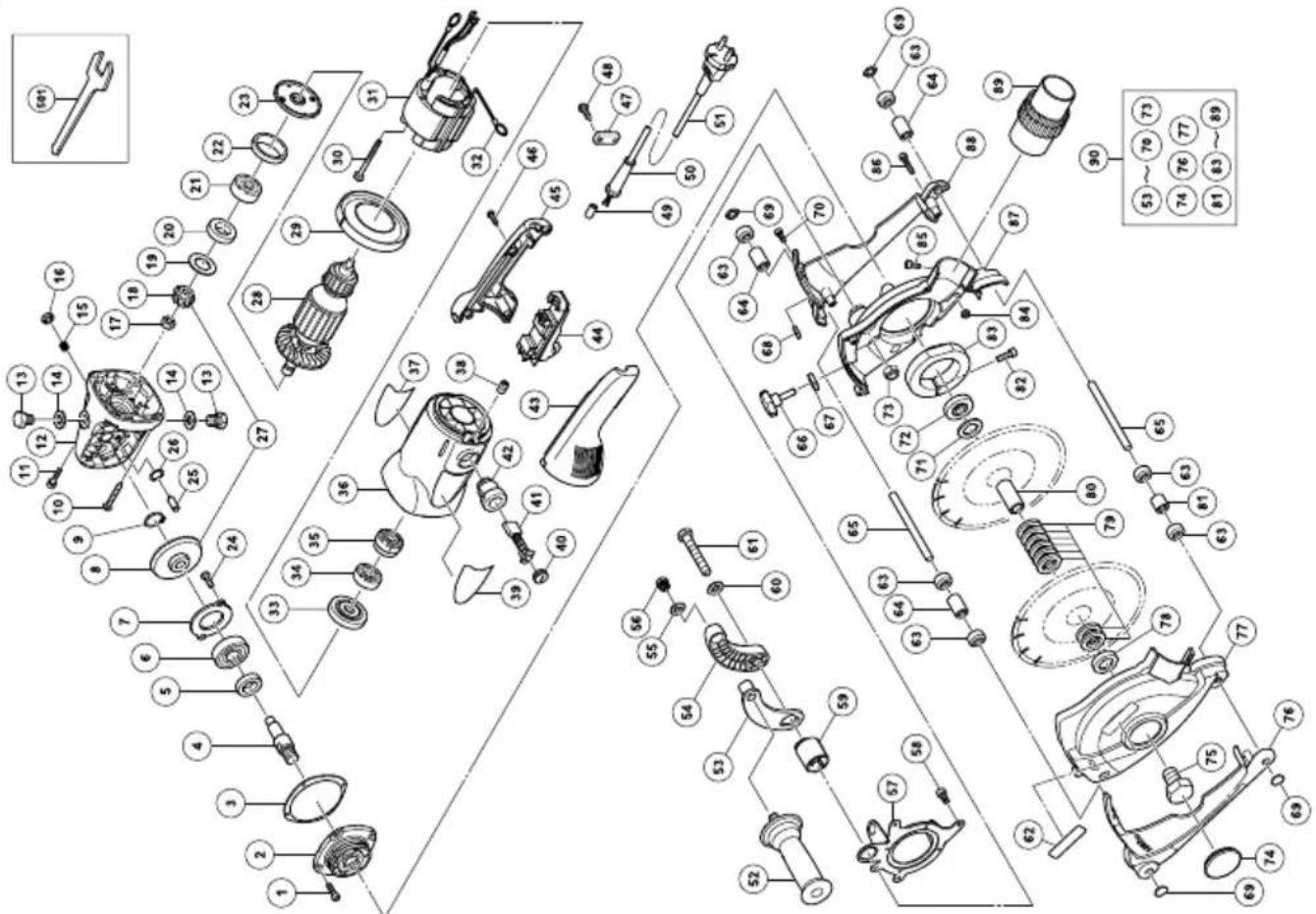
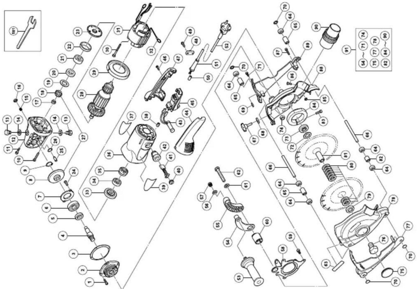
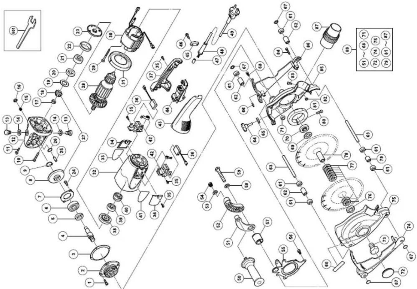
7. Service parts list
CAUTION
Repair, modification and inspection of Hitachi Power Tools must be carried out by a Hitachi Authorized Service Center.
This Parts List will be helpful if presented with the tool to the Hitachi Authorized Service Center when requesting repair or other maintenance.
In the operation and maintenance of power tools, the safety regulations and standards prescribed in each country must be observed.
MODIFICATIONS
Hitachi Power Tools are constantly being improved and modified to incorporate the latest technological advancements.
Accordingly, some parts may be changed without prior notice.
NOTE
Due to HITACHI's continuing program of research and development, the specifications herein are subject to change without prior notice.
Information concerning airborne noise and vibration
The measured values were determined according to EN60745 and declared in accordance with ISO 4871.
Measured A-weighted sound power level: 110 dB (A).
Measured A-weighted sound pressure level: 99 dB (A).
Uncertainty KpA: 3 dB (A).
Wear hearing protection.
Vibration total values (triax vector sum) determined according to EN60745.
Vibration emission value a_h = 7.4m / s^2
Uncertainty K = 1.5 m/s ^4
The declared vibration total value has been measured in accordance with a standard test method and may be used for comparing one tool with another.
It may also be used in a preliminary assessment of exposure.
WARNING
○The vibration emission during actual use of the power tool can differ from the declared total value depending on the ways in which the tool is used.
○Identify safety measures to protect the operator that are based on an estimation of exposure in the actual conditions of use (taking account of all parts of the operating cycle such as the times when the tool is switched off and when it is running idle in addition to the trigger time).
●Information about power supply system of nominal voltage 230 V\~ (For CM7MR • CM7MC)
Under unfavorable mains conditions, this power tool may cause transient voltage drops or interfering voltage fluctuations.
This power tool is intended for the connection to a power supply system with a maximum permissible system impedance Z_MAX of 0.28 Ohm (CM7MC: 0.23 Ohm) at the interface point (power service box) of the user's supply.
The user has to ensure that this power tool is connected only to a power supply system which fulfills the requirement above.
If necessary, the user can ask the public power supply company for the system impedance at the interface point.
CM7MR
| Item No. | Part Name Q'TY | |
| 47 | CORD CLIP | 1 |
| 48 | TAPPING SCREW (W/FLANGE) D4×16 | 2 |
| 49 | TUBE (D) | 1 |
| 50 | CORD ARMOR D10.7 | 1 |
| 51 | CORD | 1 |
| 52 | SIDE HANDLE FOR M14 | 1 |
| 53 | HANDLE ARM(B) | 1 |
| 54 | HANDLE ARM(A) | 1 |
| 55 | D12 NYLON WASHER 1 | |
| 56 | HANDLE PLUG | 1 |
| 57 | GEAR BOX BRACKET | 1 |
| 58 | HEX SOCKET BOLT M5×12 | 4 |
| 59 | HANDLE RATCHET | 1 |
| 60 | D12 BOLT WASHER | 1 |
| 61 | M12 BOLT | 1 |
| 62 | HITACHI LABEL (C) | 1 |
| 63 | ROLLER | 6 |
| 64 | ROLLER SPACER (30) | 3 |
| 65 | ROLLER SHAFT | 2 |
| 66 | KNOB BOLT | 1 |
| 67 | LOCK WASHER | 1 |
| 68 | M8 SQUARE NUT | 1 |
| 69 | SHAFT CAP | 4 |
| 70 | HEX SOCKET BOLT M4×12 | 1 |
| 71 | BLADE SPACER (3) | 1 |
| 72 | WHEEL WASHER (A) | 1 |
| 73 | M12 NYLOC NUT | 1 |
| 74 | RUBBER GROMMET | 1 |
| 75 | M14 BOLT | 1 |
| 76 | DUST GUARD (A) | 1 |
| 77 | DUST COVER (A) | 1 |
| 78 | BLADE WASHER | 1 |
| 79 | BLADE SPACER (5) | 8 |
| 80 | DRIVE SHAFT | 1 |
| 81 | ROLLER SPACER (20) | 1 |
| 82 | HEX SOCKET BOLT M6×25 | 1 |
| 83 | GEAR BOX CLAMP | 1 |
| 84 | M5 NYLOC NUT | 4 |
| 85 | HEX SOCKET BOLT M5×12 | 1 |
| 86 | HEX SOCKET BOLT M4×20 | 6 |
| 87 | DUST COVER (B) | 1 |
| 88 | DUST GUARD (B) 1 | |
| 89 | VACUUM COUPLING | 1 |
| 90 | DUST COVER ASS'Y 1 | |
| 501 | 22MM WRENCH | 1 |
| Item No. | Part Name Q'TY | |
| 1 | HEX. SOCKET HD. BOLT (W/FLANGE) M5×16 | 4 |
| 2 PACKING GLAND 1 | ||
| 3 SEAL PLATE 1 | ||
| 4 SPINDLE 1 | ||
| 5 FELT PACKING (B) 1 | ||
| 6 BALL BEARING 6302VVCMPS2L 1 | ||
| 7 BEARING COVER (B) 1 | ||
| 8 GEAR 1 | ||
| 9 RETAINING RING FOR D12 SHAFT 1 | ||
| 10 | TAPPING SCREW (W/FLANGE) D5×35 (BLACK) | 4 |
| 11 | SEAL LOCK HEX SOCKET BOLT(W/SP.WASHER) M5×14 | 2 |
| 12 GEAR COVER ASS'Y 1 | ||
| 13 M14 SPECIAL BOLT 2 | ||
| 14 D14 NYLON WASHER 2 | ||
| 15 SPRING 1 | ||
| 16 PUSHING BUTTON 1 | ||
| 17 SPECIAL NUT M10 | 1 | |
| 18 FINION | 1 | |
| 19 SEAL WASHER | 1 | |
| 20 FELT PACKING | 1 | |
| 21 BALL BEARING 6301VVCMPS2L 1 | ||
| 22 RUBBER RING (B) | 1 | |
| 23 BEARING COVER (A) | 1 | |
| 24 MACHINE SCREW M5×10 | 2 | |
| 25 LOCK PIN | 1 | |
| 26 O-RING | 1 | |
| 27 GEAR AND PINION ASS'Y | 1 | |
| 28 ARMATURE | 1 | |
| 29 PAN GUIDE | 1 | |
| 30 HEX. HD. TAPPING SCREW D5×60 | 2 | |
| 31 STATOR ASS'Y | 1 | |
| 32 BRUSH TERMINAL | 2 | |
| 33 DUST SEAL | 1 | |
| 34 BALL BEARING 6000VVCMPS2L 1 | ||
| 35 BEARING BUSHING | 1 | |
| 36 HOUSING ASS'Y | 1 | |
| 37 HITACHI LABEL(A) | 1 | |
| 38 HEX. SOCKET SET SCREW M5×8 | 2 | |
| 39 NAME PLATE | 1 | |
| 40 BRUSH CAP | 2 | |
| 41 CARBON BRUSH | 2 | |
| 42 BRUSH HOLDER | 2 | |
| 43 HANDLE (A) | 1 | |
| 44 SWITCH (2P PILLAR TYPE) W/SAFETY LOCK | 1 | |
| 45 HANDLE (B) | 1 | |
| 46 TAPPING SCREW (W/FLANGE) D4×16 (BLACK) | 4 | |
CM7MRU
| Item No. | Part Name Q'TY | |
| 46 | TAPPING SCREW (W/FLANGE) D4×16 | 4 |
| 47 | HANDLE (B) | 1 |
| 48 | CORD CLIP | 1 |
| 49 | TAPPING SCREW (W/FLANGE) D4×16 | 2 |
| 50 | TUBE (D) | 2 |
| 51 | CORD ARMOR | 1 |
| 52 | CORD | 1 |
| 53 | SIDE HANDLE FOR M14 | 1 |
| 54 | HANDLE ARM (B) 1 | |
| 55 | HANDLE ARM (A) | 1 |
| 56 | D12 NYLON WASHER 1 | |
| 57 | HANDLE PLUG | 1 |
| 58 | GEAR BOX BRACKET | 1 |
| 59 | HEX SOCKET BOLT M5×12 | 4 |
| 60 | HANDLE RATCHET | 1 |
| 61 | D12 BOLT WASHER | 1 |
| 62 | M12 BOLT | 1 |
| 63 | HITACHI LABEL (C) | 1 |
| 64 | ROLLER | 6 |
| 65 | ROLLER SPACER (30) | 3 |
| 66 | ROLLER SHAFT | 2 |
| 67 | KNOB BOLT | 1 |
| 68 | LOCK WASHER | 1 |
| 69 | M8 SQUARE NUT | 1 |
| 70 | SHAFT CAP | 4 |
| 71 | HEX SOCKET BOLT M4×12 | 1 |
| 72 | BLADE SPACER (3) | 1 |
| 73 | WHEEL WASHER (A) | 1 |
| 74 | M12 NYLOC NUT | 1 |
| 75 | RUBBER GROMMET | 1 |
| 76 | M14 BOLT | 1 |
| 77 | DUST GUARD (A) | 1 |
| 78 | DUST COVER (A) | 1 |
| 79 | BLADE WASHER | 1 |
| 80 | BLADE SPACER (5) | 8 |
| 81 | DRIVE SHAFT | 1 |
| 82 | ROLLER SPACER (20) | 1 |
| 83 | HEX SOCKET BOLT M6×25 | 1 |
| 84 | GEAR BOX CLAMP | 1 |
| 85 | M5 NYLOC NUT | 4 |
| 86 | HEX SOCKET BOLT M5×12 | 1 |
| 87 | HEX SOCKET BOLT M4×20 | 6 |
| 88 | DUST COVER (B) | 1 |
| 89 | DUST GUARD (B) 1 | |
| 90 | VACUUM COUPLING | 1 |
| 91 | DUST COVER ASS'Y 1 | |
| 501 | 22MM WRENCH | 1 |
| Item No. | Part Name Q'TY | |
| 1 | HEX. SOCKET HD. BOLT (W/FLANGE) M5×16 | 4 |
| 2 P | ACKING GLAND 1 | |
| 3 SE | EAL PLATE 1 | |
| 4 SP | PINDLE 1 | |
| 5 F | ELT PACKING (B) 1 | |
| 6 B | ALL BEARING 6302VVCMPS2L 1 | |
| 7 BE | ARING COVER (B) 1 | |
| 8 G | EAR 1 | |
| 9 RETAINING RING FOR D12 SHAFT 1 | ||
| 10 | TAPPING SCREW (W/FLANGE) D5×35 | 4 |
| 11 | SEAL LOCK HEX SOCKET BOLT(W/SP.WASHER) M5×14 | 2 |
| 12 G | EAR COVER ASS'Y 1 | |
| 13 M | 14 SPECIAL BOLT 2 | |
| 14 D | 14 NYLON WASHER 2 | |
| 15 SPRING 1 | ||
| 16 P | USHING BUTTON 1 | |
| 17 S | PECIAL NUT M10 | 1 |
| 18 PINION | 1 | |
| 19 SE | AL WASHER | 1 |
| 20 F | ELT PACKING | 1 |
| 21 B | ALL BEARING 6301VVCMPS2L 1 | |
| 22 R | UBBER RING (B) | 1 |
| 23 BE | ARING COVER (A) | 1 |
| 24 MACHINE SCREW M5×10 | 2 | |
| 25 LOCK PIN | 1 | |
| 26 O-RING | 1 | |
| 27 G | EAR AND PINION ASS'Y | 1 |
| 28 ARMATURE | 1 | |
| 29 F | AN GUIDE | 1 |
| 30 H | EX. HD. TAPPING SCREW D5×60 | 2 |
| 31 STATOR ASS'Y | 1 | |
| 32 BRUSH TERMINAL | 2 | |
| 33 DUST SEAL | 1 | |
| 34 B | ALL BEARING 6000VVCMPS2L 1 | |
| 35 BE | ARING BUSHING | 1 |
| 36 HOUSING ASS'Y | 1 | |
| 37 HITACHI LABEL (A) | 1 | |
| 38 H | EX. SOCKET SET SCREW M5×8 | 2 |
| 39 NP(EURO.A) (CM7MRU) | 1 | |
| 39 NP(EURO.A) (CM7MRU) | 1 | |
| 40 BRUSH CAP | 2 | |
| 41 CARBON BRUSH | 2 | |
| 42 BRUSH HOLDER | 2 | |
| 43 RESISTOR | 1 | |
| 44 HANDLE (A) | 1 | |
| 45 SWITCH | 1 | |
CM7MC
| Item No. | Part Name Q'TY | |
| 47 | TUBE (D) | 2 |
| 48 | CORD ARMOR | 1 |
| 49 | CORD | 1 |
| 50 | SIDE HANDLE FOR M14 | 1 |
| 51 | HANDLE ARM (B) 1 | |
| 52 | HANDLE ARM (A) | 1 |
| 53 | D12 NYLON WASHER 1 | |
| 54 | HANDLE PLUG | 1 |
| 55 | GEAR BOX BRACKET | 1 |
| 56 | HEX SOCKET BOLT M5×12 | 4 |
| 57 | HANDLE RATCHET | 1 |
| 58 | D12 BOLT WASHER | 1 |
| 59 | M12 BOLT | 1 |
| 60 | HITACHI LABEL (C) | 1 |
| 61 | ROLLER | 6 |
| 62 | ROLLER SPACER (30) | 3 |
| 63 | ROLLER SHAFT | 2 |
| 64 | KNOB BOLT | 1 |
| 65 | LOCK WASHER | 1 |
| 66 | M8 SQUARE NUT | 1 |
| 67 | SHAFT CAP | 4 |
| 68 | HEX SOCKET BOLT M4×12 | 1 |
| 69 | BLADE SPACER (3) | 1 |
| 70 | WHEEL WASHER (A) | 1 |
| 71 | M12 NYLOC NUT | 1 |
| 72 | RUBBER GROMMET | 1 |
| 73 | M14 BOLT | 1 |
| 74 | DUST GUARD (A) | 1 |
| 75 | DUST COVER (A) | 1 |
| 76 | BLADE WASHER | 1 |
| 77 | BLADE SPACER (5) | 8 |
| 78 | DRIVE SHAFT | 1 |
| 79 | ROLLER SPACER (20) | 1 |
| 80 | HEX SOCKET BOLT M6×25 | 1 |
| 81 | GEAR BOX CLAMP | 1 |
| 82 | M5 NYLOC NUT | 4 |
| 83 | HEX SOCKET BOLT M5×12 | 1 |
| 84 | HEX SOCKET BOLT M4×20 | 6 |
| 85 | DUST COVER (B) | 1 |
| 86 | DUST GUARD (B) 1 | |
| 87 | VACUUM COUPLING | 1 |
| 88 | DUST COVER ASS'Y 1 | |
| 501 | 22MM WRENCH | 1 |
| Item No. | Part Name Q'TY | |
| 1 | HEX. SOCKET HD. BOLT (W/FLANGE) M5×16 | 4 |
| 2 PACKING GLAND 1 | ||
| 3 SEAL PLATE 1 | ||
| 4 SPINDLE 1 | ||
| 5 FELT PACKING (B) 1 | ||
| 6 BALL BEARING 6302DDCMPS2L 1 | ||
| 7 BEARING COVER (B) 1 | ||
| 8 GEAR 1 | ||
| 9 RETAINING RING FOR D12 SHAFT 1 | ||
| 10 | TAPPING SCREW (W/FLANGE) D5×3 | 4 |
| 11 | SEAL LOCK HEX SOCKET BOLT(W/SP.WASHER)M5×14 | 2 |
| 12 GEAR COVER ASS'Y 1 | ||
| 13 M14 SPECIAL BOLT 2 | ||
| 14 D14 NYLON WASHER 2 | ||
| 15 SPRING 1 | ||
| 16 PUSHING BUTTON 1 | ||
| 17 SPECIAL NUT M10 | 1 | |
| 18 PINION | 1 | |
| 19 SEAL WASHER | 1 | |
| 20 FELT PACKING | 1 | |
| 21 BALL BEARING 6301DDCMPS2L 1 | ||
| 22 RUBBER RING (B) | 1 | |
| 23 BEARING COVER (A) | 1 | |
| 24 MACHINE SCREW M5×10 | 2 | |
| 25 LOCK PIN | 1 | |
| 26 O-RING | 1 | |
| 27 GEAR AND PINION ASS'Y | 1 | |
| 28 ARMATURE ASS'Y | 1 | |
| 29 HEX. HD. TAPPING SCREW D5×75 | 2 | |
| 30 STATOR | 1 | |
| 31 PAN GUIDE | 1 | |
| 32 HOUSING ASS'Y | 1 | |
| 33 NAME PLATE | 1 | |
| 34 BRUSH COVER | 2 | |
| 35 TAPPING SCREW (W/FLANGE) D4×16 | 8 | |
| 36 CARBON BRUSH | 2 | |
| 37 HANDLE (B) | 1 | |
| 38 DUST SEAL | 1 | |
| 39 BALL BEARING 6000VVCMS2L | 1 | |
| 40 BEARING BUSHING | 1 | |
| 41 HITACHI LABEL (B) | 1 | |
| 42 BRUSH HOLDER SET | 2 | |
| 43 HANDLE (A) | 1 | |
| 44 SWITCH (2P PILLAR TYPE) W/SAFETY LOCK | 1 | |
| 45 CORD CLIP | 1 | |
| 46 TAPPING SCREW (W/FLANGE) D4×16 | 2 | |
Hitachi Power Tools Norway AS
Kjeller Vest 7
N-2007 Kjeller, Norway
Tel: (+47) 6692 6600
Fax: (+47) 6692 6650
URL: http://www.hitachi-powertools.no
Hitachi Power Tools Sweden AB
Rotebergsvagen 2B
SE-192 78 Sollentuna, Sweden
Tel: (+46) 8 598 999 00
Fax: (+46) 8 598 999 40
URL: http://www.hitachi-powertools.se
Hitachi Power Tools Denmark A/S
Lillebaeltsvej 90
6715 Esbjerg N, Denmark
Tel: (+45) 75 14 32 00
Fax: (+45) 75 14 36 66
URL: http://www.hitachi-powertools.dk
Hitachi Power Tools Finland Oy
Tupalankatu 9
15680 Lahti, Finland
Tel: (+358) 20 7431 530
Fax: (+358) 20 7431 531
URL: http://www.hitachi-powertools.fi

natural_image
Line drawing of a quill pen with inkwell (no text or symbols)
natural_image
Line drawing of a quill pen with inkwell (no text or symbols)
natural_image
Line drawing of a quill pen with inkwell (no text or symbols)| Svenska | Suomi | ||
| EF-DEKLARATION BETRÄFFANDE LIKFORMIGHETVi tillkännagiver med eget ansvar att denna produktöverensstämmer med standard eller standardiseringsdokument EN60745, EN55014 och EN61000 i enlighetmed direktiven 2004/108/EF och 2006/42/EF. Dennaprodukt efterlever även RoHS-direktiv 2011/65/EU.Den europeiska standardansvarige på Hitachi Koki EuropeLtd. är auktoriserad att utarbeta den tekniska filen.Denna deklaration gäller för CE-märkningen påprodukten. | EY-ILMOITUS YHDENMUKAISUUDESTAYksinomaisella vastuudella vakuutamme, että tämä tuotevastaa tai normitettuja dokumentteja EN60745, EN55014ja EN61000 ohjeiden 2004/108/EY ja 2006/42/EYmukaisesti. Tämä tuote on myös RoHS-direktiivin (2011/65/EU) mukainen.Hitachi Koki Europe Ltd.:n eurooppalaisten standardienjohtaja on valtuutettu laatimaan tekniset asiakirjat.Tämä ilmoitus sovelletaan tuotekohtaiseen CE-merkintään. | ||
| Dansk | English | ||
| EF-OVERENSS TEMMELSESERKLÆRINGVi erlkærer os fuldstændige ansvarlige for, at detteprodukt modsvarer gældende standard ellerstandardiserings dokumenter EN60745, EN55014 ogEN61000 i overensstemmelse med direktiver 2004/108/EF og 2006/42/EF. Dette produkt er også ioverensstemmelse med RoHS direktiv 2011/65/EU.Chefen for europæiske standarder hos Hitachi Koki EuropeLtd. er autoriseret til at kompilere den tekniske fil.Denne erklæring qælder produkter, der er mærket medCE. | EC DECLARATION OF CONFORMITYWe declare under our sole responsibility that this productis in conformity with standards or standardizationdocuments EN60745, EN55014 and EN61000 inaccordance with Directives 2004/108/EC and 2006/42/EC.This product also conforms to RoHS Directive 2011/65/EU.The European Standards Manager at Hitachi Koki EuropeLtd. is authorized to compile the technical file.This declaration is applicable to the product affixed CE marking. | ||
| Norsk | |||
| EF'S ERKLÆRING OM OVERENSSTEMMELSEVi erklærer herved at vi påtar oss det fulle ansvar for atdette produktet er i overensstemmelse med normer ellerstandardiseringsdokumentene EN60745, EN55014 ogEN61000 i samsvar med direktivene 2004/108/EF og 2006/42/EF. Dette produktet er også i samsvar med RoHS-direktivet 2011/65/EU.Lederen for europeiske standarder ved Hitachi Koki EuropeLtd. har fullmakt til å utarbeide det tekniske dokumentet.Denne erklæringen gjelder produktets påklistrede CE-merking. | |||
| Representative office in EuropeHitachi Power Tools Europe GmbHSiemensring 34, 47877 Willich 1, F. R. GermanyTechnical file at:Hitachi Koki Europe Ltd.Clonshaugh Business & Technology Park, Dublin 17, IrelandHead office in JapanHitachi Koki Co., Ltd.Shinagawa Intercity Tower A, 15-1, Konan 2-chome,Minato-ku, Tokyo, Japan | |||

Hitachi Koki Co., Ltd.
- VEDLIKEHOLD OG KONTROLL
- 5) Service
- PRECAUTION
- WALL CHASER SAFETY WARNINGS
- KICKBACK AND RELATED WARNINGS
- PRECAUTION ON USING WALL CHASER
- STANDARD ACCESSORIES
- APPLICATION
- PRIOR TO OPERATION
- Power source
- Power switch
- Extension cord
- Checking and installing the diamond wheel
- Dust collection cover (Fig. 1, Fig. 2)
- Spindle lock mechanisms
- Cutting depth adjustment (Fig. 6)
- INSTALLING DUST COLLECTION HOSE
- INSTALLING/REMOVING DIAMOND WHEEL
- Removal (Fig. 1-5)
- Installation (Fig. 1-6)
- CUTTING
- Cutting procedures (Fig. 8)
- Switch operation
- Precautions immediately after finishing operation
- CAUTION
- MAINTENANCE AND INSPECTION
- Inspection the diamond wheel
- Diamond wheel clogging
- Inspecting the mounting screws
- Maintenance of the motor
- Inspecting the carbon brushes (Fig. 9)
- Replacing carbon brushes
- CM7MC (Fig. 10)
- CM7MR • CM7MRU
- Service parts list
- MODIFICATIONS
- NOTE
- Information concerning airborne noise and vibration
- WARNING
- ●Information about power supply system of nominal voltage 230 V\~ (For CM7MR • CM7MC)
- Hitachi Power Tools Norway AS
- Hitachi Power Tools Sweden AB
- Hitachi Power Tools Denmark A/S
- Hitachi Power Tools Finland Oy
- Hitachi Koki Co., Ltd.
Brand : HITACHI
Model : CM 7MC
Category : Milling machine