Springfield (2019) - Motorcycle Indian - Free user manual and instructions
Find the device manual for free Springfield (2019) Indian in PDF.


| Product Type | Motorcycle |
| Brand | Indian |
| Model | Springfield (2019) |
| Engine Type | Thunderstroke 111 V-Twin |
| Displacement | 1811 cc |
| Horsepower | 73 hp @ 4,400 rpm |
| Torque | 120 ft-lbs @ 2,600 rpm |
| Transmission | 6-speed |
| Fuel Capacity | 5.5 gallons |
| Dry Weight | 830 lbs |
| Seat Height | 26.5 inches |
| Wheelbase | 68.1 inches |
| Front Brake | Dual 300 mm floating rotors |
| Rear Brake | Single 300 mm floating rotor |
| ABS | Standard |
| Tire Pressure Front | 36 psi |
| Tire Pressure Rear | 40 psi |
| Oil Capacity | 6 quarts |
| Recommended Oil | SAE 20W-50 |
| Warranty | 2 years unlimited miles |
| Maintenance Interval | Every 5,000 miles |
Frequently Asked Questions - Springfield (2019) Indian
User questions about Springfield (2019) Indian
0 question about this device. Answer the ones you know or ask your own.
Ask a new question about this device
Download the instructions for your Motorcycle in PDF format for free! Find your manual Springfield (2019) - Indian and take your electronic device back in hand. On this page are published all the documents necessary for the use of your device. Springfield (2019) by Indian.
USER MANUAL Springfield (2019) Indian
Read, understand, and follow all of the instructions and safety precautions in this manual and on all product labels.
Failure to follow the safety precautions could result in serious injury or death.

WARNING
Operating, servicing, and maintaining a passenger vehicle or off-road vehicle can expose you to chemicals including engine exhaust, carbon monoxide, phthalates, and lead, which are known to the State of California to cause cancer and birth defects or other reproductive harm. To minimize exposure, avoid breathing exhaust, do not idle the engine expect as necessary, service your vehicle in a well-ventilated area and wear gloves or wash your hands frequently when servicing your vehicle.
For more information go to www.P65Warnings.ca.gov/passenger-vehicle.
Indian®
MOTORCYCLE
2019 Rider's Manual
Chief Dark Horse®
Chief® Vintage
Indian Springfield Dark Horse
Indian Springfield
Chieftain® Classic
Chieftain®
Chieftain® Dark Horse®
Chieftain® Limited
Roadmaster®
Roadmaster® Limited
Copyright 2018 Indian Motorcycle International, LLC
All information contained within this publication is based on the latest product information available at the time of publication. Product improvements or other changes may result in differences between this manual and the motorcycle. Depictions and/or procedures in this publication are intended for reference use only.
No liability can be accepted for omissions or inaccuracies. Indian Motorcycle Company reserves the right to make changes at any time, without notice and without incurring obligation to make the same or similar changes to motorcycles previously built. Any reprinting or reuse of the depictions and/or procedures contained within, whether whole or in part, is expressly prohibited.
INDIAN®, INDIAN MOTORCYCLE®, INDIAN CHIEF®, CHIEF®, CHIEF DARK HORSE®, INDIAN SPRINGFIELD®, INDIAN SPRINGFIELD DARK HORSE®, CHIEFTAIN DARK HORSE®, CHIEFTAIN®, CHIEF ROADMASTER®, ROADMASTER®, and RIDE COMMAND® are trademarks of Indian Motorcycle Company.
iPhone®, iPod®, iPod nano®, and iPod touch® are trademarks of Apple Inc., registered in the U.S. and other countries.
The Bluetooth® word mark and logos are registered trademarks owned by Bluetooth SIG, Inc. and any use of such marks by INDIAN MOTORCYCLE is under license. Other trademarks and trade names are those of their respective owners.
Garmin® and zumo® are registered trademarks of Garmin Ltd. or its subsidiaries.
JCASE® is a registered trademark of Littelfuse, Inc.
9929709 Rev 06
CONGRATULATIONS!
Congratulations on your purchase of a new INDIAN MOTORCYCLE. You have joined an elite family of motorcycle riders who have acquired a celebrated piece of American history by choosing to own an INDIAN MOTORCYCLE.
Your new motorcycle is the end result of true dedication and craftsmanship by our engineering, design and assembly teams. It was designed and manufactured to meet our goal of providing you with a high quality motorcycle that you can ride trouble-free for many years to come. We hope you will take as much pride in riding your new motorcycle as our team did in building it for yo
We urge you to read this rider's manual thoroughly. It contains information essential to safe riding and proper maintenance of your motorcycle.
Your authorized INDIAN MOTORCYCLE dealer knows your motorcycle best and should be consulted for service and assistance. Skilled technicians using advanced equipment and methods are best qualified to perform all major repairs and service your motorcycle may require.
INDIAN MOTORCYCLE complies with all federal, state and local safety and emission regulations for the area of intended sale.
SAFETY SYMBOLS AND SIGNAL WORDS
The following signal words and symbols appear throughout this manual. Your safety and the safety of others is involved when these words and symbols are used. Become familiar with their meanings before reading the manual.
! DANGER
DANGER indicates a hazardous situation which, if not avoided, WILL result in death or serious injury.
WARNING
WARNING indicates a hazardous situation that, if not avoided, may result in death to the operator, bystanders or person(s) inspecting or servicing the vehicle.
CAUTION
SAFETY ALERT CAUTION indicates a potential hazard that may result in minor personal injury or damage to the v
IMPORTANT
IMPORTANT provides key reminders during disassembly, assembly, and inspection of components.
TABLE OF CONTENTS
| Introduction. | 7 |
| Safety. | 9 |
| Reporting Safety Defects | 17 |
| Instruments, Features and Controls | 21 |
| Pre-Ride Inspections | 63 |
| Operation. | 75 |
| Maintenance | 87 |
| Cleaning and Storage | 149 |
| Specifications. | 157 |
| Warranty | 163 |
| Maintenance Log | 177 |
IINNTTRROODDUUCCTTII0ONN
IIDDEENNTTIFFIICCAATTIIOONN NNUUMMBBEERR RREECCOORRDDSS
Record important identification numbers below:
| Vehicle Identification Number (VIN) | |
| Engine Identification Number | |
| Master PIN | |
| Rider PIN | |
| Key Fob #1 Serial Number | |
| Key Fob #2 Serial Number (optional) |
INTRODUCTION
SSEERRVVIICCEE AANNDD WWAARRRRAANNTTYY IINNFFOORRMMAATTIIOONN
Some procedures are beyond the scope of this manual. See your dealer to purchase an INDIAN MOTORCYCLE Service Manual. Some procedures provided in the service manual require specialized knowledge, equipment, and training. Be sure you have the required technical skills and tools that are needed before you attempt ANY service on your motorcycle. Please contact your authorized dealer before attempting any service work that is beyond your level of technical knowledge or experience, or if work requires specialized equipment.
If you plan to operate your motorcycle in countries other than the USA and Canada:
- Service facilities or replacement parts may not be readily available.
- Unleaded gasoline may not be available. The use of leaded fuels will cause engine damage, damage to your emissions systems and voiding of your warranty.
• Gasoline may have a considerably lower octane rating. Improper fuel can cause engine damage.
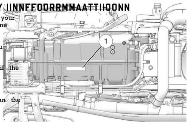
ENGINE IDENTIFICATION NUMBER
The engine number is stamped into the right crankcase beneath the balance shaft cover. The engine number is positioned behind the right floorboard with the engine installed in the frame. Record the number in the space provided on page 7.
SSAAFFEETTYY
AABBOOUUTT TTHHEE RRIIDDEERR''SS MMAANSIAVAPLEE RRIIDDIINNGG PPRRAACCTTIICCEESS
WARNING
Failure to follow all recommended precautions and procedure could result in serious injury or death. Always heed all precautions and follow all operation, inspection and maintenance procedures outlined in this manual.
All references to RIGHT, LEFT, FRONT or REAR are from operator's perspective when seated in a normal riding pos you have questions about the operation or maintenance of motorcycle after you've read this manual, please see your authorized dealer. To locate the nearest authorized INDIAN MOTORCYCLE dealer, visit the INDIAN MOTORCYCLE web www.indianmotorcycle.com.
Carefully read and understand the information found in the section beginning on this page. To keep your motorcycle condition on the road or in storage, understand and follow procedures outlined in the Maintenance section beginning on page .
Bring the manual along when you ride. Following the prec and procedures in the manual will add to your enjoyment keep you safe. If you lose or damage this manual, please a new one through any authorized INDIAN MOTORCYCLE of This rider's manual should be considered part of the motor and should remain with the motorcycle when ownership cha
WARNING
Iul proper use of a motorcycle can result in serious injury of safety you, your passenger and others. To minimize the risk of handicap and understand the information contained in this section before operating the motorcycle. This section contains safety information specific to the INDIAN MOTORCYCLE, as well as the information about general motorcycle safety. Anyone who rid it on the motorcycle (operators and passengers) must follow these safety precautions.
MOTORCYCLING HAS INHERENT RISKS
You can minimize those risks, but you can't eliminate them completely. Even if you're an experienced motorcycle operator passenger, read all of the safety information in this manual I peak the motorcycle.
Take a rider education course from the Motorcycle Safety Foundation ^SM or another qualified instructor. The course will help you develop or refresh your expertise in safe riding through instruction and riding. For information on Motorcycle Safety Foundation ^SM rider education courses in your area, purchase 1-800-446-9227 or visit www.msf-usa.org.
Read, understand, and follow all information in this manual. Observe all maintenance requirements specified in this man: See the INDIAN MOTORCYCLE Service Manual or an author INDIAN MOTORCYCLE dealer.
SAFETY
DDEESSIGGNN CCHHAARRAACCTTEERRIISSTTIICC69 SAllow only licensed, experienced operators to ride your motorcycle and then only after they have become familiar with other vehicles and operation. Make sure all riders read and
- The motorcycle is designed for on-road use with one rider one passenger if the motorcycle is equipped with a passenger seat and passenger foot rests). Never exceed the GVWR or the GAWR. Refer to the Specifications section, or the Manufacturi Information/VIN label on the motorcycle frame for model-specific information.
- Riding off-road, riding with more than one passenger, or carrying weight exceeding the maximum weight rating can make handling difficult, which could cause loss of control.
- During the first 500 miles (800 km) of operation, follow al break-in procedures as outlined on page 75. Failure to do result in serious engine damage.
-
If your motorcycle is equipped with saddlebags, a windshield a passenger backrest, be prepared to reduce operating spe to maintain stability.
understand this rider's manual before riding.
For not ride when you're fatigued, ill or under the influence of alcohol, prescription drugs, over-the-counter drugs or any other drugs. Fatigue, illness, alcohol and drugs can cause drowsiness loss of coordination and loss of balance. They can also affect your awareness and judgment.
If your motorcycle operates abnormally, correct the problem immediately. See the INDIAN MOTORCYCLE Service Manual or an authorized INDIAN MOTORCYCLE dealer.
Ride defensively, as if you are invisible to other motorists, can spread daylight. A motorist's failure to see or recognize a motorcycle is the leading cause of automobile/motorcycle
eleccidents. Ride where you're clearly visible to other motorists, and observe their behavior carefully. -
Be especially cautious at intersections, as these are the most likely places for an accident.
To prevent loss of control keep your hands on the handleb and your feet on the footrests.
Be aware that a highway bar is not designed to protect the trondo injury in a collision. - Obey the speed limit and adjust your speed and riding technique based on road, weather and traffic conditions. As travel faster, the influence of all other conditions increases, which can affect the motorcycle's stability and increase the possibility of losing control.
FFOOLLLOOWW TTHHEESSEE GGEENNEERRAALL PPRRAACCTTIICCEESS
- Before each ride, perform the Pre-Ride Inspections. Failure so may result in damage to the motorcycle or an accident
- Until you're thoroughly familiar with the motorcycle and all controls, practice riding where there is little or no traffic. Practice riding at a moderate speed on various road surfaces and in different weather conditions.
- Know your skills and limits, and ride within them.
SAFETY
- Do not move or operate the motorcycle with the steering. Bokendaximize braking effectiveness, use the front and rear brake (if equipped), as the severely restricted steering could result together. Be aware of the following braking facts and practi
loss of control. - The rear brake provides 40% of the motorcycle's stoppin
- Reduce speed when:
- The road has potholes or is otherwise rough or uneven.
- The road contains sand, dirt, gravel or other loose substances.
- The road is wet, icy or oily.
- The road contains painted surfaces, manhole covers, metal grating, railway crossings or other slippery surfaces.
- The weather is windy, rainy or otherwise causing slippery rapidly changing conditions.
- Traffic is heavy, congested, not allowing sufficient space between vehicles or otherwise not flowing smoothly.
- You are being passed in either direction by a large vehicle that may produce a wind blast in its wake.
- When approaching a curve, choose a speed and lean angle that emergency. Brake efficiency will gradually increase during allows you to pass through the curve in your own lane without this seating period.
applying the brakes. Excessive speed, improper lean angle braking in a curve can cause loss of control. - Ground clearance is reduced when the motorcycle leans. Do not allow components to contact the road surface when leaning the park the motorcycle clear of flammable materials and where people are not likely to contact hot components.
motorcycle in a curve, as this could cause loss of control. - Do not tow a trailer. Towing a trailer can make the motorcycle PRRRROOTTEECCTTIIVVEE AAPPPPAARREELL
hard to handle. - Retract the sidestand fully before riding. If the sidestand fully retracted, it could contact the road surface and cause of control.
| is not | IMPORTANT |
| e lowear protective apparel to decrease the risk of inju increase riding comfort. | |
SAFETY
- Always wear a helmet that meets or exceeds established saWear gloves, a jacket, heavy boots and long pants to preve standards. Approved helmets in the USA and Canada bear andise injury from abrasions, lacerations or burns should the Department of Transportation (DOT) label. Approved helmets motorcycle fall. Wear boots with low heels, as high heels ca Europe, Asia and Oceania bear the ECE 22.05 label. The EGEch on pedals or footrests. The combination of boots and I mark consists of a circle surrounding the letter E, followed should completely cover legs, ankles and feet, protecting skin the distinguishing number of the country which has granted from engine and exhaust system heat.
approval. The approval number and serial number will also be not wear loose, flowing clothing or long boot laces, as displayed on the label. Laws in some areas require that you can watch on handlebars, levers or footrests, or they can be an approved helmet. Head injuries are the leading cause of entangled in the wheels, causing loss of control and serious fatalities in accidents involving motorcycles. Statistics prove that injury.
an approved helmet is the most effective protection in preventing or reducing head injuries. The helmet should fit snugly, be securely fastened, have no obvious defects, and not previously been involved in an accident/crash. - Wear eye protection to protect eyes from wind or airborne particles and objects. Wearing a face shield can help pro your face in an accident/crash and protect face from wind airborne particles or objects. Laws in some areas require you wear eye protection. We recommend that you wear approved Personal Protective Equipment (PPE) bearing markings such as VESC 8, V-8, Z87.1, or CE. Make sure protective eyewear is kept clean.
- All riders should wear bright or light-colored and/or refle clothing to improve visibility to other motorists. A motorist's failure to see or recognize a motorcycle is the leading cause of automobile/motorcycle accidents.
Use the following guidelines when attaching cargo or accessories to, the motorcycle. Where applicable, these guidelines also refer active contents of any accessories.
t CGAARRRRYYIINNGG AA PPAASSSSEENNGGEERR

CCAARRRRYYIINNGG CCAARRGGOO
- Keep cargo and accessory weight to a minimum, and keep as close to the motorcycle as possible to minimize a change the motorcycle's center of gravity. Changing the center of gravity can cause loss of stability and handling and could cause of control.
- Adjust ride height as needed. See page 106.
- Do not exceed the gross vehicle weight rating (GVWR) for your motorcycle.
- SAADDDDLLEEBBAAGGSS,, TTRRUUNNKK AANN Whenever operating a motorcycle equipped with cargo storage
- Distribute weight evenly on both sides of the motorcycle. Features such as saddlebags, a trunk, racks, glove boxes or Maintain even weight distribution by checking accessories and age compartments: cargo to make sure they're securely attached to the motorcycle before riding and whenever you take a break from riding. Never ride at excessive speeds. Storage features and cargo Uneven weight distribution or sudden shifting of accessories combined with the lifting or buffeting effects of wind, can cargo while you're riding may cause difficult handling, loss of motorcycle unstable and cause loss of control. control and driving hazards for other motorists (if cargo falls) Distribute weight evenly on each side of the motorcycle. from the motorcycle).
- For riding comfort and to ensure proper ground clearance, trunk or other storage compartment. Refer to the storage adjust rear shock air pressure (if equipped) as specified on capacity label located on or near the storage feature. label located under the left side cover. See page 106. • NEVER EXCEED the GROSS VEHICLE WEIGHT RATING (GV)
- Do not attach large or heavy cargo such as sleeping bags or duffel GROSS AXLE WEIGHT RATING (GAWR), regardless of bags or tents to the handlebars, front fork area or front feeder. Whether or not any storage feature is loaded to capacity. Cargo or accessories placed in these areas can cause insta#eeding the weight rating can reduce stability and handli (due to improper weight distribution or aerodynamic changes) and cause loss of control. and could cause loss of control. Such items can also block air flow to the engine and cause overheating that can damage the engine.
- Do not exceed the maximum cargo weight limit of any accessory (see accessory instructions and labels). Do not attach cargo because INDIAN MOTORCYCLE cannot test and make specific an accessory not designed for that purpose. Either circum recommendations concerning every accessory or combination of could result in an accessory failure that could cause loss accessories sold, the operator is responsible for determining the control.
The motorcycle can be safely operated with any accessories
• Always obey posted speed limits. - Do not attach anything to the motorcycle unless specifically installed accessories: designed for that purpose by INDIAN MOTORCYCLE.
SAFETY
- Do not install accessories that impair operator visibility or stability, handling or operation of the motorcycle. Before installing an accessory, be sure that it does not:
- reduce ground clearance when the motorcycle is either leaned or in a vertical position;
- limit suspension or steering travel or your ability to o controls;
- displace you from your normal riding position;
-
obscure lights or reflectors.
-
Bulky, heavy or large accessories can cause instability (d the lifting or buffeting effects of wind) and loss of contr
- Do not install electrical accessories that exceed the capacity of the motorcycle's electrical system. Never install higher water light bulbs than those supplied as original equipment. An electrical failure could result and cause hazardous loss of power or lights, or damage to the electrical system.
- Use only genuine INDIAN MOTORCYCLE accessories design for your model.
- Do not exceed the gross vehicle weight rating (GVWR) motorcycle.
- Adjust ride height as needed.
MMOODDIFFIICCAATTII0ONNSS
Modifying the motorcycle by removing any equipment or by adding equipment not approved by the manufacturer may vov your warranty. Some modifications may not be legal in your operation. If in doubt, contact your authorized INDIAN MOTORCYCLE dealer.
the

CAUTION
Modifications could make the motorcycle unsafe to ride and could result in serious injury to operator or passenger, as we damage to the motorcycle.
PARKING THE MOTORCYCLE
When leaving the motorcycle unattended, turn the engine off. If you outo motorcycle is equipped with a keyed ignition, remove the ignition key to prevent unauthorized use.
| tage | NOTE | |||||||
| engine | Do not store your key fob near the motorcycle. | |||||||
Park the motorcycle where people are not likely to touch the engine or exhaust system or place combustible materials near these hot areas. Do not park near a flammable source such as Peresche heater or an open flame, where hot components could ignite combustible materials.
Park the motorcycle on a firm, level surface. Sloped or soft surfaces may not support the motorcycle. If you must park on slope or soft surface, follow the precautions outlined on page 8
ANTI-LOCK BRAKE SYSTEM RESPONSE
When the anti-lock brakes engage during a braking event, the rider will feel pulsing at the brake levers. Continue to apply ste pressure to the brakes for the best stopping performance.
FFUUEELL AANNDD EEXXHHAAUUSSTT SSAAF
Always heed these fuel safety warnings when refueling or servicing the fuel system.

WARNING
Gasoline is highly flammable and explosive under certain conditions.
• Always exercise extreme caution whenever handling gas
• Always turn off the engine before refueling.
• Always refuel outdoors or in a well-ventilated area.
- Open the fuel cap slowly. Do not overfill the tank. Do tank neck.
- Do not smoke or allow open flames or sparks in or n area where refueling is performed or where gasoline is
FEETTYY

WARNING
Gasoline and gasoline vapors are poisonous and can cause serious injury.
- Do not swallow gasoline, inhale gasoline vapors, or spill gasoline. If you swallow gasoline, inhale more than a few breaths of gasoline vapor, or get gasoline in your eyes, a physician immediately.
ne. If gasoline spills on your skin or clothing, immediately was off with soap and water and change clothing. - Exhaust gases contain carbon monoxide, a colorless, odorle gas that can cause loss of consciousness or death in a sl not fill the time.
- Never start the engine or let it run in an enclosed area.
- Never inhale exhaust gases.
- stored.
SAFETY
SSAAFFEETTYY MMAAIINNTTEENNAANNCCCEE
WARNING
Failure to perform safety maintenance as recommended can result in difficult handling and loss of control, which could in serious injury or death. Always perform the safety maintenance procedures as recommended in this manual. Perform maintenance and repairs promptly. See the INDIAM MOTORCYCLE Service Manual or an authorized INDIAN MOTORCYCLE dealer or other qualified dealer.
- Before each ride, perform the Pre-Ride Inspections.
- Perform all periodic maintenance at the recommended int outlined in the Periodic Maintenance section.
- Always maintain proper tire pressure, tread condition and tire balance. Inspect tires regularly and replace worst damaged tires promptly. Use only approved replacement See the Specifications section.
- Always ensure proper steering head bearing adjustment. Regularly inspect the rear shock absorber and the front fluid leaks or damage. Make any necessary repairs prom See page 110.
- Clean the motorcycle thoroughly to reveal items in need RCC: W99PI01, W99PI02 repair.
- Fasteners must meet original specifications for quality, finish and type to ensure safety. Use only genuine INDIAN This device complies with Part 15 of the FCC Rules and Cana MOTORCYCLE replacement parts, and ensure that all fastenersense-exempt RSS-210 standard. Operation is subject to the are tightened to the proper torque. following two conditions:
Do not engage the side stand during truck or trailer transportation.
tires This vehicle complies with UN ECE Regulation 10 requirements and Canadian ICES-002.
RCC: W99PI01, W99PI02
IC: 8296A-PI01; 8296A-PI02
This device complies with Part 15 of the FCC Rules and Cana license-exempt RSS-210 standard. Operation is subject to the following two conditions:
TTRRAANNSSPPOORRTTIINNGG TTHHEE MMOOTTO
If you must transport the motorcycle:
Use a truck or trailer. Do not tow the motorcycle with anot vehicle, as towing will impair the motorcycle's steering and result handling.
Position and restrain the motorcycle in an upright position. Do not restrain the motorcycle using the handlebars.
Loop tiedown straps (from the front) up and over the lower clamp, using care to not interfere with wiring and brake line Place tiedowns as wide apart as possible on the truck or tr bed for best stability.
wheel EELLEECCTTRROOMMAAGGNNEETTIICC IINNTTEEF
KEYFOB AND VEHICLE CONTROL MODULE FCC/IC COMPLIANCE STATEMENT
- THIS DEVICE MAY NOT CAUSE HARMFUL INTERFERENCE REPORTING SAFETY DEFECTS
- THIS DEVICE MUST ACCEPT ANY INTERFERENCE RECEIVED. If you believe that your vehicle has a defect that could resist crash or cause injury or death, you should immediately inform National Highway Traffic Safety Administration (NHTSA) in addition to notifying INDIAN MOTORCYCLE in writing.
GGRROOSSSS VVEEHHIICCLLEE WWEEIIGGHHTT RRAATTUNNGG (CGVWWWR)

WARNING
Exceeding the gross vehicle weight rating of your motor reduce stability and handling and could cause loss of NEVER exceed the GVWR of your motorcycle.
If RNASA receives similar companies, may open an investig
and if it finds that a safety defect exists in a group of veh may order a recall and remedy campaign. However, NHTSA
become involved in individual problems between you, your INDIAN MOTORCYCLE dealer or INDIAN MOTORCYCLE.
ontrol.
To contact NHTSA, or obtain other information about motor vs safety, you may either call the Vehicle Safety Hotline toll-free 1-888-327-4236 (TTY: 1-800-424-9153), visit the NHTSA website
The maximum load capacity of your motorcycle is the maximum weight you may add to your motorcycle without exceeding the safercar.gov, or write to:
GVWR. This capacity is determined by calculating the difference ADMINISTRATOR, NHTSA
between your motorcycle's GVWR and wet weight.
1200 New Jersey Avenue, SE
West Building
Washington, DC 20590
Refer to the Specifications section of this manual or the
Manufacturing Information/VIN label on the motorcycle frame for model-specific information.
When determining the weight you will be adding to your motorcycle, and to ensure you do not exceed the maximum load capacity, include the following:
- Operator body weight
- Passenger body weight
- Weight of all rider's apparel and items in or on apparel
- Weight of any post-production accessories and their contents
- Weight of any additional cargo on the motorcycle
SAFETY
SSAAFFEETTYY AANNDD IINNFFOORRMMAATTII0ONN LLAABBEELLSS
NOTE
Models shown for reference only. Safety label locations may vary depending on model.
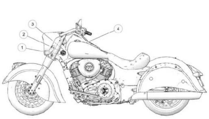
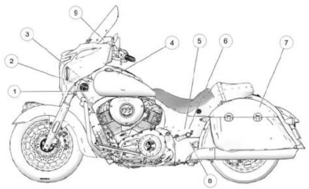
① Vehicle Identification Number (VIN) (side of steering head)
② Vehicle Emission Control Information (VECI)
③ Noise Emission Control Information (NECI)
④ Operator Warning/Fuel Recommendation
⑤ Shock Air Pressure Warning (under side cover)
⑥ Rear Wheel Service Warning (under side cover)
⑦ Saddlebag / Cargo Warning
⑧ Rear Tip-Over Bar Warning
⑨ Dashboard Cargo Capacity Warning
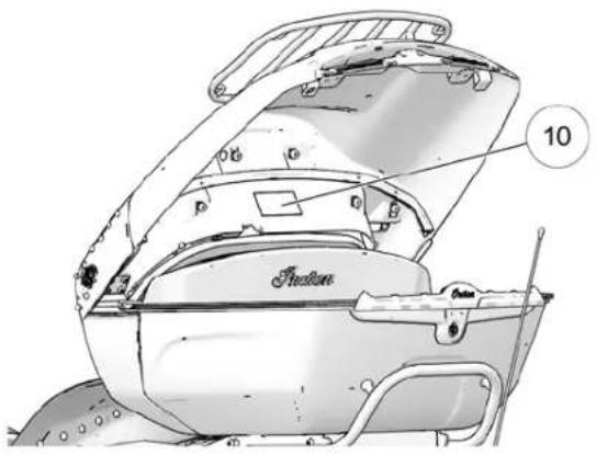
NOTE
Models shown for reference only. Safety label locations may vary depending on model.
natural_image
Technical line drawing of a mechanical component with labeled parts (no readable text or symbols)⑩ Trunk/Trunk Rack Capacity Label
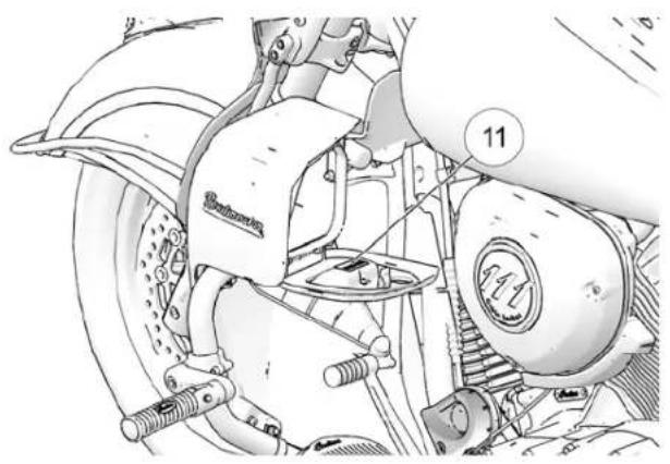
⑪ Lower Fairing Glove Box Cargo Capacity Label (inside covers)
IINNSSTTRRUUMMEENNTTSS,, FFEEAATTUURREESS AANNDD CCOONNTTRROOLLSS CCOONNSSOOLLEE
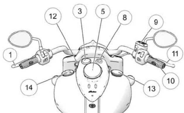
① Clutch Lever
② Phone Storage Compartment (if equipped)
③ Fuel Gauge (if equipped)
④ Speedometer/ Fuel Gauge (if equipped)
⑤ Instrument Cluster (if equipped)
⑥ Ride Command™ (if equipped)
⑦ Tachometer (if equipped)
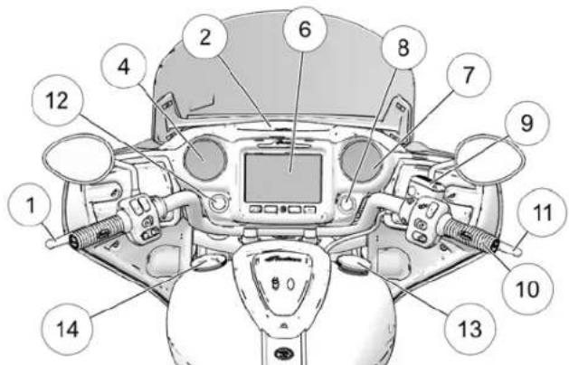
⑧ Power Switch/Security Light
⑨ Front Brake Master Cylinder
⑩ Throttle Grip
⑪ Front Brake Lever
⑫ Auxiliary Light Switch (if equipped)
⑬ Fuel Cap
⑭ Ornamental Cap (Do not remove)
SSWWIITTCCHH LLOOCCAATTIIIONNSS
LLEEFFTT CCOONNTTRROOLL
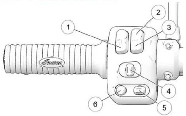
① Horn
② Hi Beam
③ Low Beam/ Flash to Pass
④ Turn Signal/Hazard Signal
⑤Screen List Select (if equipped)
⑥ Audio Control Switch (if equipped)
RRIIGGHHTT CCOONNTTRROOLL
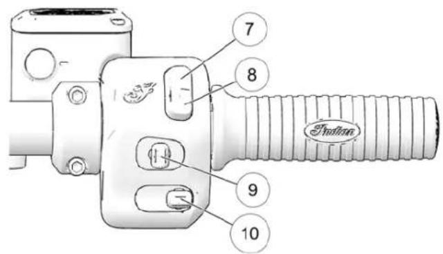
⑦ Engine Stop Switch
⑧ Engine Start/Run Switch
⑨ Cruise Control Switch
⑩ Windscreen Control Switch (if equipped)
TTOOGGGGLLEE SSWWIITTCCHHEESS
All models are equipped with toggle switches on the front side and right handlebar controls.
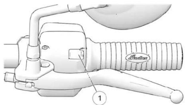
Left Control Right Control
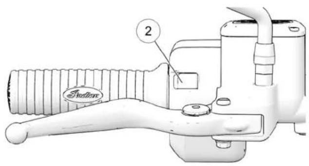
The power switch must be ON for the toggle switches to function. Use the right-hand switch to navigate through menus or accept dialog boxes on Ride Command display. Use the left-hand switch to back out of menus, decline dialog boxes, hang up phone calls, and toggle through display screens.
AADDDIITTIIOONNAALL SSWWIITTCCHHEESS
NOTE
Models shown for reference only. Switch locations may vary depending on model.
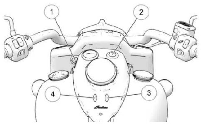
① Auxiliary Light Switch (if equipped)
② Power Switch
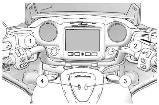
③ Power Locks (if equipped)
④ Heated Handgrips (if equipped)
SSWWIITTCCHH SSYYMMBBOOLSS
| SYMBOL | SWITCH DESCRIPTION | |
 | Horn Switch | Press the horn switch to sound the horn. |
 | High Headlight Beam Switch | The high headlight beam switch activates the high headlight beam. See page 29. |
 | Low Headlight Beam Switch | The low headlight beam switch activates the low headlight beam. Press down momentarily to activate Flash to Pass. See page 29. |
 | Turn Signal Switch | Move the switch to the left to activate the left turn signals. Move the switch to the right to activate the right turn signals. A signal will deactivate automatic when speed or distance reach predetermined levels. To cancel a signal manually, move the switch to the center position and push it inward.Momentary Feature: Move the turn signal switch left or right and hold it in the position for at least one second. The momentary feature will activate and the signal will then cancel when the switch is released. |
 | Emergency Flasher Switch (Hazard Switch) | The hazard switch activates and cancels the emergen flashers. See page 26. |
 | Screen List Select Switch | The Screen List Select Switch (if equipped) is navigate through rider screens. |
| SYMBOL | SWITCH | DESCRIPTION |
 | Audio Control Switch | The Audio Control Switch allows users to control audio system features from the left control block page 28. |
 | Stop Switch | Press the bottom of the switch (RUN) to allow engine to start and run. Press the top of the stop (STOP) to stop the engine. See page 26. |
 | Starter Switch | Use the starter switch to start the engine. The stop/run switch must be in the RUN position. See 26. |
 | Power Switch | On cruiser models the power switch is located the instrument cluster. On touring models the switch is located on the fairing, below the tackle Press and release the power switch to enable a disable all electrical power to the vehicle. See |
 | Left-Hand Trigger Switch | Use the left-hand switch to back out of menus, dialog boxes, hang up phone calls, and toggle display screens. See page 22. |
 | Right-Hand Trigger Switch | Use the right-hand switch to navigate through an accept dialog boxes on Ride Command display. |
INSTRUMENTS, FEATURES AND CONTROLS
SSWWIITTCCHHEESS PPOOWWEERR SSWWIITTCCHH
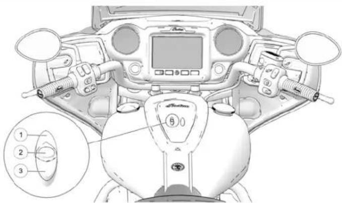
The power switch is located on the console for all non-fairing motorcycles. The power switch is located on the dash for all models equipped with the infotainment dash. Press and release the power switch to enable or disable all electrical power to the vehicle. The power switch does not have to be on to start the engine.
To disable all electrical power if the motorcycle is moving and the engine is running, press and hold the power switch for more than three (3) seconds.
NOTICE
To save battery power, the vehicle will automatically power off after five minutes of inactivity. Automatic power down can be overridden on bikes equipped with an INDIAN MOTORCYCLE Ride Command display through the settings menu
NOTICE
The headlights and any accessories plugged into power will remain on until the power switch is turned
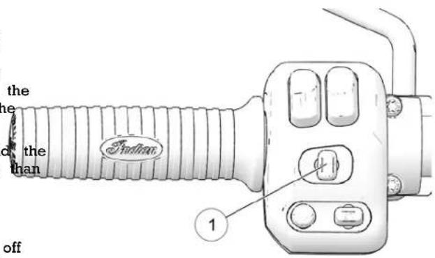
To activate the hazard switch, press on the center of the turn switch ①.
- Press and hold the switch to activate the flashers. - Press the switch again to cancel the flashers.
HHAAZZAARRDD SSWWIITTCCHH
The power switch must be ON to activate the flashers, but once activated, the flashers will continue to flash when the power switch is turned off. When the flashers are active, all four turn signals flash.
EENNGGIINNEE SSTTOOPP//RRUUNN SSWWIITTCCHH
Use the engine stop/run switch to turn the engine off quickly.
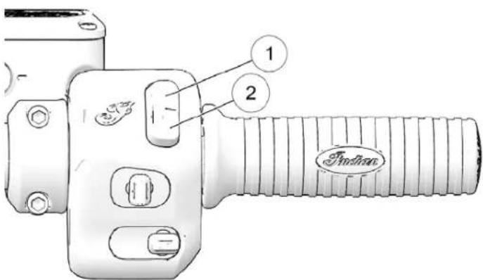
- Press the top of the switch (SEOB) interrupt the circuits and stop the engine. The engine should not start or run which switch is in the STOP position.
- Press the bottom of the switch②RUNcomplete the circuits and allow the engine to start and run.
- Press and Release the bottom switch②(RUN)art the engine.
KKEEYYLLEESSSS IIGGNNIITTIIOONN
SSTTAARRTTIINNGG KKEEYY FFOOBB OOPPEERRAATTII
When the electrical system is activated with either the power switch or the starter switch, the key fob must be within ran key fob is not detected, the security light and/or power swir flash. The electrical system will automatically shut down.
The starter motor will not engage during this time. If a key not available, your personal identification number (PIN) can be entered using the turn signal switches, or on the Ride Comm display screen (if equipped), to unlock the security system. S page 140.
DDRRIIVVIINNGG KKEEYY FFOOBB OOPPEERRAATTIIOON
After starting the engine, the Vehicle Control Module (VCM) verify that the key fob is within range again when shifting it neutral into gear. The security light may turn on during this. The VCM will not search for the key fob again after the vehicle moved. If the key fob is lost during riding, the PIN will be to restart the vehicle.
If the key fob is not detected when shifting into gear:
- The horn will sound and the security light and/or power: will flash.
• The engine will then turn off.
• The electrical system will then automatically shut down.
INSTRUMENTS, FEATURES AND CONTROLS
KKEEYY FFOOBB SSTTOORRAAGGEE::
The key fob should not be stored in the phone storage compartment, or near devices that can interfere with radio such as cell phones, power supplies, or magnets, during operation.
NOTICE
When using a Bluetooth® audio device, pushing down on the ways audio control switch will pause the audio. To resume, press d on the audio control switch again.
AAUUDDIIOO CCOONNTTRROOLL SSWWIITTCCHH ((IFFEERHHIPPPPEEDD))
The Audio Control Switchallows users to control the audio system features from the left control block.
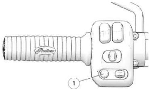
When the audio source is set to Tuner, press left or right to navigate through preset stations. Press and hold to seek.
PPEERRSSOONNAALL AAUUDDI100
When audio source is set to Bluetooth® Audio or USB/iPod®, left or right to navigate through audio tracks.
CCRRUUISSEE CCOONNTTRROOLL SSWWIITTCCHH
Cruise control can be activated and adjusted from the right co using the Cruise Control Switch
VVOOLLUUMMEE
To increase volume, press up on the audio control switch. To decrease the volume, press down on the audio control switch. To mute the volume, push in on the audio control switch.
INSTRUMENTS, FEATURES AND CONTROLS
| Toggle Position Function | |
| Left Set/Decelerate | |
| Center Off/On | |
| Right Resume/Accelerate | |
For more information about Cruise Control, see page 83.
HHIIGGHH//LLOOWW HHEEAADDLLIIGGHHTT BBEEAAMM SSHHTTCCHH
The headlights automatically come on when the engine is See page 47.
The high/low headlight beam switch toggles the headlight between high beam and low beam. To activate the high beas press the upper portion of the switch. To activate the low k press the lower portion of the switch. To momentarily flash headlights (Flash to Pass), press and hold the lower portion switch.
AUXILIARY LIGHT SWITCH (IF EQUIPPED)
The auxiliary lights provide additional lighting on each side of headlight. Some drivers prefer using the auxiliary lights when operating in foggy conditions or when passing a vehicle to improve visibility to other motorists.
Press the auxiliary light switch to turn the auxiliary lights on The switch background light changes color to indicate whether lights are on or off.
OFF: Red Light
ON: Green Light
The auxiliary lights turn off when the power switch is turned. The auxiliary lights automatically turn on when the engine state they were on when the engine was shut down.
The switch background light flashes if a fault exists with either
HAN D GRIP HEATER SWITCH (IF EQUIPPED)
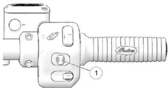
Press the top or bottom of the switch to turn the hand grip on. The center of the switch illuminates when heaters are or the center of the switch to turn the heaters off
INSTRUMENTS, FEATURES AND CONTROLS
The heaters have 10 heat levels, ranging from OFF (level 0) to highest heat (level 10). Press and release the top of the switch increase the heat level by one increment. Press and release the bottom of the switch decrease heat by one increment.
The heaters turn off when the engine is turned off. When the engine is restarted the heaters turn on at the previous heat level setting.
If the center of the switch flashes, the heaters may not be working properly. Please see your dealer.
SSAADDDDLLEEBBAAGG//TTRRUUNNKK LLOOCCKK S EEQQUUIIPPPPEEDD))
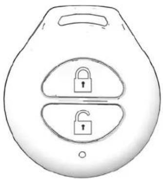
Use the key fob or the lock switch on the console to lock a unlock the electric saddlebag and trunk locks. When using the console lock switch, the key fob must be within range. If the fob is not detected, the security light and/or power switch will flash. The system will not perform the lock or unlock command
natural_image
Simple line drawing of a kettlebell with two lock symbols on its side (no text or labels)SSEEAATT HHEEAATTEERR SSWWIITTCCHHEESS ([IIF
The seat heater toggle switches are located on the lower left of the seat. The driver's switch the left switch, the passenger's switch ② (if equipped) is on the right.
INSTRUMENTS, FEATURES AND CONTROLS
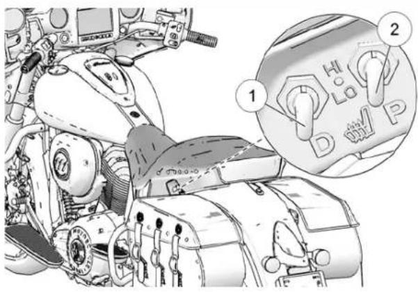
| Toggle Position Heat | Setting |
| Top HIGH | |
| Center OFF | |
| Down LOW |
IINNSSTTRRUUMMEENNTT CCLLUUSSTTEERR ((CORRUHSSEERR MMOODDEELLSS))
The instrument cluster includes the speedometer, indicator lamps and Multi-Function Display (MFD). ③ Multi-Function Display
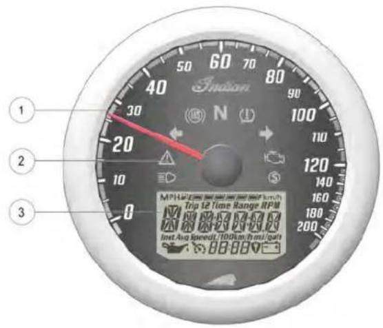
IINNSSTTRRUUMMEENNTT CCLLUUSSTTEERR ([BBAAGGGGEERRSS AANNDD TTOOUURRIINNGG I
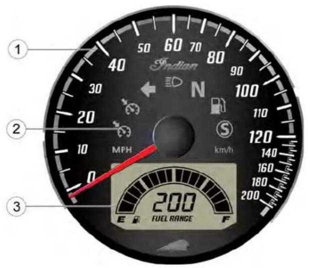
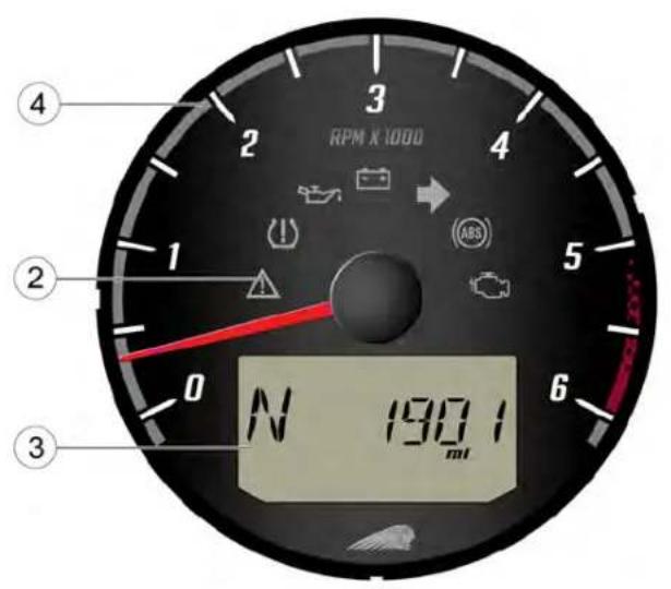
① Speedometer
② Indicator Lamps
③ Multi-function Display
④ Tachometer
IINNDDIICCAATTOORR LLAAMMPPSS
| LAMP INDICATES CONDITION | ||
 | Cruise Control Status Amber Lamp: | ruise control is enabled, but not set. When flashing, a cruise control related fault exists. Green Lamp: Cruise control is set the desired speed. Read the safety and operation procedures before using cruise control. |
 | Turn Signals One arrow flashes when the corresponding turn signal is activated. Both arrows flash when the hazard signal is activated. If there is a problem in the signal system, the lamps will flash at twice the normal rate. | |
| MPH | Vehicle Speed | When standard mode is selected, speed displays in miles per hour. |
| km/h | When metric mode is selected, speed displays in kilometers per ho | |
 | High Beam | The headlight switch is set to high beam. This indicator will flash there is a problem with the low or high beam light. |
| N | Neutral | The transmission is in neutral and the power switch is ON. |
INSTRUMENTS, FEATURES AND CONTROLS
| LAMP INDICATES CONDITION | ||
 | Low Fuel This lamp illuminates when approximately one gallon (3.8 liters) of fuel remains in the fuel tank. The LCD Display will switch into a Low Mileage Counter Mode to provide the rider with mileage tracking the time the indicator was activated. | |
 | Sidestand Light The sidestand light will turn on anytime the sidestand is down. | |
 | Chassis Fault The alert symbol illuminates if a chassis fault occurs. | |
 | Tire Pressure Monitoring System (TPMS) | The TPMS indicator illuminates if low tire pressure is detected. It also illuminate along with the Low Battery Voltage indicator when battery power is low, requiring service. |
 | Low Oil Pressure This lamp illuminates when oil pressure drops below a safe operating pressure while the engine is running. If this lamp illuminates while engine is running above idle speed, turn the engine off as soon safely possible and check the oil level. If the oil level is correct and lamp remains on after the engine is restarted, turn the engine off immediately. See your dealer. | |
INSTRUMENTS, FEATURES AND CONTROLS
| LAMP INDICATES CONDITION | ||
 | Low Battery Voltage This lamp illuminates when battery voltage is low. Turn non-essential accessories off to conserve power. Make sure the charging s operating properly. See page 146. This lamp also illuminates security light and/or power switch when the key fob battery with the TPMS lamp when the TPMS sensor battery is low. | |
INSTRUMENTS, FEATURES AND CONTROLS
| LAMP INDICATES CONDITION | ||
 | ABS Not Activated The indicator | remains on until the anti-lock system activates, which occurs when vehicle speed exceeds 6 MPH (10 km/h). When is illuminated, the anti-lock brakes will not activate, but the conventional brake system will continue to operate normally. |
 | Check Engine This lamp illuminates | briefly when the power switch is turned ON. This indicates proper function. If this lamp illuminates while the engine running, see an authorized dealer promptly. The light will remain the tilt sensor shuts down the engine. If abnormal sensor or operation is detected the light will remain on as long as the condition exists. Retrieve the error codes for diagnosis. |
 | Security The security indicator illuminates when the security system is activated. | |
SSPPEEEEEDDOOMMEETTEERR
The speedometer displays forward vehicle speed in either per hour or kilometers per hour.
TTAACCHHOOMMEETTEERR
The tachometer displays engine speed in revolutions per minute (RPM). A red line on the face of the gauge indicates the maximum safe engine speed.
Excessive engine speed can cause engine damage or failure, which could result in serious injury or death. Do not allow engine speed to exceed the red line.
FFUUEELL GGAAUUGGEE DDISSPPLLAAYY
The fuel gauge displays fuel level. For the most accurate sit on the motorcycle and bring it to the upright position.
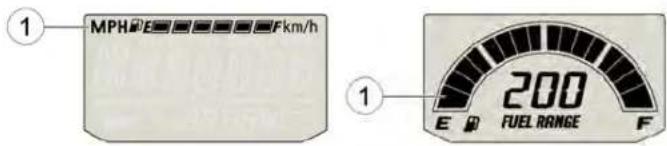
Non-fairing Models Fairing Models
The segments of the fuel gaugew the level of fuel in the fucllock tank. When the last segment clears, a low fuel warning is acgated Position All segments including the fuel icon will flash. Refuel promptly Engine Speed
MULTI-FUNCTION DISPLAY (MFD) MODES (IF EQUIPPED)
The power switch must be ON to access the MFD. Use the n switches ① to toggle through the modes of the multi-function display and to change settings in the display.
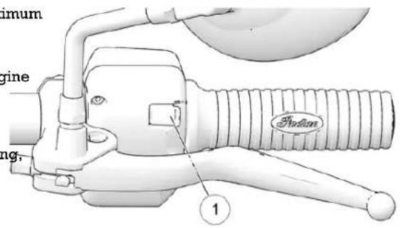
Available Modes:
- Odometer
- Trip Odometer 1
- Trip Odometer 2
fu€lock
cdotivatedPosition
Engine Speed
• Average Fuel Economy
- DC Voltage
• Ambient Air Temperature
- Fuel Range
- Tire Pressure Monitoring System (TPMS)
OODDOOMMEETTEERR
The odometer displays total distance traveled.
TTRRIIPP OODDOOMMEETTEERRSS
The trip odometers (Trip 1 and Trip 2) display total traveled since being reset. To reset a trip odometer, trip odometer, then press and hold the LEFT-TOGGLE the trip odometer resets to zero.
CCLLOOCCKK
TIP
The clock must be reset any time the battery has disconnected or discharged.
- Use the LEFT-TOGGLE switch to toggle to the odometer
- Press and hold the LEFT-TOGGLE switch until the hour flashes. Release the switch.
- With the segment flashing, tap the LEFT-TOGGLE switch advance to the desired setting.
- Press and hold the LEFT-TOGGLE switch until the next flashes. Release the switch.
- Repeat steps 3–4 twice to set the 10-minute and 1-minute segments. After completing the 1-minute segment, step 4 will save the new settings and exit the clock mode.
GGEEAARR PPOOSSIITTIIOONN
Gear position displays at all times while the engine is runnin unless a fault occurs with the gear position sensor.
EENNGGIINNEE SSPPEEEEEDD
toggleEnginchespeed displays in revolutions per minute (RPM). switch until
AAVVEERRAAGGEE FFUUEELL EECCOONNOOMMYY
Average Fuel Economy displays the vehicle's average fuel economy as of the last time the mode was reset. To reset, hold the left hand trigger while viewing the fuel economy d
been DDCC VVOOLLTTAAGGEE
The volt meter displays battery voltage. If the engine is not running, approximate battery voltage displays. If the engine is running, approximate charging voltage displays.
segment TTEEMMPPEERRAATTUURREE
The temperature area displays ambient air temperature. to
FFUUEELL RRAANNGGEE
The fuel range displays the distance the motorcycle can travel the remaining fuel in the fuel tank.
RREEAARR CCYYLLIINNDOEERR DDEEAACCTTIIVVAATTUOGNN Designed as an aid to reduce engine and exhaust heat to the ride. Rear models not equipped with Ride Command, do the following
Designed as an aid to reduce engine and exhaust heat to Rear Cylinder Deactivation turns off the rear cylinder when engine gets hot.
The following condition must be met for Rear Cylinder Deactivation to be enabled.
• Engine must be up to operating temperature
• Ambient Temperature must exceed 15 C
• Engine speed must remain below 1000 rpm
• Gear position must be 1, 2, or N
- Throttle must be in the closed position (0% throttle)
For models equipped with Ride Command, Rear Cylinder Deactivation can be turned off by accessing the settings me the drop-down from the top of the screen. Cylinder Deactiv controls are in the Vehicle Settings menu. When Rear Cylin Deactivation is functioning, an icon will illuminate at the top Ride Command display screen.
thePress the right-hand trigger until "CYLdeAC" displays.
- Hold down the right-hand trigger. "CD ON" or "CD OFF", display.
- Toggle to turn cylinder deactivation on or off. Press and hand right-hand trigger to save settings.
• CYLdeAC ON: rear cylinder can deactivate
• CYLdeAC OFF: rear cylinder cannot deactivate
RRIIDDEE MMOODDEESS
NOTICE
For models equipped with Ride Command, ride modes can be selected on the display. The following procedure is for mode not equipped with Ride Command.
To select a ride mode, do the following:
- Press right-hand trigger until Ride Md displays.
- Hold down on the right-hand trigger. STND, SPORT, or TOUR will display.
- Using the right-hand trigger, toggle to change ride mode.
- Press and hold right-hand trigger to save settings
INSTRUMENTS, FEATURES AND CONTROLS
NOTICE
Flashing ride mode means ride mode has been requested, but parameters to change the ride mode have not been met (throttle not in range, etc.)
HHEEAATTEEDD GGRRIIPPSS HHEEAATT LLEEVVEELL SSEETTTIINNGG ((IFF EEQQUUIIPPPPPEED))
The heated grips heat level displays momentarily after changing the heat level. For models equipped with Ride Command, a brief pop-up will appear on the touchscreen display when heat level is changed.
BBAATTTTEERRYY TTEENNDDEERR//HHEEAATTEEDD GGEEAARR PPLLUUGG
The Battery Tender/Heated Gear plug is located under the side panel.
left
DDIISSPPLLAAYY UUNNIITTSS ((SSTAANNDDAAI
The display can be changed to display either standard or m units of measurement.
| STANDARD DISPLAY | METRIC DISPLAY | ||
| Distance | Miles | Kilometers | |
| Fuel | U.S. Gallons | I = Imperial Gallons | Liter = Liters |
| Temperature | Fahrenheit | Celsius | |
| Time | 12-Hour Clock | 24-Hour Clock | |
INSTRUMENTS, FEATURES AND CONTROLS
- Stop the engine.
- Wait 10 seconds.
- Press and hold the LEFT-TOGGLE switch while pressing power switch.
- When the display flashes the distance setting, tap the LEFT-TOGGLE switch to advance to the desired setting.
- Press and hold the LEFT-TOGGLE switch to save the sett advance to the next display option.
- Repeat the procedure to change remaining display setting
MMIISSFFIIRREE DDEETTEECCTT100NN
If a misfire is detected, the check engine indicator lamp wddcegdis to flash and fuel will be cut to the affected cylinder(s). The powercheck engine indicator lamp will continue to flash until the ignition reason.
has been moved to the off position. Restarting the engine will clear the flashing indicator and restore fuel to both cylinders. If another misfire occurs, the check engine indicator lamp will resume flashing and fuel will once again be cut to the affected cylinder(s). After the rd misfire, P0314 misfire fault is determined & set, the check engine light will remain on and fuel will be cut to the affected cylinder(s). If this occurs, your INDIAN MOTORCYCLE dealer can assist.
| MESSAGE LOCATION | INDICATES | |
| ERROR | All | Checksum error (gauge malfunction) |
| LO(CHIEF/SPRING-FIELD) | DC Voltage Screen | Voltage remains below 11.0 for more than 10 seconds |
| OV(CHIEF/SPRING-TRELEND) | DC Voltage Screen | Voltage remains above 15.0 for more than 10 seconds |
volts
volts
EENNGGIINNEE EERRRROORR CCOODDEESS
The error screen displays only when the CHECK ENGINE light on or when it goes on and off during one ignition cycle. Err width is a sign display only during the current ignition cycle. When the power check switch is turned OFF, the code and message is lost, but before which if the fault reoccurs after restarting the engine.
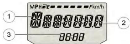
① Error Code Number (0-9)
DDIIAAGGNNOOSSTTIICC FFUUNNCCTTIIOONNAALLSuspect Parameter Number (SPN)
Certain conditions will cause an error message to display in③ Failure Mode Indicator (FMI) screen. If this occurs, please see your authorized dealer.
If the CHECK ENGINE indicator lamp illuminates, retrieve the error codes from the display. Error codes can also be viewed on Ride Command display (if equipped). Codes will include a short description of the error and recommend action.
- If the error codes are not displayed, use the LEFT-TOGGLE switch to toggle until "Ck ENG" displays on the main line of the display.
- Press and hold the LEFT-TOGGLE switch to enter the diagnostics code menu.
- Record the three numbers displayed in the gear position, clock and odometer displays.
- See an authorized dealer for code details and diagnosis.
LLOOWW 00111 PPRREESSSUURREE DDIISSPPLLAAYY
"LO OIL" displays under the following conditions.
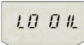
| CONDITION INDICATES ACTION REQUIRED | ||
| Engine oil pressure has dropped while the engine is running. | Oil pressure is below a safe operating pressure. | Stop the engine as soon safely possible and check the oil level. If the oil sufficient, but “LO OIL” continues to display after restarting the engine, stop the engine immediately. |
RRIIDDEE CCOOMMMMAANNDD™™ ((IIFF EEQQUUIIPPPPEEDD))
OOVVEERRVVIIEEWW
WARNING
Driving while distracted can result in loss of vehicle control, crash, and injury. We strongly recommend that you use extreme caution when using any device that may take your focus off the road. Your primary responsibility is the safe operating of your vehicle. We recommend against the use of any hand-held device while driving and encourage the use of voice-operated systems when possible. Make sure you are aware of all applicable local laws that may affect the use of electronic devices while driving.
For the most up-to-date information about your Ride Command display, visit ridecommand.indianmotorcycle.com
The RIDE COMMAND™ Display has 5 buttons:
- Rider Screen Button
- Navigation Button
- Control Button
- Bluetooth Button
- Audio Button
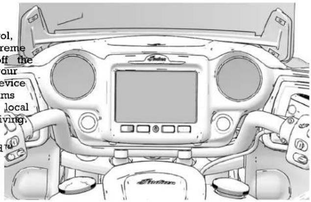
natural_image
Top-down technical sketch of a vehicle's front dashboard and steering wheel (no text or symbols visible)RRIIDDEE CCOOMMMMAANNDD™ BBUUTTTTOONNSS
| BUTTON FUNCTION | ||
 | Rider Screen Button Press | the Rider Screen button to access the customizable split screen menu system, access to ride data, vehicle status, and vehicle information. |
 | Audio Button Press the Audio Button to change the audio source, adjust volume level, and set radio presets. | |
 | Display On/Off Button Press the Display On/Off button to turn the Ride CommandTM display on while motorcycle is in use. | |
 | Bluetooth Button Press the Bluetooth button to pair a phone or headset to the Ride CommandTM display. | |
 | Navigation Button | Press the Navigation button to access Ride CommandTM navigation features equipped), find directions, and look up addresses, gas stations, and other p of interest. |
RRIIDDEE CCOOMMMMAANNDD SSEETTTIINNGGSS GENERAL INFORMATION
From the Settings Menu you can view important details about your vehicle and personalize your touchscreen display. The settings menu is comprised of four categories: Information, General, Time, and Vehicle. • Mileage
• Installed Software Version
- Oil Change Interval
GGEENNEERRAALL SSEETTTIINNGGSS
From the General settings menu you can do the following:
- Themes (Day/Night/Auto)
- Manage Bluetooth® Devices
- Change the Language
- Set the Speed Units of Measure (MPH or KPH)
- Set the Temperature Units (F or C)
- Update Software
CCLLOOCCKK
From the Time Settings you can do the following:
- Set the Time Format (12 hour or 24 hour)
- Enable GPS Time (automatically sets the time to the time you are currently in)
- Set Time (if GPS Time is not enabled)
VVEEHHIICCLLEE IINNFFOORRMMAATTIIOONN
From the Vehicle Settings you can do the following:
• Oil Life/ Service Reset
- Access Vehicle Diagnostics
DDOOWWNNLLOOAADD NNEEWW SSOOFFTTWWAARRE
For the latest software and maps for Ride Command, go to https://ridecommand.indianmotorcycle.com.
NOTICE
The display will automatically restart after a software update.
NOTICE
For map updates, a 32GB or greater USB drive formatted to is required.
HEADLIGHTS
The headlights automatically come on when the engine is sta
zone
WARNING
Motorcycle riders must remain as visible as possible at all To aid in this, the headlight must be on at all times. Do the ignition/headlight wiring to circumvent the automatic headlight feature.
The headlights operate only when the engine is running. You use the high/low headlight beam switch to override this function and allow the headlights to operate when the engine is not running. Turn the power switch on, then toggle the high/low headlight beam switch to turn the headlights on.
TTHHRROOTTTTLLEE CCOONNTTRROOLL GGRRIIPI
The throttle control grip is located on the right handlebar. Use throttle control grip to control engine speed.
While seated in the proper riding position:
- Roll the grip rearwartb open the throttle (increase engine speed and power).
- Roll the grip forwardb close the throttle (decrease engine speed and power), and cancel cruise control.
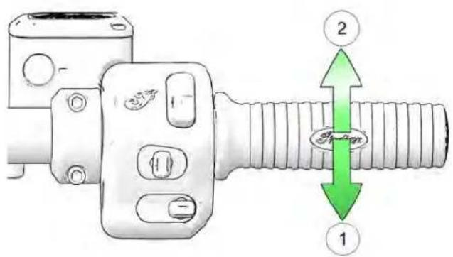
The control grip is spring loaded. When you release the grip, throttle returns to the idle position.
CCLLUUTTCCHH LLEEVVEERR
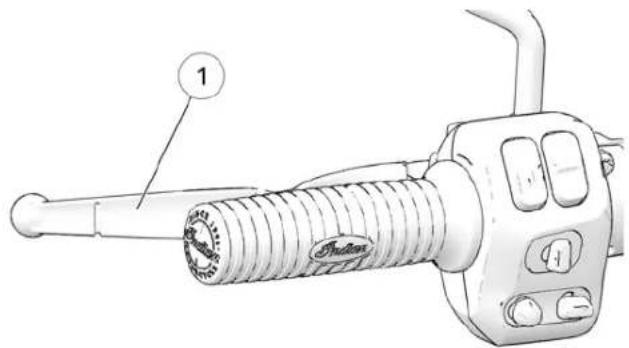
The clutch lever is located on the left handlebar. Disengage the clutch before shifting gears. For smooth clutch operation, pull lever quickly and release it in a brisk but controlled manner.
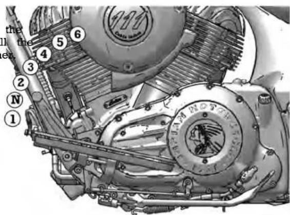
- Press downward on the toe lever to shift to a lower gear
- Lift upward on the toe lever to shift to a higher gear.
- Release the lever after each gear shift.
• See page 80, for gear shifting procedures.
• To disengage the clutch, pull the lever toward the handlebar.
• To engage the clutch, release the lever in a brisk but controlled manner.
GGEEAARR SSHHIIFFTT LLEEVVEERR
The gear shift lever is located on the left side of the motorcycle. Operate the lever with your foot.
TTIIRREE PPRREESSSSUURREE MMOONNIITTOQRRNUNGIGSY(MASTEEQMMUIIPPPPEEDD))
((TTPPMMSS)) ((IIFF EEQQUUIIPPPPEEDD))
NOTICE
On models equipped with a TPMS, the sensors are lo from the valve stem. Use caution when servicing tires, damaging a sensor, break the bead at the valve stem and 270^ from the valve stem as required.
Do not exceed the cargo capacity of a trunk, a cargo rack of trunk/cargo rack combination. The capacity for the trunk alone, well as for any trunk/cargo rack combination, is listed in the below. The capacity for a rack alone is 5 lbs. (2.2 kg). If you are rated 180°, the rack with 5 lbs. (2.2 kg) of cargo, do not add more than 25 to 11.3 kg to a hard trunk, or 20 lbs (9 kg) to a leather trur then at 90°
With a TPMS, the pressure of each tire can be viewed in and in the display for Infotainment motorcycles on rider scr dashes display instead of a pressure value while traveling a 15 MPH (24 km/h), the system may not be functioning pro. See your dealer for service.
| Hard Trunk 30 lbs (13.6 kg) | |
| the MFD Trunk 25 lbs (11.3 kg) | |
| beers If | |
| bCargo Rack (Alone) | 5 lbs (2.2 kg) |
The TPMS warning indicator will illuminate if low tire pressure is detected. Always correct low tire pressure promptly. Always inspect tire pressure and condition before each ride. See page 68.
The TPMS display may indicate an increase in tire pressure while riding, a normal occurrence as tires warm up. Riding into colder conditions may result in a drop in tire pressure as tires cool down. Regardless of conditions, low tire pressures should always be corrected promptly.
HHAARRDD TTRRUUNNKK RREEMMOOVVAALL ((IIFF EEQQUUIIPPPEEDD))
- If applicable, remove the left and right saddlebags and remove the trunk lock faster from each trunk latch.
natural_image
Technical diagram of a car interior showing a numbered component (1) and a handle, with no readable text or symbols.- Disconnect the trunk harness multi-plug
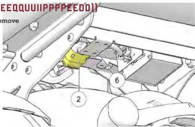
NOTE
The trunk harness multi-plug is located above the metal mounting plate ^⑥ .
INSTRUMENTS, FEATURES AND CONTROLS
- Lift the trunk latched to unlock the trunk from the mount.
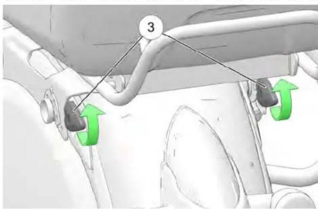
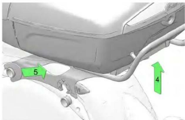
- Lift up on the rear of the and dunkide rearward to release the trunk from the motorcycle.
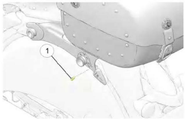
SSOOFFTT TTRRUUNNKK RREEMMOOVVAALL
- If applicable, remove the left and right saddlebags and the trunk lock faster from each trunk latch.
natural_image
Technical illustration of a mechanical assembly with numbered component (no text or symbols)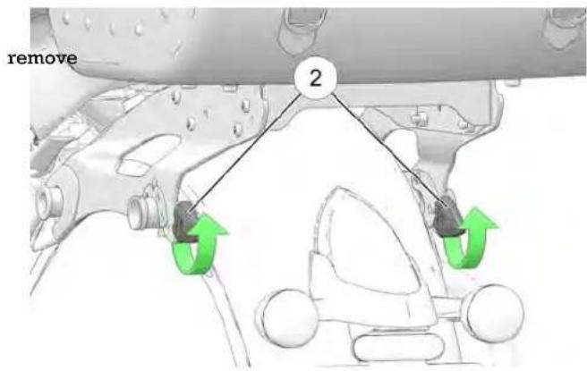
-
Lift up on the rear of the andnklide rearward to release the trunk from the motorcycle.
-
Lift the trunk latches to unlock the trunk from the mount.
INSTRUMENTS, FEATURES AND CONTROLS
SSAADDDDLLEEBBAAGGSS ((IIFF EEQQUUIIPPPPEEDD))
Do not exceed the weight limit of each saddlebag. Always distribute weight evenly in each of the saddlebags. Refer to the saddlebag/cargo warning label on or near the saddlebag for cargo capacity.
Hard bag capacity is 22 lbs. (10 kg) of cargo per side. Soft bag capacity is 15 lbs. (6.8 kg) of cargo per side.
HHAARRDD BBAAGG RREEMMOOVVAALL
- Remove the side cover.
- Unlock the electric saddlebag locks (if equipped).
NOTICE
The provided key can also be used in the latch release but to unlock the saddlebag lids.
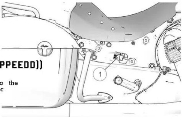
- Disconnect the saddlebag lock wrinear the seat.
- Press the lid latch release button and lift the lid.
INSTRUMENTS, FEATURES AND CONTROLS
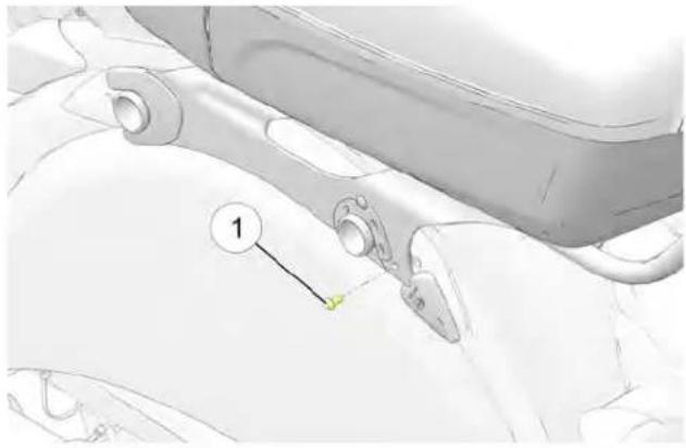
- Remove the saddlebag fastener ① bolts
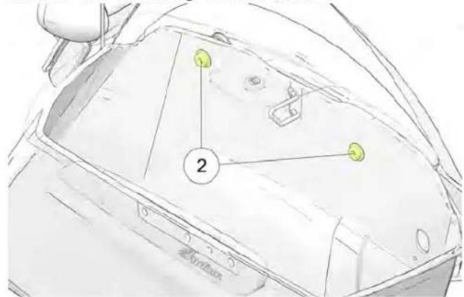
- Tilt the saddlebag away from the frame of the vehicle it.
- To reinstall, place the hard bag in a fully seated position muffler.
- Insert saddlebag fastener bolts and torque to specification
TORQUE
18 ft-lbs (24 Nm)
- Reconnect the electrical wiring.
- Reinstall the side cover, using care to avoid damaging electrical wires.
WARNING
Improper saddlebag installation can result in loss of control accident and driving hazards for other motorists (if saddlebag falls from the motorcycle). Always make sure saddlebag at mounted properly.
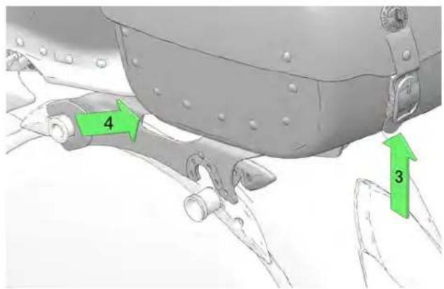
SSOOFFTT BBAAGG RREEMMOOVVAALL
- Unbuckle the saddlebag lid clasps and open the lid.
- Remove the saddlebag fastener bolts.
- Lift the saddlebag straight up, and then straight out to re
to remove
WARNING
Improper saddlebag installation can result in loss of control on the accident and driving hazards for other motorists (if saddleb falls from the motorcycle). Always make sure saddlebag at mounted properly.
INSTRUMENTS, FEATURES AND CONTROLS
- To reinstall, place the soft bag in position.
- Install the saddlebag fastener bolts and torque to specific
TORQUE
18 ft-lbs (24 Nm)
CAUTION
If the motorcycle weight is not resting on the sidestand, it will lock. In this situation, any movement of the motorcycle could cause the sidestand to retract slightly. If the sidestand is not full forward position when the motorcycle weight is rested on the motorcycle could fall over, possibly causing injury and damage to the motorcycle.
SSIIDDEESSTTAANNDD
The sidestand is equipped with a safety switch that prevents operation of the motorcycle if the sidestand is deployed.
To retract the sidestand, straddle the motorcycle and bring it fully upright position. Swing the end of the sidestand upward toward the motorcycle until it is fully retracted.
WARNING
An improperly retracted sidestand could contact the ground and cause a loss of control resulting in serious injury or death. Always retract the sidestand fully before operating the motorcycle.
To park the motorcycle, swing the end of the sidestand downward and away from the motorcycle until it is fully extended. Always turn the handlebars to the left for maximum stability. Lean the motorcycle to the left until the sidestand firmly supports the motorcycle.
WWIINNDDSSHHIIEELLDD ((IIFF EEQQUUIPPPPP WENDS)HIELD ADJUSTMENT (IF EQUIPPED))
WWIINNDDSSHHIIEELLDD RREEMMOOVVAALL
Use the windshield switch to adjust windshield height for the best wind deflection.
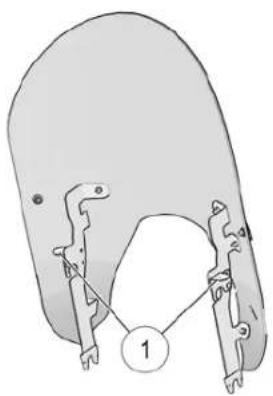
- If equipped with a quick-latch windshield, rotate the two latches ① upward.
natural_image
Diagram of a mechanical component with two clamped parts and a numbered label (1) pointing to a central feature (no text or symbols present)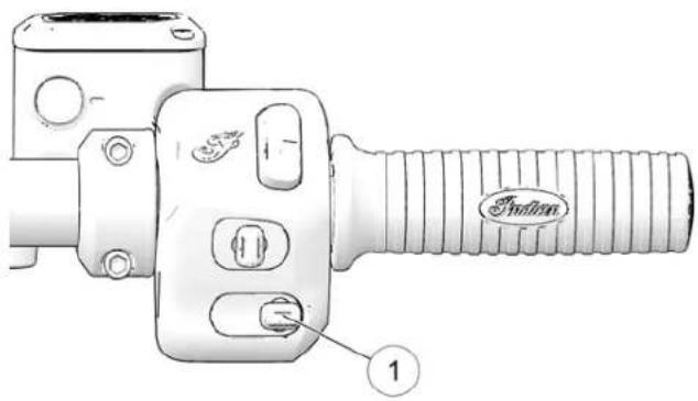
- Press up on the switch to adjust the windshield upward. - Press down on the switch to adjust the windshield downwa
-
From the front of the motorcycle, pull firmly on the upper windshield to remove the windshield from the upper mounts then pull the windshield upward and away from motorcycle. Double tap up or down on the switch to auto-adjust the windshield all the way up or down. If the windshield is t and the opposite direction is briefly pressed, the auto traw
-
Reverse this procedure to reinstall the windshield. Rotate the canceled, latches fully downward to secure the windshield.
WWIINNDDSSHHIIEELLDD CCAARREE ((IIFF EEQQUANIPPEEKB)MAKE SYSTEM (ABS)
Clean the windshield with a soft cloth and plenty of warm. The anti-lock brake system automatically adjusts brake pressure Dry with a soft clean cloth. Remove minor scratches with aneeded to provide optimum braking control, reducing the chance high-quality polishing compound designed for use on of wheel lock-up during hard braking events or when braking polycarbonate surfaces. rough, uneven, slippery or loose surfaces. See page 14.
NOTICE
Brake fluid and alcohol will permanently damage the wi Do not use glass cleaners, water or soil repellents, and or alcohol based cleaners on the windshield, as these can damage the windshield.
MMIIRRRROORRSS
Your vehicle is equipped with convex mirrors. Objects seen in mirror may be closer than they appear. Always adjust mirrors before riding.
To adjust the mirrors, sit on the motorcycle in the anticipated riding position. Adjust the mirrors so that you can see a small portion of your shoulders in each mirror.
- The anti-lock brake system cannot be turned off. Shield: The ABS indicator always illuminates when vehicle power is turned on. It remains illuminated until the anti-lock system produces (activates, which occurs when vehicle speed exceeds 6 MPH km/h).
-
When the lamp is illuminated, the anti-lock brakes will not activate, but the conventional brake system will continue to operate normally.
-
When the anti-lock brakes engage during a braking event, the rider will feel pulsing at the brake levers. Continue to apply steady pressure to the brakes for the best stopping performance.
If the ABS light does not come on when the key is turned ON or PARK position, your authorized INDIAN MOTORCYLE dealer can assist.
BBRRAAKKEESS
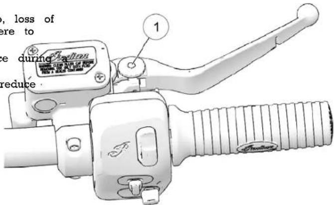
The front brake lever activates the front brake calipers. The rear brake pedal activates the rear brake caliper. For maximum brake effectiveness, apply the front brake lever and the rear brake pedal together.
- If the lamp continues to illuminate after vehicle speed exceeds 6 MPH (10 km/h), the ABS system is not functioning. See your INDIAN MOTORCYCLE dealer or other dealer promptly for control only the front brakes. The front brakes should be a service. simultaneously with the rear brakes. To apply the front brake
- Operating with non-recommended tires or improper tire the lever toward the handlebar. See page 82 for braking pressure may reduce the effectiveness of the anti-lock brake procedures. Front brake lever reach (distance to the hand gr system. Always use the recommended size and type of tire justable. specified for your vehicle. Always maintain the recommended tire pressure.
- The anti-lock brake system will not prevent wheel lockup, loss of traction or loss of control under all conditions. Always adhere to all safe motorcycle-riding practices as recommended.
- It is not unusual to leave tire marks on the road surface hard braking event.
- The anti-lock brake system does not compensate for or reduce the risks associated with:
- excessive speed
- reduced traction on rough, uneven or loose surfaces
- poor judgment
- improper operation
INSTRUMENTS, FEATURES AND CONTROLS
- Gently push and hold the lever away from the hand grip. adjuster wheel ^① is located on top of the lever.
- To increase reach distance, rotate the adjuster to a lower number.
- To decrease the reach distance, rotate the adjuster to a higher number.
RREEAARR BBRRAAKKEE PPEEDDAALL
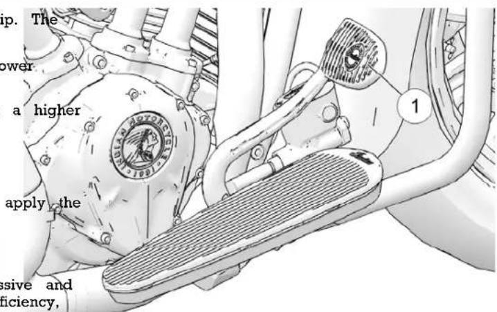
The rear brake pedals located on the right side of the motorcycle. Press downward on the rear brake pedal to rear brake.
WARNING
Resting your foot on the brake pedal will cause excessive and premature wear of brake pads and reduced braking efficiency, which could result in serious injury or death.
See page 82 for braking procedures.
PPAASSSSEENNGGEERR FFLLOOOORRBBOOAARR EEQQUUIIPPPPEEDD))
The passenger floorboard height and angle can be adjusted.
To adjust the angle, loosen both attachment①scRevate the floorboard to the desired position using the indicator mark on rear-facing support as a guide, then tighten the screws.
TORQUE
18 ft-lbs (24.4 Nm)
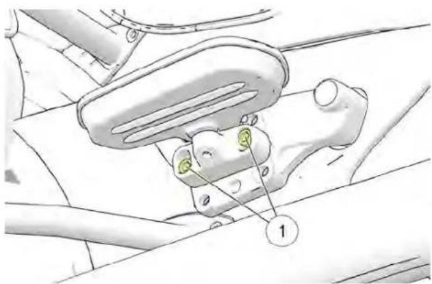
To adjust the height, remove both attachment screws. Move floorboard assembly to the next hole position, then reinstall fasteners, adjust the angle and tighten the fasteners.
TORQUE
18 ft-lbs (24.4 Nm)
FFUUEELL CCAAPP
The fuel filler caps located on the right side of the console. ornamental cap ^② is located on the left side of the console. D attempt to remove the ornamental cap.
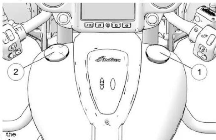
the the
- Turn the fuel cap counter-clockwise to remove it.
- See page for fueling instructions.
- To tighten the cap, turn it clockwise until the seal compr onto the tank, then continue to tighten until the cap ratch several times.
PPRREE--RRIIDDEE IINNSSPPEECCTTII0ONNSS
BBEEFFOORREE YYOOUU RRIIDDEE
To keep your motorcycle in safe operating condition, alway perform the recommended pre-ride inspections before each This is especially important before making a long trip and removing the motorcycle from storage.

WARNING
Failure to perform the recommended pre-ride inspections result in component failure while riding, which could be serious injury or death. Always perform the pre-ride ride before each ride. When inspection reveals the need adjustment, replacement or repair, perform the service p or your authorized INDIAN MOTORCYCLE can assist

WARNING
Read the entire Instruments, Features and Controls secti manual before riding your motorcycle. A complete understanding of the features and capabilities of your m is essential to its safe operation. Anything less may serious injury or death.
You must be familiar with all instruments and controls to pen the pre-ride inspections.
| when | TIP |
| During the pre-ride inspections you may use products potentially hazardous, such as oil or brake fluid. When of these products, always follow the instructions and with the product packaging. | |
could
result in When inspections reveal the need for adjustment, replacement for repair:
promptly refer to the maintenance section of this manual (page )
• refer to the INDIAN MOTORCYCLE Service Manual
• or see your authorized INDIAN MOTORCYCLE dealer or other dealer
ELECTRICAL INSPECTIONS
Turn the power switch on and move the stop/run switch to RUN before performing the following electrical inspections. Turn the power switch off after completing these inspections. If inspection of any electrical item reveals component failure, repair or replace the component before operating the motorcycle.
PRE-RIDE INSPECTIONS
| ITEM INSPECTION PROCEDURE | |
| Headlamp Move the headlight switch from low beam to high beam to turn the lights on and verify operation of both beams. Start the engine. Switch to high beam. Verify that the high beam indicator comes on and brightness increases. Press and hold the low beam switch to verify “Flash to Pass” functionality. | |
| Taillights/Brakelight | Verify that the taillights and license plate light illuminate. Verify that the taillight lamps increase in brightness when the front brake lever is applied and also when the rear brake pedal is applied |
| Turn Signals Move the turn signal switch to the left. Verify that front and rear left turn signals flash, as well as corresponding light on the indicator panel. Move the switch to the center position and push it in cancel the signal. Verify that the signals and the indicator light stop flashing. Repeat the right turn signals. | |
| Emergency Flashers | Press and hold the turn signal switch in for 1 second to activate flashers. Verify that all four turn flash, as well as the lamps on the indicator panel. Turn the flashers off. Verify that all signals lamps stop flashing. |
| Horn Press the horn switch. Verify that the horn sounds loudly. | |
| Neutral Indicator | Place the transmission in neutral. Verify that the neutral indicator lamp illuminates and that the letter "N" displays in the gear position display. |
| Low Oil Pressure Display | Start the engine. CHIEF MODELS/SPRINGFIELD: Verify that "LO OIL" is not displayed in the MFD. CHIEFTAIN MODELS/ ROADMASTER: Verify that the low oil pressure indicator is not illuminated. |
| Engine Stop/Run Switch Start the engine. Move the stop/run switch to the STOP position. Verify that the engine stops. | |
GGEENNEERRAALL IINNSSPPEECCTTII0ONNSS
| ITEM INSPECTION PROCEDURE | |
| Engine Oil Check | the oil level. See page 66. |
| Fuel Check the fuel level. See page 39. | |
| Fluid Leaks Check | the vehicle and the ground/floor for any fuel, oil or hydraulic fluid leaks. |
| Tires Inspect condition, pressure and tread depth. See page 68. | |
| Brake Operation Inspect pedal and lever movement. | |
| Brake Fluid Levels | Check front and rear brake fluid levels. |
| Brake Components | Inspect hoses and connections. |
| Throttle | Inspect hand grip and throttle movement. |
| Clutch | Check lever operation and freeplay. |
| Front Suspension | Check for leaks, debris and damage. |
| Steering | Check for smooth operation by turning handlebars full left and full right. |
| Rear Suspension | Inspect for leaks. CHIEFTAIN/ROADMASTER/SPRINGFIELD: Check shock movement and air pressure.. |
| Ride Height | Make sure preload is adjusted properly for load. |
| Rear Drive Belt | Check for wear or damage. Check drive belt tension. See page 98. |
| Sidestand | Verify smooth operation, inspect pivot bolt and spring. |
| Fasteners | Inspect for loose, damaged or missing fasteners. |
| Mirrors | Adjust for proper rear view. |
| Trunk/Saddlebags | If equipped, make sure the trunk and saddlebags are properly installed and that lids are securely closed. |
PRE-RIDE INSPECTIONS
EENNGGIINNEE OOIII LLEEVVEELL
With the semi-dry sump lubrication system, the engine oil level the dipstick will fluctuate, depending on the motorcycle's position and engine temperature when checked. To ensure a proper reading of the engine oil level, follow all inspection procedures closely.
WARNING
Operating with insufficient, deteriorated or contaminated engine oil will cause accelerated wear and may result in engine transmission seizure, which could result in loss of control and serious injury or death. Check the oil level frequently. We recommended checking the oil each time you refuel.
The engine must be at normal operating temperature when checking the oil level.
NOTICE
Oil level will NOT be accurate if checked on a cold NOT ADD oil to bring level to the FULL mark on a this can result in overfilling.
The oil fill cap/dipstick is located on the left side of the ①. A special tool is provided in the tool kit to assist w removal. Always use the recommended oil. See page 162.
CCHHEECCKKIINNGG TTHHEE EENNGGIINNEE OOIIILL I
- Start the engine and allow it to run until it reaches normal engine operating temperature.
cold engine, as 2. Stop the engine and wait 1-2 minutes before checking the level.
| motorcycle | TIP |
h Ifipsticloil level is not checked within 3 minutes, repeat steps
- Position the motorcycle on level ground in the fully upright centered position.
PRE-RIDE INSPECTIONS
- Remove the dipstick and wipe it clean.
- Reinstall the dipstick until fully seated.
- Remove the dipstick and view the oil level.
- Add the recommended oil as needed to bring the level within the safe operating range (anywhere between the two marks on the dipstick with engine at operating temperature). If the oil level on the dipstick is anywhere in the safe range, do not add oil. Oil should be added only if the proper oil check procedure is followed AND the level is below the ADD mark.
- Do not overfill. Overfilling can result in loss of engine performance and an oil-saturated air filter. Use a suction device to remove excess oil if overfilled.
| TIP |
| The approximate volume difference between the ADD a marks on the dipstick is 32 oz. (.94 l). |
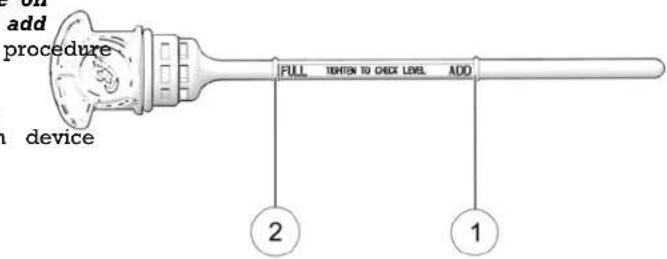
① ADD Mark
② FULL Mark
- Repeat steps 1-7 to ensure the level is within the safe range.
- Reinstall the dipstick securely.
TTIIRREESS
WARNING
Operating the motorcycle with incorrect tires, incorrect pressure or excessively worn tires could cause loss of accident. Under inflation can cause a tire to overheat a tire failure. Only use tires approved by INDIAN MO for the model of the motorcycle. See your dealer information. Use of unapproved or an improperly mixed rear tire can result in decreased handling performance stability, potentially leading to reduced control of the m Always maintain proper tire pressure as recommended rider's manual and on safety labels.
TTIIRREE PPRREESSSUURREE
Improper tire pressure can result in irregular tire wear, tireincidul reduced fuel economy and a poor riding experience. It can also affect handling and stopping ability.
Slow tire pressure loss over time is normal for a functional tire. Although a tire pressure monitoring system (TPMS) will alert the user to a low pressure condition (if equipped), always inspect tire pressure and condition before each ride.
Check tire pressure before riding, when the tires are cold. This will provide the most accurate reading, as riding warms the tires and increases tire air pressure. Tires remain warm for at least 3 hours after a ride. Do not adjust tire pressure immediately after riding. As tires cool, the pressure will drop and result in underinflation. Always check and adjust tire pressure when tires are cold.
Using supplied air pressure gauge, adjust tire pressure to the recommended pressure. See page 122.
TTIIRREE CCOONNDDIITTIIOONN
Inspect the tire sidewalls, road contact surface and tread base. And inspection reveals cuts, punctures, cracks or other wear or MOTORCYCLE, replace the tire before riding. Only use tires approved for more motor MOTORCYCLE for the model of the motorcycle. See your front dealer for more information. Use of unapproved or an improper and fixed front and rear tire can result in decreased handling motor performance and stability, potentially leading to reduced control in the motorcycle.
TTIIRREE TTRREEAADD DDEEPPTTHH
Measure the tread depth near the center of the tread on both See page 121. Replace any tire with a tread depth of less than tire incluile (6 mm).
FFRROONNTT BBRRAAKKEE FFLLUUIIDD LLEEVVEE
- Bring the motorcycle to the fully upright position. Position handlebars so that the fluid reservoir is level.
- View the fluid level through the sight glass fluid should be clear. Replace cloudy or contaminated fluid.

- The fluid level should be above the minimum indicator in the sight glass.
VEE the fluid level is low, inspect brake pads as outlined 118. If pads are not worn beyond the service limit, inspe the brake system for leaks. Check for signs of brake fluid le around hoses, fittings, reservoir, and brake calipers.
- Add brake fluid if necessary. See page 116.
FFRROONNTT BBRRAAKKEE LLEEVVEERR
- Pull the front brake lever toward the handlebar and hold lever should move freely and smoothly. The lever should firm and continue to feel firm until released.
- Release the lever. It should return to its rest position qui when released.
- If the front brake lever fails to perform as stated, service brake lever before riding.
RREEAARR BBRRAAKKEE PPEEDDAALL
- Press downward on the rear brake pedal. It should move and smoothly. The pedal should feel firm and continue to firm until released.
- Release the pedal. It should return to its rest position qu mark when released.
- If the rear brake pedal fails to perform as stated or trav far before beginning to engage the brake, service the bra before riding.
RREEAARR BBRRAAKKEE FFLLUUIDD LLEEVVBBRAAKKEE LLIINNEESS
The rear brake fluid reservoir is located near the rear brakesppetall brake hoses and connections for dampness or stains. View the reservoir level from the right side of the vehicle.from leaking or dried fluid. Tighten any leaking connections to
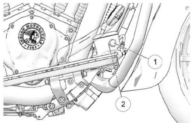
-
Position the motorcycle on level ground in the fully upright position.
-
View the brake fluid through the reservoir sight glass
-
The fluid should be clear. Replace cloudy or contaminated fluid.
-
The fluid level should be above the minimum indicator on the reservoir body. Add brake fluid as needed.
SSIIDDEE--SSTTAANNDD
- On level ground, straddle the motorcycle and bring it to the fully upright position.
-
Move the side-stand up to the stored position and down to fully extended position several times. It should move smooth and quietly. Make sure the return spring holds the side-stand tightly in place when the side-stand is in the stored position. Adjust or replace a loose spring.
-
Inspect the side-stand pivot bolt for looseness or wear. or replace a loose or worn bolt.
MMEECCHHAANNIICCAALL CCLLUUTTCCHH
-
Squeeze the clutch lever toward the handlebar and release it. It should move freely and smoothly, and it should return the rest position quickly when released. If the lever fails Tperform as stated, service the clutch lever before riding.
-
Periodically test the side-stand safety switch for proper it. It is operation. With the transmission in gear and brakes applied, the rest attempt to start the engine while the side-stand is down. The perform engine should NEVER start in any gear except neutral if the side-stand is down. If the engine starts during this test, see your dealer for service.
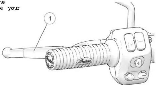
- Freeplay (gap) is the amount of lever movement from the position to the point of cable resistance. Clutch lever free should be 0.5-1.5 mm. Measure the gap between the clutch lever and the lever housing. See page 112. Adjust clutch freeplay if necessary.
TIP
The starter interlock switch is dependent on the clutch freeplay being set correctly to ensure activation of the safety switch.
FFAASSTTEENNEERRSS
- Inspect the entire motorcycle chassis and engine for damaged or missing fasteners.
- Tighten loose fasteners to the proper torque. See the MOTORCYCLE Service Manual or an authorized INDIAN MOTORCYCLE dealer or other qualified dealer.
NOTICE
Always replace stripped, damaged or broken fasteners riding. Use genuine INDIAN MOTORCYCLE fasteners of size and strength.
FFRROONNTT SSUUSSPPEENNSSIIOONN
Inspect the front forks for oil leaks or damage, and verify smooth suspension operation. See page 109.
SSTTEEEERRIINNGG
Level On level ground, straddle the motorcycle and bring it to the clutchly upright position. Turn the handlebars from stop to stop. The action should be smooth, but not loose.
- Make sure wires, hoses and control cables do not interfere smooth steering.
sRREEAARR SSUUSSPPEENNSSIIOONN
Check the rear shock absorber mounting and inspect for leaks. See your dealer for service if you discover leaks or malfunction any kind. See page 104.
SPRINGFIELD/CHIEFTAIN DARK HORSE/CHIEFTAIN/ROADMASTER only: Check rear shock absorber movement and air pressure to ensure the correct amount of suspension travel. See page 106.
before
equal

WARNING
Inadequate ground clearance could result in components contacting the ground, causing loss of control and serious injury or death. Always ensure ground clearance is at specification.
RREEAARR DDRRIIVVEE BBEELLTT
- Check drive belt tension. See page 99
NOTICE
The drive belt system must be cool, clean and dry to measure belt tension (deflection). Do not measure belt when the belt or drive system is wet or when it is immediately after riding).
The segments of the fuel gaugew the level of fuel in the fi tank. When the last segment clears, a low fuel warning is a All segments including the fuel icon will flash. Refuel prompt
- Check the drive belt for debris.
- Inspect drive belt condition. See page 99. If you discover cracks, broken teeth or frayed edges, replace the drive belt before riding. See the INDIAN MOTORCYCLE Service Manual or an authorized INDIAN MOTORCYCLE dealer can assist.
FFUUEELL LLEEVVEELL
For the most accurate reading, sit on the motorcycle and bring it to the upright position before turning it on.
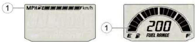
Cruiser Models Bagger and Touring Models
OOPPEERRAATTIIOONN
OOVVEERRVVIIIEEWW
The operation section of this manual describes how to ensure maximum performance and longevity through the proper care operation of your motorcycle.
Important areas covered by the operation section include:
- Engine Break-In
- Accelerating
- Fueling
- Braking
- Starting the Engine
- Stopping the Engine
- Shifting Gears
- Parking
• Using Cruise Control (if equipped)
[Non-Text]
TIP
Even if you're an experienced motorcycle operator or p read all of the safety information in this manual before the motorcycle. See page 9.
EENNGGIINNEE BBRREEAAKK--IINN
The engine break-in period for your motorcycle is the first 500 miles (800 km) of operation. During this break-in period, critical engine parts require special wear-in procedures so they seat and mate properly. Read, understand and follow all break-in procedures to ensure the long-term performance and durability of your engine.
NOTICE
Failure to properly follow the engine break-in procedures and outlined in this manual can result in serious damage to engine. Avoid full throttle operation and other conditions that may place an excessive load on the engine during the break period.
The more cautiously you treat your motorcycle during the brn period, the more satisfied you will be with its performance on. Overloading the engine at low RPM and/or running the prematurely at high RPM may result in damage to the piston and/or other engine components.
Observe the following precautions during the break-in period:
- Upon initial start-up, do not allow the engine to idle for 1 periods as overheating can occur.
passenger. • Avoid fast starts with wide open throttle. Drive slowly until e operating engine warms up.
- Avoid running the engine at extremely low RPM in higher (lugging the engine).
- Drive within the recommended operating speeds and gears.
OPERATION
OOPPEERRAATTIINNGG SSPPEEEEEDDSS AANND
| ODOMETER | BREAK-IN PROCEDURE | |
| MILES | KM | |
| 0-90 | 0-145 Do | not operate for extended periods above 1/3 throttle or at any one throttle position. Vary speed frequently. |
| 91-300 | 146-483 | Do not operate for extended periods above 1/3 throttle or at any one throttle position. Vary speed frequently. |
| 301-500 | 484-800 | Do not operate for extended periods above 3 throttle. |
| At 500 | At 800 | Perform the break-in maintenance outlined in the maintenance section of this manual. Break-in maintenance should be performed by a dealer. Break-in maintenance must include inspection, adjustments, fastener tightening and an engine or and filter change. Performing break-in maintena at the required odometer reading helps ensure engine performance, minimal exhaust emissions maximum service life of the engine. |
FFUUEELIINNGG
Always dismount the motorcycle and refuel on level ground with the sidestand down. Review the fuel warnings. Use only the recommended fuel. See page 162. Hold the nozzle while filling. Do not rest the weight of the nozzle and hose on the filler neck. Do not leave the nozzle unattended.
| JD GGEEAARRSS ⚠ WARNING |
| Overflows or spilled gasoline could contact a hot engine orexhaust system and cause a fire, which could result in seriousinjury or death. Do not allow gasoline to contact hot components. |
| WARNING |
| Always remove the fuel cap slowly and fill the fuel tank slowly to prevent spillage. Do not overfill the fuel tank. Leave space in the tank to allow for the fuel to expand. |
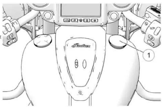
natural_image
Top-down view of a sports robot's front view showing steering wheel, dashboard, and control buttons (no text or symbols)- Turn the fuel @apounter-clockwise to remove it.
- Insert the fuel nozzle into the fuel tank filler neck. The nozzle-stop at the bottom of the filler neck will prevent over-insertion.
- Add fuel to the tank until it touches the bottom edge neck. The tank is full at this level.
- Always securely install the fuel cap before remounting motorcycle. To tighten the cap, turn it clockwise until t compresses onto the tank, then continue to tighten until ratchets several times.
NOTICE
Fuel can damage painted surfaces and plastic parts. If spills on the any part of the motorcycle, immediately with water or wipe it dry with a clean cloth.
- Repeat steps 3–5 five times.
- Move the engine stop/run switch to the RUN position.
- Start the engine.
8STTAARRTTIINNGG TTHHEE EENNGGIINNEE
The starter interlock system allows the engine to be started when the transmission is in neutral, or when the transmission remains with the clutch disengaged (clutch lever pulled in). The engine should NEVER start in any gear except neutral if the sidestand is down. See page 56.
TIP
gasoline rinse it off the motorcycle runs out of fuel, prime the system before attempting to restart the engine. See page 77.
PPRRIIMMIINNGG TTHHEE FFUUEELL SSYYSS
If the motorcycle runs out of fuel, prime the fuel system attempting to restart the engine.
- Perform the Pre-Ride Inspections. See page 63. Properly send any cargo.
before craddle the motorcycle and bring it to the fully upright position. Retract the sidestand.
- Fill the fuel tank.
- Turn the power switch on.
- Move the engine stop/run switch to the RUN position.
- Allow the fuel pump to run until it stops (about 2 seconds).
- Move the engine stop/run switch to the STOP position. 3. Move the engine stop/run switch to the RUN position.
When the electrical system is activated with either the power switch or the starter switch, the key fob must be within: See page 27.
TIP
OPERATION
- Shift the transmission to neutral.
- Apply the front brakes. Disengage the clutch (pull the lever fully toward the handlebar).
- The motorcycle may be electrically activated by pressing either the starter switch or power switch. Then with the closed, press and release the starter switch to start the The starter motor will crank until the engine starts, but than 3 seconds. If the engine does not start, wait five and try again.
-
If starting a COOL engine, DO NOT open the throttle while starting. Idle speed is computer controlled and idle speed adjust automatically depending on engine temperature and temperature. Allow the engine to warm up for one minute minimum at low RPM after starting. Do not run the engine 2500 RPM. If starting a WARM engine, DO NOT open the time while starting.
-
If either the check engine indicator or the low oil pressure indicator (or display) remains on after the engine starts, stop the engine immediately. Refer to the low oil pressure indicator/display information in the Low Oil Pressure Display section or the Indicator Lamps section.
throttle
NOTICE
no Operating an engine with a misfire or non-firing cylinder can seconds overheat the catalytic converter, which could result in catalytic converter damage and loss of emission control. DO NOT OPERATE the motorcycle if a misfire or non-firing cylinder exists
| TIP |
| Do not rev the engine or put the transmission in immediately after starting the engine. Allow the engine about 30 seconds after a warm start or at least one cold start (longer in cold weather). This will allow oil areas before the engine is put under load. |
NOTICE
Do not run the engine at high RPM with the clutch disengag the transmission in neutral. Maximum safe engine speed is 540 RPM. Never exceed the maximum safe RPM as this could resu serious engine damage.
NOTICE
The engine is air-cooled and requires unrestricted air flow to ensure proper operating temperature. Long periods of idling or traveling at very low speeds (such as during a parade) may overheat the engine, resulting in serious engine damage.
OPERATION
SSHHIFFTTIINNGG GGEEAARRSS
WARNING
Forced shifting (without clutch lever pulled in) could cause damage to the engine, transmission and drive train. Such could cause loss of control, which could result in serious death. Always pull the clutch lever fully toward the hand disengage the clutch before shifting gears.
This motorcycle is equipped with a six-speed transmission. Neutral is located between first and second gear.
Press downward on the toe lever to shift to a lower gear. Lift upward on the toe lever to shift to a higher gear. Release the clutch lever after each gear shift.
Shifting to neutral is easiest if the motorcycle is rolling slowly. To shift from first gear to neutral, gently lift the toe lever a half stroke.
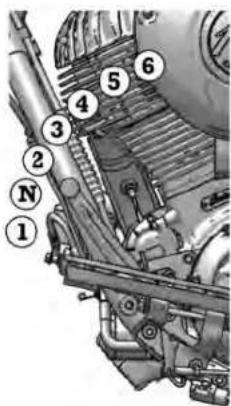
TIP
The transmission is in neutral if you can move the motorcycle forward or rearward freely without disengaging the clutch. If the cause power switch is ON, the neutral indicator illuminates when the damage transmission is in neutral.
injury or
shars to SSHHIFFTTIINNGG GGEEAARRSS WWHHILLEE SSTTA
To locate neutral when the motorcycle is stationary, use one of the following techniques to load and unload the transmission:
- With the clutch disengaged (lever pulled inward), shift into neutral while rocking the motorcycle forward and rearward.
- With the transmission in first gear, gently release the clutch until it just begins to engage. Apply upward pressure on the lever and quickly pull the clutch inward.
NOTICE
There is a Neutral indicator light on the instrument cluster.
SSHHIFFTTIINNGG GGEEAARRSS WWHHILLEE DDRRII
- Start the engine.
- With the engine at idle speed, apply the front brakes.
- Disengage the clutch (pull the clutch lever fully toward the handlebar).
- Push the toe lever downward until you feel it stop in first
OPERATION
- Release the brake lever.
- Simultaneously release the clutch lever while opening the throttle (rolling the throttle control grip rearward) in one smooth motion. As the clutch begins to engage, the motor will move forward.
- To shift to a higher gear, accelerate smoothly to the recommended shift point. See Recommended Shift Points chart With a quick motion, simultaneously close the throttle completely and disengage the clutch. Raise the toe shift until you feel it stop at the next gear. Simultaneously re clutch lever and open the throttle in one smooth motion,
TIP
Within the recommended speed ranges (see Recommended Points chart), you can downshift to slow the motorcycle increase power. You may want to downshift when climbing or passing. Downshifting also helps to decrease speed with combined with closing the throttle.
- Reduce speed before downshifting. Always downshift within recommended shift points.
- Use extreme caution when downshifting on wet, slippery or other low traction surfaces. Release the clutch lever very or cycle gradually in these conditions.
- Avoid downshifting in a curve. Downshift before entering the curve.
RREECCOOMMMMEEENNODEEDD SSHHIIFFTT PPOOIN
UOPPSSHHIFFTTIINNGG (AACCCCEELLEERRAATTIINNG)
- To shift to a lower gear (downshift), simultaneously pull clutch lever toward the handlebar and close the throttle. the toe shift lever downward until you feel it stop at the gear. Simultaneously release the clutch lever while opening throttle.

WARNING
Downshifting improperly could cause transmission damage, loss of traction and loss of control, which could result in serious injury or death.
| GEAR CHANGE | RECOMMENDED SPEED | ||
| Shift or to | 1 to 2 | 15 MPH (24 km/h) | |
| 2 to 3 | 25 MPH (40 km/h) | ||
| a hill | 3 to 4 | 35 MPH (56 km/h) | |
| ten | 4 to 5 | 45 MPH (72 km/h) | |
| 5 to 6 | 50 MPH (80 km/h) | ||
| GEAR CHANGE | RECOMMENDED SPEED | ||
| g the | |||
| 6 to 5 | 40 MPH (64 km/h) | ||
| 5 to 4 | 35 MPH (56 km/h) | ||
| 4 to 3 | 25 MPH (40 km/h) |
0000WWNNSSHHIFFTTIINNGG (ODEECCEELLEERRAATT)
OPERATION
| GEAR CHANGE | RECOMMENDED SPEED |
| 3 to 2 15 | MPH (24 km/h) |
| 2 to 1 10 | MPH (16 km/h) |
BBRRAAKKIINNGG
Always allow sufficient stopping distance so that brakes can applied gradually.
| NOTICE |
| Applying slightly more front brake than rear brake provides the best braking performance. |
- To slow the motorcycle with the brakes, close the throttle and apply the front and rear brakes evenly and gradually.
| NOTICE |
| If the anti-lock brakes engage during a braking event, will feel pulsing at the brake levers. Continue to app pressure to the brakes for the best stopping perform be |
- As the motorcycle slows, disengage the clutch, or downshift each time vehicle speed reaches a downshift point.
| ###WARNING |
| Braking improperly could result in loss of control, whresult in serious injury or death. Avoid braking abruptapply the brakes gradually, especially on wet, slipperylow traction surfaces. Avoid braking in a curve or turnmotorcycle to the upright position before applying the |
AACCCCEELLEERRAATTIINNGG
Accelerate by opening the throttle (rolling the throttle control g rearward). For even acceleration, open the throttle with a smoo continuous motion. When you reach the recommended speed for upshifting, shift up one gear.

WARNING
Accelerating abruptly could cause your body to shift it suddenly, which could result in loss of control. Acceler abruptly could also cause loss of control on low traction. Loss of control could result in serious injury or death. accelerate gradually, especially on wet, slippery or other traction surfaces.
SSTTOOPPPPIINNGG TTHHEE EENNGGIINNEE
Before stopping the engine, bring the motorcycle to a complete stop. Shift to neutral or disengage the clutch.

WARNING
Stopping the engine with the transmission in gear w motorcycle is moving could cause loss of rear wheel engine and transmission damage, which could cause control and serious injury or death. Always stop the of the motorcycle is fully stopped and the transmission is If the engine stops unexpectedly while the motorcycle guide the motorcycle to a safe location off the road from traffic. Turn the power switch off.
- When fully stopped, shift into neutral.
- Move the engine stop/run switch to the STOP position.
- Turn the power switch off.
UUSSIINNGG CCRRUUIISSEE CCOONNTTRROOLL
The cruise control switches are located on the right handleba rearward and this section and understand how to safely operate this operating before using the cruise control. On surfaces.
Always
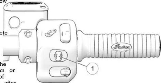
while the traction or loss of engine after in neutral. is moving,
and away Cruise control can be activated and adjusted from the right using the Cruise Control Switch
| Toggle Position Function | |
| Left | Set/Decelerate |
OPERATION
| Center Off/On | |
| Right Resume/Accelerate | |
WARNING
Improper operation of cruise control could cause loss and result in serious injury or death. Follow all cruise procedures carefully. Never use cruise control when ro wet or slippery. Do not use cruise control when riding congested traffic.
CCRRUUISSEE CCOONNTTRROOLLTTIIPPSS
• Cruise control can be set in gears 3-6.
- Vehicle speed must be above 20 MPH (32 km/h).
- Set speed will vary slightly in hilly terrain.
- Cruise control will not resume a pre-set speed if the re-acceleration or deceleration rate is too high or too low. example, resuming a set speed of 70 MPH (112 km/h) MPH (64 km/h), while in 6th gear, may cause cruise to disengage.
- Cruise control will not engage if brake lights are not of properly.
- The clutch or either brake must have been activated at least once since the engine was started for the cruise control to function.
SSEETT SSPPEEEDD
-
Press and release the center of the cruise control Tswitch amber cruise control indicator will illuminate in the instrumer cluster. Cruise control is enabled, but not set.
-
Accelerate to the desired speed and press left on the cruise control switch to activate cruise control. The green cruise operation control indicator lamp will illuminate. Cruise control is set to ds at the desired speed. in heavy or
RREESSUUMEE SSPPEEEEEDD
After disengaging the cruise control with the brake, throttle or clutch, press right on the cruise control switch to return to the speed.
AACCCCEELLEERRAATTEE
While cruise control is engaged, tap right on the cruise control switch to increase speed in approximately 1 MPH (1-2 km/h) increments. Press and hold the right on the cruise control swit to accelerate to a new set speed (resets when switch is released).
NOTICE
Operating you use the throttle to accelerate and then release it, the control will resume the previously set speed.
DDEECCEELLEERRAATTEE
While cruise control is engaged, tap and release left on the ranking on a slope is unavoidable, park with the front wheel control switch to decrease speed in approximately 1 MPH (up hill from the rear wheel. Place the transmission in first gear km/h) increments. Press and hold left on the cruise control position the motorcycle so that it is stable when it rests on to decelerate to a new set speed (resets when switch is redested). or to the minimum cruise speed of 20 MPH (32 km/h).
CCAANNCCCEELL CCRRUUIISSEE CCOONNTTRROOL
To temporarily cancel the cruise control and allow use of resume feature:
- Apply the brakes, or
• Pull the clutch lever in, or - Roll the throttle grip forward past the idle position
To cancel the cruise control and erase the set speed from press the cruise on/off switch.
PPAARRKKIINNGG
Choose a firm level surface to park the motorcycle.
- When fully stopped, shift into neutral.
- Stop the engine.
- Fully extend the sidestand.
- Turn the handlebars to the left and lean the motorcycle to the left until the sidestand firmly supports the motorcycle.
- Turn the power switch off and ensure the run/stop switch on the right-hand control is in the off position.
PARKING ON A SLOPE
If parking on a slope is unavoidable, park with the front wheel from the rear wheel. Place the transmission in first generation the motorcycle so that it is stable when it rests on redestated.
PARKING ON A SOFT SURFACE
If parking on a soft surface is unavoidable, place a sidestand footrest under the foot of the sidestand to provide a firm su. The sidestand footrest must be strong enough and large enough support the motorcycle's weight without sinking into the park surface.
Asphalt becomes soft in hot weather. A sidestand can sink in asphalt and the motorcycle may fall. When parking on asphalt hot weather, use a sidestand footrest.
| CAUTION |
| Hot engine and exhaust components can cause burns to can ignite a fire if exposed to flammable materials. At the motorcycle clear of flammable materials and where are not likely to contact hot components. |
MMAAIINNTTEENNAANNCCCEE
SSAAFFEETTYY DDUURRIINNGG SSEERRVVIICQEE Always Position and Motorcycle Exhaust Eye
WARNING
Failure to follow all recommended precautions and procedures could result in serious injury or death. Always heed all precautions and follow all operation, inspection and maintenance procedures outlined in this manual.
- Improperly installed or adjusted Hot engine and exhaust components can make the components can cause burns to motorcycle unstable or hard to skin and can ignite a fire if handle. Improperly installed exposed to flammable materials. electrical components can cause Always park the motorcycle clear engine or electrical system of flammable materials and failure. In either event, damage where people are not likely to or serious injury could result. Contact hot components. you do not have the time, looks, wear eye and face protection and expertise necessary to when using pressurized air. complete a procedure properly. Never start the engine or let it run please see your dealer for in an enclosed area. Engine service. exhaust fumes are poisonous and
- Review the safety-related maintenance information in the Safety Maintenance section. can cause loss of consciousness or death in a short time.
- During some procedures you may
- Before beginning any maintenance procedure, read the instructions for the entire procedure. Use potentially hazardous products such as oil or brake fluid. Always follow the instructions and warnings on the product packaging.
Always post the motorcycle systems may contain on a firm level surface before fibrous materials that could cause performing service. Make sure irritation to respiratory system, the motorcycle will not tip or eyes, and skin. While servicing, while elevated or while on thereplacing, or removing exhaust sidestand. See the Elevating the system, avoid inhalation, skin or Vehicle section for details. eye contact with fibers.
MAINTENANCE
RROOAADD TTEESSTTSS
Before returning the motorcycle to regular use after perform service, road test it in a safe environment. Pay special at the proper fit and operation of all serviced components. Make corrections or additional adjustments necessary to ensure safe vehicle performance.
MMAAJJOORR MMAAIINNTTEENNAANNCCCEE
Major repairs typically require technical skills and specially designed tools. Emission system service requires special tools training and should be performed by your dealer. See the MOTORCYCLE Service Manual or an authorized INDIAN MOTORCYCLE dealer or other qualified dealer.
BBRREEAAKK--IINN MMAAIINNTTEENNAANNCCÉE
Perform the break-in maintenance procedures when the motorcycle's odometer registers 500 miles (800 km). Please see your authorized dealer for this service.
Performing the break-in maintenance will help ensure optimum engine performance for the entire service life of the engine. Your dealer will change engine oil, inspect all fluids and serviceable components, ensure that all fasteners are tightened and make other adjustments as needed.
PPEERRIIOODDIICC MMAAIINNTTEENNAANNCCCEE
Inspect, clean, lubricate, adjust and replace parts as necessary. When inspection reveals the need for replacement parts, use genuine INDIAN MOTORCYCLE parts available from your dealer. Record service and maintenance information on page 177.
NOTICE
Use of non-recommended lubricants and components can result in damage to the motorcycle. Damage resulting from the use take non-recommended products is not covered by warranty.
Perform maintenance at the specified intervals. Vehicles subjected to severe use must be inspected and serviced more frequently.
SSEEVVEERREE UUSSEE DDEEFFIINNIITIIOONN
• INDEAN speed operation for extended periods
- low speed operation for extended periods
• operation in dusty or otherwise adverse conditions
operation in cold weather (temperatures below freezing)
PPEERRIIOODDIICC MMAAIINNTTEENNAANNCCCEE TTAABBLLEE
| Odometer Reading in Miles (Kilometers) | ||||||||||||||||||||||
| ComponentSee table key below | 500(800) | 2,500(4,000) & ever thereafter5,000(8,000) | 5,000(8,000) | 10,000 | 15,000 | (24,000) | 20,000 | (32,000) | 25,000 | (40,000) | 30,000 | (48,000) | 35,000 | (56,000) | 40,000 | (64,000) | 45,000 | (72,000) | 45,000 | (80,000) | ||
| Engine | Key Fob Battery * | - | - | - | - | - | - | - | - | - | - | |||||||||||
| Engine CompressionSee page 141 | I | - | - | I | - | I | - | I | - | I | - | I | ||||||||||
| Engine Oil & Filter*See page 94 | R | - | R | R | R | R | R | R | R | R | R | R | ||||||||||
| Crankcase Vent | I | I | I | I | I | I | I | I | I | I | I | I | ||||||||||
| Engine Mount Fasteners | I - | - | - | - | - | - | - | |||||||||||||||
| Oil Lines/Oil System Inspection (if equipped) | I | I | I | I | I | I | I | I | I | I | I | I | ||||||||||
| Air FilterSee page 96 | I | I | I | I | R | I | I | R | I | I | R | I | ||||||||||
| Exhaust SystemSee page 142 | I | I | I | I | I | I | I | I | I | I | I | I | ||||||||||
| Spark Plugs | I | - | I | R | I | |||||||||||||||||
| Maintenance Key: I = Inspect, clean, adjust, correct or replace if necessary; P = Perform; R = Replace/RebuildL = Lubricate w/ proper lubricant; * = Replace at specified interval or annually; ** = Replace as specified or every 2 years | ||||||||||||||||||||||
MAINTENANCE
| ComponentSee table key below | 500 (800) | 2,500 (4,000) & every 5,000 (8,000) | 5,000 (8,000) | 10,000 (16,000) | 15,000 (24,000) | 20,000 (32,000) | 25,000 (40,000) | 30,000 (48,000) | 35,000 (56,000) | 40,000 (64,000) | 45,000 (72,000) | 50,000 (80,000) | |||||||||||
| Chassis | Battery/ConnectionsSee page 132 | I | I | I | I | I | I | I | I | ||||||||||||||
| Brake Fluid** I I R I R I R I R | I R | ||||||||||||||||||||||
| Brake Lines/Brake PadsSee page 70 | I | I | I | I | I | I | I | I | |||||||||||||||
| Clutch CableSee page 113 | I | - | I | L | I | L | I | I | L | L | |||||||||||||
| Clutch Lever (Mechanical)See page 112 | L | - | I | L | I | L | I | I | L | L | |||||||||||||
| Diagnostic Codes I I I I I I I I I I | I | I | |||||||||||||||||||||
| Drive Belt (Rear)See page 73 | I | I | I | I | I | R | I | I | I | ||||||||||||||
| Drive Belt Tension Adjustment I | - | I | See dealer or service manual for adjustment at indicated intervals and with each tire change | ||||||||||||||||||||
| Maintenance Key: I = Inspect, clean, adjust, correct or replace if necessary; P = Perform; R = Replace/RebuildL = Lubricate w/ proper lubricant; * = Replace at specified interval or annually; ** = Replace as specified or every 2 years | |||||||||||||||||||||||
MAINTENANCE
| ComponentSee table key below | 500 (800) | 2,500 & every thereafter | (8,000) | 5,000 | (8,000) | 10,000 | (16,000) | 15,000 | (24,000) | 20,000 | (32,000) | 25,000 | (40,000) | 30,000 | (48,000) | 35,000 | 40,000 | (64,000) | 45,000 | (72,000) | 50,000 | (80,000) | ||
| Chassis | Electrical Equipment/Switches I I I I I | I | I | I | I | I | I | |||||||||||||||||
| Evaporative Emission Control System equipped) | I | I | I | I | I | I | I | I | I | I | ||||||||||||||
| FastenersSee page 142 | I | I | I | I | I | I | I | I | I | I | ||||||||||||||
| Front Brake LeverSee page 69 | L | I | L | L | L | L | L | L | L | L | L | |||||||||||||
| ABS ComponentsSee page 119 | I | I | I | I | I | I | I | I | I | I | ||||||||||||||
| Front Fork Oil**See page 109 | I | I | I | R | I | I | R | I | I | R | I | |||||||||||||
| Maintenance Key: I = Inspect, clean, adjust, correct or replace if necessary; P = Perform; R = Replace/RebuildL = Lubricate w/ proper lubricant; * = Replace at specified interval or annually; ** = Replace as specified or every 2 years | ||||||||||||||||||||||||
MAINTENANCE
| ComponentSee table key below | 500 (800) | 2,500 (4,000) & every 5,000 (8,000) | 5,000 (8,000) | 10,000 (16,000) | 15,000 (24,000) | 20,000 (32,000) | 25,000 (40,000) | 30,000 (48,000) | 35,000 (56,000) | 40,000 (64,000) | 45,000 (72,000) | 50,000 (80,000) | |||||||||||
| Chassis | Front Fork/AxleSee page 109 | I | I I | I I | I I | I I | I | I I | I | ||||||||||||||
| Fuel System/Lines/Fittings I I I I I I | I I | I I | I I | ||||||||||||||||||||
| Fuel FilterSee page 96 | - | - - | - - | - - | - - | - - | - - | R | |||||||||||||||
| Gear Shift Lever I I I I I I I I I | I | ||||||||||||||||||||||
| HeadlampSee the Headlight Aim Inspection section. | I | I I | I | - | I | - | I | - | I | - | I | ||||||||||||
| Rear Suspension Rocker I I I I L I | L | I I | L | ||||||||||||||||||||
| Rear Shock UnitSee page 72 and page 104 | I | I I | I I | I I | I I | I I | I I | R | |||||||||||||||
| Maintenance Key: I = Inspect, clean, adjust, correct or replace if necessary; P = Perform; R = Replace/RebuildL = Lubricate w/ proper lubricant; * = Replace at specified interval or annually; ** = Replace as specified or every 2 years | |||||||||||||||||||||||
MAINTENANCE
| ComponentSee table key below | 500 (800) | 2,500 (4,000) & every thereafter | (8,000) | (8,000) | 10,000 | (16,000) | 15,000 | (24,000) | 20,000 | (32,000) | 25,000 | (40,000) | 30,000 | (48,000) | 35,000 | (56,000) | 40,000 | (64,000) | 45,000 | (72,000) | 50,000 | (80,000) | ||
| Chassis | Rear Wheel AlignmentSee page 120 | I | I | I | I | I | I | I | I | I | ||||||||||||||
| Rear Brake PedalSee page 114 | I | I | I | I | I | I | I | I | I | |||||||||||||||
| Road TestSee page 142 | P | P | P | P | P | P | P | P | P | P | ||||||||||||||
| Sidestand/Sidestand Safety SwitchSee page 70 | L | I | I | I | I | L | I | I | I | L | I | I | I | L | I | |||||||||
| Steering BearingsSee page 110 | I | I | I | I | I | I | I | I | I | |||||||||||||||
| Suspension Linkage, Rear | I | I | I | I | I | I | I | I | I | |||||||||||||||
| Maintenance Key: I = Inspect, clean, adjust, correct or replace if necessary; P = Perform; R = Replace/RebuildL = Lubricate w/ proper lubricant; * = Replace at specified interval or annually; ** = Replace as specified or every 2 years | ||||||||||||||||||||||||
MAINTENANCE
| ComponentSee table key below | 500 (800) | 2,500 (4,000) & every thereafter | 5,000 (8,000) | (8,000) | 10,000 | (16,000) | (24,000) | (32,000) | (40,000) | (48,000) | (56,000) | (64,000) | (72,000) | (80,000) | ||
| Swingarm/Rear AxleSee page 109 | I | I | I | I | I | I | I | I | I | 25,000 | 25,000 | 30,000 | 35,000 | 40,000 | 45,000 | |
| Throttle Body I I I I I I I I I I I | I | |||||||||||||||
| Throttle Control Grip L I L L L L L | L | L | L | L | ||||||||||||
| Tires/Wheels/SpokesSee page 120 | I | I | I | I | I | I | I | I | I | |||||||
| Maintenance Key: I = Inspect, clean, adjust, correct or replace if necessary; P = Perform; R = Replace/RebuildL = Lubricate w/ proper lubricant; * = Replace at specified interval or annually; ** = Replace as specified or every 2 years | ||||||||||||||||
ENGINE OIL/FILTER CHANGE
Change the engine oil at the intervals specified in the Per Maintenance Table beginning on page 89. Change the oil r frequently if the motorcycle is subjected to severe use, esp operation in cold weather. See page 88.
NOTICE
odirFailure to perform frequent oil changes during cold weather more operation can result in condensation forming. Freezing socially condensation can result in plugged oil lines and serious engir damage.
The total amount of oil required for the oil and filter change approximately 5.5 qts. (5.2 l). Follow all instructions carefully. Do not overfill.
MAINTENANCE
NOTICE
After an oil change, the low oil pressure indicator may when the engine is started. If this occurs, do not increase above idle speed until the indicator turns off. Operating idle speed could result in damage to the engine.
- Change the oil and filter when the engine is warm. If is cold, start the engine and allow it to run at idle for minutes.
-
Park the motorcycle with the sidestand down on a firm, level surface. If using a service lift, the motorcycle should be centered.
-
Clean the area around the scavenge area drain plug luminate storage area drain plug Place a drain pan under both drain se Ruos. RPM

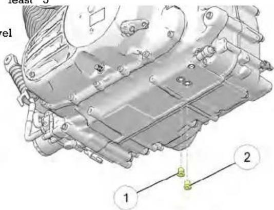
- Remove the drain plugs. Allow the oil to drain completely
- Install new sealing washers on the drain plugs. The sealir surfaces on drain plugs and engine should be clean and burrs, nicks or scratches.
MAINTENANCE
- Reinstall the drain plugs. Torque to specifications.
TORQUE
Drain Plug: 15 ft. lbs. (20 Nm).
CAUTION
Hot oil can cause burns to skin. Do not allow hot oil skin. Wear leather gloves when handling hot component
- Place oil pan beneath the oil filter. Using an oil filter turn the filter counter-clockwise to remove it.
- Using a clean dry cloth, clean the filter sealing surface engine.
- Lubricate the o-ring on the new filter with a film of froil. Check to make sure the o-ring is in good condition
- Install the new filter and rotate it clockwise by hand filter gasket contacts the sealing surface, then turn it an additional 3/4 to one full turn.
- Remove the dipstick. Add only 4.5 qts. (4.25 l) of the recommended oil at this step. Do not overfill.
- Reinstall the dipstick securely.
-
With the motorcycle in an upright, centered position, engine and run it at varied speeds up to 2500 RPM approximately 3 minutes.
-
Stop the engine and add an additional one quart (.95 l) of engine oil. Do not overfill. Overfilling can result in loss of engine performance and an oil-saturated air filter. Use a suction device to remove excess oil if overfilled.
- To ensure the oil level is within the safe operating range, re-check the oil level as outlined in page 66.
NOTICE
After an oil change, the low oil pressure indicator may illum: when the engine is started. If this occurs, do not increase I above idle speed until the indicator turns off. Operating above wrench, idle speed could result in damage to the engine.
- Dispose of used filter and oil properly.
- CHIEFTAIN MODELS / ROADMASTER: Reset the oil change life ash the engine the instrument gauge.
E F U W E E L L F F I I L L T E E R R
The fuel filter is attached to the electric fuel pump located in the fuel tank. See your authorized INDIAN MOTORCYCLE dealer other qualified dealer for replacement.
AAIIRR FFIILLTTEERR
The air box is located on the left side of motorcycle. Inspect stafiltertheften if riding in unusually wet or dusty conditions. Repla forthe filter at the intervals specified in the Periodic Maintenance Table on page 89.
- Remove the air box cover 📄scrawd remove the cover
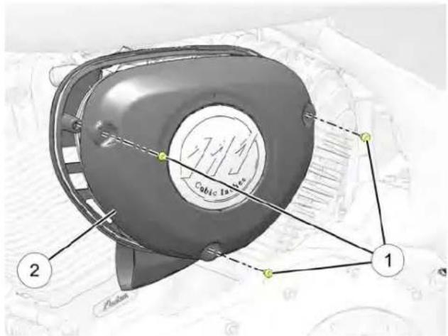
- Remove the three air filter screens remove the air filter assembly.
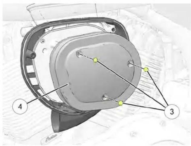
- Remove the air filter
- Clean the filter sealing surface on the backing plate.
- Verify that the air box cover seal is properly seated in groove around the outer edge of the air box backing pla
- Position the air filter assembly against the air box backing plate.
MAINTENANCE
- Reinstall the three screws. Torque to specification.
TORQUE
5 ft-lbs (7 Nm)
-
Reinstall the external air box cover and screws. Torque to specification.
-
Mix a few drops of mild dish soap with a cup of warm v
-
Use a soft nylon brush to clean the belt and sprocket teet the soapy water. Clean well in corner areas where road de and belt dust can collect.
-
Rinse the belt with clear water, then dry thoroughly.
TORQUE
7.4 ft-lbs (10 Nm)
NOTICE
A loose fitting cover or improperly installed filter element may allow debris to enter the engine which may cause premature engine wear.
RREEAARR DDRRIIVVEE BBEELLTT CCLLEEAANNIINNGG
NOTICE
Do not inspect or adjust drive belt tension when the belt or drive system is wet or hot. Improper adjustment will result.
Cleaning the drive belt will maximize belt and sprocket life and minimize drive line noise. Clean the belt at every tire change. Clean the belt more often if riding in dirty, dusty or high debris environments.
RREEAARR DDRRIIVVEE BBEELLTT CCOONNDDIITTIIOONN
Inspect the rear drive belt at the intervals specified in the Periodic Maintenance table. Replace the drive belt if it is cracked or has broken teeth. No matter its condition, the drive belt should be replaced at periodic intervals. See the INDIAN MOTORCYCLE Service Manual or an authorized INDIAN MOTORCYCLE dealer can assist.
DO NOT attempt to check belt tension if the belt has been exposed to rain or washing within a 24 hour period or if the vehicle has been run at operating temperature within the last four hours. Allow the vehicle to cool down to ambient temperature before measuring belt tension. Replace the drive belt and both sprockets as a set if the drive belt has over 5,000 miles (8,000 km) of service at the time of damage or failure.
MAINTENANCE
RREEAARR DDRRIIVVEE BBEELLTT WWEEAARR AANNAALLYYSSISS
 |  |  |  |
| Internal tooth cracks (hairline): OK to run, but monitor condition | External tooth cracks: Replace belt | Missing teeth: Replace belt | Chipping (not serious): OK to run, but monitor condition |
 |  |  |  |
| Fuzzy edge cord: OK to run, but monitor condition | Hook wear: Replace belt | Stone damage: Replace belt if damage is edge | Bevel wear (outboard edge on only): OK to run, but monitor condition |
DDRRIIVVEE BBEELLTT AADDJJUUSSTTMMEENNTT
IMPORTANT
Perform this procedure to achieve proper belt tension and alignment. Belt tension should be set before performing the alignment procedure.
BBEELLTT TTEENNSSIIOONN
WARNING
A drive belt that is not properly tensioned can cause drive line noise and damage the drive belt, causing possible belt failure and loss of control of the motorcycle.
NOTICE
Marks ① and ② are used as a reference for initial wheel alignment. Marks should be in roughly the same position on both left and right sides of wheel.
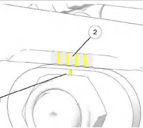
- Place the motorcycle in an upright position with the front clamped in a wheel vise.
- Make note of adjuster locations and ②.
- Raise the rear of the motorcycle so the rear tire can be rotated.
MAINTENANCE
- Loosen axle not and retighten to the ADJUSTMENT SPECIFICATION during the adjustment procedure.
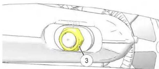
natural_image
Technical illustration of a mechanical component with a yellow bolt and numbered part (3), no readable text or symbols present.- Turn the RIGHT SIDE adjustet toutachieve proper belt tension.
- When belt tension is correct, check and adjust final wheel alignment as follows:
BBEELLTT AALLIIGGNNMMEENNTT
WARNING
A drive belt that is not properly aligned can cause drive l noise and damage the drive belt, causing possible belt failure and loss of control of the motorcycle.
NOTICE
To minimize change in belt tension, use LEFT SIDE adjuster c to make final adjustments to belt alignment.
TORQUE
Axle Nut Torque (ADJUSTMENT SPECIFICATION): 15 ft-lbs (20.3 Nm)
- Rotate the wheel BACKWARD. Tighten LEFT SIDE adjuster3. unfil necessary, loosen the axle nut and LEFT SIDE adjuster belt comes off inside sprocket flange during backward wheebelt just moves off the right flange and begins to track rotation. center of the driven sprocket flange during forward wheel
IMPORTANT
The belt should track to the center of the sprocket tooth when properly aligned. Sprocket teeth should be visible at both sides of the drive belt.
- Rotate the wheel in the FORWARD direction and verify sprocket teeth are still visible on both sides of the dr
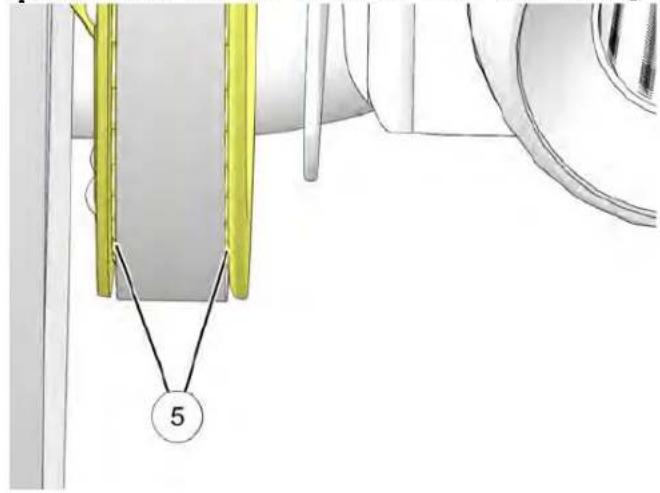
natural_image
Technical diagram showing a mechanical assembly with yellow components and a numbered label (5), no readable text or symbols present.| surface | NOTICE |
| on't may be necessary to loosen the axle nut and tap the lethe axle to ensure it moves forward when the adjusteloosened. The axle nut must be retightened to the ADJUSTM SPECIFICATION before proceeding.that | |
e belt
- Rear wheel alignment is satisfactory when the drive belt remains centered on driven sprocket during forward and backward wheel rotation. Sprocket teeth should be visible both sides of the drive belt.
- Verify that drive belt tension is still within specification.
- Tighten rear axle nut to FINAL specification.
TORQUE
Axle Nut Torque (FINAL TIGHTENING):
65 ft-lbs (88.0 Nm)
- Pump rear brake pedal several times to reset brake pad distance.
- Verify wheel rotates smoothly and freely without drag whe brake pedal is released.
MAINTENANCE
RREEAARR SSHHOOCCKK PPRREELLOOAADD ((RRHIDDEE HHEELTOGHHTT)) fender directly over the center of the rear axle.
Periodically inspect rear shock preload. For the most comfortable ride and proper ground clearance, adjust preload if ride height is out of specification.
- Verify that tire pressure is at specification. See page 122.
- Secure the motorcycle in an upright position by clamping the front wheel in a wheel vise.
- Remove the right-hand saddlebag (if equipped).
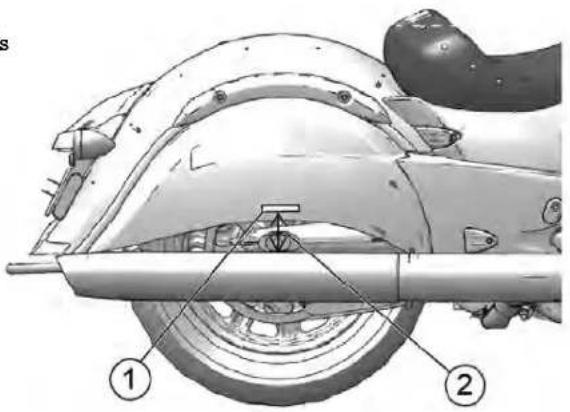
- Using a suitable lift, raise the motorcycle until the rear sho completely extended.
- Measure the distance(in millimeters) from the center of the rear axle to the bottom of the tape. Record the results as measurement M1.
-
Lower the motorcycle and remove the lift.
-
Load the motorcycle with all intended cargo. Wearing your riding gear, bring the motorcycle to the upright position and sit on the operator's seat. If you plan to carry a passenger, have the passenger (with riding gear) sit on the passenger seat. REAR SHOCK PRELOAD (RIDE HEIGHT) ADJUSTMENT APPLIES TO: CHIEF MODELS
- Have an assistant measure in the same location. Record the results as measurement M2.
- Subtract measurement M2 from M1. The result is the measured rider sag. (M1-M2=Sag). Adjust preload as needed.
| RECOMMENDED SUSPENSION SAG | ||
| CHIEF MODELS 35mm | 1.375 in. (1 3/8) | |
| SPRINGFIELD MODELS | 45mm 1.75 in. (1 3/4) | |
| CHIEFTAIN MODELS 45mm | 1.75 in. (1 3/4) | |
| ROADMASTER MODELS | 45mm 1.75 in. (1 3/4) | |
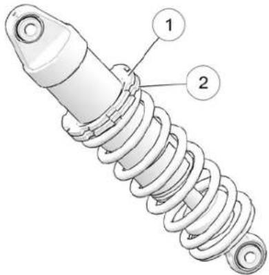
- Park the motorcycle with the sidestand down on a firm, surface. Remove all riders and cargo.
- Remove the seat. See page 126.
TIP Using the INDIAN MOTORCYCLE spanner wrench PV-46993 w make rear suspension adjustment significantly easier
MAINTENANCE
- The upper spanner nut on the shock is the. The nut lower spanner nut is the adjuster hooten the lock nut turning it counter-clockwise (as viewed from the top of with the spanner wrench.
- Spray a light lubricant on the adjuster nut where it is spring.
- Adjust shock preload by rotating the adjuster clockwise viewed from the top of shock) to INCREASE preload (if counter-clockwise to DECREASE preload (softer).
- Recheck the preload measurement after adjusting.
- Tighten the lock nut securely against the adjuster nut.
- Reinstall the seat.
SSHHOOCCKK AAIIRR PPRREESSSSUURREE AADDJJUUSSTTMMEENNTT
APPLIES TO: SPRINGFIELD/CHIEFTAIN CCLLAASSSSIICC/RROOAADMAASSTTEERR
| CAUTION |
| Air pressure increases VERY quickly when using pressuWear eye and face protection. |
For riding comfort and to ensure proper ground clearance, adjust rear shock air pressure. Refer to the label located on the insi shockleft side cover. The label shows recommended pressures based on potential load weights. Always inspect and adjust shop preload (ride height) based on your actual load weight, in addition to adjusting shock air pressure.
Follow these guidelines when adjusting:
(firm) Park the motorcycle with the sidestand down on a firm, leve surface. Remove all riders and cargo.
• DO NOT exceed 150 PSI (1034 kPa) in the shock.
- Use the INDIAN MOTORCYCLE Air Pump and Gauge (P/N PV-48909). Follow the instructions on the following pages.
If the recommended air pump is not available, use a gauge a 150 PSI (1034 kPa). After using the alternate gauge, remove it quickly to minimize leakage. Expect to lose up to 5 PSI (34 l) with each pressure check. Use only a dry air source, such as a system with a water separator or air line dryer, to prevent moi from entering the shock.
| AIR SUSPENSION ADJUSTMENT | ||||
| TOTAL CARGO & OCCUPANT WEIGHT (lbs) | AIR PRESSURE (psi) | MAX PRESSURE: 150 PSI | ||
| NO TRUNK | LEATHER TRUNK | PAINTED TRUNK | ||
| 0 | 0 | 0 | 0 | SELECT PRESSURE CORRESPONDING TO TOTAL CARGO AND OCCUPANT WEIGHT. REMOVE ALL |
| 150 | 0 | 0 | 0 | |
| 175 0 0 | 10 | PASSENGERS AND CARGO BEFORE SETTING/CHECKING SHOCK PRESSURE. SET PRESSURE WITH BIKE ON SIDE STAND. | ||
| 200 0 10 | 23 | |||
| 225 10 23 | 30 | |||
| 250 23 30 | 38 | |||
| 275 30 38 | 48 | |||
| 300 38 48 | 60 | |||
| 325 48 60 | 71 | |||
| 350 60 71 | 85 | |||
| 375 71 85 | 100 | |||
| 400 85 100 | 122 | |||
| 425 100 | 122 134 | |||
| 450 122 | 134 145 | |||
| 475 134 | 145 N/A | |||
| 500 145 | N/A N/A | |||
LOW SHOCK PRESSURE MODELS
| AIR SUSPENSION ADJUSTMENT | |||
| TOTAL CARGO & OCCUPANT WEIGHT (lbs) | AIR PRESSURE (psi) | MAX PRESSURE: 150 PSI | |
| NO TRUNK | PAINTED TRUNK | ||
| 0 | 0 | 0 | SELECT PRESSURE CORRESPONDING TO TOTAL CARGO AND OCCUPANT WEIGHT. REMOVE ALL PASSENGERS AND CARGO BEFORE SETTING/CHECKING SHOCK PRESSURE. SET PRESSURE WITH BIKE ON SIDE STAND. |
| 150 | 0 | 0 | |
| 175 | 0 | 10 | |
| 200 | 0 | 17 | |
| 225 | 10 24 | ||
| 250 | 17 45 | ||
| 275 | 24 65 | ||
| 300 | 32 85 | ||
| 325 | 40 97 | ||
| 350 | 52 | 110 | |
| 375 | 67 | 119 | |
| 400 | 82 | 127 | |
| 425 | 98 | 136 | |
| 450 | 114 | 145 | |
| 475 | 130 | N/A | |
| 500 | 145 | N/A | |
MAINTENANCE
SSHOOCCKK AAIIRR PPRREESSSUURREE ((RRHDBDEE KINEENGOCHHTT)) AADDJJUUSSTTMMEENNTT The air fitting. Read the air pressure on the gauge.
AAPPPPLLIEESS TTOO:: SSPPRRIINNGGFFIET MMOODDEELLSS//RROOAADDMMAASSTTEERR
- Park the motorcycle with the sidestand down on a firm, level surface. Remove all riders and cargo.
- Remove the left side cover. Remove the cap from the air fitting ①.
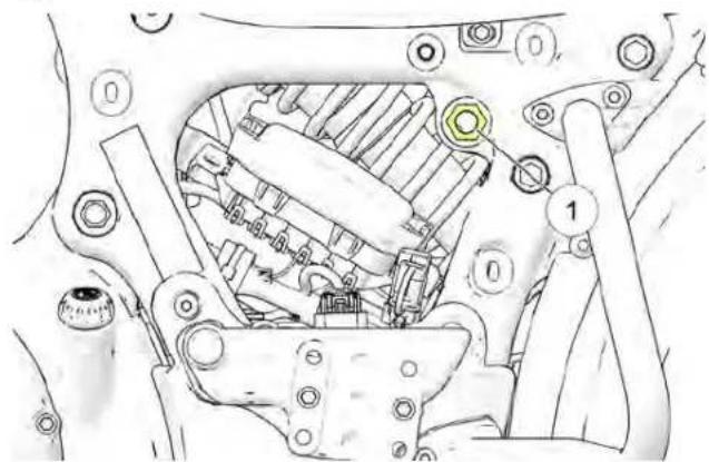
natural_image
Technical diagram of a mechanical assembly with numbered components (no readable text or symbols)-
Determine the recommended rear shock air pressure. Refer to the label located on the inside of the left side cover.
-
To reduce air pressure, push the bleed button on the gauge. Bleed pressure in small amounts until the desired pressure is attained.
- To increase pressure, pump the handle until pressure increases to the desired amount.
CAUTION
DO NOT exceed 150 PSI (1034 kPa) in the shock.
- Remove the hose from the air fitting and reinstall the cap.
TIP
Expect to lose up to 5 PSI (34 kPa) with each pressure check.
- Repeat the preload inspection to verify proper preload. See page 104.
SSWWIINNGG AARRMM//RREEAARR AAXLLEE IFRSSBNECQFFDIORMK//SSUUSSPPEENNSSIIC
- Sit in the operator's seat and slowly bounce the rear suspension. I am the motorcycle on the sidestand and inspect the fro a few times. Make sure the suspension moves freely withoutorks. If fork oil is present on the outer tube, do not ride binding. Listen for abnormal noises. motorcycle. See your dealer for service before operating. If
- Elevate and support the motorcycle with the rear tire slightly off is present around the fork scanner tubes, replace the floor. See page 142
CAUTION
Make sure the motorcycle is stable when elevated. Injury may occur if the motorcycle tips or falls.
- Grasp the rear wheel and attempt to move the wheel side-to-side. If there is movement at the front of the swingarm or in the axle area, see your dealer for service.
- With the transmission in neutral, slowly rotate the rear wheel. If the wheel does not rotate smoothly, see your dealer for service.
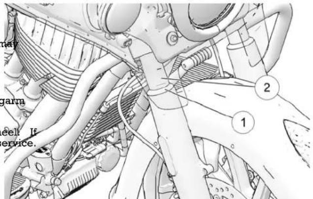
- Clean the fork tubes to remove bugs, tar or buildup whi cause seal wear or leakage. Inspect the outer surfaces of inner fork tubes for scratches or damage from foreign obj
MAINTENANCE
-
Straddle the motorcycle and bring it to the fully upright4. position. Apply the front brake and push downward (hard) the handlebars several times. The front suspension should operate smoothly and quietly.
-
Fork oil condition and level affects front suspension performance and internal component wear. Replace fork oil the recommended intervals. Special tools are required to perform this procedure. See the INDIAN MOTORCYCLE Service Manual or an authorized INDIAN MOTORCYCLE dealer can assist.
If steering binds, feels rough or uneven, or if movement is detected at the steering stem, see your dealer for service.
- Rotate the front wheel and inspect for smooth rotation of fr-wheel bearings. If roughness or unusual sounds are present, see your dealer for service.
Turn handle bars full right or left and hold against the for Attempt to move front wheel side-to-side. If movement is observed, see your dealer for service.
SSTTEEEERRIINNGG HHEEAADD IINNSSPPEECCTTIOONN
CCRRAANNKKCCAASSEE BBRREEAATTHHEERR HH
- Elevate and support the motorcycle with the front tire slide off the floor. See the Elevating the Motorcycle section for details.
CITTHODNN breather hoses along their length and at both end. Make sure hoses are not restricted, kinked, cracked or otherwise damaged. Replace any worn or damaged hoses.
CAUTION
Make sure the motorcycle is stable when elevated. Injury occur if the motorcycle tips or falls.
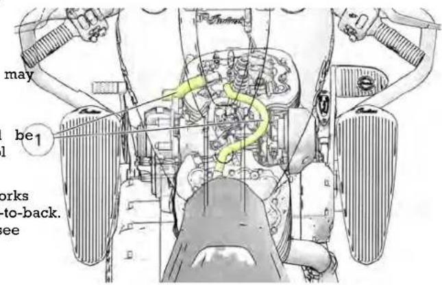
-
Turn the handlebars from stop to stop. The action should smooth but not loose. Make sure wires, hoses and control cables do not interfere with smooth steering.
-
Position the front wheel straight ahead. Grasp the front forks near the front axle and attempt to move the wheel front-to-back. If there is front-to-back movement at the steering head, see your dealer for service.
EEVVAAPPOORRAATTIIVVEE EEMMISSSSIIOONNFOOOOILNTSGRDGSCTESYMMGSCODIMMPPONNEE ((CCAALLIFFOORRNNIIAA AANNDD IINNTTEERRNNAATTHIQONNAALLMMOODDEFELLSS))
- Inspect all evaporative emission control system hoses and2. Inspect hose connections at the fuel at a hkat the fuel rail connections. Make sure all connections are tight and locked for dampness or stains from leaks. The tank connection fo
- The canister is located under the rear fender. Make sure it is securely fastened to the mounting bracket.
- The fuel system is under pressure and caution must be
- Inspect connections at the evaporative emissions canister to ensure they are secure. The vent line coming from the tank should be removed to the block part. The pump line should be used to maintain the safety of the motorcycle dealer can assist.
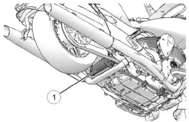
natural_image
Technical diagram of a car engine bay with labeled component (1), showing internal components and structural lines without any readable text or symbols.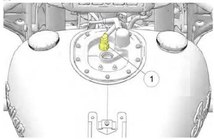
natural_image
Technical diagram of a mechanical component with labeled parts (no readable text or symbols)MAINTENANCE
TTHHRROOTTTTLLEE CCOONNTTRROOLL IINNSSPRODEESIITOMNDD LLUUBBRIICCAATTIIOON!
- With the engine OFF, rotate the throttle control grip fully open and then release it. It should rotate smoothly from the rest. Periodically lubricate the sidestand bushing. See page 70 for sidestand inspections.
position to the completely open position. It should return to the rest position quickly when released.
- Service the throttle system if throttle operation is not smbot position the handlebars in the straight-ahead position before if throttle grip does not return properly. See the INDIAN measuring clutch lever freeplay.
MOTORCYCLE Service Manual or an authorized INDIAN MOTORCYCLE dealer can assist.
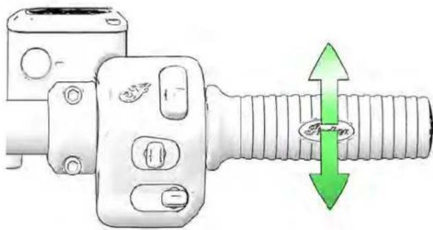
natural_image
Technical illustration of a mechanical component with a green double-headed arrow indicating rotational motion (no text or symbols)MEECCHHAANNIICCAALL CCLLUUTTCCHH LLEEVV
- The clutch cable adjuster nut is located alongside the left down-tube. While holding the cable, slide the rubber protective cover away from the lock nut. Loosen the lock nut
- Turn the cable adjuster inward or outward until clutch lever freeplay is 0.5-1.5 mm as measured at the clutch perch.
- While holding the cable, tighten the adjuster lock nut secure
- Verify that the safety switch activates properly. The engine should not start in gear with the clutch lever released. Never test the clutch safety switch by attempting to start the motorcycle in gear unless the rear wheel is raised off the ground.
TIP
The starter interlock switch is dependent on the clutch lever freeplay being set correctly to ensure activation of the clutch safety switch.
MMEECCHHAANNIICCAALL CCLLUUTTCCHH LLEEVEERRLLUUBBRRHCCAATTHOGNN
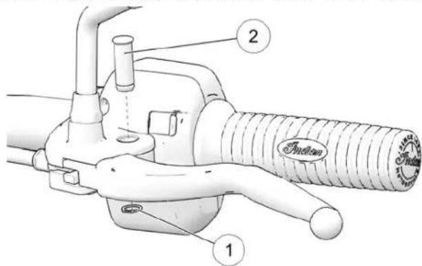
- The clutch cable adjuster nut is located alongside the down-tube. Slide the rubber protective cover away from adjuster. Loosen the lock nut.
- Turn the cable adjuster completely inward to provide lever freeplay.
- Remove the clutch lever Ⓞ-clind pin ^2 . Disconnect the clutch cable from the clutch lever.
Lubricate the clutch lever and pin with moly assembly gre or all-purpose grease.
NOTICE
During installation of the lever, be aware of the internal switch. Improper assembly can cause damage to the switch
- Reconnect the clutch cable. Reinstall the lever C-clip and
- Adjust clutch lever freeplay. See page 112.
- Tighten the adjuster nut and slide the protective cover ov adjuster.
MMEECCHHAANNIICCAALL CCLLUUTTCCHH CCAA
Lubricate control cable ends at the intervals recommended in Periodic Maintenance table.
NOTICE
theExternal casings are factory-lubricated. Additional lubrication could be detrimental to cable performance.
Verify proper routing and smooth movement. Inspect for damage to the external casing, and inspect exposed cable wire for f- kinks or corrosion. Replace any damaged, sticky or sluggish cable.
MAINTENANCE
- Disconnect the cable at the clutch lever and at the prin cover.
- Lubricate the barrel ends with all-purpose grease.
- Reconnect the cable and adjust freeplay as needed.
BBRRAAKKEE HHOOSSEESS//CCOONNNNEECCT
Inspect all brake hoses and connections for dampness or st from leaking or dried fluid. Tighten any leaking connections replace components as necessary. See the INDIAN MOTORCYO Service Manual or an authorized INDIAN MOTORCYCLE dealer assist.
RREEAARR BBRRAAKKEE PPEEDDAALL
- Lubricate the pivot bushing at the intervals recommended the Periodic Maintenance Table beginning on page 89. A lubricate any time binding is evident. Use all-purpose gr
- Inspect brake pads as outlined in the Brake Pads sectio
BBRRAAKKEE FFLLUUIIDD PPRREECCAAUUTTIIDO

WARNING
Using the wrong fluid or allowing air or contaminants into the fluid system can damage the system seals or result in a malfunction that could lead to serious injury or death. Use on 4 brake fluid from a sealed container.
do not operate the front brake with the reservoir cover remo Find could overflow from the reservoir and allow air to enter CLE system. Air in the brake system could cause the brakes to can malfunction.
An over-full reservoir may cause brake drag or brake lock-up which could result in serious injury or death. Maintain brake at the recommended level. Do not overfill.
NOTICE
Brake fluid will damage painted surfaces and plastic parts. Always clean spilled brake fluid immediately with water and mild detergent.
RREEAARR BBRAAKKEE FFLLUUIIDD
- Remove the cover and diaphragm. The fluid level should
Change the brake fluid at the intervals recommended in the a Periodic Maintenance Chart on page . Always add brake fluid A from a new, unopened container. Always use the recommended fluid. See page 162.
- Position the motorcycle on level ground in the fully upright position.
- The rear brake fluid reservoir is located near the rear brake pedal. View the reservoir from the right side of the vehicle.
- Wipe the fluid container and the area around the reservoir cover with a clean cloth.
- If the fluid level is low, inspect brake pads as outlined on page 118. If pads are not worn beyond the service limit, inspect the brake system for leaks.
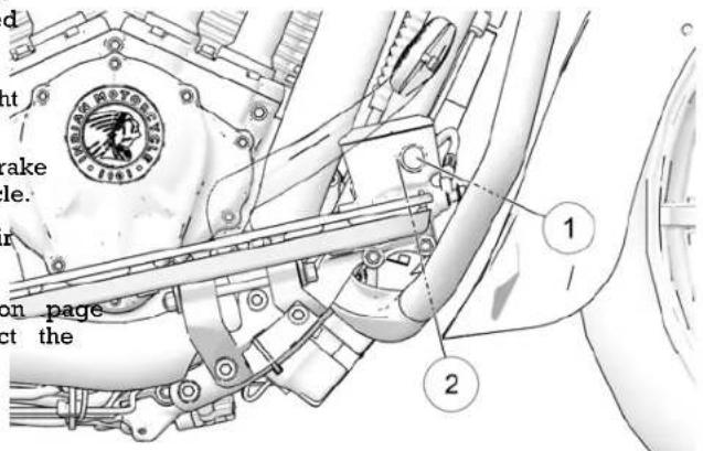
- Reinstall the cover and diaphragm.
- Wipe away any fluid spills. Check for signs of brake flui around hoses, fittings, reservoir, and brake calipers.
MAINTENANCE
FFRROONNTT BBRRAAKKEE LLEEVVEERR
- Lubricate the pivot (p) and brake lever hinge points at intervals recommended in the Periodic Maintenance Tab. Also lubricate any time binding is evident. Use all-purj grease.
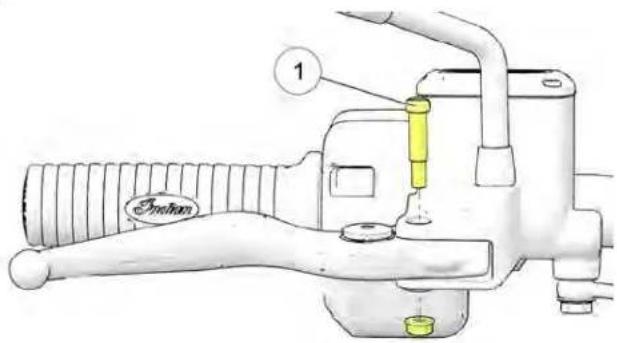
FFRROONNTT BBRRAAKKEE FFLLUUIDD
Change the brake fluid at the intervals recommended in the Periodic Maintenance Table. Do not attempt to change the anti-lock brake system fluid. Please see your dealer for this service. Always add brake fluid from a new, unopened container. Always use the recommended fluid. See page 162.
-
Position the motorcycle on level ground in the fully upright position. Position the handlebars so that the fluid reservoir is level. Wipe the fluid container and the area around the reservoir cover with a clean cloth.
-
If the fluid level is low, inspect brake pads as outlined on 118. If pads are not worn beyond the service limit, inspect brake system for leaks.
-
To add fluid, remove the reservoir cover screws. Remove the cover and diaphragm.
-
Inspect brake pads as outlined on page 118.
TORQUE
Pivot Pin: 4.9 ft lbs (6.6 Nm)
- The fluid level should be above the minimum indicator in the sight glass Add brake fluid as needed. Do not of
BBRRAAKKEE DDISSCC IINNSSPPEECCTTII00NN
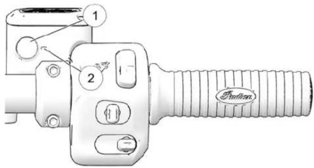
- Inspect brake disc for nicks, scratches, cracks or other damage. Inspect the thickness of each brake disc at four more locations around the disc. If any disc is worn to the minimum thickness at the thinnest point, or if a disc is damaged, see your dealer for replacement.
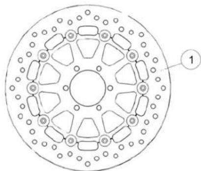
natural_image
Technical diagram of a circular mechanical component with multiple slots and mounting holes (no text or symbols)- Reinstall the diaphragm, cover and screws.
TORQUE
13 in-lbs (1.4 Nm)
NOTICE
Minimum Thickness: Front: 4.5mm; Rear 6.5mm Use a dial caliper to measure minimum thickness.
- Wipe away any fluid spills. Check for signs of brake fluid leaks
around hoses, fittings, reservoir and brake calipers. Check _2 , deterioration of hoses.
Clean discs if minor squeaks develop due to dirt or dust brake cleaner to a clean shop towel and wipe the discs. NOT allow brake cleaner to contact painted or plastic par Read all precautions on the label.
MAINTENANCE
BBRRAAKKEE PPAADDSS
Inspect each front brake pad on both sides of the front d Inspect each rear brake pad on both sides of the rear d brake pads when the thinnest point of the friction@material worn to 1.0 mm. Please see your dealer for this service.
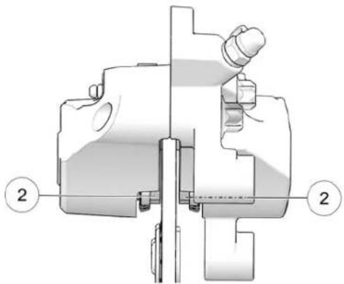
natural_image
Mechanical assembly diagram showing a valve or connector with two numbered parts (2), no text or symbols present.NOTICE
After replacing pads, allow up to 250 miles (500 km) in urban driving conditions (not highway cruising) to a to mate with new rotors. Brakes should be used free. During this time brake performance will be less effective using brakes harshly unless in an emergency. Brake will gradually increase during this seating period.
of operation low pads Use an inspection mirror, positioned at the front side of the quently caliper, to view the friction material. ve. Avoid efficiency Reinstall the caliper covers (if equipped).
When checking brake pad friction material thickness, check each brake caliper for dampness or stains from leaking or dried br. fluid. If inspection reveals signs of fluid leakage, do not operate the vehicle. See your dealer for service.
FFRROONNTT BBRRAAKKEE PPAADD IINNSSPPEECCT
- Remove the two acorn nuts (if equipped) one screw securing the protective caliper covers. Remove the covers.
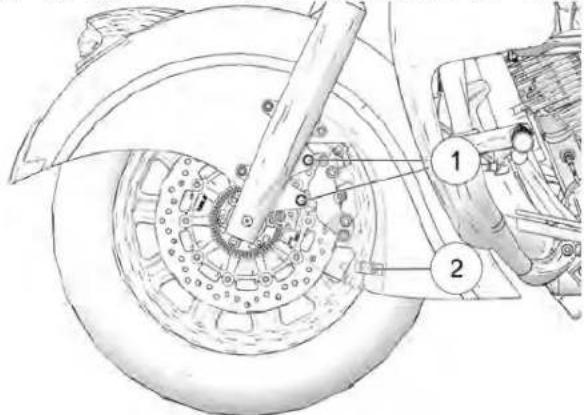
TORQUE
Acorn Nuts①: 18 ft-lbs (24 Nm)Caliper Cover Screw in-lbs (9.5 Nm)
RREEAARR BBRRAAKKEE PPAADD IINNSSPPEECCTTIDONE
- Position the motorcycle on the sidestand with the handlebarpossible, turned to the left.
- Use an inspection mirror, positioned at the front side of the caliper, to view the friction material. sensors ②. If contamination is observed, or if you are una visually inspect, slide a thin towel across the face of the between the sensor and the tone ring to remove any pot debris.
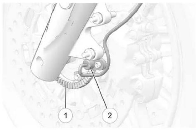
MAINTENANCE
WWHHEEEELL SSPPOOKKEESS ((IIFF EEQQUUIFPPPOOD)T WWHHEEEELL IINNSSTTAALLLAATT
Inspect both wheels for loose, bent, broken or missing spokes that front wheel is removed for any reason, it must be rein equipped). To identify loose spokes, grasp each spoke and in the correct rotating direction.
move it side to side or up and down. All spokes should be equally tight and have the same amount of flex. Tighten loose spokes and replace bent, broken or missing spokes (see an authorized dealer).
WARNING
Spokes adjusted or replaced improperly could distort the wheel, make the motorcycle difficult to handle, and cause loss of control.
WWHHEEEELL IINNSSPPEECCTTIOONN
Inspect both wheels for cracks or damage and replace damaged wheels promptly. Do not operate the motorcycle if wheels are damaged or cracked. See the INDIAN MOTORCYCLE Service Manual or an authorized INDIAN MOTORCYCLE dealer can assist.
WWHHEEEELL AALLIIGGNNMMEENNTT
Inspect rear wheel alignment at regular service intervals, whenever the rear wheel is removed and when the rear is adjusted. Please see your dealer for this service.
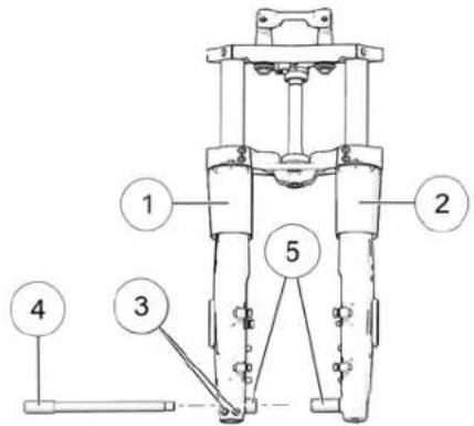
drive belt
① Right Fork Tube
② Left Fork Tube
③ Pinch Bolt 18–19 ft-lbs. (24.4–25.7 Nm)
④ Axle Bolt 52 ft-lbs. (70 Nm)
⑤ Wheel Spacers 0.925 in. (23.5 mm)
TTIIRREESS
! WARNING
Operating the motorcycle with incorrect tires, incorrect pressure or excessively worn tires could cause loss of accident. Under-inflation can cause a tire to overheat in a tire failure. Always use the correct size and ty specified by INDIAN MOTORCYCLE for your vehicle. I maintain proper tire pressure as recommended in the manual and on safety labels.
TTIIRREE RREEPPLLAACCEEMMEENNTT
NOTICE
On models equipped with a TPMS, the sensors are lo from the valve stem. Use caution when servicing tires, damaging a sensor, break the bead at the valve stem, and 270° from the valve stem as required.
Tires, rims, inertubes and air valves must be correctly matched by you may also use a depth gauge or an accurate ruler to make wheel rims. Use only the proper size tires specified with the same depth of the center tire tread on both front and rear teeth or higher load ratings. INDIAN MOTORCYCLE-recommended tires provide proper clearance between fenders, swingarm, drive belts and other components. See the Specifications chapter.
On models equipped with inertubes, inertubes MUST be replaced with new inertubes when tires are replaced. Use only the proper size inertubes.
WARNING
Mismatched tires, rims and air valves may result in damage tire bead during mounting or may allow the tire to slip off possibly resulting in tire failure.
PTIREE CCOONNDDIITTIIOONN
rider inspect the tire sidewalls, road contact surface, and tread bas cuts, punctures, and cracking. Replace damaged tires immediately. See the INDIAN MOTORCYCLE Service Manual or an authorized INDIAN MOTORCYCLE dealer can assist.
TTIIRREE TTRREEAADD DDEEPPTTHH
Replace any tire with a tread depth of less than 1/16 inch treated 180° Tread wear indicators are located in at least six places on to avoid circumference and become visible at a tread depth of then at 90° approximately 1/16 inch (1.6 mm). The tread wear indicators appear as a solid band across the tread.
You may also use a depth gauge or an accurate ruler to manage the same depth of the center tire tread on both front and rear tires
MAINTENANCE
TTIIRREE PPRREESSSUURREE
Always check and adjust tire pressure when tires are cold. Do not adjust tire pressure immediately after riding. Wait at least 3 hours after riding to check pressure. If pressure checked and adjusted while tires are warm, the pressure will drop as tires cool and result in under inflation. Adjust tire pressure as recommended for the total weight of your intended load (see tire pressure chart). For more information, refer to the manufacturing information label located on the front frame down tube.
WARNING
Do not exceed the maximum recommended inflation pressure to seat the bead. Tire or rim failure may result.
TTIIRREE PPRREESSSUURREE CCHHAARRTT
| LOCATION SIZE | BRAND TYPE | RECOMMENDED PRESSURE | |||
| LOADS UP TO 200 LBS. KG) | LOADS UP TO VEHICLE'S MAXIMUM LOAD CAPACITY | ||||
| Black Tires - ROADMASTER / ROADMASTER LE | |||||
| Front 130/90-B16 73H Dunlop Elite 3 36 psi | (248 kPa) | 36 psi (248 kPa) | |||
| Rear | 180/60-R16 80H | Dunlop | Elite 3 | 41 psi (283 kPa) | 41 psi (283 kPa) |
| White Wall Tires - CHIEF VINTAGE | |||||
| Front | 130/90-B16 67H | Dunlop | American Elite | 36 psi (248 kPa) | 36 psi (248 kPa) |
| Rear | 180/65-B16 81H | Dunlop | American Elite | 40 psi (276 kPa) | 40 psi (276 kPa) |
| Black Tires - SPRINGFIELD | |||||
| Front 130/90-B16 73H Dunlop Elite 3 46 psi | (317 kPa) | 46 psi (317 kPa) | |||
| Rear | 180/60-R16 80H | Dunlop | Elite 3 | 41 psi (283 kPa) | 41 psi (283 kPa) |
| Black Tires - CHIEF / CHIEF DARK HORSE | |||||
| Front 130/90-B16 73H Dunlop Elite 3 36 psi | (248 kPa) | 36 psi (248 kPa) | |||
| Rear | 180/65-B16 81H | Dunlop | American Elite | 40 psi (276 kPa) | 40 psi (276 kPa) |
| Black Tires - SPRINGFIELD DARK HORSE / CHIEFTAIN / CHIEFTAIN DARK HORSE / CHIEFTAIN LIMITED | |||||
| Front: 19" x 3.5" Cast Aluminum | 130/60 - B19 61H | Dunlop | American Elite | 36 psi (248 kPa) | 36 psi (248 kPa) |
| Rear: 16" x 5" Cast Aluminum | 180/60 - R16 80H | Dunlop | Elite 3 41 psi (283 kPa) | 41 psi | (283 kPa) |
MAINTENANCE
SSPPAARRKK PPLLUUGGSS
Inspect spark plugs after the break-in period and every miles (24,000 km) thereafter. Replace spark plugs every miles (48,000 km). Always replace spark plugs in pairs.
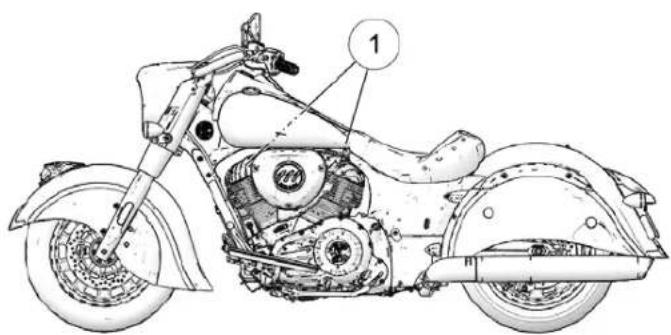
| SPARK PLUG SPECIFICATIONS | |
| Spark Plug Type NGK DCPR8E | |
| Spark Plug Gap .034 inch (.9 mm) | |
| Spark Plug Torque 12 ft-lbs (16.3 Nm) | |
- Make sure the engine has cooled to room temperature.
000 Turn the power switch off.
-
Pull upward on the spark plug boots (not the wires) to re the boots.
-
To prevent debris from entering the spark plug holes, use compressed air to clean the area around the plugs before removing them.
Tool: 12 mm plug socket
CAUTION
Wear eye and face protection when using pressurized air.
- Reinstall the spark plugs or install new plugs.
TORQUE
Spark Plug: 12 ft-lbs (16.3 Nm)
- Reinstall the spark plug boots.
SSIIDDEE CCOOVVEERRSS
Remove the left side cover to access the tool kit, shock air f equipped), fuse box and diagnostic connector.
Remove both side covers to access the seat mounting fasteners and the electrical connections for the saddlebags (if equipped).
- Pull outward at each corner of the side cover to disengage the three darts.
- Remove the side cover from the motorcycle.
- To reinstall the side cover, make sure each rubber grommet is properly positioned. Align each dart with the appropriate grommet and press inward firmly to secure each dart.
TIP
Apply lubricant to the grommet to assist with installation.
MAINTENANCE
SSEEAATT RREEMMOOVVAALL
Remove the seat to access the battery.
- Remove the left side cover to access the tool kit.
- Locate the seat mount brackets under the edge of the d seat. Remove the seat mount ^① from each side of the seat,
- Remove the rear bracket②bolwasher and nylon grommet from the passenger portion of the seat (if equipped).
- Lift the rear of the seat and pull rearward to disengage mounting tab of the seat from the frame mount. Do not seat mount brackets to contact the rear fender.
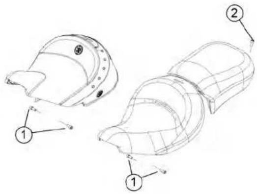
SSEEAATT RREEMMOOVVAALL ((RROOAADDMMAA
- Remove the left side cover to access the tool kit.
- Remove the trunk.
driver's disconnect the trunk harness from the main harness.
- Locate the seat mount brackets under the edge of the drive seat. Remove the seat mount from each side of the seat.
- Remove the rear bracket②boivasher and nylon grommet from front passenger portion of the seat.
- Lift the rear of the seat and unplug the seat heater.
- Pull the seat rearward to disengage the front mounting tab the seat from the frame mount. Do not allow the seat mour brackets to contact the rear fender.
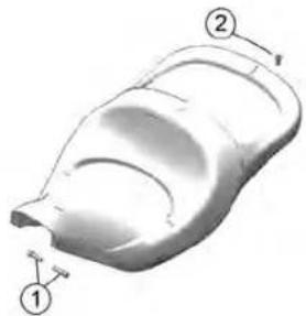
natural_image
3D model of a car body part with labeled parts (1 and 2), no text or symbols present.SSEEAATT IINNSSTTAALLLLAATTIIOONN
- Position the seat by inserting the seat mounting tab from front into the mount on the top of the frame.
- Rotate the rear of the seat downward and position the mount seat brackets onto the frame. Do not allow the mount brackets to contact the rear fender.
- On each side, thread the seat mount bolt through the mount bracket and into the frame. Torque seat bolts to specification.
TORQUE
18 ft-lbs (24 Nm)
- Secure the passenger seat (if equipped). Gently raise the bracket and reinstall the nylon grommet. Thread the rear bracket bolt and washer through the bracket and nylon grommet. Torque the bolt to specification.
TORQUE
96 in-lbs (10.8 Nm)
SSEEAATT IINNSSTTAALLLLAATTIIOONN ((RROO
m. position the seat by inserting the seat mounting tab from front into the mount on the top of the frame.
SideReconnect the seat heater. eat
-
Rotate the rear of the seat downward and position the sill mount seat brackets onto the frame. Do not allow the seat seatmount brackets to contact the rear fender.
-
On each side, thread the seat mount bolt through the seat mount bracket and into the frame. Torque seat bolts to specification.
TORQUE
18 ft-lbs (24 Nm)
- Gently raise the rear bracket and reinstall the nylon gron Thread the rear bracket bolt and washer through the brac and nylon grommet. Torque the bolt to specification.
TORQUE
96 in-lbs (10.8 Nm)
- Reconnect the trunk harness to the main harness.
- Reinstall the trunk.
MAINTENANCE
HHEEAADDLLIIGGHHTT AAIIMM IINNSSPPEECCTMMODNEELLSS EEQQUUIPPPEEDD WWIITTHH LLEE
Adjust headlight aim when there is a change in load (rider, accessories, etc.) or after suspension adjustment.
MMOODDEELLSS EEQQUUIIPPPPEEDD WWIITTHH IINN HHEEAADDLLIIGGHHTTSS
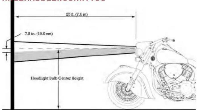
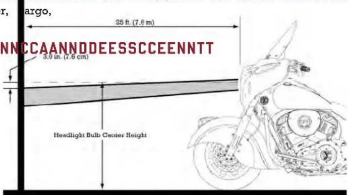
With the headlight switched to LOW beam, the top of the high intensity (appears as a diamond shape) should be 3.0 in (7.6 below the height of the headlight bulb when centered straight ahead at 25 feet (7.62 m).
With the headlight switched to HIGH beam, the center of highest intensity (appears as a diamond shape) should be 7.5 in (19 cm) below the height of the headlight bulb when centered straight ahead at 25 feet (7.62 m).
HHEEAADDLLIIGGHHTT IINNSSPPEECCTTIIOONN PPRROOCCEEDOORREE
Follow all steps below to ensure accurate aim inspection.
- Check and adjust the tire pressure to specification.
- Verify suspension ride height (preload) is set to specification.
- Move the motorcycle to a clear area with a level floor and dim lighting, and place it so the top front edge of the headlight housing is 25 ft. (7.6 m) from the wall.
-
With the rider and passenger (if applicable) on board, bring the motorcycle to a fully upright position. Center the handlebars in a straight ahead position.
-
Start the engine and switch the headlight on to the specified mode:
• INCANDESCENT = HIGH
• LED = LOW
- Compare the position of headlight beam on the wall to illustration below and adjust if necessary.
HEADLIGHT AIM ADJUSTMENT
The headlamp adjustment screwware located inside the headlamp housing.
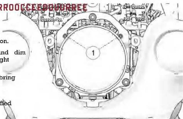
- Remove the two headlight bezel screws (fairing models only) then remove the bezel from the fairing. Reinstall the bezel adjusting the headlamp.
Tool: M4 hex wrench or universal tool
- To adjust the headlamp vertically, tighten both top adjustn screws equally to adjust the beam downward. Loosen both screws equally to adjust the beam upward.
Tool: M4 hex wrench or universal tool
- To adjust the headlamp horizontally, loosen the left side s to adjust the beam to the left. Loosen the right side scre just the beam to the right.
MAINTENANCE
HHEEAADDLLIIGGHHTT LLAAMMPP RREEPPLLAACCEEMMEENNTT top bolts.
NOTICE
For vehicles equipped with LED headlights, the headlight serviceable. If the headlight becomes damaged or inop the entire headlight assembly must be replaced. See authorized INDIAN MOTORCYCLE dealer.
ht is not
36 in-lbs (4 Nm)
erable,
your
- Tighten the four (4) rear bolts.
TORQUE
AAPPPPLLIIEESS TTOO:: CCHHIIEEFF MMOODDEEL
- Remove the six bolts securing the front nacelle headlight shroud. Pull this piece forward to access the headlight.
- Remove the sealing boot. Press the looped end of the wire bulb retainer clip and swing the end toward the center of the bulb to release it from the latch tab.
- With the wire connector attached, pull the bulb out. Disconnect the wire harness.
- Install the new bulb and secure the retainer.
TIP
Avoid touching a halogen lamp with bare fingers. Oil from your skin leaves a residue, causing a hot spot that will shorten the life of the lamp. If a lamp is touched, clean it thoroughly with denatured alcohol.
- Reinstall the sealing boot. Make sure it seals tightly around the bulb base and lens to prevent condensation.
- Reinstall the front nacelle headlight shroud.
HHEEAADDLLIIGGHHTT LLAAMMPP RREEPPLLAACGDEEMMEENNTT((CCHHIIEFF TTAAIINN MMOODDEELLSS))
- Remove the two bolts securing the front trim bezel to fairing. Pull this piece forward to access the headlight.
- Remove the four screw securing the headlamp retaining ring ②. Remove the retaining ring.
Tool: Phillips screwdriver or universal tool
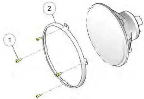
- Remove the headlight assembly from the headlight carrie
the With the wire connector attached, pull the bulb out. Disc the wire harness.
6. Install the new bulb and secure the retainer.
TIP
Avoid touching a halogen lamp with bare fingers. Oil from skin leaves a residue, causing a hot spot that will shorten of the lamp. If a lamp is touched, clean it thoroughly denatured alcohol.
- Reinstall the sealing boot. Make sure it seals tightly around bulb base and lens to prevent condensation.
- Reinstall the headlight assembly into the carrier, being sur index the assembly properly.
- Reinstall the retaining ring with the four screws.
TORQUE
12 in-lbs (1.4 Nm)
- Reinstall the front trim bezel and bolts.
TORQUE
36 in-lbs (4 Nm)
MAINTENANCE
HHEEAADDLLIIGGHHTT LLAAMMPP RREEPPLLA MMAASSTTEERR MMOODDEELLSS))
The LED headlight is not serviceable. If the headlight becor damaged or inoperable, the entire headlight assembly must replaced. See your authorized INDIAN MOTORCYCLE dealer.
LLEEDD TTAAIILLLLIIGGHHTT//BBRRAAKKEE L RREEPPLLAACCEEMMEENNTT
The LED taillight and brake lights are not serviceable. If the taillight or a brake light becomes damaged or inoperable, entire light assembly must be replaced. See your authorized INDIAN MOTORCYCLE dealer or other authorized dealer.
BBAATTTTEERRYY
The motorcycle battery is a sealed, maintenance-free battery. not remove the battery cap strip for any reason. Keep the connections clean and tight at all times.
ACCEEMMEENNTT(IRROOAADD--WARMING
Battery electrolyte is poisonous. It contains sulfuric acid. Serious misses burns can result from contact with skin, eyes or clothing. Antidote:
External: Flush with water.
Internal: Drink large quantities of water or milk. Follow with 1 g of magnesium, beaten egg, or vegetable oil. Call physician immediately.
Eyes: Flush with water for 15 minutes and get prompt medic attention.
Batteries may produce explosive gases.
- Keep sparks, flame, cigarettes, etc. away.
- Ventilate when charging or using in an enclosed space.
• Always shield eyes when working near batteries.
• bHEEPY OUT OF REACH OF CHILDREN.
KKEEYY FFOOBB BBAATTTTEERRYY LLIFFEE::
Key fob battery life is approximately 1-2 years depending on type and usage patterns. Battery changes recommended yearly. Multi-Function (Two Button) Key Fob battery life will decrease v frequent use of the LOCK / UNLOCK buttons.
Low Battery Indicators:
• Decreased fob authentication range
• Horn honks 5 seconds after startup
MAINTENANCE
• Security light stays illuminated for up to 20 seconds
- Both Battery Light and Security Light are illuminated
Key Fob performance can be affected by the following
- Close proximity of ferrous materials (e.g. money clip knife)
• Key Fob stuck to saddlebag speaker magnet
• Key Fob held in ferrous container (metal cup holder or glasses case) - Cold temperatures (Key Fob should be kept above 45^ / 7^ )
or pocket
(1)
[Non-Text]
or glasses
^ F / 7°C)
Key Fob Replacement Battery Part Number: 4014675 or CR2032
BBAATTTTEERRYY RREEMMOOVVAALL
WARNING
Improperly connecting or disconnecting battery cables result in an explosion and cause serious injury or de removing the battery, always disconnect the negative cable first. When reinstalling the battery, always con negative (black) cable last.
conditions:
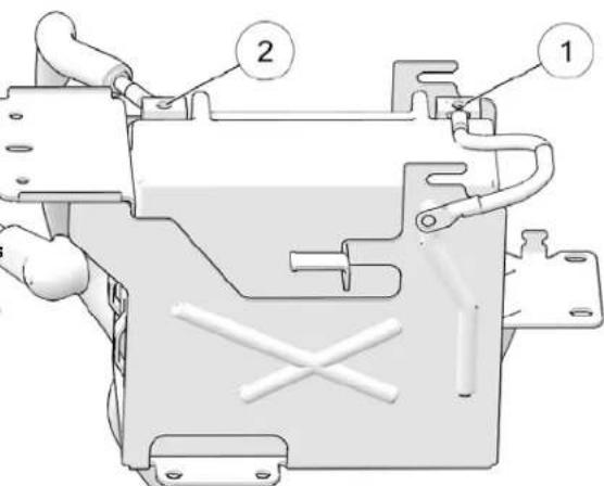
canl. Remove the seat. See page 126 ath. When
_k Remove the negative (-) battery ①cable the battery the terminal. Position the cable well clear of the terminal.
Tool: 10 mm wrench
- Remove the fastener securing the battery cover to the frac crossmember.
MAINTENANCE
- Lift the cover, with the attached Vehicle Control Module in place, folding the wires toward the fuel tank.
Tool: 5 mm hex key wrench
NOTICE
Do not allow the VCM to touch the battery terminals damage the VCM instantly.
- Remove the rubber cover from the positive (+) battery and remove the cable from the terminal. Position the clear of the terminal.
- Remove the battery.
WARNING
If the VCM touches the positive battery post or wire short out.
(VCM)
NOTICE
Do not remove the battery cables while the engine is runnin Doing so may damage the Engine Control Unit (ECU). Take g care not to reverse the battery leads when installing the batt Reverse power applied to the ECU will damage it instantly.
or it will
- Inspect the battery box and cover for damage. Be sure pace in good condition and properly located.
- Make sure cable ends and battery terminals are clean. Applicable film of dielectric grease to the terminal bolt threads.
- Carefully position the battery into the battery box with the negative (-) terminal toward the front of the motorcycle.
the VCM can
BBAATTTTEERRYY IINNSSTTAALLLLAATTIOONN
WARNING
Improperly connecting or disconnecting battery cables can result in an explosion and cause serious injury or death. When removing the battery, always disconnect the negative (black) cable first. When reinstalling the battery, always connect the negative (black) cable last.
- Make sure the positive (+) cableouted horizontally and perpendicular to the long side of the battery. Connect positive (+) cable to the positive (+) battery terminal.
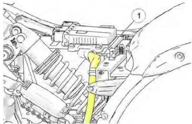
natural_image
Technical line drawing of a mechanical assembly with no visible text or symbolsTORQUE
45 in-lbs (5 Nm)
- Install the negative (-) cable last. Route the starter ground the beneath the frame ground cable on the negative battery terminal.
TORQUE
45 in-lbs (5 Nm)
- Reinstall the battery cover and fastener.
TORQUE
84 in-lbs (9.5 Nm)
- Reinstall the seat. See page 127.
BBAATTTTEERRYY CCHHAARRGGIINNGG
If your motorcycle will not be used for a period of four (4 or longer, a maintenance charger should be connected to the battery using the battery tender plug. The Battery Tender plu located under the left side panel. A maintenance charger can purchased through your authorized INDIAN MOTORCYCLE deals
MAINTENANCE
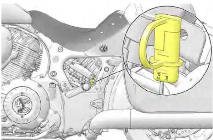
natural_image
Mechanical assembly diagram showing internal components and a highlighted yellow component (no text or symbols)-
Following the charger manufacturer's instructions, use a b charger designed for use with 12-volt batteries. The charge should have a maximum charging rate of 1.8 amps. Cha battery for approximately 10 hours at a rate of 1.8 amp use a taper or trickle charger, it will take longer to ch battery.
-
After charging the battery, allow the battery to sit 1-2 before checking the state of charge with a DC volt met charge should be a minimum of 12.5 DC volts. Repeat charging cycle if the charge is less than 12.5 DC volts. the battery if it fails to reach 12.5 volts after the second
BBAATTTTEERRYY CCHHAARRGGIINNGG AANNDD I
IMPORTANT
Read and follow the safety precautions listed on the battery a the proper battery charging procedures outlined in the Owner Manual.
AGM BATTERY CHARGER RECOMMENDATIONS
Indian Motorcycle recommends using the BatteryMINDER® 2012 AGM - 2 AMP battery charger (PN 2830438) to charge and maintain AGM batteries. The charger can be found on the Indi PG&A website. If not using the BatteryMINDER® 2012 AGM - 2 battery charger, an automatic or constant monitoring AGM battery charger with a charging rate of 2 amps or less is recommend prevent damage to the battery.
Batteries that fall below 12.5V run the risk of sulfation, a conc whereby sulfate crystals form inside the battery and significantly reduce performance. AGM chargers are designed specifically for charging AGM type batteries and use high frequency pulses to partially reverse sulfation.
| Large the | IMPORTANT |
| The use of non-AGM battery chargers may result in a hourBattery not found" or "open cell" fault message. Pleaer. Theyou are using the recommended AGM charger when theAGM type batteries. | |
| Replace | |
AAGGMM BBAATTTTEERRY CCHHAARRGGIINNGG RREECCOMMMEENNDOAATTUOQNSS LLOOWW CCHHAARRGGEE R: Carefully conted the two batteries positive terminals, then negative terminals using jumper cables.
The nominal voltage for an Indian Motorcycle battery is 12. when fully charged. The battery will self-discharge when disconnected from a vehicle, and will discharge at a faster when connected. If the battery voltage falls below 12.5V, it be charged immediately using the recommended battery cha
Batteries which are not connected to a vehicle should be in every 2-3 months. The battery must be charged if found to below 12.5 volts.
Always use the recommended automatic battery charger, and wait for the charger to complete the charge cycle before disconnecting it. 3. After
- Vcnect the recommended battery charger to the low batte and initiate the charging sequence.
rate
should

WARNING
Always check to ensure the positive cables are connected to unspositive terminals before powering the charger on. Reversing polarity when charging can damage electrical components and risk personal injury. Be careful not to let battery cable cl touch each other.
AAGGMM BBAATTTTEERRYY CCHHAARR DEEPLY DISCHARGED (BELOW 3 VOLTS)
AGM batteries discharged to a voltage of 3 volts or less recognized by the recommended automatic battery charger. Minimum voltage threshold recognized by other battery charge may be as high as 10.5 volts). Often times deeply discharged batteries can be restored by attaching another, fully-charged, battery to "jump start" the low battery. Follow the steps to restore a deeply discharged battery.
-
After the charging sequence has initiated, disconnect the fully-charged battery. Always disconnect the fully-charged battery with a low battery negative, low battery negative, and finally fully-charged battery negative
-
Proceed with charging both batteries to full capacity. Listed may not be the table below are the approximate charging times for d ers discharged batteries. Always use the recommended automatic battery charger, and wait for the charger to complete the charge cycle before disconnecting it. The recommended automatic charger will indicate when the battery is fully charged on its display.
AAGGMM BBAATTTTEERRY CCHHAARRGGIINNGG RACEECKOMMAMEENNORRAYTMMOONNOSTEENNAANNCTTAABBLLEE 1. If the motorcycle will not be driven for more than 2 weeks
| STATE OF CHARGE | VOLTAGE (DC) | ACTION | RECOM-MENDED CHARGE TIME* |
| 100% 12.8-13.2 V None | None Required | ||
| 75%-100% 12.6-12.8 V | May need slight charge If no charge given, check again within weeks | 2-4 Hours | |
| 50%-75% 12.3-12.6V | Needs Charge | 4-6 Hours | |
| 25%-50% 12.0-12.3V | Needs Charge | 6-8 Hours | |
| 0%-25% 12.0V or less | Needs Charge | At Least 8 Hours | |
| *Assuming 2 Amps constant current | |||
- If the motorcycle will not be driven for more than 2 weeks maintaining the battery with the Battery Minder 2012-AGM charger (PN 2830438) is recommended.
- To help prolong battery life, it is recommended to remove battery from vehicles stored ONE month or longer. To maximize the life of stored batteries, they should be kept in cool / dry location. Batteries will self discharge more rapidly when stored in extreme temperatures. Batteries should be maintained using the recommended battery charger while in storage.
- Batteries will self-discharge more quickly when dirty. Periodic cleaning of the battery terminals using a terminal brush will help maximize battery life. Wash terminals with a solution of one tablespoon baking soda and one cup water. Rinse well tap water and dry off with clean shop towels. Coat the ten with dielectric grease or petroleum jelly.
- Battery connections should be tightened to the correct torque during installation. This will reduce voltage drop and ensure a reliable connection between the regulator/rectifier and battery.
FUSE REPLACEMENT
| NOTICE |
| Use fuses with the recommended amperage to avoid da the electrical system. |
SSTTAANNDDAARRDD FFUUSSEESS
The standard fuse box is located under the left side cover _2 . fuse box houses all standard service fuses and the automatic circuit breakers. Fuse application and size are provided on a on the fuse box cover.
TIP
Use the fuse puller provided in the tool kit to remove
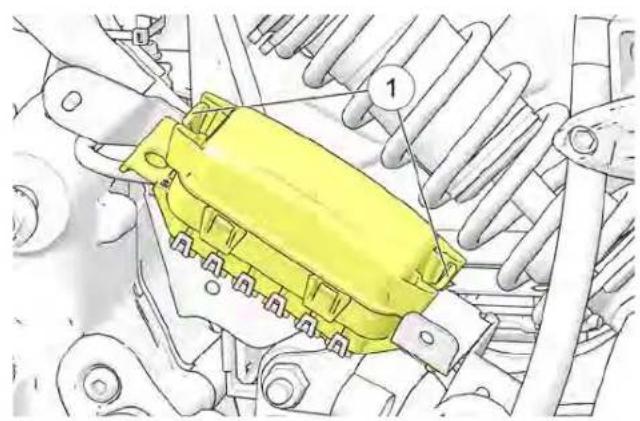
natural_image
Technical diagram of a yellow automotive component with numbered parts, no readable text or symbols present- Remove the left side cover. See page 124.
- This release the locking tabs, squeeze the upper and lower clips.① and remove the fuse box cover.
- After replacing a fuse, reinstall the fuse box cover and s cover.
HHUGGHH--CCUURRRREENNTT FFUUSSEESS
The JCASE® fuse box contains the high-current fuses for the chassis, vehicle control module and anti-lock brake system. The fuse box is located next to the battery box.
Fuse application and size are provided on a label on the fu cover.
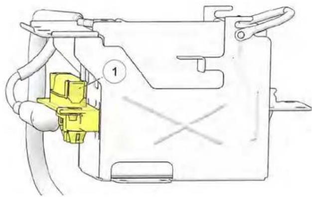
natural_image
Technical line drawing of a mechanical component with yellow connector and labeled part (1), no readable text or symbols present.MAINTENANCE
EELLEECCTTRRIICCAALL PPRREECCAAUUTTIIOQUNMSLOOCCKKIINNGG TTHHEE SSEECCUURRIITT
Be aware of the following precautions regarding the electric hour dealer will provide the master personal identification numb system to avoid disruption of electrical signals and possible (PIN) for the security system. Your dealer may also change the system malfunction. master PIN to a new rider PIN on your behalf.
• DO use ONLY genuine INDIAN MOTORCYCLE parts and Record both PINs on page 7.
accessories designed for your model, and follow the instructions provided. Change the dealer-provided PIN to a PIN of your own choosing soon as possible after receiving delivery of your new motorcycle
• DO use the accessory power jack provided (if equipped). See page 141.
- If it is necessary to provide power to an item that does not use one of the previously mentioned power jacks, connect to the load side of the main circuit breaker and connect the ground wire to the engine ground at the front left side of the following case. If a key fob is not available, your rider PIN can be entered the turn signal switches to unlock the security system. Use the following guide to enter your valid rider PIN.
(near the circuit breaker). On DARK HORSE models the breaker is located under the cover next to the oil filter. On all other models it's located under the cover behind cooler.
• DO NOT splice or cut any wires.
- DO NOT tap in to any power or ground on the motorc specifically directed to do so by the INDIAN MOTORCYC instructions that come with the kit.
• DO NOT back-probe electrical connectors on the vehicle directed to do so by the INDIAN MOTORCYCLE Service Ma.
- DO NOT power any accessories from the diagnostic conn (under left side cover).
| DIGIT TO ENTER adapter.the oilThe number "0" | TURN SIGNAL FEATURE USED | PROCEDURE |
| CANCEL switch | Press and release | |
| First digit (1-9) | LEFT turn switch | Move and release or per digit value. See example below. |
| Second digit (1-9) | RIGHT turn switch | |
| Third digit (1-9) | LEFT turn switch | |
| Fourth digit (1-9) | RIGHT turn switch | |
| Final. | ||
| Example for entering the number 1024: | ||
| EERT-CANCEL-LEFT-LEFT-RIGHT-RIGHT-RIGHT | ||
CCHHAANNGGIINNGG YYOOUURR SSEECCUURRIATTYY SSYYSSTTEEMM PPINN Enter a new A-digit security pin in your own choosing. In To change your PIN, you must have either the key fob or your is successfully entered, the security light and/or power swi existing valid PIN available to gain access to the security system. If remain on and the horn will sound briefly. Proceed t the key fob is not detected or is not available and you cannot
remember your PIN, please see your INDIAN MOTORCYCLE dealer.
Please read the entire procedure before beginning.
- Turn the power switch on. Do NOT start the engine. security light and/or power switch will turn on briefly key fob is detected or until the valid, current PIN is
- Push or hold the turn signal CANCEL switch for 10 until the security light and/or power switch turn on.
NOTICE
On models with Infotainment Display, a pop-up window appear during this procedure stating that the key fob is range.
3. Enter either the master PIN (see page 7) or your current rider PIN within 20 seconds. If the PIN is successfully exiting the security light and/or power switch will remain on an horn will sound briefly.
NOTICE
If the valid PIN is not entered within 20 seconds, the and/or power switch will flash for 10 seconds, then t will shut down. Return to step 1 to try again
The then the system exits the procedure. Return to step 1 to it
until the
enter Re-enter the new 4-digit PIN. If this entry matches the fir
the security light and/or power switch will turn off and th
econd will sound briefly. The new rider PIN has been saved. Re
your new rider PIN on page 7.
NOTICE
If the 4-digit PIN is NOT successfully entered within 20 sec, the security light and/or power switch will flash for 10 sec then the system exits the procedure. Return to step 1 to tr
will is out of the second entry is not entered within 20 seconds or d match the first entry, the security light and/or power switch flash for 10 seconds, then the system exits the procedure. new PIN was NOT saved. Continue to use your former vali rent 4-digit Return to step 1 to try again.
NOTICE
EENNGGIINNEE CCOOMMPPRREESSSSIIOONN TT
An engine compression test can be performed to monitor general engine condition. See the INDIAN MOTORCYCLE Service Manual of security-authorized INDIAN MOTORCYCLE dealer can assist. e system
MAINTENANCE
EEXXHHAAUUSSTT SSYYSSTTEEMM IINNSSPPEECAGSSTODENNEERR IINNSSPPEECCTTIOONN
Check the exhaust system for stains from leaking exhaust gasses. Replace damaged or leaking exhaust gaskets. Check all exhaust system fasteners. Tighten loose clamps and fasteners. Do not overtighten. See the INDIAN MOTORCYCLE Service Manual or an authorized INDIAN MOTORCYCLE dealer can assist.
- Always replace stripped, damaged or broken fasteners before fixing Use Genuine INDIAN MOTORCYCLE fasteners of equal size and strength.
EELLEEVVAATTIINNGG TTHHEE MMOOTTOOR
WARNING
Serious injury or death can occur if the motorcycle Make sure the motorcycle will not tip or fall while while on the sidestand.
FFAASSTTEENNEERR TTOORRQQUUEESS
Some procedures and fastener torques are not listed in this manual. See the INDIAN MOTORCYCLE Service Manual or an authorized INDIAN MOTORCYCLE dealer can assist.
Some procedures require raising the motorcycle to remove weight from the component being inspected. Elevate the motorcycle by placing a stable, flat platform jack or lift mechanism on a firm, flat surface and lifting under the engine crankcase. The platform should be a minimum of 12 in (30 cm) square. DO NOT attempt to lift the motorcycle without proper equipment. Always secure the motorcycle properly before lifting so it cannot tip or fall when elevated.
RROOAADD TTEESSTT
Before returning the motorcycle to regular use, perform a road test in a safe area. Pay special attention to the proper fit and operation of all serviced components.
Make any corrections or additional adjustments promptly to ensure safe, reliable and enjoyable vehicle performance.
TTRROOUUBBLLEESSHHOOOOTTIINNGG
For your personal safety, do not attempt inspection or repairs not fully described in this rider's manual. Contact an authorized dealer for service if you cannot determine the cause of a problem or if the inspection/repair exceeds your mechanical ability or tool resources. Do not perform any inspection or repair with the engine running.
EENNGGIINNEE CCRRAANNKKSS BBUUTT WWIILLLN NNOOTT SSTTAARRTT
| POSSIBLE CAUSE POSSIBLE REMEDY/ACTION | |
| Low Fuel | Verify fuel level. |
| Fuel Pump Inoperative | Turn engine STOP switch to RUN. Turn the power switch on. The fuel pump should run momentarily and then stop. Check the fuel pump/ignition circuit breaker. |
| Battery Voltage Too Low | Fully charge the battery. |
| Spark Plug(s) Fouled | Inspect spark plugs. |
| Spark Plug Wire(s) Disconnected or Loose | Be sure spark plug wires are securely fastened. |
| Low Compression | Please see your dealer for an engine compression test. |
STARTER MOTOR CLICKS, DOES NOT TURN OR TURNS SLOWLY
| POSSIBLE CAUSE POSSIBLE REMEDY/ACTION | |
| Engine Stop/Run Switch in Stop Position | Place switch in RUN position. |
| Battery Discharged | Fully charge the battery. |
| Battery Cables Loose or Corroded | Inspect battery cables. |
| Transmission In Gear | Shift transmission into neutral or pull the clutch lever in to disengage the clutch. |
| Key Fob Not Authenticated | Make sure key fob is within range and that key fob battery voltage is not low. |
| Sidestand is Down With Transmission in Gear | Shift to neutral or retract the sidestand fully. |
MAINTENANCE
EENNGGIINNEE SSTTAARRTTSS BBUUTT MMIISSSSEESS OORR RRUUNNSS PPOOOORRLLYY
| NOTICE |
| Turn engine OFF before inspecting any of these items. |
| POSSIBLE CAUSE POSSIBLE REMEDY/ACTION | |
| Battery Discharged Fully charge the battery. | |
| Battery Cables Loose or Corroded | Inspect battery cables and connections. |
| Spark Plug(s) Fouled | Inspect spark plugs. |
| Spark Plug Wire(s) Loose or Wet | Inspect spark plug wires, ensure dry/secure. |
| Contaminated Fuel | Inspect fuel for water-contamination. Please see your dealer. |
| Engine Oil Level Incorrect Or Wrong Type | Inspect level and quality of oil. |
| Loose, Broken, Shorted Ignition Coil Wires | Inspect coil primary wires. Please see your dealer. |
| Air Intake Restricted | Inspect air filter. |
| Intake Leaks | Inspect air box, throttle body and intake boot joints. |
SSHHIFFTTIINNGG DDIIFFFFIICCUULLTTIIEESS OORR HHAARRDD TTOO FFIINNDD NNEEUUTTRRAALL
| POSSIBLE CAUSE | POSSIBLE REMEDY/ACTION |
| Shift Linkage Bushings Dry Or Worn | Lubricate shift linkage. |
| Clutch Damage | Replace clutch. |
| Clutch Cable Not Adjusted Properly | Please see your dealer for inspection and adjustment. |
| Shift Linkage Not Adjusted Properly | Please see your dealer for inspection and adjustment. |
MAINTENANCE
BBAATTTTEERRYY CCHHAARRGGIINNGG RRAATTEE LLOOWW OORR BBAATTTTEERRYY DDISSCCHHAARRI
| POSSIBLE CAUSE POSSIBLE REMEDY/ACTION | |
| Loose/Corroded Charging Circuit Connection | Check/clean battery cable connections. Check/clean charging circuit connections. Please see your dealer. |
| Accessory Load Exceeds Charge Rate Limit accessory operation when the engine is off. | |
| Improperly Wired Accessory (Current Draw) Please see your dealer to check charging system output and current draw. | |
BRAKE NOISE/POOR BRAKE PERFORMANCE
| NOTICE |
| See your dealer if brake performance does not return after these inspections. |
| POSSIBLE CAUSE POSSIBLE REMEDY/ACTION | |
| Dust/Dirt On Brake Disc(s) | Clean disc. |
| Worn Pads Or Disc/Brake Disc Damage | Inspect pads. |
| Brake Fluid Level Low Or Fluid Contaminated | Inspect fluid level/fluid condition. |
ANTI-LOCK BRAKE LIGHT REMAINS ILLUMINATED OR ILLUMINATES INTERMITTENTLY
| POSSIBLE CAUSE POSSIBLE REMEDY/ACTION | |
| Blown fuse | Check the fuses. See page 138. |
| Loose or damaged pulse ring | Inspect pulse ring for looseness or chipped teeth. |
| Debris lodged in components | Inspect wheel speed sensor and pulse ring for debris. |
MAINTENANCE
| POSSIBLE CAUSE POSSIBLE REMEDY/ACTION | |
| Damage caused by debris Inspect wheel speed | sensor for cracked housing. |
| Damaged components See service manual or authorized dealer. | |
CCLLEEAANNIINNGG AANNDD SSTTOORRAAGGEE
CCLLEEAANNIINNGG PPRROODDUUCCTTSS
This section provides tips on the very best way to clean, preserve every surface of your beautiful new INDIAN MOTORCYCLE. We recommend the use of our new INDIAN MOTORCYCLE cleaning and polishing products and accessories which have been specially designed to offer the best care for your INDIAN MOTORCYCLE.
In addition to the products recommended in this section for cleaning and polishing, INDIAN MOTORCYCLE also has speci products for:
• enhancing black and silver engines
- cleaning engines, tires and wheels
- removing brake dust
After cleaning the motorcycle, inspect for damage to the surfaces. Chips or scratches should be repaired promptly prevent corrosion.
For Matte Clear Coat Finish Care, see the Matte Clear Coat Care section for details.
For Gloss Clear Coat Finish Care, see the Gloss Clear Coat Care section for details.
For more information, or for answers to your cleaning and questions, please see your INDIAN MOTORCYCLE dealer or https://www.indianmotorcycle.com/en-us/self-help/article/KA-01210/.
WWAASSHHIINNGG TTHHEE MMOOTTOORRCCYYCC
| polish andNOTICE |
| Do not use pressurized water to wash the motorcycle. Water, seep in and deteriorate wheel bearings, brake caliper possisiermlies, brake master cylinders, electrical connectors, steering head bearings, and transmission seals.Do not direct any water stream at air intakes, exhaust our electrical connectors or audio system speakers.Electrical components may be damaged by water. Do not a water to contact electrical components or connectors. |
- Before washing, make sure exhaust pipes are cool. Cover pipe opening with a plastic bag secured with a strong ru band. Check that the spark plugs, spark plug wire caps,
ainted and fuel caps are properly seated. -
Do not use abrasive cleaners.
-
Rinse off as much dirt and mud as possible with water at low pressure. Use as little water as possible when was near the air intake or the exhaust pipe openings. Dry the Finish components thoroughly before using the motorcycle.
-
Clean the front fork tubes thoroughly to reduce fork seal detailing leakage.
CLEANING AND STORAGE
- After washing, remove the rubber bands and plastic bag the exhaust pipes. Start the engine and let it idle for a minutes.
- Make sure the brakes are functioning properly before rid
WWIINNDDSSHHIIEELLDD CCAARREE ([IFF EEO
Clean the windshield with a soft cloth and plenty of warm Dry with a soft clean cloth. Remove minor scratches with a high-quality polishing compound designed for use on polycarbonate surfaces.
NOTICE
Brake fluid and alcohol will permanently damage the wind. Do not use glass cleaners, water or soil repellents, and or alcohol based cleaners on the windshield, as these can damage the windshield.
MATTE CLEAR COAT FINISH CARE
Matte finish products are prone to trapping dirt, oils and others do not use pressurized water to wash the motorcycle. When contaminants. Always clean this type of finish with warm water paint is still fresh, pressurized water could damage the finish a mild dish-washing detergent. Use a soft sponge to gently rubbing a pressure washer is unavoidable, keep the spray nozz surface, then rinse with clean warm water. For stubborn stains at least 24 inches (60 cm) away from the surface of the as grease or oil, use a citrus-based cleaner. Spray the clean motorcycle.
the area and rub gently with a soft sponge. Allow the clean wash your motorcycle often, especially when exposed to salty for a couple of minutes, then rinse well with clean warm watery, acidic or alkaline environments.
Repeat as needed.
| s from | IMPORTANT |
| few | |
| Never use a polishing/buffing wax or any sponge that has a abrasive surface when cleaning a matte finish. These products dingwill buff the matte surface of the finish and result in a gl finish. Never clean matte finishes with a pressure washer, as (QUWIIIPPPPEEED) water. contaminants into the clear coat and may damage labels and decals. | |
GLOSS CLEAR COAT FINISH CARE
The clear coat finish system used on all INDIAN MOTORCYCLE provides superior protection against the elements. To maximize the benefits of this system, use the following guide to care for endsbest finish on your motorcycle.
petroleum producing the first 30 days, when the finish is still fresh, clean motorcycle with a water rinse only.
- Do not wax the motorcycle for the first 60 days. Doing so cause loss of the gloss. After 60 days, use only waxes design for new clear coat finishes.
- Use warm or cool water and a soft cloth for cleaning.
- Use soaps that are non-abrasive and have a neutral pH (non acidic/non alkaline detergents).
- Do not use solvent-based solutions.
- Do not use a dry cloth to remove dust.
- Do not use a stiff bristle brush, which can scratch the
- Do not wash with extremely hot water.
- Do not wash the motorcycle while the surface is hot a washing the motorcycle in the hot sun. Minerals in the may be difficult to remove once dried on the surface motorcycle.
- Do not allow spilled gasoline, motor oil or brake fluid on the paint. Remove these substances immediately by with water. Use a soft cloth to absorb any remaining dab dry.
- To remove bug remnants or road tar, use only products specifically designed for this purpose. Follow the product manufacturer's recommendations to prevent potential damage to the finish. Follow with a wash using the methods des this section.
• Always brush away any ice or snow, do not scrape off. - Chips or scratches should be repaired promptly to prevent corrosion.
LLEEAATTHHEERR CCAARREE LLEEAATTHHEERR FFAACCTTSS
Surface. Leather is a natural product and will exhibit qualities inherent in natural material. Fading, wrinkles, grain changes, creases and smartpin marks are assurance that this material is not man-made water product is used, each leather product will exhibit tarnish fuses the Regular care will help keep premium leather products like their best.
EEXXPPOOSSUURREE TOO SSUUNN
There are many environmental elements that will contribute to aging of leather products. Regular exposure to the sun, along with from the sun and exhaust system or engine components, rapidly fade the leather. Heat from the sun will dry the leaf potentially causing it to crack. Periodic application of the INE MOTORCYCLE Leather Care Dressing Kit will replace the oils, maintaining the leather's natural surface. Periodic use of the Leather Care Dressing Kit will help restore and maintain the oil-tanned color and finish to help keep it looking its best.
EEXXPP00SSUURREE TOO MMOOISSTUURREE
IINNFFOOTTAAIINNMMEENNTT TTOOUUCCHHSS
We recommend using a gentle detergent and water to clear touchscreen. Wash and dry with a lint free cloth.
- Do not expose to brake fluid.
- Do not expose to gasoline.
- Do not expose to DEET.
If leather is exposed to moisture, wipe down the leather pro and allow them to dry naturally at room temperature. Do no attempt to accelerate the drying process by using heat. Heat the leather will remove the natural oils and cause it to dry crack. Whenever possible, take steps to protect the leather for exposure to moisture.
CLEANING AND STORAGE
NOTICE
The leather used on INDIAN motorcycles is an all-m product; exposure to moisture will result in structural of the material, causing permanent damage. Regular usage INDIAN MOTORCYCLE Leather Care Dressing will help this type of damage.
EEXXPP00SSUURREE TTOO DDIIRRTT//DDUUSSTT
Leather items on motorcycles can get extremely dirty with use. It is acceptable to wipe down leather products with a and clean water, especially after a long ride. If extremely a small amount of mild soap in the water and follow with water rinse.
LLEEAATTHHEERR CCAARREE DDRREESSSSIINNGG
INDIAN MOTORCYCLE Leather Care Dressing is a leather conditioner formulated to restore many of the oils that are leather due to exposure to environmental elements. This conditioner is suitable for all oil-tanned leather on your IN motorcycle, but it should never be used on suede.
This leather care dressing will also restore some of the co through natural aging and now includes UV protection. The aging depends on how often the motorcycle is used, how stored, and weather conditions. While visible signs of aging more noticeable on natural leather, lack of care may cause non-warrantable damage to both natural and black leather.
LLEEAATTHHEERR CCAARREE DDRREESSSSIINNGG AAPPI
Apply Leather Care Dressing as part of a regular maintenance regime, such as polishing chrome and washing painted surfaces. Apply this treatment at least one time per month. Apply more if the motorcycle is regularly exposed to the elements or park the sun.
- Wipe down leather with a sponge and clean water.
- Wipe down leather with a dry towel and allow it dry at no normal temperature. Do not use heat to accelerate drying time.
sponge 3 With use a clean cloth, lightly rub the dressing into the leather dirty wine off any excess. Be cautious not to allow droplets or g a clean of the treatment to sit on an area of the leather as that a darken. For better results, use a straight wiping motion rather than a tight swirling motion. Lighter areas may need more treatment applied to darken them.
4osAllfrom the treatment to dry before riding (typically one hour)
FERRREEQQUUEENNTTLLYY AASSKKEEDD QQUUEESST
QQ.. CCAANN II UUSSEE SSHHOOEE PPOOLLISSHH TTOO COOLLOORR??
A. Shoe polish should not be used on the leather items on y: INDIAN motorcycle. Shoe polish contains a dye that can damage the leather and may leave residue on clothing.
QQ.. WWHHAATT SSHHOOUULLDD II UUSSEE TTOO TTRREEANRDOWWHNABINNYAAGCKRPPLLIICCAATTIIODNSS LLEEAATTHHEERR TTHHAATT CCAAMMEE DONN MMYY TINNONIADBBAMNUBBEERRRROPEYSSTLOERREE KKIITT?
A. INDIAN MOTORCYCLE Leather Care Dressing is suitable for Eatch kit contains enough product for two applications. oil-tanned leather on your INDIAN motorcycle. Black leather uses a
different tanning process and may not require application of SGTTOORRAAGGEE AARREEAA PPRREEPPAARRA
QQ.. WWHHAATT SSHHOOUULLDD II UUSSEE OONN MM AACCCCEESSSSOORRIIEESS??
A. INDIAN MOTORCYCLE Leather Care Dressing is suitable oil-tanned leather on your INDIAN motorcycle, including accessories.
If you will not operate the motorcycle for more than 60 days, the motorcycle to prevent damage to the fuel system and the battery and to protect components from corrosion or deteriorating during storage preparation you might use products that are potentially hazardous; such as fuel stabilizer. When using any these products, follow the instructions and warnings on the product packaging.
QQ.. WWHHEERREE CCAANN II PPUURRCCHHAASSEE AAT PAANN DLE FAATTNHEERORREE location, inside a garage other structure if possible. The location should have a firm, surface and allow enough space for the motorcycle.
CCAARREE DDRREESSSSIINNGG??
A. Please see your authorized INDIAN MOTORCYCLE dealer these products and for all of your motorcycle care needs.

QQ.. CCAANN II UUSSEE TTHHEE LLEEAATTHHEERR CCAARREEDDORREESSSIIINGGAAFFETEERR UUSSIINNGG TTHHEE TTAANN LLEEAATTHHEERR RREESSTORREEKKIITT??be near open flames, pilot lights, s
A. Yes. The leather care dressing should be applied at least once or electric motors. Do not per month (more often in extreme conditions) to maintain the desired finish. Apply leather care dressing as part of a regular best preserve tire condition: exterior maintenance plan (e.g. polishing chrome and washing painted surfaces).
CLEANING AND STORAGE
- The storage area should have a relatively constant and temperature.
- The storage surface should be free of oil and gasoline.
- The motorcycle should not be near a radiator or other source, or any type of electric motor.
CCLLEEAANN AANNDD PPRROOTTEECCTT TTH
To prepare the motorcycle for storage, begin by cleaning and polishing the motorcycle as outlined beginning on page 149.4 Polish chromed and other metal surfaces. Apply protectant to exposed rubber, vinyl and plastic parts. Do not apply rubber protectant to the tire tread surfaces.
FFUUEELL SSTTAABBIILLIIZZEERR
Add fresh fuel to fill the fuel tank and add fuel stabilizer. overfill.
Ride the motorcycle or start and run the engine for 15 m well ventilated area to distribute the stabilizer throughout the system.
TTIIRREE IINNFFLLAATTII0ONN
Inflate the tires to normal pressure. See page 122.
EENNGGIINNEE PPRROOTTEECCTTII0ONN
Change the engine oil.
BBAATTTTEERRYY CCAARREE
- Remove the battery. See page .
Heat Clean the battery terminals first with a wire brush to remove any loose deposits. - Wash the posts and the ends of the battery cables with a rolling one, having good to 16 parts water. Rinse v and clean water and wipe dry.
- Apply a thin film of dielectric grease to the posts and cab: o connectors.
- Clean the outside of the battery with a solution of mild detergent and warm water.
- Store the battery in a dry area with a temperature of 32^ D_6(0^ and 32^ C).
- While in storage, fully charge the battery once a month. Se
MMAAIINNTTEENNAANNCCCEE DDUURRIINNGG SST1
During extended storage periods, maintain tire pressure and battery voltage at the recommended levels.
RROODDEENNTTSS
Mice and other rodents are often the worst enemy of a stored motorcycle. If the motorcycle will be stored in an area where mice are a concern (particularly in rural areas, barns, sheds, etc.) be sure to take extra measures to deter their infestation. This may include placing a screen mesh over any intake or exhaust openings (remember to remove them when you remove the motorcycle from storage).
PPAARRKK AANNDD CCOOVVEERR TTHHEE MMOOREHORROCVXACCLIFFERROOMM SSTTOORRAAGGEI
- Park the motorcycle in its storage location. Block the frame install a fully charged battery. take some of the weight off the front and rear wheels. 2. Check the oil level. If the m
NOTICE
Starting the motorcycle periodically during storage is recommended. Water vapor is a by-product of the co process, and corrosion may result unless the engine is long enough to bring the oil and exhaust system to operating temperature.
NOT
tion
NOTICE
operated
During storage, temperature and humidity changes can normal condensation to form in the crankcase and mix with Running the engine with oil that contains condensation engine damage.
cause engine can cau
-
Secure a plastic bag over the (cooled) exhaust outlets prevent moisture from entering the exhaust system.
-
Cover the motorcycle with a cover made from a durable breathable material designed for storage. Covering the motorcycle helps protect it from dust and other airborne materials. The cover must be of a breathable material to prevent moisture from building up on the motorcycle which cause oxidation of metal surfaces.
-
Inspect the storage area for signs of fluid leaks. Identify an e, perform service to any leaking components.
- Remove any intake or exhaust mesh covers installed for rod protection.
ish install new spark plugs if necessary.
-
Perform the pre-ride inspections outlined in this manual.
-
Perform a road test. See page 142.
-
Wash and polish the motorcycle. Wax, polish or apply protectant to appropriate components.
SSPPEECCIFFIICCAATTIIOONNSS
DDIIMMEENNSSII00NNSS
Dimensions and specifications may vary with features, options and accessories.
| CHIEF SPRINGFIELD / SPRINGFIELD DARK HORSE | CHIEFTAIN / CHIEFTAIN DARK HORSE | CHIEFTAIN LIMITED ROADMASTER | |||
| Overall Length 103.5 in. | (2630 mm) Dark Horse103.7 in. (2634 mm) Vintage | 101.7 in. (2583 mm)99.1 in. (2634 mm) Dark Horse | 101.2 in. (2571 mm) | 98.7 in. (2506 mm) | 104.6 in. (2656 mm) |
| Overall Width | 39.4 in. (1000 mm) | 39 in. (990 mm) | 39.4 in. (1000 mm) | 39.4 in. (1000 mm) | 39.4 in. (1000 mm) |
| Overall Height | 46.3 in. (1176 mm) Dark Horse58.7 in. (1491 mm) Vintage | 56.8 in. (1442 mm) | 54.6 in. (1388 mm) | Limited: 54.6 in. (1388 mm) | 58.7 in. (1491 mm) |
| Seat Height | 26 in. (660 mm) | 26 in. (660 mm) | 26 in. (660 mm) | 26 in. (660 mm) | 26.5 in. (673 mm) |
| Wheelbase | 68.1 in. (1730 mm) | 67 in (1701 mm) | 65.7 in. (1668 mm) | 65.7 in. (1668 mm) | 65.7 in. (1668 mm) |
| Ground Clearance | 5.5 in. (140 mm) | 5.6 in. (142 mm) | 5.6 in. (142 mm) | 5.6 in. (142 mm) | 5.5 in. (140 mm) |
| Rake (frame)/Trail | 29°/6.1 in. (155 mm) | 25°/5.2 in. (133 mm) | 25°/5.9 in. (150 mm) | 25°/5.9 in. (150 mm) | 25°/5.9 in. (150 mm) |
WEEIIGGHHT
| CHIEF SPRINGFIELD / SPRINGFIELD DARK HORSE | CHIEFTAIN / CHIEFTAIN DARK HORSE | CHIEFTAIN LIMITED | ROADMASTER | |
| Dry Weight (without fuel/fluids) | Dark Horse: 745 lbs. (338 kg) Vintage: 818 lbs. (371 kg) | Chieftain: 783 lbs. (355 kg) Chieftain Dark Horse: 802 lbs. (364 kg) | Limited: 817 lbs. (371 kg) | 912 lbs. (414 kg) |
| Wet Weight (with fuel/fluids) | Dark Horse: 777 lbs. (352 kg) Vintage: 850 lbs. (385 kg) | Chieftain: 815 lbs. (370 kg) Chieftain Dark Horse 834 lbs. (378 kg) | Limited: 834 lbs (378 kg) | 944 lbs. (428 kg) |
SPECIFICATIONS
| CHIEF SPRINGFIELD /SPRINGFIELD DARKHORSE | CHIEFTAIN / CHIEFTAINDARK HORSE | CHIEFTAIN LIMITED ROADMASTER | |||||||
| Gross Vehicle Weight Rating (GVWR) | 1260 lbs. (573 kg) 1385 | lbs. (628 kg) 1385 lbs. | (628 kg) 1385 lbs (628 kg) | 1385 lbs. (630 kg) | |||||
| Gross Axle Weight Rating (GAWR) | Front 485 lbs. (220 kg)Rear 775 lbs. (352 kg) | Front 500 lbs. (227 kg)Rear 885 lbs. (401 kg) | Front 500 lbs. (227 kg)Rear 885 lbs. (401 kg) | Front 500 lbs (227 kg)Rear 885 lbs (401 kg) | |||||
| Maximum Load Capacity (riders, cargo, accessories) | Dark Horse: 483 lbs. (215 kg)Vintage: 410 lbs. (186 kg) | $23 lbs. (237 kg) Chieftain: 570 lbs. (258 kg)Chieftain Dark Horse: 551 lbs. (250 kg) | Limited: 551 lbs (250 kg) | ||||||
CCAAPPAACCIITTIIEESS
| CHIEF MODELS SPRINGFIELD MODELS / CHIEFTAIN MODELS / ROADMASTER MODELS | ||
| Engine Oil | 5.5 qts. (5.2 l) with filter at oil change | 5.5 qts. (5.2 l) with filter at oil change |
| Fuel | 5.5 gal. (20.8 l) | 5.5 gal. (20.8 l) |
| Fuel Reserve (fuel light on) 1.0 gal. | (3.8 l) | 1.0 gal. (3.8 l) |
| Fork Oil | 20.3 oz. (599 cc) | 18.8 oz. (557 cc) |
EENNGGIINNEE
| ALL MODELS | |
| Engine Type | ThunderStroke 111, Air Cooled |
| Configuration | V-Twin |
| Displacement | 111 cu. in. (1811 cc) |
| Cooling System | Air Cooled (CHIEF, SPRINGFIELD)Air/Oil Cooler (CHIEFTAIN DARK HORSE) |
| Compression Ratio | 9.5:1 |
| Valve Train | 2 Valves Per Cylinder, Hydraulic Lifters |
| Bore and Stroke | 3.976" x 4.449" (101mm x 113mm) |
| Fuel System/Throttle Body Bore | Closed Loop Fuel Injection/54 mm |
| Exhaust System | 1 into 2 with Catalytic ConverterSplit Dual Exhaust with Cross-over |
SPECIFICATIONS
| ALL MODELS | |
| Rev Limit 5400 RPM | |
| Idle RPM 800 +/- 50 RPM Fully Warm | |
| Lubrication System Semi-Dry Sump | |
| Spark Plug/Gap NGK DCPR8E/.034 inch (0.90 mm) | |
DDRRIIVVEE SSYYSSTTEEMM
| ALL MODELS | |
| Primary Drive Gear Drive Wet Clutch | |
| Crank Gear 55 Teeth | |
| Clutch Gear 86 Teeth | |
| Clutch Type | Wet, Multi-Plate. Assist |
| Primary Reduction Ratio | 1.564:1 |
| Transmission Type | 6 Speed/Constant Mesh/Foot Shift |
| 1st Gear Ratio | 2.733:1 |
| 2nd Gear Ratio | 1.864:1 |
| 3rd Gear Ratio | 1.385:1 |
| 4th Gear Ratio | 1.103:1 |
| 5th Gear Ratio | 0.943:1 |
| 6th Gear Ratio | 0.811:1 |
| Gear Shift Pattern | 1 Down/5 Up |
| Final Drive Type | Belt Drive, 152-Tooth |
| Transmission | 30-Tooth |
| Rear Wheel 66-Tooth | |
| Ratio | 2.2:1 |
| Overall Gear Ratio | |
| 1st Gear | 9.403:1 |
| 2nd Gear | 6.411:1 |
SPECIFICATIONS
| ALL MODELS | |
| 3rd Gear 4.763:1 | |
| 4th Gear 3.796:1 | |
| 5th Gear 3.243:1 | |
| 6th Gear 2.789:1 |
CCHHAASSSSISS
| CHIEF MODELS SPRINGFIELD MODELS CHIEFTAIN MODELS / | ROADMASTER MODELS | ||
| Front Suspension Type/Travel Telescopic Fork/4.7 in. (119 mm) | |||
| Front Fork Tube Diameter 46 mm | |||
| Rear Suspension Type/Travel Single Shock/3.7 in. (94mm) Single Shock w/ | Air Adjust/4.5 in. (114mm) | ||
| Swing-arm Cast Aluminum | |||
| Front Brakes Dual/4 Piston Caliper/Floating Rotor | |||
| Rear Brakes | Single/2 Piston Caliper/Floating Rotor | ||
WHEELS AND TIRES
| CHIEF MODELS | SPRINGFIELD MODELS | CHIEFTAIN MODELS | ROADMASTER MODELS | |
| Front Wheel Size/Type | 3.5 in. x 16 in. Cast Aluminum3.5 in. x 16 in. Spoked (Vintage) (Dark Horse)3.5 in. x 16 in. Cast Aluminum | Aluminum. x 19 in. Cast Aluminum3.5 in. x 19 in. Cast Aluminum | 3.5 in. x 16 in. Cast Aluminum | 3.5 in. x 16 in. Cast Aluminum |
| Rear Wheel Size/Type | 5 in. x 16 in. Cast Aluminum5 in. x 16 in. Spoked (Vintage) | Aluminum. x 16 in. Cast Aluminum | 5 in. x 16 in. Cast Aluminum | 5 in. x 16 in. Cast Aluminum |
| Front Tire Type/Size | 130/90-B16 73H Dunlop Elite130/90-B16 67H American Elite (Vintage) | Elite 60/60B19 61H Dunlop American Elite (Dark Horse)130/90-B16 73H Dunlop Elite | 130/60B19 61H Dunlop American Elite3 | 130/90-B16 73H Dunlop Elite |
| Rear Tire Type/Size | 180/65B16 81H Dunlop American Elite | 180/60R16 80H Dunlop Elite 3 Multi-Compound | ||
EELLEECCTTRRIICCAALL
| ALL MODELS | |
| Alternator 710W @ 2000 RPM | 610W @2000 RPM (Chief/Chief Dark Horse) |
| Battery 12 Volt, 18 amp/hour, 310 | CCA, Sealed Glass Mat |
| Power Points Front - 10 amp maximum | Rear - 10 amp maximum(Combined - 10 amp maximum) |
| Voltage Regulator 14.4 volts/42 amp | |
| Headlight H4 12V 60/55W LL | Roadmaster: Non-Serviceable LED |
| Auxiliary Light Chief Vintage/Springfield/Chief Dark Horse/Chieftain/Chieftain Limited: H8 35WRoadmaster: Non-Serviceable LED | |
| Tail/Brake Light Non-Serviceable LED | |
| Turn Signal Non-Serviceable LED | |
| License Plate Non-Serviceable LED | |
| Front Fender Light | Non-Serviceable LED |
| Speedometer | Non-Serviceable LED |
| Indicator Lights | Non-Serviceable LED |
SPECIFICATIONS
FFUUEELL RREECCOOMMMMEEENNDDAATTIIIONENNGGIINNEE OOIII L RREECCOOMMMMEEENNDDA
For best performance, use only unleaded gasoline with a 9 Wp recommend the use of INDIAN MOTORCYCLE Premium octane minimum (R+M/2 Method) or 95 RON minimum. DO Synthetic Blend 20W-40 Engine Oil for your motorcycle. This oil USE E-85 GASOLINE OR GASOLINE CONTAINING METHANOL formulated with synthetic-based oil and premium engine additive Using E85 or gasoline/methanol blends can result in poor staffing have physical properties that meet API SM and ILSAC G and driveability, engine damage and damage to critical fuel specifications.
system components.
• Gasoline containing up to 10% Ethanol can be used.
In the event that the recommended premium unleaded gas not available and low octane fuel must be used, fill the only partially with unleaded regular gasoline, then fill the fully with premium unleaded gasoline as soon as possible.


Do not blend oil additives with engine oil.
If oil must be added in an emergency and the recommended not available, choose only a high-quality 20W-40 motorcycle oil. Line is Change back to the recommended oil at the first opportunity. Fuel tank

NOTICE
Use of non-recommended lubricants can result in engine damage. Damage resulting from the use of non-recommended lubricants is not covered by warranty.
FFOORRKK 0011LL
We recommend the use of INDIAN MOTORCYCLE Fork Oil for motorcycle.
BBRRAAKKEE FFLLUUIIDD
We recommend the use of INDIAN MOTORCYCLE DOT 4 Brake Fluid for both brake master cylinders. DO NOT use DOT 5 silicon fluid.
WWAARRRRAANNTTYY
IINNDDIIAANN MMOOTTOORRCCYYCCLLEE WWAARRRRAANNTTYY PPOOLLIICCYY
LLIIMMIITTEEDD WWAARRRRAANNTTYY
INDIAN MOTORCYCLE, 2100 Highway 55, Medina, MN 55340 (INDIAN MOTORCYCLE) gives a TWO YEAR LIMITED WARRANTY on all components of your INDIAN MOTORCYCLE against defects in material or workmanship. This warranty covers parts and labor charges for repair or replacement of defective parts and begins on the date of purchase by the original retail purchaser. This warranty is transferable to another owner during the warranty period through an INDIAN MOTORCYCLE dealer, but any such transfer will not extend the original term of the warranty. The duration of this warranty may vary by international region based upon local laws and regulations.
RREEGGIISTTRRAATTION
At the time of sale, the Warranty Registration Form must be completed by your dealer and submitted to INDIAN MOTORCYCLE within ten days of purchase. Upon receipt of this registration, INDIAN MOTORCYCLE will record the registration for warranty. No verification of registration will be sent to the purchaser as the copy of the Warranty Registration Form will be your proof of warranty coverage. If you have not signed the original registration and received the customer copy, please contact your dealer immediately. NO WARRANTY COVERAGE WILL BE ALLOWED UNLESS YOUR MOTORCYCLE IS REGISTERED WITH INDIAN MOTORCYCLE. Initial dealer preparation and set-up of your motorcycle is very important in ensuring trouble-free operation. Purchasing a vehicle in the crate or without proper dealer set-up will void your warranty coverage.
WARRANTY
LLIIMMIITTAATTII0ONNSS 0OFF WWAARRRRAANNTTIIEESS AANNDD RREEMMEEDDIIEESS
This INDIAN MOTORCYCLE limited warranty excludes any failures that are not caused by a defect in material or workmanship. THIS WARRANTY DOES NOT COVER CLAIMS OF DEFECTIVE DESIGN. This warranty also does not cover acts of God, accidental normal wear and tear, abuse or improper handling. This warranty also does not cover any motorcycle, component, or part that has been altered structurally, modified, neglected, improperly maintained or used for racing, competition, or purposes other than for which it was designed.
This warranty excludes damages or failures resulting from: improper lubrication; improper engine timing; improper fuel; surface imperfections caused by external stress, heat, cold or contamination; operator error or abuse; improper component alignment, tension, adjustment or altitude compensation; snow, water, dirt or other foreign substance ingestion/contamination; improper maintenance; modified components; use of aftermarket or unapproved components, accessories, or attachments; unauthorized repairs; or repairs made after the warranty period expires or by an unauthorized repair center.
This warranty excludes damages or failures caused by abuse, accident, fire, or any other cause other than a defect in materials or workmanship and provides no coverage for consumable components, general wear items, or any parts exposed to friction surfaces, stresses, environmental conditions and/or contamination for which they were not designed or not intended, including but not limited to the following items:
- Wheels and tires
- Suspension components
- Brake components
- Seat components
- Clutches and components
- Steering components
- Batteries
• Light bulbs/Sealed beam lamps - Filters
- Lubricants
- Bushings
- Sealants
- Coolants
- Bearings
• Finished and unfinished surfaces
• Fuel Injectors/Throttle body components
• Engine components
- Drive belts
• Hydraulic components and fluids
• Circuit breakers/Fuses
• Electronic components
- Spark plugs
LLUUBBRIICCAANNTTSS AANNDD FFLLUUIIDDSS
- Mixing oil brands or using non-recommended oil may cause engine damage. We recommend the use of INDIAN MOT engine oil.
- Damage or failure resulting from the use of non-recommended lubricants or fluids is not covered by this warranty.
This warranty provides no coverage for personal loss or expense, including mileage, transportation costs, hotels, meals, shipping or handling fees, motorcycle pick-up or delivery, replacement rentals, loss of vehicle use, loss of profits, or loss of vacation or personal time.
The exclusive remedy for breach of this warranty shall be, at INDIAN MOTORCYCLE's option, repair or replacement of any defective materials, components, or products. THE REMEDIES SET FORTH IN THIS WARRANTY ARE THE ONLY REMEDIES AVAILABLE PERSON FOR BREACH OF THIS WARRANTY. INDIAN MOTORCYCLE SHALL HAVE NO LIABILITY TO ANY PERSON FOR INC CONSEQUENTIAL OR SPECIAL DAMAGES OF ANY DESCRIPTION, WHETHER ARISING OUT OF EXPRESS OR IMPLIED WARRANTY OTHER CONTRACT, NEGLIGENCE, OR OTHER TORT OR OTHERWISE. THIS EXCLUSION OF CONSEQUENTIAL, INCIDENTAL, ASPECIAL DAMAGES IS INDEPENDENT FROM AND SHALL SURVIVE ANY FINDING THAT THE EXCLUSIVE REMEDY FAILED C ESSENTIAL PURPOSE.
THE IMPLIED WARRANTY OF FITNESS FOR A PARTICULAR PURPOSE IS EXCLUDED FROM THIS LIMITED WARRANTY. ALL WARRANTIES (INCLUDING BUT NOT LIMITED TO THE IMPLIED WARRANTY OF MERCHANTABILITY) ARE LIMITED IN DURAT ABOVE TWO YEAR WARRANTY PERIOD. INDIAN MOTORCYCLE DISCLAIMS ALL EXPRESS WARRANTIES NOT STATED IN TH WARRANTY. SOME STATES DO NOT PERMIT THE EXCLUSION OR LIMITATION OF INCIDENTAL OR CONSEQUENTIAL DAMA ALLOW LIMITATIONS ON THE DURATION OF IMPLIED WARRANTIES, SO THE ABOVE LIMITATIONS MAY NOT APPLY TO INCONSISTENT WITH CONTROLLING STATE LAW.
HOW TO OBTAIN WARRANTY SERVICE
If your motorcycle requires warranty service, you must take it to an INDIAN MOTORCYCLE Servicing Dealer. When requesting warranty service you must present your copy of the Warranty Registration Form to the dealer. (THE COST OF TRANSPORTATION TO AND FROM THE DEALER IS YOUR RESPONSIBILITY). INDIAN MOTORCYCLE suggests that you use your original selling dealer; however, you may use any INDIAN MOTORCYCLE Servicing Dealer to perform warranty service.
WARRANTY
IINN TTHHEE CCOOUUNNTTRRYY WWHHEERREE YYOOUURR MMOOTTOORRCCYYCCLLEE WWASS PPUURRCCHHAA! Warranty or Service Bulletin repairs must be done by an authorized INDIAN MOTORCYCLE dealer. If you move or are traveling within the country where your motorcycle was purchased, Warranty and Service Bulletin repairs may be requested from any authorized INDIAN MOTORCYCLE dealer.
OOUUTTSSIIDDEE TTHHEE CCOOUUNNTTRRYY WWHHEERREE YYOOUURR MMOOTTOORRCCYYCCLLEE WWASS PPI If you are traveling temporarily outside the country where your motorcycle was purchased, you should take your motorcycle to an authorized INDIAN MOTORCYCLE dealer. You must show the dealer photo identification from the country of the selling dealer's authorized location as proof of residence. Upon residence verification, the servicing dealer will be authorized to perform the warranty repair.
IIFF YYOOUU MMOOVVEE::
If you move to another country, be sure to contact INDIAN MOTORCYCLE Customer Assistance and the customs department of the destination country before you move. Vehicle importation rules vary considerably from country to country. You may be required to present documentation of your move to INDIAN MOTORCYCLE in order to continue your warranty coverage. You may also be required to obtain documentation from INDIAN MOTORCYCLE in order to register your motorcycle in your new country. You should warranty register your motorcycle at a local INDIAN MOTORCYCLE dealer in your new country immediately after you move to continue your warranty coverage and to ensure that you receive information and notices regarding your motorcycle.
IIFF YYOOUU PPUURRCCHHAASSEE FFRROOMM AA PPRRIIVVAATTEE PPAARRTTYY::
If you purchase an INDIAN MOTORCYCLE from a private party, to be kept and used outside of the country in which the motorcycle was originally purchased, all warranty coverage will be denied. You must nonetheless register your motorcycle under your name and address with a local INDIAN MOTORCYCLE dealer in your country to ensure that you receive safety information and notices regarding your motorcycle.
EEXXPP0ORRTTEEDD VVEEHHIICCLLEESS
EXCEPT WHERE SPECIFICALLY REQUIRED BY LAW, THERE IS NO WARRANTY OR SERVICE BULLETIN COVERAGE ON THIS IS SOLD OUTSIDE THE COUNTRY OF THE SELLING DEALER'S AUTHORIZED LOCATION. This policy does not apply to vehicles that have received authorization for export from INDIAN MOTORCYCLE. Dealers may not give authorization for export. You should consult an authorized dealer to determine this vehicle's warranty or service coverage if you have any questions. This policy does not apply to vehicles registered to government officials or military personnel on assignment outside the country of the selling dealer's authorized location. This policy does not apply to Safety Bulletins.
NNOOTTIICCEE
If your vehicle is registered outside of the country where it was purchased and you have not followed the procedure set above, your vehicle will no longer be eligible for warranty or service bulletin coverage of any kind, other than safety bulletins. Vehicles registered to Government officials or military personnel on assignment outside of the country where the vehicle was purchased will continue to be covered by the Limited Warranty.
Please work with your dealer to resolve any warranty issues. Should your dealer require any additional assistance, they will contact the appropriate person at INDIAN MOTORCYCLE.
This warranty gives you specific legal rights, and you may also have other rights which vary from state to state or in different countries. If any of the above terms are void because of federal, state, local law, all other warranty terms will remain in effect.
For questions call INDIAN MOTORCYCLE Customer Assistance:
United States & Canada: 1-877-204-3697
French: 1-800-268-6334
WARRANTY
MMOOTTOORRCCYYCCLLEE NNOOISSEE RREEGGUULLAATTIIOONN
Tampering with noise control systems is prohibited. Federal law prohibits the following acts or causing thereof:
- The removal or rendering inoperative by any person other than for the purposes of maintenance, repair, or replacement, of any device or element of design incorporated into any new vehicle for the purpose of noise control prior to its sale or delivery to the ultimate purchaser or while it is in use, or
- The use of the vehicle after such device or element of design has been removed or rendered inoperative by any person. Among those acts presumed to constitute tampering are:
- Removal or puncturing of the muffler, baffles, header pipes, or any other component which conducts exhaust gasses.
- Removal or puncturing of any part of the intake system.
- Lack of proper maintenance.
- Replacing any moving part of the vehicle, or parts of the exhaust system or intake system, with parts other than those specified by the manufacturer.
This product should be checked for repair or replacement if the motorcycle noise has increased significantly through use. Otherwise, the owner may become subject to penalties under state and local ordinances.
NNOOISSEE EEMMIISSSSIIDONN WWAARRRRAANNTTYY
INDIAN MOTORCYCLE warrants that this exhaust system, at the time of sale, meets all applicable U.S. EPA Federal noise standards. This warranty extends to the first person who buys this exhaust system for purposes other than resale, and to all subsequent buyers.
Warranty claims should be directed to:
• An authorized INDIAN MOTORCYCLE dealer, or
• INDIAN MOTORCYCLE, 2100 Highway 55, Medina, MN 55340
EEMMISSSSIIIONNSS CCOONNTTRROOLL SSYYSSTTEEMM WWAARRRRAANNTTYY INDIAN MOTORCYCLE COMPANY - EMISSION CONTROL SYSTEM WARRANTY STATEMENT YOUR WARRANTY RIGHTS AND OBLIGATIONS
The California Air Resources Board and INDIAN MOTORCYCLE are pleased to explain the emission control system warranty on your 2015 or later INDIAN MOTORCYCLE. In California, new motor vehicles must be designed, built and equipped to meet the state's stringent anti-smog standards. INDIAN MOTORCYCLE must warrant the emission control system on your motorcycle for the periods of time listed below provided there has been no abuse, neglect or improper maintenance of your motorcycle. Your emission control system may include parts such as the fuel-injection system, the ignition system, catalytic converter and engine computer. Also included may be hoses, belts, connectors and other emission related assemblies. Where a warrantable condition exists, INDIAN MOTORCYCLE will repair your motorcycle at no cost to you, including diagnosis, parts and labor.
MANUFACTURER'S WARRANTY COVERAGE
Class III motorcycles (280cc and larger): for a period of use of five (5) years or 30,000 kilometers (18,641 miles), whichever first occurs.
If an emission-related part on your motorcycle is defective, the part will be repaired or replaced by INDIAN MOTORCYCLE. This is your emission control system DEFECTS WARRANTY.
MANUFACTURER'S WARRANTY COVERAGE (KOREA)
Class III motorcycles (280cc and larger): for a period of use of two (2) years or 35,000 kilometers (21,747 miles), whichever first occurs.
If an emission-related part on your motorcycle is defective, the part will be repaired or replaced by INDIAN MOTORCYCLE. This is your emission control system DEFECTS WARRANTY.
WARRANTY
OOWWNNEERR'SS WWAARRRRAANNTTYY RREESSPPOONNSSIIBBIILLIITTIIEESS
As the motorcycle owner, you are responsible for the performance of the required maintenance listed in your Rider's manual. INDIAN MOTORCYCLE recommends that you retain all receipts covering maintenance on your motorcycle, but INDIAN MOTORCYCLE deny warranty solely for the lack of receipts or for your failure to ensure the performance of all scheduled maintenance. You are responsible for presenting your motorcycle to an INDIAN MOTORCYCLE dealer as soon as a problem exists. The warranty repairs should be completed in a reasonable amount of time, not to exceed 30 days. As the motorcycle owner, you should be aware that INDIAN MOTORCYCLE may deny your warranty coverage if your motorcycle or part has failed due to abuse, neglect, improper maintenance or unapproved modifications.
If you have any questions regarding your warranty rights and responsibilities, you should contact INDIAN MOTORCYCLE, 2100 Highway 55, Medina, MN 55340, or the California Air Resources Board, P.O. Box 8001, 9528 Telstar Avenue, El Monte, CA 91734-8001.
INDIAN MOTORCYCLE warrants that each new 2015 and later INDIAN MOTORCYCLE that includes as standard equipment a headlight, taillight and stoplight, and is street legal:
A. is designed, built and equipped so as to conform at the time of initial retail purchases with all applicable regulations of the United States Environmental Protection Agency, and the California Air Resources Board; and
B. is free from defects in material and workmanship which cause such motorcycle to fail to conform with applicable regulations of the United States Environmental Protection Agency or the California Air Resources Board for a period of use, depending on the engine displacement, of 12,000 kilometers (7,456 miles), if the motorcycle's engine displacement is less than 170 cubic centimeters; of 18,000 kilometers (11,185 miles), if the motorcycle's engine displacement is equal or greater than 170 cubic centimeters but less than 280 cubic centimeters; or of 30,000 kilometers (18,641 miles), if the motorcycle's engine displacement is 280 cubic centimeters or greater; or 5 (five) years from the date of initial retail delivery, whichever occurs first.
II.. CCOOVVEERRAAGGEE
Warranty defects shall be remedied during customary business hours at any authorized INDIAN MOTORCYCLE dealer located within the United States of America in compliance with the Clean Air Act and applicable regulations of the United States Environmental Protection Agency and the California Air Resources Board. Any part or parts replaced under this warranty shall become the property of INDIAN MOTORCYCLE.
WARRANTY
In the State of California only, emission-related warranted parts are specifically defined by the state's Emission Warranty Parts List. These warranted parts are: carburetor and internal parts; intake manifold; fuel tank; fuel injection system; spark advance mechanism; crankcase breather; air cutoff valves; fuel tank cap for evaporative emission controlled vehicles; oil filler cap; pressure control valve; fuel/vapor separator; canister; igniters; breaker governors; ignition coils; ignition wires; ignition points; condensers, and spark plugs if failure occurs prior to the first scheduled replacement; and hoses, clamps, fittings and tubing used directly in these parts. Since emission related parts may vary from model to model, certain models may not contain all of these parts and certain models may contain functionally equivalent parts. In the State of California only, Emission Control System emergency repairs, as provided for in the California Administrative Code, may be performed by other than an authorized INDIAN MOTORCYCLE dealer. An emergency situation occurs when an authorized INDIAN MOTORCYCLE dealer is not reasonably available, a part is not available within 30 days or a repair is not complete within 30 days. Any replacement part can be used in an emergency repair. INDIAN MOTORCYCLE will reimburse the owner for expenses, in diagnosis, not to exceed INDIAN MOTORCYCLE's suggested retail price for all warranted parts replaced and labor charges based on INDIAN MOTORCYCLE'S recommended time allowance for the warranty repair and the geographically appropriate hourly labor rate. The owner may be required to keep receipts and failed parts in order to receive compensation.
WARRANTY
III.. LLIIMMIITTAATTIIDONNSS
The Emission Control System Warranty shall not cover any of the following:
A. Repair or replacement required as a result of:
- Accident
- Misuse
• Repairs improperly performed or replacements improperly installed - Use of replacement parts or accessories not conforming to INDIAN MOTORCYCLE specifications which adversely affect performance and/or
- Use in competitive racing or related events.
B. Inspections, replacement of parts, and other services and adjustments necessary for required maintenance.
C. Any motorcycle on which the odometer mileage has been changed so that actual mileage cannot be readily determined
IIIIII.. LLIIMMIITTEEDD LLIIAABBIILLIITTYY
A. The liability of INDIAN MOTORCYCLE under this Emission Control System Warranty is limited solely to the remedying of defects in material or workmanship by an authorized INDIAN MOTORCYCLE dealer at its place of business during customary business hours. This warranty does not cover inconvenience or loss of use of the motorcycle or transportation of the motorcycle to or from the INDIAN MOTORCYCLE dealer. INDIAN MOTORCYCLE SHALL NOT BE LIABLE FOR ANY OTHER EXPENSES, LOSS OR I WHETHER DIRECT, INCIDENTAL, CONSEQUENTIAL OR EXEMPLARY ARISING IN CONNECTION WITH THE SALE OR USINABILITY TO USE THE INDIAN MOTORCYCLE FOR ANY PURPOSE. SOME STATES DO NOT ALLOW THE EXCLUSION LIMITATION OF ANY INCIDENTAL OR CONSEQUENTIAL DAMAGES, SO THE ABOVE LIMITATIONS MAY NOT APPLY TO
B. NO EXPRESS EMISSION CONTROL SYSTEM WARRANTY IS GIVEN BY INDIAN MOTORCYCLE EXCEPT AS SPECIFICALLY FORTH HEREIN. ANY EMISSION CONTROL SYSTEM WARRANTY IMPLIED BY LAW, INCLUDING ANY WARRANTY OF MERCHANTABILITY OR FITNESS FOR A PARTICULAR PURPOSE, IS LIMITED TO THE EXPRESS EMISSION CONTROL SYS WARRANTY TERMS STATED IN THIS WARRANTY. THE FOREGOING STATEMENTS OF WARRANTY ARE EXCLUSIVE AND OF ALL OTHER REMEDIES. SOME STATES DO NOT ALLOW LIMITATIONS ON HOW LONG AN IMPLIED WARRANTY I ABOVE LIMITATIONS MAY NOT APPLY TO YOU.
C. No dealer is authorized to modify this INDIAN MOTORCYCLE Limited Emission Control System Warranty.
IIVV.. LLEEGGAALL RRIIGGHHTTSS
THIS WARRANTY GIVES YOU SPECIFIC LEGAL RIGHTS, AND YOU MAY ALSO HAVE OTHER RIGHTS WHICH VARY FROM STATE.
WARRANTY
V. THIS WARRANTY IS IN ADDITION TO THE INDIAN MOTORCYCLE LIMITED MOTORCYCLE WARRANTY VVII.. AADDDIITTIIOONNAALL IINNFFOORRMMAATTIIOONN
Any replacement part that is equivalent in performance and durability may be used in the performance of any maintenance or repairs. However, INDIAN MOTORCYCLE is not liable for these parts. The owner is responsible for the performance of all required maintenance. Such maintenance may be performed at a service establishment or by any individual. The warranty period begins on the date the motorcycle is delivered to an ultimate purchaser.
INDIAN MOTORCYCLE
2100 Highway 55
Medina, MN 55340
ATTN: Warranty Department
Notification requirements in California. INDIAN MOTORCYCLE and your INDIAN MOTORCYCLE dealer place a high priority on your satisfaction with our performance. If you are not satisfied with our resolution of a warranty concern and you would like to seek a civil penalty from INDIAN MOTORCYCLE, you must follow these steps under California law (Cal. Code Civ. Proc., §871.24(a)-(d)):
At least 30 days before filing a lawsuit seeking civil penalties (Civ. Code § 1794(c)), you must:
- Notify INDIAN MOTORCYCLE of your name and the name(s) of any other vehicle owner(s), the accurate Vehicle Identification Number ("VIN") of your motorcycle, and a brief summary of the repair history and problems with your motorcycle, and
- Demand that INDIAN MOTORCYCLE repurchase or replace your motorcycle.
When you submit the notice to INDIAN MOTORCYCLE, you must have possession of your motorcycle.
Your notice to INDIAN MOTORCYCLE must be in writing and must be sent either by email to calnotice@polaris.com or by certified or registered mail, return receipt requested, to:
Polaris Industries Inc.
ATTN: California Written Notice
2100 Highway 55
Medina, MN 55340
Polaris Industries Inc.
ATTN: California Written Notice
2100 Highway 55
MMAAIINNTTEENNAANNCCCEE LLOOGG
MMAAIINNTTEENNAANNCCCEE LLOOGG
| MAINTENANCE PERFORMED | MILES / KM | NOTES | PERFORMED BY |
INDEX
A
About the Rider's Manual.... 9
ABS Sensor Inspection ....119
ABS Tone Ring Inspection ....119
Accelerating 82
Accessories
Use 13
AGM Battery Charger
Recommendations 136
AGM Battery Charging
Recommendations - Deeply
Discharged (Below 3 Volts)....137
AGM Battery Charging
Recommendations - Low Charge .....13
AGM Battery Charging
Recommendations Table....138
AGM Battery Maintenance Tips ....138
Air Filter.... 96
Anti-Lock Brake System (ABS) 58
Anti-Lock Brake System Response ....
Audio Control Switch 28
Auxiliary Light Switch 29
Average Fuel Economy 39
B
Battery 132
Battery Care, Storage....154
Battery Charging ....135
Battery Charging and Maintenance .....136
Battery Installation 134
Battery Removal....133
Belt
Adjustment 101
Alignment....101
Brake Disc Inspection/Cleaning .....117
Brake Fluid 162
Brake Fluid Precautions....114
Brake Hoses/Connections .....114
Brake Light Replacement....132
Brake Pads 118
Brakes.... 58
Front Brake Lever.... 59
Rear Brake Pedal.... 60
Braking 82
Break-In Maintenance 88
C
Capacities 158
Carrying a Passenger 12
Carrying Cargo 12
Changing Your Security System PIN ....
Chassis 160
Clean and Protect the Motorcycle .....154
Cleaning Products....149
Clock 39
Clutch Lever.... 49
Console.... 21
Control
Left Control 22
Right Control.... 22
Crankcase Breather Hoses....110
Cruise Control.... 83
Accelerate 84
Cruise Control Tips 84
Cruise Control, Cancel 85
Decelerate.... 85
Resume Speed.... 84
Set Speed 84
Cruise Control Switch 28
Cylinder Deactivation.... 40
D
DC Voltage 39
Diagnostic Functionality 42
Dimensions 157
Display Units (Standard/Metric) 41
Drive Belt
Adjustment 101
Alignment....101
Drive System 159
E
Electrical 161
Electrical Precautions ....140
Electromagnetic Interference.... 16
Elevating the Motorcycle....142
INDEX
Engine 158
Engine Break-In 75
Engine Compression Test....141
Engine Error Codes.... 42
Engine Identification Number ....
Engine Oil Recommendation .....16:
Engine Oil/Filter Change
Engine Protection....154
Engine Run Switch.... 26
Engine Speed.... 39
Engine Stop Switch.... 26
Evaporative Emission Control System....111
Exhaust System Inspection ....142
Exposure to Dirt/Dust 152
Exposure to Moisture 151
Exposure to Sun 151
F
Fastener Inspection 142
Fastener Torques 142
Fork Oil 162
Frequently Asked Questions ....152
Front Brake Fluid....116
Front Brake Lever....116
Front Brake Pad Inspection ....11
Front Fork Inspection 109
Front Wheel Installation ....120
Fuel and Exhaust Safety 15
Fuel Cap.... 61
Fuel Filter 96
Fuel Range.... 39
Fuel Recommendation ....162
Fuel Stabilizer 154
Fuel System Components .....111
Fueling.... 76
Fuse Replacement 138
G
Gear Position 39
Gear Shift Lever 49
Gloss Clear Coat Finish Care ....
Gross Vehicle Weight Rating 17
GVWR.... 17
H
Hand Grip Heater Switch.... 29
Headlight
Aim Inspection ....128
Headlight Aim Adjustment....129
Headlight Beam Switch 29
Headlight Lamp Replacement .....130-131
Roadmaster Models....132
Headlights 47
Heated Grips Setting 41
High-Current Fuses 139
|
Identification Number Records.... 7
Indicator Lamps 34
Infotainment Care 151
Instrument Cluster ..... 32, 38-39, 41-42, 44
Speedometer 38
K
Key Fob Compliance Statement 16
Keyless Ignition 27
L
Leather Care 151
Leather Care Dressing 152
Leather Care Dressing Application .....152
Low Oil Pressure Display 44
LUBRICANTS AND FLUIDS ....165
M
Maintenance
Periodic Maintenance Table 89
Maintenance During Storage....154
Maintenance Log 177
Maintenance, Major.... 88
Matte Clear Coat Finish Care ....150
INDEX
Mechanical Clutch Cable
Lubrication 113
Mechanical Clutch Lever Freeplay .....112
Mechanical Clutch Lever Lubrication ...113
Mirrors.... 58
Misfire Detection.... 42
Modifications 14
Multi-Function Display (MFD).... 38
0
Odometer 39
Operating Motorcycle Outside the U.
S.A. 8
Operating Speeds and Gears ....
P
Parking 85
Parking on a Slope 85
Parking on a Soft Surface 85
Parking the Motorcycle 14
Passenger Floorboard Supports 60
Periodic Maintenance 88
Severe Use Definition.... 88
Periodic Maintenance Table 8
Pre-Ride Inspections.... 63
Brake Lines 70
Electrical Inspections 63
Engine Oil Level 66
Fasteners 72
Front Brake Fluid Level ......
Front Brake Lever, Inspection ....
Front Suspension 72
Fuel Level 73
General Inspections 65
Mechanical Clutch 71
Rear Brake Fluid Level ....
Rear Brake Pedal, Inspection......
Rear Drive Belt 7
Rear Suspension 72
Side-stand 70
Steering 72
Throttle 70
Tire Condition 68
Tire Pressure 68
Tire Tread Depth.... 68
Tires 68
Priming the Fuel System.... 77
Protective Apparel 11
R
Rear Brake Fluid 115
Rear Brake Pad Inspection ....119
Rear Brake Pedal....114
Rear Drive Belt Cleaning ....
Rear Drive Belt Condition ....
Rear Drive Belt Wear Analysis ......
Rear Shock Preload (Ride Height)
Adjustment....105
6Rear Shock Preload Inspection .....104
Removal From Storage 156
Reporting Safety Defects 17
Ride Command.... 45
Download Software.... 47
Settings 46
7Ride Height Adjustment 106
9Ride Height Inspection....104
Ride Modes.... 40
Road Test....142
Road Tests 88
Rodents 155
s
Saddlebag Lock Switch 30
Saddlebags.... 54
Hard Bag Removal.... 54
Soft Bag Removal 55
Saddlebags, Trunk and Other Storage ...
Safe Riding Practices 9
Follow These General Safe Riding
Practices 10
9 Motorcycling Has Inherent Risks...... 9
Safety and Information Labels 18
98afety During Service Procedures...... 87
9Safety Maintenance 16
10Safety Symbols and Signal Words ....
Seat Heater Switches 30
INDEX
Seat Installation 127
Seat Removal....126
Security System 140-141
Service Information 8
Shifting Gears.... 80
Recommended Shift Points
Shifting Gears While Driving
Shifting Gears While Stationary
Shock Air Pressure (Ride Height)
Adjustment....108
Shock Air Pressure Adjustment..... 106,
Side Covers 124
Sidestand.... 56
Sidestand Lubrication ....112
Spark Plugs....124
Specifications 157-162
Standard Fuses ....139
Starting the Engine.... 77
Steering Head Inspection ....110
Stopping the Engine 83
Storage Area Preparation ....153
Storage, Park and Cover.....156
Suspension Inspection ....109
Swing Arm/Rear Axle Inspection .....109
Switches 22, 25-26, 28-30
Hazard Switch.... 26
Power Switch 26
Taillight Replacement ....132
Temperature 39
Throttle Control Grip 48
Throttle Control Inspection ....112
Tire Condition 121
Tire Inflation....154
80Tire Pressure 122
8Tire Pressure Chart 123
Tire Pressure Monitoring System ....
Tire Replacement....121
108re Tread Depth....121
Tires 68, 121
Toggle Switches.... 22
Transporting the Motorcycle.... 16
Trip Odometers 39
Troubleshooting 143, 145-146
Trunk 50
Trunk Lock Switch 30
Trunk, Removal 51
Trunk, Removal (Soft) 53
V
Vehicle Control Module FCC/IC
Compliance Statement 16
W
Warranty 163
California Consumer Notice /
Motorcycle Noise Regulation .....168
Noise Emission 168
Warranty Information.... 8
Washing the Motorcycle....149
Weight 157
5Wheel Alignment 120
Wheel Inspection 120
Wheel Spokes 120
Wheels And Tires....160
Windshield Adjustment.... 57
Windshield Care....58, 150
Windshield Removal.... 57
Tachometer.... 38

To locate your nearest dealer, visit www.indianmotorcycle.com
Indian Motorcycle Company
2100 Highway 55
Medina, MN 55340
Phone: 1-877-204-3697
French: 1-800-268-6334
Part No. 9929709 Rev 06 Printed in USA

- WARNING
- Indian®
- MOTORCYCLE
- Rider's Manual
- CONGRATULATIONS!
- SAFETY SYMBOLS AND SIGNAL WORDS
- ! DANGER
- CAUTION
- IMPORTANT
- IINNTTRROODDUUCCTTII0ONN
- IIDDEENNTTIFFIICCAATTIIOONN NNUUMMBBEERR RREECCOORRDDSS
- INTRODUCTION
- SSEERRVVIICCEE AANNDD WWAARRRRAANNTTYY IINNFFOORRMMAATTIIOONN
- ENGINE IDENTIFICATION NUMBER
- SSAAFFEETTYY
- AABBOOUUTT TTHHEE RRIIDDEERR''SS MMAANSIAVAPLEE RRIIDDIINNGG PPRRAACCTTIICCEESS
- MOTORCYCLING HAS INHERENT RISKS
- SAFETY
- DDEESSIGGNN CCHHAARRAACCTTEERRIISSTTIICC69 SAllow only licensed, experienced operators to ride your motorcycle and then only after they have become familiar with other vehicles and operation. Make sure all riders read and
- FFOOLLLOOWW TTHHEESSEE GGEENNEERRAALL PPRRAACCTTIICCEESS
- t CGAARRRRYYIINNGG AA PPAASSSSEENNGGEERR
- CCAARRRRYYIINNGG CCAARRGGOO
- MMOODDIFFIICCAATTII0ONNSS
- PARKING THE MOTORCYCLE
- ANTI-LOCK BRAKE SYSTEM RESPONSE
- FFUUEELL AANNDD EEXXHHAAUUSSTT SSAAF
- FEETTYY
- SSAAFFEETTYY MMAAIINNTTEENNAANNCCCEE
- TTRRAANNSSPPOORRTTIINNGG TTHHEE MMOOTTO
- wheel EELLEECCTTRROOMMAAGGNNEETTIICC IINNTTEEF
- KEYFOB AND VEHICLE CONTROL MODULE FCC/IC COMPLIANCE STATEMENT
- GGRROOSSSS VVEEHHIICCLLEE WWEEIIGGHHTT RRAATTUNNGG (CGVWWWR)
- SSAAFFEETTYY AANNDD IINNFFOORRMMAATTII0ONN LLAABBEELLSS
- NOTE
- IINNSSTTRRUUMMEENNTTSS,, FFEEAATTUURREESS AANNDD CCOONNTTRROOLLSS CCOONNSSOOLLEE
- TTOOGGGGLLEE SSWWIITTCCHHEESS
- AADDDIITTIIOONNAALL SSWWIITTCCHHEESS
- INSTRUMENTS, FEATURES AND CONTROLS
- SSWWIITTCCHHEESS PPOOWWEERR SSWWIITTCCHH
- NOTICE
- HHAAZZAARRDD SSWWIITTCCHH
- EENNGGIINNEE SSTTOOPP//RRUUNN SSWWIITTCCHH
- KKEEYYLLEESSSS IIGGNNIITTIIOONN
- SSTTAARRTTIINNGG KKEEYY FFOOBB OOPPEERRAATTII
- DDRRIIVVIINNGG KKEEYY FFOOBB OOPPEERRAATTIIOON
- KKEEYY FFOOBB SSTTOORRAAGGEE::
- AAUUDDIIOO CCOONNTTRROOLL SSWWIITTCCHH ((IFFEERHHIPPPPEEDD))
- PPEERRSSOONNAALL AAUUDDI100
- CCRRUUISSEE CCOONNTTRROOLL SSWWIITTCCHH
- VVOOLLUUMMEE
- HHIIGGHH//LLOOWW HHEEAADDLLIIGGHHTT BBEEAAMM SSHHTTCCHH
- AUXILIARY LIGHT SWITCH (IF EQUIPPED)
- HAN D GRIP HEATER SWITCH (IF EQUIPPED)
- SSAADDDDLLEEBBAAGG//TTRRUUNNKK LLOOCCKK S EEQQUUIIPPPPEEDD))
- SSEEAATT HHEEAATTEERR SSWWIITTCCHHEESS ([IIF
- IINNSSTTRRUUMMEENNTT CCLLUUSSTTEERR ((CORRUHSSEERR MMOODDEELLSS))
- IINNSSTTRRUUMMEENNTT CCLLUUSSTTEERR ([BBAAGGGGEERRSS AANNDD TTOOUURRIINNGG I
- SSPPEEEEEDDOOMMEETTEERR
- TTAACCHHOOMMEETTEERR
- FFUUEELL GGAAUUGGEE DDISSPPLLAAYY
- MULTI-FUNCTION DISPLAY (MFD) MODES (IF EQUIPPED)
- Available Modes:
- OODDOOMMEETTEERR
- TTRRIIPP OODDOOMMEETTEERRSS
- CCLLOOCCKK
- TIP
- GGEEAARR PPOOSSIITTIIOONN
- EENNGGIINNEE SSPPEEEEEDD
- AAVVEERRAAGGEE FFUUEELL EECCOONNOOMMYY
- been DDCC VVOOLLTTAAGGEE
- segment TTEEMMPPEERRAATTUURREE
- FFUUEELL RRAANNGGEE
- RREEAARR CCYYLLIINNDOEERR DDEEAACCTTIIVVAATTUOGNN Designed as an aid to reduce engine and exhaust heat to the ride. Rear models not equipped with Ride Command, do the following
- RRIIDDEE MMOODDEESS
- HHEEAATTEEDD GGRRIIPPSS HHEEAATT LLEEVVEELL SSEETTTIINNGG ((IFF EEQQUUIIPPPPPEED))
- BBAATTTTEERRYY TTEENNDDEERR//HHEEAATTEEDD GGEEAARR PPLLUUGG
- DDIISSPPLLAAYY UUNNIITTSS ((SSTAANNDDAAI
- MMIISSFFIIRREE DDEETTEECCTT100NN
- EENNGGIINNEE EERRRROORR CCOODDEESS
- DDIIAAGGNNOOSSTTIICC FFUUNNCCTTIIOONNAALLSuspect Parameter Number (SPN)
- LLOOWW 00111 PPRREESSSUURREE DDIISSPPLLAAYY
- RRIIDDEE CCOOMMMMAANNDD™™ ((IIFF EEQQUUIIPPPPEEDD))
- OOVVEERRVVIIEEWW
- RRIIDDEE CCOOMMMMAANNDD SSEETTTIINNGGSS GENERAL INFORMATION
- GGEENNEERRAALL SSEETTTIINNGGSS
- VVEEHHIICCLLEE IINNFFOORRMMAATTIIOONN
- DDOOWWNNLLOOAADD NNEEWW SSOOFFTTWWAARRE
- HEADLIGHTS
- zone
- TTHHRROOTTTTLLEE CCOONNTTRROOLL GGRRIIPI
- CCLLUUTTCCHH LLEEVVEERR
- GGEEAARR SSHHIIFFTT LLEEVVEERR
- TTIIRREE PPRREESSSSUURREE MMOONNIITTOQRRNUNGIGSY(MASTEEQMMUIIPPPPEEDD))
- ((TTPPMMSS)) ((IIFF EEQQUUIIPPPPEEDD))
- HHAARRDD TTRRUUNNKK RREEMMOOVVAALL ((IIFF EEQQUUIIPPPEEDD))
- SSOOFFTT TTRRUUNNKK RREEMMOOVVAALL
- SSAADDDDLLEEBBAAGGSS ((IIFF EEQQUUIIPPPPEEDD))
- HHAARRDD BBAAGG RREEMMOOVVAALL
- TORQUE
- SSOOFFTT BBAAGG RREEMMOOVVAALL
- to remove
- SSIIDDEESSTTAANNDD
- WWIINNDDSSHHIIEELLDD ((IIFF EEQQUUIPPPPP WENDS)HIELD ADJUSTMENT (IF EQUIPPED))
- WWIINNDDSSHHIIEELLDD RREEMMOOVVAALL
- WWIINNDDSSHHIIEELLDD CCAARREE ((IIFF EEQQUANIPPEEKB)MAKE SYSTEM (ABS)
- MMIIRRRROORRSS
- BBRRAAKKEESS
- RREEAARR BBRRAAKKEE PPEEDDAALL
- PPAASSSSEENNGGEERR FFLLOOOORRBBOOAARR EEQQUUIIPPPPEEDD))
- FFUUEELL CCAAPP
- PPRREE--RRIIDDEE IINNSSPPEECCTTII0ONNSS
- BBEEFFOORREE YYOOUU RRIIDDEE
- ELECTRICAL INSPECTIONS
- PRE-RIDE INSPECTIONS
- EENNGGIINNEE OOIII LLEEVVEELL
- CCHHEECCKKIINNGG TTHHEE EENNGGIINNEE OOIIILL I
- TTIIRREESS
- TTIIRREE PPRREESSSUURREE
- TTIIRREE CCOONNDDIITTIIOONN
- TTIIRREE TTRREEAADD DDEEPPTTHH
- FFRROONNTT BBRRAAKKEE FFLLUUIIDD LLEEVVEE
- FFRROONNTT BBRRAAKKEE LLEEVVEERR
- RREEAARR BBRRAAKKEE FFLLUUIDD LLEEVVBBRAAKKEE LLIINNEESS
- SSIIDDEE--SSTTAANNDD
- MMEECCHHAANNIICCAALL CCLLUUTTCCHH
- FFAASSTTEENNEERRSS
- FFRROONNTT SSUUSSPPEENNSSIIOONN
- SSTTEEEERRIINNGG
- sRREEAARR SSUUSSPPEENNSSIIOONN
- RREEAARR DDRRIIVVEE BBEELLTT
- FFUUEELL LLEEVVEELL
- OOPPEERRAATTIIOONN
- OOVVEERRVVIIIEEWW
- [Non-Text]
- EENNGGIINNEE BBRREEAAKK--IINN
- OPERATION
- FFUUEELIINNGG
- 8STTAARRTTIINNGG TTHHEE EENNGGIINNEE
- PPRRIIMMIINNGG TTHHEE FFUUEELL SSYYSS
- throttle
- SSHHIFFTTIINNGG GGEEAARRSS
- shars to SSHHIFFTTIINNGG GGEEAARRSS WWHHILLEE SSTTA
- SSHHIFFTTIINNGG GGEEAARRSS WWHHILLEE DDRRII
- RREECCOOMMMMEEENNODEEDD SSHHIIFFTT PPOOIN
- UOPPSSHHIFFTTIINNGG (AACCCCEELLEERRAATTIINNG)
- 0000WWNNSSHHIFFTTIINNGG (ODEECCEELLEERRAATT)
- BBRRAAKKIINNGG
- AACCCCEELLEERRAATTIINNGG
- SSTTOOPPPPIINNGG TTHHEE EENNGGIINNEE
- UUSSIINNGG CCRRUUIISSEE CCOONNTTRROOLL
- CCRRUUISSEE CCOONNTTRROOLLTTIIPPSS
- SSEETT SSPPEEEDD
- RREESSUUMEE SSPPEEEEEDD
- AACCCCEELLEERRAATTEE
- DDEECCEELLEERRAATTEE
- CCAANNCCCEELL CCRRUUIISSEE CCOONNTTRROOL
- PPAARRKKIINNGG
- PARKING ON A SLOPE
- PARKING ON A SOFT SURFACE
- MMAAIINNTTEENNAANNCCCEE
- SSAAFFEETTYY DDUURRIINNGG SSEERRVVIICQEE Always Position and Motorcycle Exhaust Eye
- MAINTENANCE
- RROOAADD TTEESSTTSS
- MMAAJJOORR MMAAIINNTTEENNAANNCCCEE
- BBRREEAAKK--IINN MMAAIINNTTEENNAANNCCÉE
- PPEERRIIOODDIICC MMAAIINNTTEENNAANNCCCEE
- SSEEVVEERREE UUSSEE DDEEFFIINNIITIIOONN
- ENGINE OIL/FILTER CHANGE
- E F U W E E L L F F I I L L T E E R R
- AAIIRR FFIILLTTEERR
- RREEAARR DDRRIIVVEE BBEELLTT CCLLEEAANNIINNGG
- RREEAARR DDRRIIVVEE BBEELLTT CCOONNDDIITTIIOONN
- DDRRIIVVEE BBEELLTT AADDJJUUSSTTMMEENNTT
- BBEELLTT TTEENNSSIIOONN
- BBEELLTT AALLIIGGNNMMEENNTT
- RREEAARR SSHHOOCCKK PPRREELLOOAADD ((RRHIDDEE HHEELTOGHHTT)) fender directly over the center of the rear axle.
- SSHHOOCCKK AAIIRR PPRREESSSSUURREE AADDJJUUSSTTMMEENNTT
- APPLIES TO: SPRINGFIELD/CHIEFTAIN CCLLAASSSSIICC/RROOAADMAASSTTEERR
- SSHOOCCKK AAIIRR PPRREESSSUURREE ((RRHDBDEE KINEENGOCHHTT)) AADDJJUUSSTTMMEENNTT The air fitting. Read the air pressure on the gauge.
- AAPPPPLLIEESS TTOO:: SSPPRRIINNGGFFIET MMOODDEELLSS//RROOAADDMMAASSTTEERR
- SSWWIINNGG AARRMM//RREEAARR AAXLLEE IFRSSBNECQFFDIORMK//SSUUSSPPEENNSSIIC
- SSTTEEEERRIINNGG HHEEAADD IINNSSPPEECCTTIOONN
- CCRRAANNKKCCAASSEE BBRREEAATTHHEERR HH
- EEVVAAPPOORRAATTIIVVEE EEMMISSSSIIOONNFOOOOILNTSGRDGSCTESYMMGSCODIMMPPONNEE ((CCAALLIFFOORRNNIIAA AANNDD IINNTTEERRNNAATTHIQONNAALLMMOODDEFELLSS))
- TTHHRROOTTTTLLEE CCOONNTTRROOLL IINNSSPRODEESIITOMNDD LLUUBBRIICCAATTIIOON!
- MEECCHHAANNIICCAALL CCLLUUTTCCHH LLEEVV
- MMEECCHHAANNIICCAALL CCLLUUTTCCHH LLEEVEERRLLUUBBRRHCCAATTHOGNN
- MMEECCHHAANNIICCAALL CCLLUUTTCCHH CCAA
- BBRRAAKKEE HHOOSSEESS//CCOONNNNEECCT
- BBRRAAKKEE FFLLUUIIDD PPRREECCAAUUTTIIDO
- RREEAARR BBRAAKKEE FFLLUUIIDD
- FFRROONNTT BBRRAAKKEE FFLLUUIDD
- BBRRAAKKEE DDISSCC IINNSSPPEECCTTII00NN
- BBRRAAKKEE PPAADDSS
- FFRROONNTT BBRRAAKKEE PPAADD IINNSSPPEECCT
- RREEAARR BBRRAAKKEE PPAADD IINNSSPPEECCTTIDONE
- WWHHEEEELL SSPPOOKKEESS ((IIFF EEQQUUIFPPPOOD)T WWHHEEEELL IINNSSTTAALLLAATT
- WWHHEEEELL IINNSSPPEECCTTIOONN
- WWHHEEEELL AALLIIGGNNMMEENNTT
- ! WARNING
- TTIIRREE RREEPPLLAACCEEMMEENNTT
- PTIREE CCOONNDDIITTIIOONN
- SSPPAARRKK PPLLUUGGSS
- SSIIDDEE CCOOVVEERRSS
- SSEEAATT RREEMMOOVVAALL
- SSEEAATT RREEMMOOVVAALL ((RROOAADDMMAA
- SSEEAATT IINNSSTTAALLLLAATTIIOONN
- SSEEAATT IINNSSTTAALLLLAATTIIOONN ((RROO
- HHEEAADDLLIIGGHHTT AAIIMM IINNSSPPEECCTMMODNEELLSS EEQQUUIPPPEEDD WWIITTHH LLEE
- MMOODDEELLSS EEQQUUIIPPPPEEDD WWIITTHH IINN HHEEAADDLLIIGGHHTTSS
- HHEEAADDLLIIGGHHTT IINNSSPPEECCTTIIOONN PPRROOCCEEDOORREE
- HEADLIGHT AIM ADJUSTMENT
- HHEEAADDLLIIGGHHTT LLAAMMPP RREEPPLLAACCEEMMEENNTT top bolts.
- AAPPPPLLIIEESS TTOO:: CCHHIIEEFF MMOODDEEL
- HHEEAADDLLIIGGHHTT LLAAMMPP RREEPPLLAACGDEEMMEENNTT((CCHHIIEFF TTAAIINN MMOODDEELLSS))
- HHEEAADDLLIIGGHHTT LLAAMMPP RREEPPLLA MMAASSTTEERR MMOODDEELLSS))
- LLEEDD TTAAIILLLLIIGGHHTT//BBRRAAKKEE L RREEPPLLAACCEEMMEENNTT
- BBAATTTTEERRYY
- ACCEEMMEENNTT(IRROOAADD--WARMING
- KKEEYY FFOOBB BBAATTTTEERRYY LLIFFEE::
- BBAATTTTEERRYY RREEMMOOVVAALL
- (VCM)
- BBAATTTTEERRYY IINNSSTTAALLLLAATTIOONN
- BBAATTTTEERRYY CCHHAARRGGIINNGG
- BBAATTTTEERRYY CCHHAARRGGIINNGG AANNDD I
- AGM BATTERY CHARGER RECOMMENDATIONS
- AAGGMM BBAATTTTEERRY CCHHAARRGGIINNGG RREECCOMMMEENNDOAATTUOQNSS LLOOWW CCHHAARRGGEE R: Carefully conted the two batteries positive terminals, then negative terminals using jumper cables.
- AAGGMM BBAATTTTEERRYY CCHHAARR DEEPLY DISCHARGED (BELOW 3 VOLTS)
- AAGGMM BBAATTTTEERRY CCHHAARRGGIINNGG RACEECKOMMAMEENNORRAYTMMOONNOSTEENNAANNCTTAABBLLEE 1. If the motorcycle will not be driven for more than 2 weeks
- FUSE REPLACEMENT
- SSTTAANNDDAARRDD FFUUSSEESS
- HHUGGHH--CCUURRRREENNTT FFUUSSEESS
- EELLEECCTTRRIICCAALL PPRREECCAAUUTTIIOQUNMSLOOCCKKIINNGG TTHHEE SSEECCUURRIITT
- EEXXHHAAUUSSTT SSYYSSTTEEMM IINNSSPPEECAGSSTODENNEERR IINNSSPPEECCTTIOONN
- EELLEEVVAATTIINNGG TTHHEE MMOOTTOOR
- FFAASSTTEENNEERR TTOORRQQUUEESS
- RROOAADD TTEESSTT
- TTRROOUUBBLLEESSHHOOOOTTIINNGG
- CCLLEEAANNIINNGG AANNDD SSTTOORRAAGGEE
- CCLLEEAANNIINNGG PPRROODDUUCCTTSS
- WWAASSHHIINNGG TTHHEE MMOOTTOORRCCYYCC
- CLEANING AND STORAGE
- WWIINNDDSSHHIIEELLDD CCAARREE ([IFF EEO
- MATTE CLEAR COAT FINISH CARE
- GLOSS CLEAR COAT FINISH CARE
- LLEEAATTHHEERR CCAARREE LLEEAATTHHEERR FFAACCTTSS
- EEXXPPOOSSUURREE TOO SSUUNN
- EEXXPP00SSUURREE TOO MMOOISSTUURREE
- IINNFFOOTTAAIINNMMEENNTT TTOOUUCCHHSS
- EEXXPP00SSUURREE TTOO DDIIRRTT//DDUUSSTT
- LLEEAATTHHEERR CCAARREE DDRREESSSSIINNGG
- LLEEAATTHHEERR CCAARREE DDRREESSSSIINNGG AAPPI
- FERRREEQQUUEENNTTLLYY AASSKKEEDD QQUUEESST
- QQ.. CCAANN II UUSSEE SSHHOOEE PPOOLLISSHH TTOO COOLLOORR??
- QQ.. WWHHAATT SSHHOOUULLDD II UUSSEE TTOO TTRREEANRDOWWHNABINNYAAGCKRPPLLIICCAATTIIODNSS LLEEAATTHHEERR TTHHAATT CCAAMMEE DONN MMYY TINNONIADBBAMNUBBEERRRROPEYSSTLOERREE KKIITT?
- QQ.. WWHHAATT SSHHOOUULLDD II UUSSEE OONN MM AACCCCEESSSSOORRIIEESS??
- QQ.. WWHHEERREE CCAANN II PPUURRCCHHAASSEE AAT PAANN DLE FAATTNHEERORREE location, inside a garage other structure if possible. The location should have a firm, surface and allow enough space for the motorcycle.
- CCAARREE DDRREESSSSIINNGG??
- QQ.. CCAANN II UUSSEE TTHHEE LLEEAATTHHEERR CCAARREEDDORREESSSIIINGGAAFFETEERR UUSSIINNGG TTHHEE TTAANN LLEEAATTHHEERR RREESSTORREEKKIITT??be near open flames, pilot lights, s
- CCLLEEAANN AANNDD PPRROOTTEECCTT TTH
- FFUUEELL SSTTAABBIILLIIZZEERR
- TTIIRREE IINNFFLLAATTII0ONN
- EENNGGIINNEE PPRROOTTEECCTTII0ONN
- BBAATTTTEERRYY CCAARREE
- MMAAIINNTTEENNAANNCCCEE DDUURRIINNGG SST1
- RROODDEENNTTSS
- PPAARRKK AANNDD CCOOVVEERR TTHHEE MMOOREHORROCVXACCLIFFERROOMM SSTTOORRAAGGEI
- SSPPEECCIFFIICCAATTIIOONNSS
- DDIIMMEENNSSII00NNSS
- SPECIFICATIONS
- FFUUEELL RREECCOOMMMMEEENNDDAATTIIIONENNGGIINNEE OOIII L RREECCOOMMMMEEENNDDA
- FFOORRKK 0011LL
- BBRRAAKKEE FFLLUUIIDD
- WWAARRRRAANNTTYY
- IINNDDIIAANN MMOOTTOORRCCYYCCLLEE WWAARRRRAANNTTYY PPOOLLIICCYY
- LLIIMMIITTEEDD WWAARRRRAANNTTYY
- RREEGGIISTTRRAATTION
- WARRANTY
- LLIIMMIITTAATTII0ONNSS 0OFF WWAARRRRAANNTTIIEESS AANNDD RREEMMEEDDIIEESS
- LLUUBBRIICCAANNTTSS AANNDD FFLLUUIIDDSS
- HOW TO OBTAIN WARRANTY SERVICE
- IIFF YYOOUU MMOOVVEE::
- IIFF YYOOUU PPUURRCCHHAASSEE FFRROOMM AA PPRRIIVVAATTEE PPAARRTTYY::
- EEXXPP0ORRTTEEDD VVEEHHIICCLLEESS
- NNOOTTIICCEE
- MMOOTTOORRCCYYCCLLEE NNOOISSEE RREEGGUULLAATTIIOONN
- NNOOISSEE EEMMIISSSSIIDONN WWAARRRRAANNTTYY
- EEMMISSSSIIIONNSS CCOONNTTRROOLL SSYYSSTTEEMM WWAARRRRAANNTTYY INDIAN MOTORCYCLE COMPANY - EMISSION CONTROL SYSTEM WARRANTY STATEMENT YOUR WARRANTY RIGHTS AND OBLIGATIONS
- MANUFACTURER'S WARRANTY COVERAGE
- MANUFACTURER'S WARRANTY COVERAGE (KOREA)
- OOWWNNEERR'SS WWAARRRRAANNTTYY RREESSPPOONNSSIIBBIILLIITTIIEESS
- II.. CCOOVVEERRAAGGEE
- III.. LLIIMMIITTAATTIIDONNSS
- IIIIII.. LLIIMMIITTEEDD LLIIAABBIILLIITTYY
- IIVV.. LLEEGGAALL RRIIGGHHTTSS
- THIS WARRANTY IS IN ADDITION TO THE INDIAN MOTORCYCLE LIMITED MOTORCYCLE WARRANTY VVII.. AADDDIITTIIOONNAALL IINNFFOORRMMAATTIIOONN
- MMAAIINNTTEENNAANNCCCEE LLOOGG
- INDEX
- A
- B
- C
- D
- E
- F
- G
- H
- |
- K
- L
- M
- 0
- P
- R
- s
- V
- W
Brand : Indian
Model : Springfield (2019)
Category : Motorcycle