
233.56033 - Range hood KENMORE - Free user manual and instructions
Find the device manual for free 233.56033 KENMORE in PDF.


| Product Type | Range Hood |
| Brand | Kenmore |
| Model | 233.56033 |
| Installation Type | Under-cabinet |
| Width | 30 inches (76.2 cm) |
| Depth | 17.5 inches (44.5 cm) |
| Height | 6 inches (15.2 cm) |
| Weight | 35 lbs (15.9 kg) |
| Power Supply | 120V, 60Hz, 2.5A |
| Fan Speeds | 3 speeds (Low, Medium, High) |
| Venting Type | Ducted (top or rear) or recirculating |
| Lighting | 2 x 40W incandescent bulbs (not included) |
| Filter Type | Grease mesh filters (aluminum, washable) |
| Controls | Slide switches for fan and light |
| Noise Level | Approx. 55-65 dB (depending on speed) |
| Maximum CFM | 400 CFM (cubic feet per minute) |
| Maintenance & Cleaning | Clean grease filters monthly; wipe exterior with mild detergent |
| Safety Features | Thermal overload protection; certified for safety (UL) |
| Spare Parts & Repairability | Available: filters, bulbs, fan motor assembly; user-replaceable |
| Included Accessories | Mounting hardware, duct connector (for ducted installation) |
| Warranty | 1 year limited parts and labor |
Frequently Asked Questions - 233.56033 KENMORE
User questions about 233.56033 KENMORE
0 question about this device. Answer the ones you know or ask your own.
Ask a new question about this device
Download the instructions for your Range hood in PDF format for free! Find your manual 233.56033 - KENMORE and take your electronic device back in hand. On this page are published all the documents necessary for the use of your device. 233.56033 by KENMORE.
USER MANUAL 233.56033 KENMORE
Use & Care / Installation Manual
Sears Brands Management Corporation,
Hoff man Estates, IL 60179 USA
www.kenmore.com


READ AND SAVE THESE INSTRUCTIONS
TABLE OF CONTENTS
Warranty 2
Safety Instructions....3
Operation 4
Cleaning....4
Kenmore 56000 Range Hood System....5
Parts Included With Hood....6
Parts Not Included With Hood....6
Tools Needed For Hood Installation....6
Non-Ducted Installation....7
Install Ductwork....7
Prepare The Hood Location 7
Prepare The Installation....8
Backsplash Installation (optional)......8
Prepare The Hood 8-9
Horizontal Discharge Installation....10
Install The Adapter And The Transition....11
Install Wood Mounting Strip....11
Install recirculation kit 55673 or 55683
(non-ducted inst. only)....11
Install 55633 or 55643 Optional Decorative Flue
(ducted inst. only)....11
Install The Hood....12
Connect The Wiring....12
Reinstall Grease Drip Rail And Baffi e Filters......13
Install Light Bulbs....13
Finalize the installation....13
Service Parts....14
KENMORE PRO LIMITED WARRANTY
WITH PROOF OF SALE, the following warranty coverage applies when this appliance is correctly installed, operated and maintained according to all supplied instructions.
FOR ONE YEAR from the date of sale this appliance is warranted against defects in material or workmanship. A defective appliance will receive free repair or replacement at option of seller. This ONE YEAR coverage does not apply to the finish of any painted or bright metal part.
FOR THIRTY DAYS from the date of sale, any painted or bright metal part of this product will be replaced free of charge if its fi nish is defective in material or workmanship.
For warranty coverage details to obtain free repair or replacement, visit the web page: www.kenmore.com/warranty
All warranty coverage is void if this product is ever used for other than private household purposes.
This warranty covers ONLY defects in material and workmanship, and will NOT pay for:
- Expendable items that can wear out from normal use, including but not limited to fit liters, belts, bags or screw-in base light bulbs.
KENMORE PRO LIMITED WARRANTY
-
A service technician to clean or maintain this appliance, or to instruct the user in correct appliance installation, operation and maintenance.
-
Service calls to correct appliance installation not performed by Sears authorized service agents, or to repair problems with house fuses, circuit breakers, house wiring, and plumbing or gas supply systems resulting from such installation.
-
Damage to or failure of this appliance resulting from installation not performed by Sears authorized service agents, including installation that was not in accord with electrical, gas or plumbing codes.
-
Damage to or failure of this appliance, including discoloration or surface rust, if it is not correctly operated and maintained according to all supplied instructions.
-
Damage to or failure of this appliance, including discoloration or surface rust, resulting from accident, alteration, abuse, misuse or use for other than its intended purpose.
-
Damage to or failure of this appliance, including discoloration or surface rust, caused by the use of detergents, cleaners, chemicals or utensils other than those recommended in all instructions supplied with the product.
-
Damage to or failure of parts or systems resulting from unauthorized modifications made to the appliance.
-
Service to an appliance if the model and serial plate is missing, altered, or cannot easily be determined to have the appropriate certification logo.
Disclaimer of implied warranties; limitation of remedies
Customer's sole and exclusive remedy under this limited warranty shall be product repair or replacement as provided herein. Implied warranties, including warranties of merchantability or fitness for a particular purpose, are limited to one year for the range hood and thirty days for painted or bright metal parts, or the shortest period allowed by law. Seller shall not be liable for incidental or consequential damages. Some states and provinces do not allow the exclusion or limitation of incidental or consequential damages, or limitation on the duration of implied warranties of merchantability or fitness, so these exclusions or limitations may not apply to you.
This warranty applies only while this appliance is used in the United States.
This warranty gives you specific legal rights, and you may also have other rights which vary from state to state.
Sears Brands Management Corporation, Hoff man Estates, IL 60179
SAFETY INSTRUCTIONS
READ AND SAVE THESE INSTRUCTIONS
- Use this unit only in the manner intended by the manufacturer. If you have questions, contact the manufacturer at the address listed in the warranty.
- Before servicing or cleaning unit, switch power off at service panel and lock the service disconnecting means to prevent power from being switched on accidentally. When the service disconnecting means cannot be locked, securely fasten a prominent warning device, such as a tag, to the service panel.
- Installation work and electrical wiring must be done by a qualified person(s) in accordance with all applicable codes and standards, including fi re-rated codes and standards.
- Suffi cient air is needed for proper combustion and exhausting of gases through the fl ue (chimney) of fuel burning equipment to prevent backdrafting. Follow the heating equipment manufacturer's guideline and safety standards such as those published by the National Fire Protection Association (NFPA), and the American Society for Heating, Refrigeration and Air Conditioning Engineers (ASHRAE), and the local code authorities.
- When cutting or drilling into wall or ceiling, do not damage electrical wiring and other hidden utilities.
- When performing installation, servicing or cleaning the unit, it is recommended to wear safety glasses and gloves.
- Do not use this range hood with any additional solid state speed control device.
- Ducted fans must always be vented outdoors.
- To reduce the risk of fire, use only metal ductwork.
- This unit must be grounded.
- When applicable local regulations comprise more restrictive installation and/or certification requirements, the aforementioned requirements prevail on those of this document and the installer agrees to conform to these at his own expenses.
TO REDUCE THE RISK OF A RANGE TOP GREASE FIRE:
- Never leave surface units unattended at high settings. Boilovers cause smoking and greasy spillovers that may ignite. Heat oils slowly on low or medium settings.
- Always turn hood ON when cooking at high heat or when flambeing food (i.e.: Crêpes Suzette, Cherries Jubilee, Peppercorn Beef Flambé).
- Clean ventilating fans frequently. Grease should not be allowed to accumulate on fan, filters or in exhaust ducts.
- Use proper pan size. Always use cookware appropriate for the size of the surface element.
WARNING
TO REDUCE THE RISK OF INJURY TO PERSONS IN THE EVENT OF A RANGE TOP GREASE FIRE, OBSERVE THE FOLLOWING\*:
- SMOTHER FLAMES with a close-fitting lid, cookie sheet, or metal tray, then turn off the burner. BE CAREFUL TO PREVENT BURNS. If the flames do not go out immediately, EVACUATE AND CALL THE FIRE DEPARTMENT.
- NEVER PICK UP A FLAMING PAN - You may be burned.
- DO NOT USE WATER, including wet dishcloths or towels - This could cause a violent steam explosion.
- Use an extinguisher ONLY if:
A. You know you have a Class ABC extinguisher and you already know how to operate it.
B. The fire is small and contained in the area where it started.
C. The fire department is being called.
D. You can fight the fire with your back to an exit.
*Based on "Kitchen Fire Safety Tips" published by NFPA.
CAUTION
- For indoor use only.
- For general ventilating use only. Do not use to exhaust hazardous or explosive materials and vapors.
- To avoid motor bearing damage and noisy and/or unbalanced impellers, keep drywall spray, construction dust, etc. off power unit.
- Your hood motor has a thermal overload which will automatically shut off the motor if it overheats. The motor will restart when it cools down. If the motor continues to shut off and restart, have the hood serviced.
- For best capture of cooking impurities, the bottom of the hood should be at a minimum distance of 24" and a maximum of 30" above the cooking surface.
- To reduce the risk of fire and to properly exhaust air on a ducted installation, be sure to duct air outside - Do not exhaust air into spaces within walls or ceiling or into attics, crawl spaces, or garage.
- This product is equipped with a thermostat which may start blower automatically. To reduce the risk of injury and to prevent power from being switched on accidentally, switch power off at service panel and lock or tag service panel.
- Because of the high exhausting capacity of this hood, you should make sure enough air is entering the house to replace exhausted air by opening a window close to or in the kitchen.
- To reduce the risk of fi re and electrical shock, hood must be installed with provided blower. Blower cannot be substituted.
- Use with approved cord-connection kit only.
OPERATION
Always turn ON your hood before you begin cooking in order to establish an air flow in the kitchen. Let the blower run for a few minutes to clear the air after you turn off the range. This will help keep the whole kitchen cleaner and brighter.
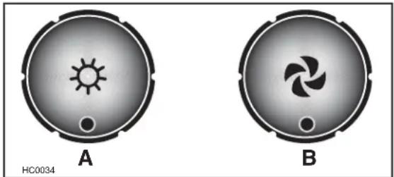
A: Halogen light knob
B: Blower speed control knob
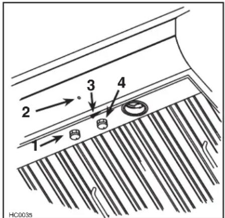
1) Halogen light knob
2) Blower operation indicator
3) ON/OFF blower switch
4) Blower speed control knob
Cooktop Lighting (Halogen)
A rotary 3-position knob (1) controls the halogen lights (OFF - low intensity - high intensity).
Blower
The blower is operated using two controls.
Use the on/off rocker switch (3) to start and stop the blower. When turned on, the blower indicator (2) turns on and the blower operates at the previous setting of the speed control (4).
Turn the speed control knob clockwise to increase blower speed – counterclockwise to decrease speed.
Heat Sentry™
This hood is equipped with a Heat Sentry thermostat. This thermostat is a device that will turn on or speed up the blower if it senses excessive heat above the cooking surface.
1) If blower is OFF - it turns blower ON to HIGH speed.
2) If blower is ON at a lower speed setting - it turns blower to HIGH speed.
When the temperature level drops to normal, the blower will return to its original setting.

WARNING: The Heat Sentry can start the blower during a range top fi re or other excessive heat situations even if the hood is turned off. In this case, it is impossible to turn the blower OFF with blower switch. If you must stop the blower, do it from the main electrical panel.
CLEANING
Baffle filters
The baffle filters should be cleaned frequently. Use a warm detergent solution. Baffle filters are dishwasher safe.
Wash more often if your cooking style generates greater grease - like frying food or wok cooking.
Grease Drip Rail
The grease drip rail should be cleaned frequently. Lift it out from the hood and use a warm detergent solution. As far the baffle filters, wash more often if your cooking style generates greater grease—like frying foods or wok cooking. Allow grease drip rail to dry completely before reinstalling it in the hood.
Blower Cleaning
Remove the filters in order to access the blower. Use a shop vacuum to clean the blower. Do not immerse in water.
Hood Cleaning
Stainless steel cleaning:
How to maintain its "BRIGHT LOOK"
Do:
- Regularly wash surfaces with clean cloth or rag soaked with warm water and mild soap or liquid dish detergent.
- Always clean in the direction of original polish lines.
- Always rinse well with clear water (2 or 3 times) after cleaning. Wipe dry completely.
- You may also use a specialized household stainless steel cleaner.
Do not:
- Use any steel or stainless steel wool or any other scrapers to remove stubborn dirt.
- Use any harsh or abrasive cleaners.
- Allow dirt to accumulate.
- Let plaster dust or any other construction residues reach the hood. During construction/renovation, cover the hood to make sure no dust sticks to stainless steel surface.
Avoid when choosing a detergent:
- Any cleaners that contains bleach will attack stainless steel.
- Any products containing: chloride, fluoride, iodide, bromide will deteriorate surfaces rapidly.
- Any combustible products used for cleaning such as acetone, alcohol, ether, benzol, etc., are highly explosive and should not be used close to a range.
KENMORE 56000 RANGE HOOD SYSTEM
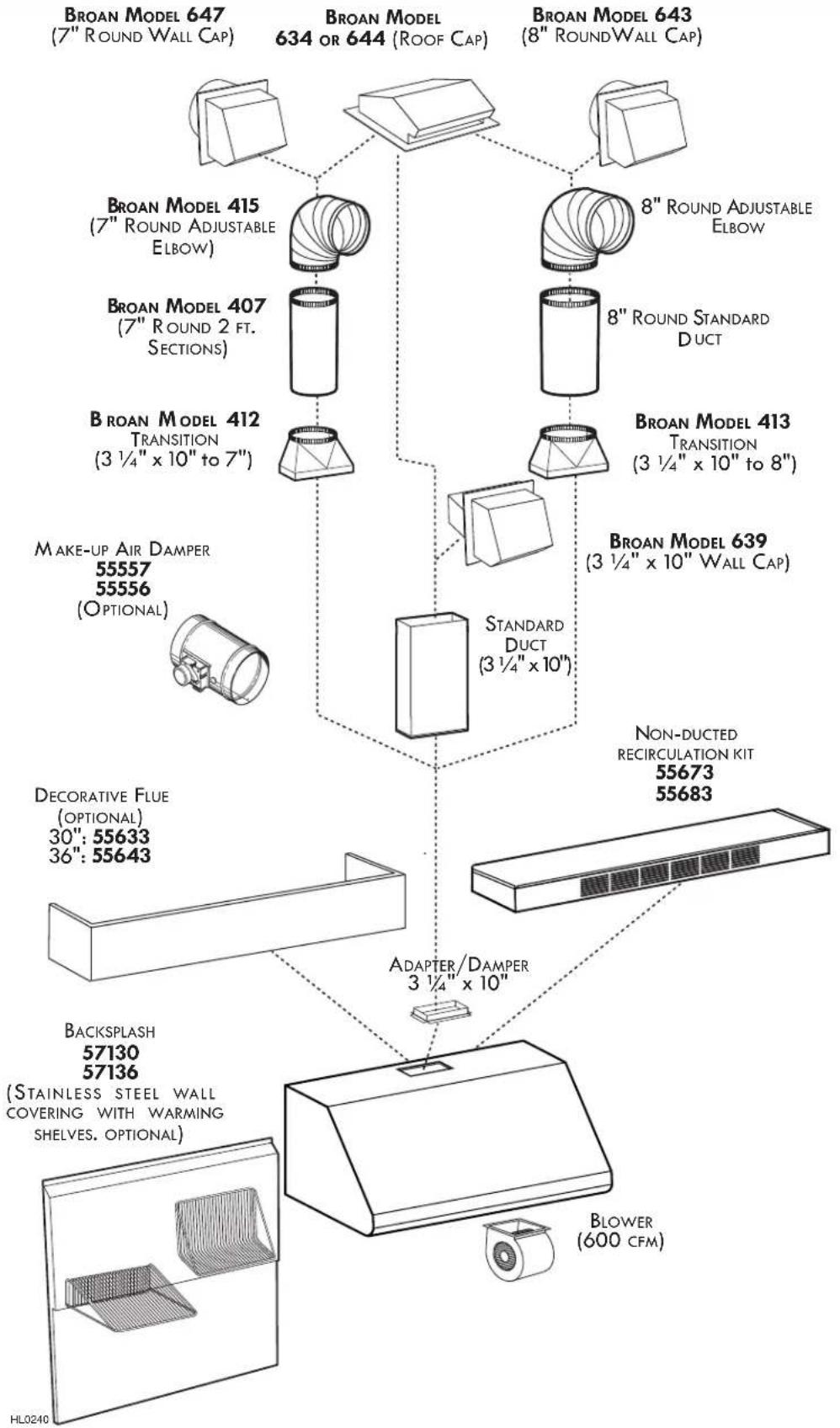
flowchart
graph TD
    A["BROAN MODEL 647 (7" ROUND WALL CAP)"] --> B["Broan Model 415 (7" ROUND ADJUSTABLE ELBOW)"]
    C["BROAN MODEL 634 or 644 (ROOF CAP)"] --> D["Broan Model 407 (7" ROUND 2 FT. SECTIONS)"]
    E["BROAN MODEL 643 (8" ROUND WALL CAP)"] --> F["Broan Model 412 TRANSITION (3 1/4" x 10" to 7")"]
    G["BROAN MODEL 413 TRANSITION (3 1/4" x 10" to 8")"] --> H["PROXIMATE TRANSITION"]
    I["PROXIMATE TRANSITION"] --> J["STANDARD DUCT (3 1/4" x 10")"]
    K["STANDARD DUCT"] --> L["Non-DUCTED RECIRCULATION KIT 55673, 55683"]
    M["ADAPTER/DAMPER 3 1/4" x 10""] --> N["ADVERTER/DAMPER 3 1/4" x 10""]
    O["DECRORATIVE FLUE (OPTIONAL) 30": 55633, 36": 55643"] --> P["BACKSPLASH 57130, 57136 (STAINLESS STEEL WALL COVERING WITH WARMING SHELVES, OPTIONAL)"]
    Q["BLOWER (600 CFM)"] --> R["BLOWER (600 CFM)"]
    style A fill:#f9f,stroke:#333
    style C fill:#f9f,stroke:#333
    style E fill:#f9f,stroke:#333
    style G fill:#f9f,stroke:#333
    style K fill:#f9f,stroke:#333
    style M fill:#f9f,stroke:#333
    style N fill:#f9f,stroke:#333
    style O fill:#f9f,stroke:#333
    style P fill:#f9f,stroke:#333
    style Q fill:#f9f,stroke:#333
    style R fill:#f9f,stroke:#333
PARTS INCLUDED WITH HOOD PAR
NOTE
Before proceeding to the installation, check the contents of the box. If items are missing or damaged, contact the manufacturer.
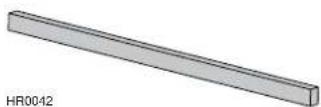
Wood strip (screwed on back of hood)
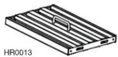
Baffl e Filter (3 per hood) (Handles are taped inside the hood)
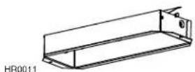
Adapter/Damper 3 ^1/4 " x 10"
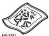
Parts Bag Including:
4 Flat Head Screws No. 10-2"
8 Screws No. 8 x 3/4"
1 Wire Clamp
2 Wire Connectors
3 Wall Anchors
3 Washers 13/64" ID x 3/4" OD
8 Mechanical Screws No. 8-32 x 1/4"
4 No. 8 x 3/8" Screws
NOT INCLUDED WITH HOOD
- 2 shielded GU10, 50 W max. halogen bulbs.
- 55633 or 55643 Decorative flue, to be installed over the hood (optional)
-
57130 or 57136 Backsplash (optional)
-
55673 or 55683 Recirculation kit, mandatory for non-ducted installation
- Transitions, duct, elbows, dampers, wall and roof caps.
- Make-up air damper 55557 or 55556 (optional)
Refer to page 5 for a complete list of venting options and model numbers.
TOOLS NEEDED FOR HOOD INSTALLATION
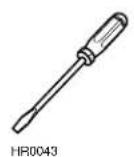
Screwdriver (Robertson or Phillips)
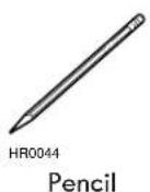
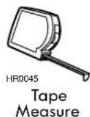
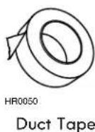
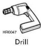
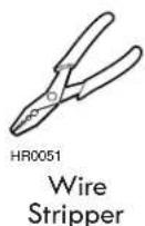
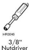
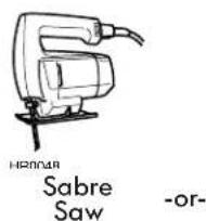
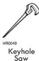

WARNING: When performing installation, servicing or cleaning the unit, it is recommended to wear safety glasses and gloves.
NON-DUCTED INSTALLATION
For non-ducted installation, a recirculation kit 55673 or 55683 (sold separately) must be installed. See installation instructions included with the non-duct kit 55673 or 55683.
INSTALL DUCTWORK
Plan where and how the ductwork will be installed.
If using 7" or 8" round ducts, use a transition. Use 2" metal foil duct tape to seal duct joints.
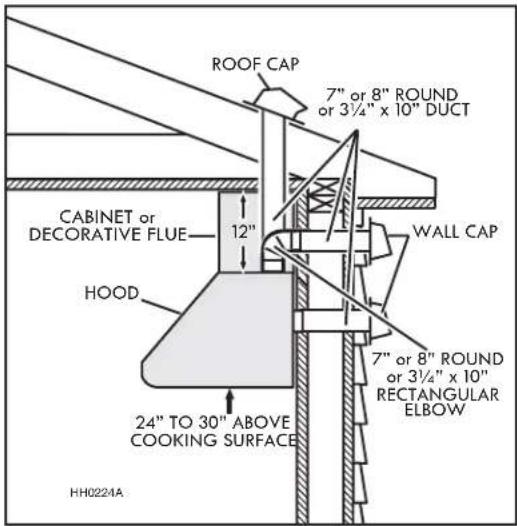
TYPICAL DUCTWORK
PREPARE THE HOOD LOCATION
The minimum hood distance above cooktop must not be less than 24". A maximum of 30" above cooktop is highly recommended for best capture of cooking impurities.
Distances over 30" are at the installer and users discretion.
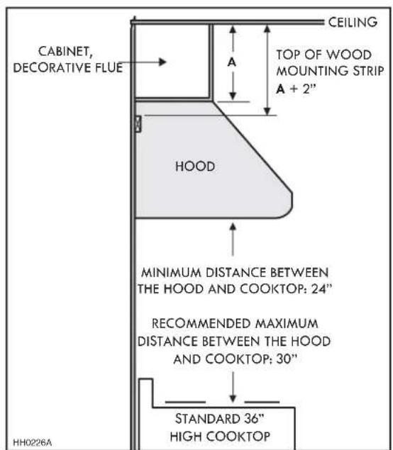
MINIMUM AND MAXIMUM DISTANCE OVER COOKTOP
PREPARE THE INSTALLATION
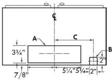
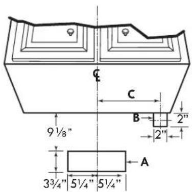
Cut-out the openings for duct (A) and power cable (B), in cabinet or wall, according to the direction of discharge chosen. See figures below.
NOTE: The cut-out opening for house wiring can be made in cabinet bottom OR wall, no matter the discharge chosen (vertical or horizontal).
VERTICAL DISCHARGE
| HOOD WIDTHS | DIMENSION C |
| 30" 13" | |
| 36" 16" |
HORIZONTAL DISCHARGE
| HOOD WIDTHS | DIMENSION C |
| 30" 13" | |
| 36" 16" |
CABINET BOTTOM VIEW
HD0588A
BACKSPLASH INSTALLATION (OPTIONAL)
Backsplash must be installed before the hood shell because it covers the backsplash top mounting screws. In order to be able to install the backsplash, make sure you have at least 18" clearance between bottom of hood and range control panel or cooktop. (See instructions packed with backsplash.)
PREPARE THE HOOD
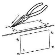
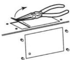
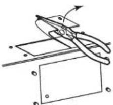
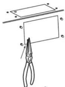
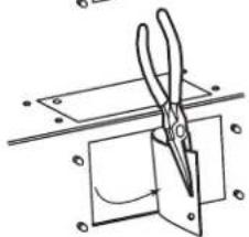
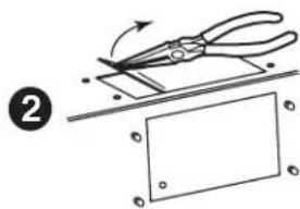
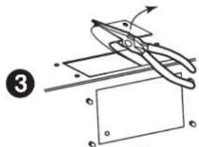
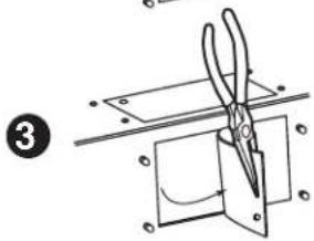
- Remove the knockout for the chosen opening (horizontal at the back of the hood or vertical on top). See illustrations below.
VERTICAL DISCHARGE
1
natural_image
Illustration of a pliers cutting a rectangular sheet with holes, no text or symbols present2
natural_image
Illustration of a pair of pliers cutting a rectangular sheet with a blank sheet, no text or symbols present.3
natural_image
Pure mechanical diagram showing a lever mechanism with no text or symbolsHORIZONTAL DISCHARGE
1
natural_image
Simple line drawing of a pair of scissors cutting a rectangular sheet with a ruler above (no text or symbols)2

natural_image
Diagram showing a cutting tool interacting with a rectangular panel, no text or symbols present3
natural_image
Pure mechanical diagram showing scissors cutting through a rectangular block with mounting holes (no text or symbols)HR0021
PREPARE THE HOOD (CONT'D)
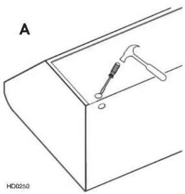
- Punch out the appropriate electrical knockout hole on top (A) or back (B) of the hood. Install the wire clamp (included in parts bag).
natural_image
Technical line drawing of a mechanical component with a hammer and screwdriver (no text or symbols)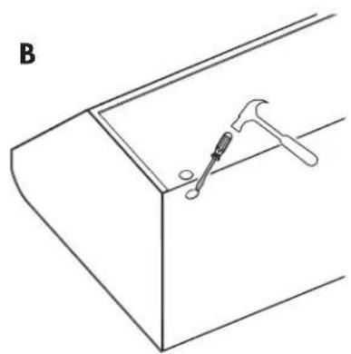
natural_image
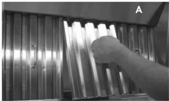
Line drawing of a tool interacting with a hammer inside a bracket (no text or symbols)- Remove the filters and the grease drip rail.
A. Remove tape on filters. Remove filters from hood and set aside. NOTE: It is recommended to start with the center one.
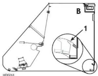
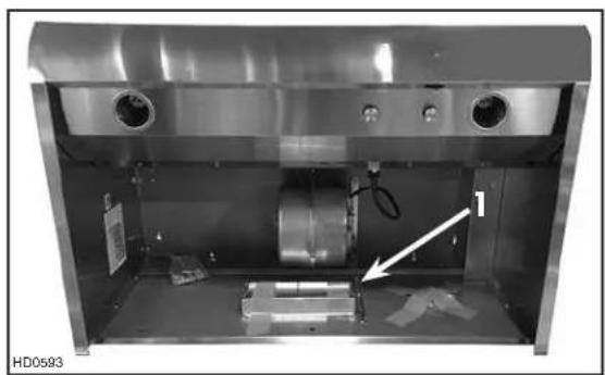
B. Remove tape on grease drip rail (1). Lift out grease drip rail and set aside.
- Remove the adapter/damper (1), taped inside the hood.
natural_image
Black-and-white photo of a hand inserting into a rack of metallic cylindrical objects, no visible text or symbolsHD0172
natural_image
Interior view of a stainless steel industrial machine with visible components and a white arrow pointing to a component (no text or symbols)HORIZONTAL DISCHARGE INSTALLATION
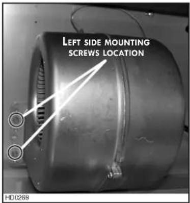
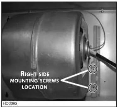
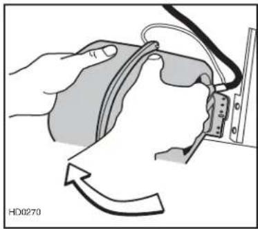
All hoods are factory shipped with the blower mounted for a vertical discharge configuration. For a horizontal discharge configuration, disassemble the blower from the inner top of the hood and mount it to the inner back panel of the hood.
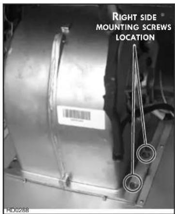
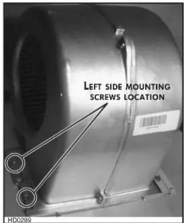
- Using a 5/16" socket, remove all blower mounting screws from the inner top of the hood. Keep the screws for further use.
- Slide the blower to disengage its fl ange from the retaining bracket.
natural_image
Illustration of a hand holding a medical device with an arrow indicating rotation (no text or symbols)-
Rotate the blower and engage its fl ange in the back wall retaining bracket.
-
Using a 5/16" socket and the screws previously removed, secure the blower to the hood.
INSTALL THE ADAPTER AND THE TRANSITION (IF NEED BE)
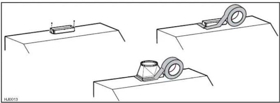
Using standard 3/8" screws provided, secure the adapter to the top (or back) of the hood. Seal the adapter to the hood using metal foil duct tape. For round ducting, install an appropriate sized transition and seal the joints with metal foil duct tape.
natural_image
Three technical diagrams showing mechanical assembly steps with no visible text or symbolsINSTALL WOOD MOUNTING STRIP
Measure and mark a level line on wall above cooktop location for the wood mounting strip (see illustration at right). Remove wood mounting strip from back of hood. Use no. 10 - 2" fl at head screws to secure the mounting strip to the drywall. Make sure to hit the wall studs.

CAUTION: Due to the weight of this hood, ensure that the wood strip is attached to all of the available studs (2 studs minimum for a 30" width hood, more as hood width increases); not into the drywall alone.
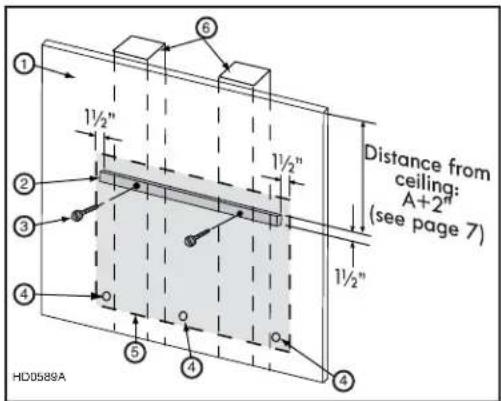
- Drywall 4. Wall anchor location
- Wood mounting strip 3. Flat head screw
- Back of hood outline 6. Wall studs
INSTALL RECIRCULATION KIT 55673 OR 55683 (NON-DUCTED INST. ONLY)
Refer to the instructions sheet included with the recirculation kit for details.
INSTALL 55633 OR 55643 OPTIONAL DECORATIVE FLUE (DUCTED INST. ONLY)
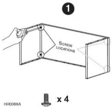
① Assemble both sides to the front using 4 no. 8 x 0.375" included screws.
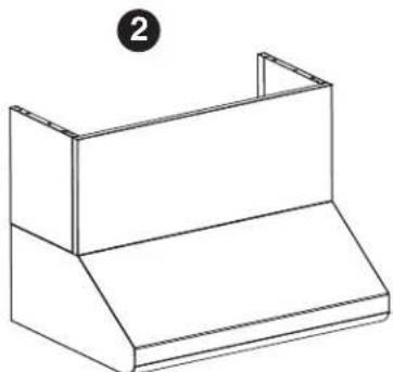
② Place the decorative flue cover on top on the range hood.
③ Secure the decorative flue cover to the top of the range hood using 6 no. 8 x 0.375" included screws.
natural_image
Isometric line drawing of a two-tiered rectangular box or shelf unit (no text or symbols)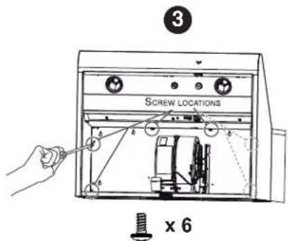
INSTALL THE HOOD

CAUTION: Hold the hood until it is completely secured to the wood mounting strip.
- Run power cable to installation location. Remove the electrical compartment cover. Insert the cable in the hood and tighten the wire clamp to secure the cable.
- Rest the back cavity of the hood on the wood mounting strip.
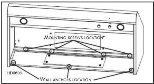
- Secure the hood to wood mounting strip with 4 screws no. 8 x 3/4" provided at locations shown. Drill (3) 3/16" size holes into the drywall for wall anchors through the existing holes in the inside hood back in the locations shown. Then, install the three wall anchors with the remaining no. 8 x 3/4" screws and the 3 washers provided.
CONNECT THE WIRING

WARNING: Risk of electrical shock. Electrical wiring must be done by qualified personnel in accordance with all applicable codes and standards. Before connecting wires, switch power off at service panel and lock service disconnecting means to prevent power from being switched on accidentally.
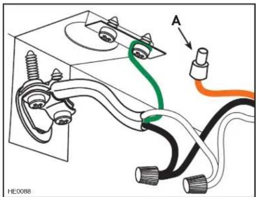
- Connect cable using provided wire connectors. Connect BLACK to BLACK, WHITE to WHITE and GREEN or bare wire under GREEN ground screw. DO NOT FORGET TO CONNECT THE GROUND.

CAUTION: The ORANGE wire (A) is for make-up air device connection only. If there is no make-up air device, never remove the cap on the ORANGE wire end.
- Reinstall wiring cover.
REINSTALL GREASE DRIP RAIL AND BAFFLE FILTERS
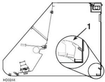
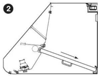
Reinstall grease drip rail (1). The illustration at right shows how to reinsert the grease drip rail into the range hood.

CAUTION: Remove protective plastic film covering filters before installing them.
NOTE: Assemble the metal handles to the filters, using provided no. 8-32 x 1/4" screws, before installing them in the hood.
It is recommended to install side filters first and finish with center one.
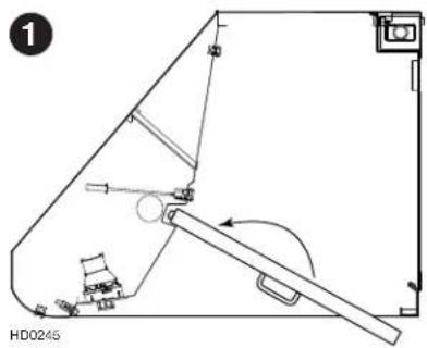
- Insert one end of the filter into the upper channel of the hood.
- Raise the other end toward the inside of the hood and insert in the grease drip rail of the hood.
natural_image
Technical line drawing of a mechanical assembly with no visible text or symbolsINSTALL LIGHT BULBS

WARNING: Do not touch lamps during or soon after operation. Burns may occur. In order to prevent the risk of personal injury, only install shielded halogen lamps. Also, never install a cool beam, a dichroic lamp, a lamp not suitable for use in recessed luminaires or identified for use in enclosed fixtures.
This hood requires 2 x 50 W max, 120 V, with GU10 base, shielded halogen lamps (not included).
- Install bulbs by placing the bulb leads into their grooves in the socket.
- Gently push upwards and turn clockwise until secure.
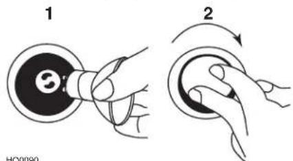
To remove bulbs, gently push upwards and turn counterclockwise to disengage bulb leads from their grooves. NOTE: If need be, use a rubber dishwashing glove to add grip when removing the bulb.
SERVICE PARTS
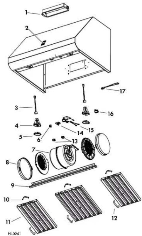
REPLACEMENT PARTS AND REPAIRS
In order to ensure your unit remains in good working condition, you must use the manufacturer genuine replacement parts only. The manufacturer genuine replacement parts are specially designed for each unit and are manufactured to comply with all the applicable certification standards and maintain a high standard of safety. Any third party replacement part used may cause serious damage and drastically reduce the performance level of your unit, which will result in premature failing. The manufacturer recommends to contact a certified service depot for all replacement parts and repairs.
Order replacement parts by PART NO., not by KEY NO.
| KEYNO. | PARTNO. | DESCRIPTION | QTY. (HOOD WIDTH) | |
| 30" 36" | ||||
| 1 SV | 13296 Adapter | /Damper 3 14 " x 10" 1 1 | ||
| 2 SV | 22258 Kenmore | PRO Logo 1 1 | ||
| 3 SV | 05917 Socket | 1 | ||
| 4 | SV09435 | Socket Holder | 2 | 2 |
| 5 | SV09434 | Light Trim | 2 | 2 |
| 6 | SV03435 | Heat SentryTM Thermostat | 1 1 | |
| 7 | SV08097 | Motor | 1 1 | |
| 8 | Roundfilter | Non-Ducted Filters (pair) | 1 | 1 |
| 9 | SV17640 | Grease Rail 30" | 1 | - |
| SV17641 | Grease Rail 36" | - | 1 | |
| 10 | SV08337 | Baffle Filter Spring (set of 6) | 1 | 1 |
| 11 | SV17606 | Baffle Filter 8.84" x 15.125" | 2 | - |
| SV17609 Baffle Filter 11.84" x 15.125" | 1 | 3 | ||
| 12 | SV07680 | Baffle Filter Handle with Screws | 3 | 3 |
| 13 | SV21722 Speed Control | 1 1 | ||
| 14 | SV08355 | Blower and Light Knobs (2 knobs) | 1 | 1 |
| 15 | SV08338 | Light Switch | 1 1 | |
| 16 | SV08339 | Blower Rocker Switch | 1 1 | |
| 17 | SV08093 | Pilot Lamp Ass'y | 1 1 | |
| * SV | 22259 Installation Guide | 1 1 | ||
| * SV | 08352 | Parts Bag:2 Wire connectors, 1 Wire clamp, 3 Wall anchors,3 Washers 13/64" ID x 3/4" OD, 4 Screws no. 8 x 3/8",8 Screws no. 8 x 3/4", 8 Mechanical Screws no. 8-32 x 1/4",4 Flat Head Screws no. 10-2" | 1 | 1 |
*Not illustrated.
LEA Y CONSERVE ESTAS INSTRUCCIONES
TABLA DE CONTENIDO GARAN
Garantía....15
natural_image
Technical line drawing of a mechanical assembly with no visible text or symbols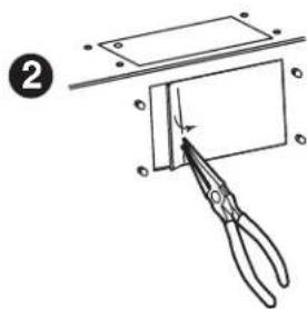
HR0021
21
natural_image
Technical line drawings of two mechanical components labeled A and B, showing tool paths and mounting points (no text or symbols beyond labels)natural_image
Black-and-white photo of a hand reaching toward a metallic panel or fixture, no visible text or symbolsnatural_image
Interior view of a stainless steel industrial machine with visible components and a numbered annotation (no readable text or symbols)natural_image
Illustration of a hand holding a device with cables and a connector, showing a curved arrow indicating rotation (no text or symbols)natural_image
Three technical line drawings showing mechanical assembly or assembly process (no text or symbols)natural_image
Isometric line drawing of a two-tiered rectangular box or shelf (no text or symbols)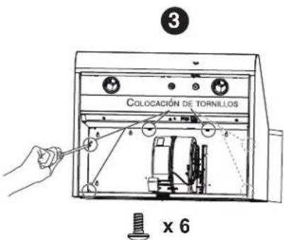
natural_image
Technical line drawing of a mechanical assembly with no visible text or symbols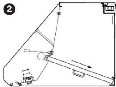
natural_image
Technical line drawing of a mechanical assembly with no visible text or symbolsFor Sears Home Services in-home repair of all Kenmore major appliances.
For the replacement parts, accessories and Use & Care Guides that you need to do-it-yourself.
For professional installation of major home appliances and items like air conditioners and water heaters.
1-844-5535667667
www.kenmore.com
In Canadah-80086946634663
www.sears.ca
Call anytime for the location of your nearest Sears Parts & Repair Service Center
1-80084884822 (U.S.A.)
1-800840946634663
To purchase a protection agreement on a serviceable product:
1-800802786655 (U.S.A.)
1-800-361-6665 (Canada)
- READ AND SAVE THESE INSTRUCTIONS
- TABLE OF CONTENTS
- KENMORE PRO LIMITED WARRANTY
- SAFETY INSTRUCTIONS
- TO REDUCE THE RISK OF A RANGE TOP GREASE FIRE:
- WARNING
- TO REDUCE THE RISK OF INJURY TO PERSONS IN THE EVENT OF A RANGE TOP GREASE FIRE, OBSERVE THE FOLLOWING\*:
- CAUTION
- OPERATION
- Cooktop Lighting (Halogen)
- Blower
- Heat Sentry™
- CLEANING
- Baffle filters
- Grease Drip Rail
- Blower Cleaning
- Hood Cleaning
- Do:
- Do not:
- Avoid when choosing a detergent:
- PARTS INCLUDED WITH HOOD PAR
- NOTE
- NOT INCLUDED WITH HOOD
- TOOLS NEEDED FOR HOOD INSTALLATION
- NON-DUCTED INSTALLATION
- INSTALL DUCTWORK
- PREPARE THE HOOD LOCATION
- PREPARE THE INSTALLATION
- BACKSPLASH INSTALLATION (OPTIONAL)
- PREPARE THE HOOD
- VERTICAL DISCHARGE
- HORIZONTAL DISCHARGE
- PREPARE THE HOOD (CONT'D)
- HORIZONTAL DISCHARGE INSTALLATION
- INSTALL THE ADAPTER AND THE TRANSITION (IF NEED BE)
- INSTALL WOOD MOUNTING STRIP
- INSTALL RECIRCULATION KIT 55673 OR 55683 (NON-DUCTED INST. ONLY)
- INSTALL 55633 OR 55643 OPTIONAL DECORATIVE FLUE (DUCTED INST. ONLY)
- INSTALL THE HOOD
- CONNECT THE WIRING
- REINSTALL GREASE DRIP RAIL AND BAFFLE FILTERS
- INSTALL LIGHT BULBS
- SERVICE PARTS
- REPLACEMENT PARTS AND REPAIRS
- LEA Y CONSERVE ESTAS INSTRUCCIONES
- TABLA DE CONTENIDO GARAN
Brand : KENMORE
Model : 233.56033
Category : Range hood