
CS355 - Service après-vente BLACK & DECKER - Free user manual and instructions
Find the device manual for free CS355 BLACK & DECKER in PDF.


| Product Type | Circular saw |
| Brand | Black & Decker |
| Model | CS355 |
| Power | 1200 W |
| Blade diameter | 190 mm |
| Maximum cutting depth (at 90°) | 65 mm |
| No-load speed | 5500 rpm |
| Power supply | Mains 230 V, 50 Hz |
| Weight | 4.2 kg |
| Dimensions (L x W x H) | 300 x 250 x 200 mm |
| Housing material | Reinforced plastic |
| Main features | Precise cutting, laser guide, depth adjustment |
| Safety | Blade brake, safety switch, anti-restart protection |
| Maintenance | Regularly clean carbon brushes, lubricate moving parts |
| Spare parts | Replacement blades, carbon brushes, parallel guide |
| Warranty | 2 years |
| Manual | Available for free PDF download |
Frequently Asked Questions - CS355 BLACK & DECKER
User questions about CS355 BLACK & DECKER
0 question about this device. Answer the ones you know or ask your own.
Ask a new question about this device
Download the instructions for your Service après-vente in PDF format for free! Find your manual CS355 - BLACK & DECKER and take your electronic device back in hand. On this page are published all the documents necessary for the use of your device. CS355 by BLACK & DECKER.
USER MANUAL CS355 BLACK & DECKER
natural_image
Technical illustration of a black-and-white cutting tool with a labeled component (no text or symbols on the device itself)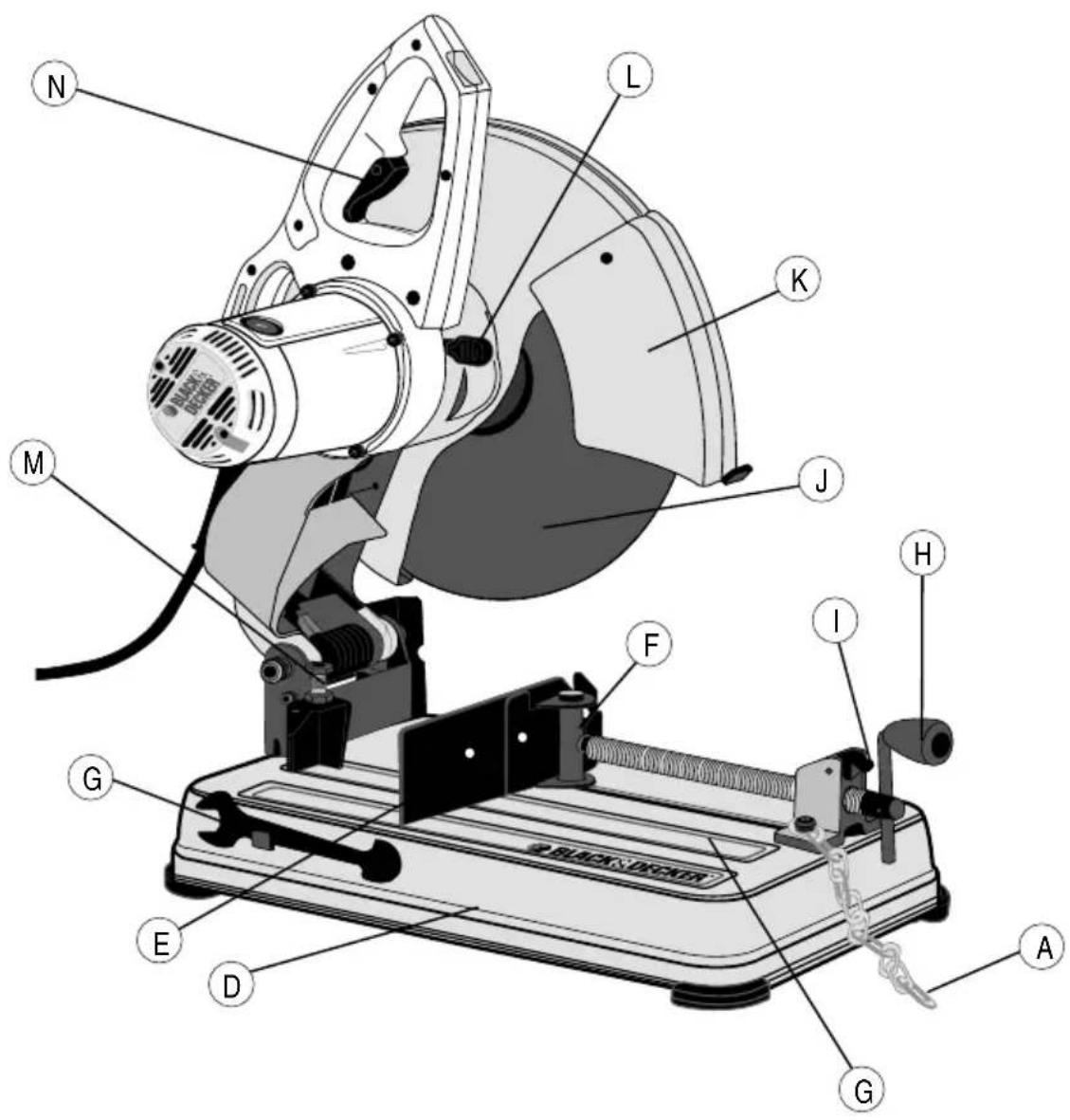
natural_image
Mechanical device labeled Fig. 3, showing a cutting machine with no visible text or symbols on the device itself.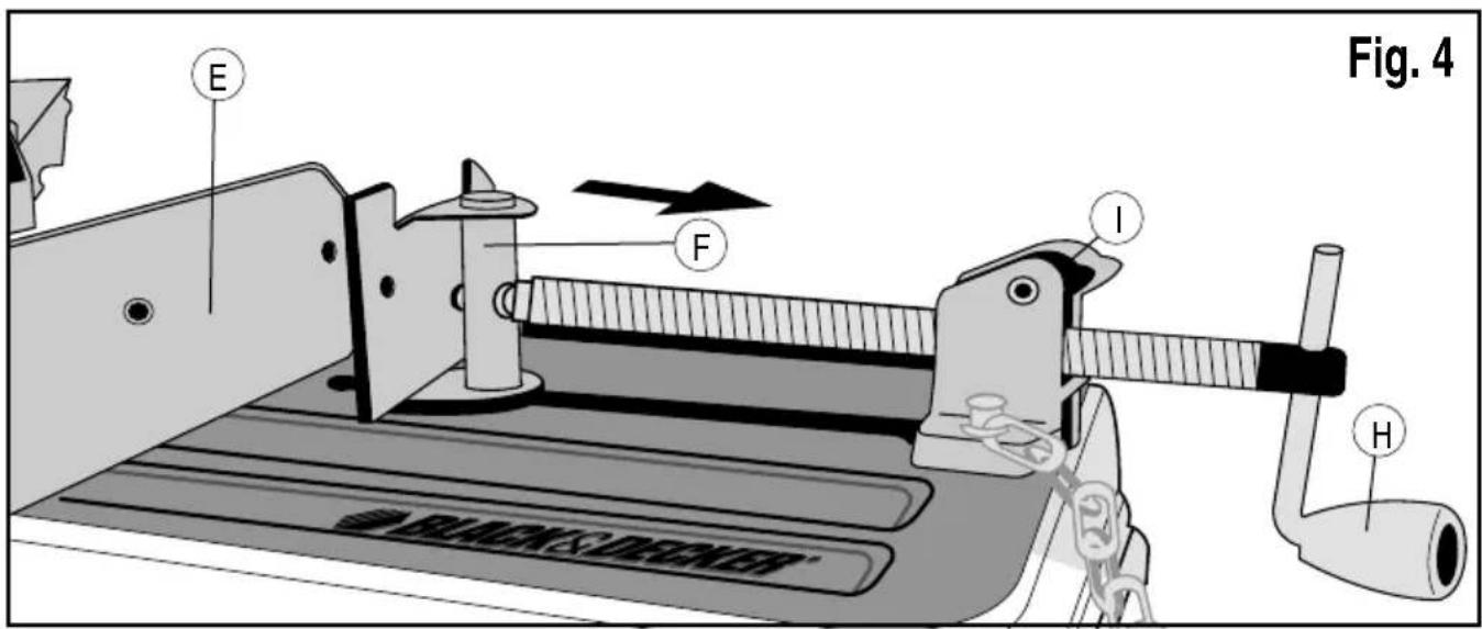
Intended use
Your Black & Decker Chop Saw has been designed for the cutting of variously shaped steel materials. This product is intended for consumer use only.
Safety instructions
General power tool safety warnings

Warning! When using power tools, always observe the safety regulations applicable in your country to reduce the risk of fire, electric shock and personal injury.
- Read all of this manual carefully before using the appliance.
- The intended use is described in this manual. The use of any accessory or attachment or the performance of any operation with this appliance other than those recommended in this instruction manual may present a risk of personal injury.
- Retain this manual for future reference.
1. Keep work area clean
Cluttered areas and benches can cause accidents.
2. Consider work area environment
Do not expose the tool to rain. Do not use the tool in damp or wet conditions. Keep the work area well lit (250 - 300 Lux). Do not use the tool where there is a risk of causing fire or explosion, e.g. in the presence of flammable liquids and gases.
3. Guard against electric shock
Prevent body contact with earthed surfaces (e.g. pipes, radiators, cookers and refrigerators). When using the tool under extreme conditions
(e.g. high humidity, when metal swarf is being produced, etc.), electric safety can be further improved by using a high sensitivity 30 mA Residual Current Device (RCD).
4. Keep other persons away
Do not let persons, especially children, not involved in the work touch the tool or the extension cord and keep them away from the work area.
5. Store idle tools
When not in use, tools must be stored in a dry place and locked up securely, out of reach of children.
6. Do not force the tool
It will do the job better and safer at the rate for which it was intended.
7. Use the right tool
Do not force small tools to do the job of a heavy duty tool. Do not use tools for purposes not intended; for example do not use circular saws to cut tree limbs or logs.
8. Dress properly
Do not wear loose clothing or jewellery, as these can be caught in moving parts. Wear protective hair covering to keep long hair out of the way. When working outdoors, preferably wear suitable gloves and non-slip footwear.
9. Use protective equipment
Always use safety glasses. Use a face or dust mask whenever the operations may produce dust or flying particles. If these particles might be considerably hot, also wear a heat-resistant apron. Wear ear protection at all times. Wear a safety helmet at all times.
ENGLISH
10. Connect dust extraction equipment
If devices are provided for the connection of dust extraction and collection facilities, ensure that these are connected and properly used.
11. Do not abuse cord
Never carry the tool by its cord. Never pull the cord to disconnect from the socket. Keep the cord away from heat, oil and sharp edges.
12. Secure workpiece
Use clamps or a vice to hold the workpiece. It is safer and it frees both hands to operate the tool.
13. Do not overreach
Keep proper footing and balance at all times.
14. Maintain tools with care
Keep cutting tools sharp and clean for better and safer performance. Follow instruction for lubricating and changing accessories. Inspect tool cords periodically and if damaged have them repaired by an authorized service facility. Inspect extension cords periodically and replace if damaged. Keep handles dry, clean and free from oil and grease.
15. Disconnect tool
Switch off and wait for the tool to come to a complete standstill before leaving it unattended. Unplug the tool when not in use, before changing any parts of the tools, accessories or attachments and before servicing.
16. Remove adjusting keys and wrenches
Always check that adjusting keys and wrenches are removed from the tool before operating the tool.
17. Avoid unintentional starting
Do not carry the tool with a finger on the switch. Be sure that the tool is switched off before plugging in.
18. Use outdoor extension cables
Before use, inspect the extension cable and replace if damaged. When using the tool outdoors, only use extension cables intended for outdoor use and marked accordingly.
19. Stay alert
Watch what you are doing, use common sense and do not operate the tool when you are tired.
20. Check for damaged parts
Before use, carefully check the tool and mains cable for damage. Check for misalignment and seizure of moving parts, breakage of parts, damage to guards and switches and any other conditions that may affect its operation. Ensure that the tool will operate properly and perform its intended function. Do not use the tool if any part is damaged or defective. Do not use the tool if the switch does not turn it on and off. Have any damaged or defective parts replaced by an authorised Black and Decker repair agent. Never attempt any repairs yourself.
21. Warning!
The use of any accessory or attachment or performance of any operation with this tool other than those recommended in this instruction manual may present a risk of personal injury.
22. Have your tool repaired by a qualified person
This tool is in accordance with the relevant safety regulations. Have your tool repaired by an authorised Black and Decker repair agent.
Repairs should only be carried out by qualified persons using original spare parts; otherwise this may result in considerable danger to the user.
Additional safety instructions for chopsaws
• Always wear regular working gloves while operating this tool.
- Keep hands away from the cutting disc. Never cut workpieces that require manual action closer than 15 cm from the rotating cutting disc.
- Do not cut workpieces less than 1.2 mm in thickness when using the cutting disc supplied with this tool.
- Do not operate this tool without guards in place.
- Do not perform any operation freehand. Use the material clamp to clamp the workpiece securely.
- Never reach in the back of the cutting disc.
- Always position the tool on a flat, stable surface that is well maintained and free of loose materials, e.g. chips and cut-offs.
- Before using, inspect the cutting disc for cracks or flaws. Discard the cutting disc if a crack or flaw is evident.
- Make sure the cutting disc is not contacting the workpiece before the tool is switched on.
- In operation, avoid bouncing the cutting disc or giving it rough treatment. If this occurs, stop the tool and inspect the cutting disc.
- Do not operate the tool while standing in line with the cutting disc. Keep other persons away from the work area.
- Be aware of cutting chips and the material being cut. They may be sharp and hot. Allow cut off parts to cool before handling.
- The spark deflector becomes hot during use. Avoid touching or adjusting the spark deflector immediately after operation.
- Switch off the tool and wait for the cutting disc to stop before moving the workpiece or changing the settings.
- After switching off, never attempt to stop the cutting disc by pressing against the side of the disc.
- Do not use cutting fluids. These fluids could ignite or cause electrical shock.
- Check that the workpiece is properly supported.
- Use the cutting discs recommended by the manufacturer only. Never use circular saw blades or any other types of toothed blades.
- The max. allowable speed of the cutting disc must always be equal to or greater than the no-load speed of the tool specified on the nameplate.
- Do not use cutting discs that do not conform to the dimensions stated in the technical data.
- Only use cutting discs that conform to EN12413.
- Ensure that the cutting disc is mounted correctly before use.
- Let the tool run at no-load in a safe position for at least 30 seconds. If there is a considerable vibration or if any other defect occurs, stop the tool and check it to determine the cause.
- Do not use cutting discs for side grinding.
- Do not cut concrete, brick, tile or ceramic materials.
ENGLISH
- Do not cut wood, plastic or synthetic materials.
- Do not cut cast-iron materials.
- Never cut magnesium materials.
- Do not cut electrically live material.
- Use this tool in a well-ventilated area. Do not operate the tool near flammable liquids, gases or dust. Sparks or hot chips from cutting or arcing motor brushes may ignite combustible materials.
- Regularly clear the ventilation slots when working in dusty conditions. If it should become necessary to clean the slots, remember to unplug the tool first.
- Always store cutting discs well-protected and in a dry place, out of reach of children.
- Warning! Use of this tool can generate dust containing chemicals known to cause cancer, birth defects or other reproductive harm. Use appropriate respiratory protection.
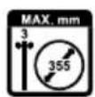
Warning! Only use a chop saw wheel with a maximum thickness of 3 mm and a maximum diameter of 355mm.
Warning! The cutting wheel will continue to rotate after the tool has been switched off.
- Use only reinforced wheels rated 4300 rpm or higher.
- Always wear eye protection, use guards, clamp work in vise, use proper respiratory protection.
The following factors are of influence to noise production:
-
the material to be cut
• the type of the cutting disc -
the feed force
- Warning! Take appropriate measures for the protection of hearing.
Residual risks
The following risks are inherent to the use of these machines:
• Injuries caused by touching the rotating parts
- Injuries caused by disruption of the cutting disc
These risks are most evident:
• Within the range of operation
- Within the range of the rotating machine parts
In spite of the application of the relevant safety regulations and the implementation of safety devices, certain residual risks cannot be avoided. These are:
- Impairment of hearing.
- Risk of accidents caused by the uncovered parts of the rotating cutting disc.
- Risk of injury when changing the disc.
- Risk of squeezing fingers when opening the guards.
Electrical safety

Your tool is double insulated; therefore no earth wire is required. Always check that the mains voltage corresponds to
the voltage on the rating plate. Never attempt to replace the charger unit with a regular mains plug.
- If the supply cord is damaged, it must be replaced by the manufacturer or an authorised Black & Decker Service Centre in order to avoid a hazard.
Voltage drops
Inrush currents cause short-time voltage drops.
Under unfavourable power supply conditions, other equipment may be affected.
If the system impedance of the power supply is lower than 0.12 Ω, disturbances are unlikely to occur.
Warning Symbols
The following symbols are found on the tool:

Warning! To reduce the risk of injury, the user must read the instruction manual.

Always wear safety goggles.

Always wear safety hearing protection.
Features
This tool includes some or all of the following features.
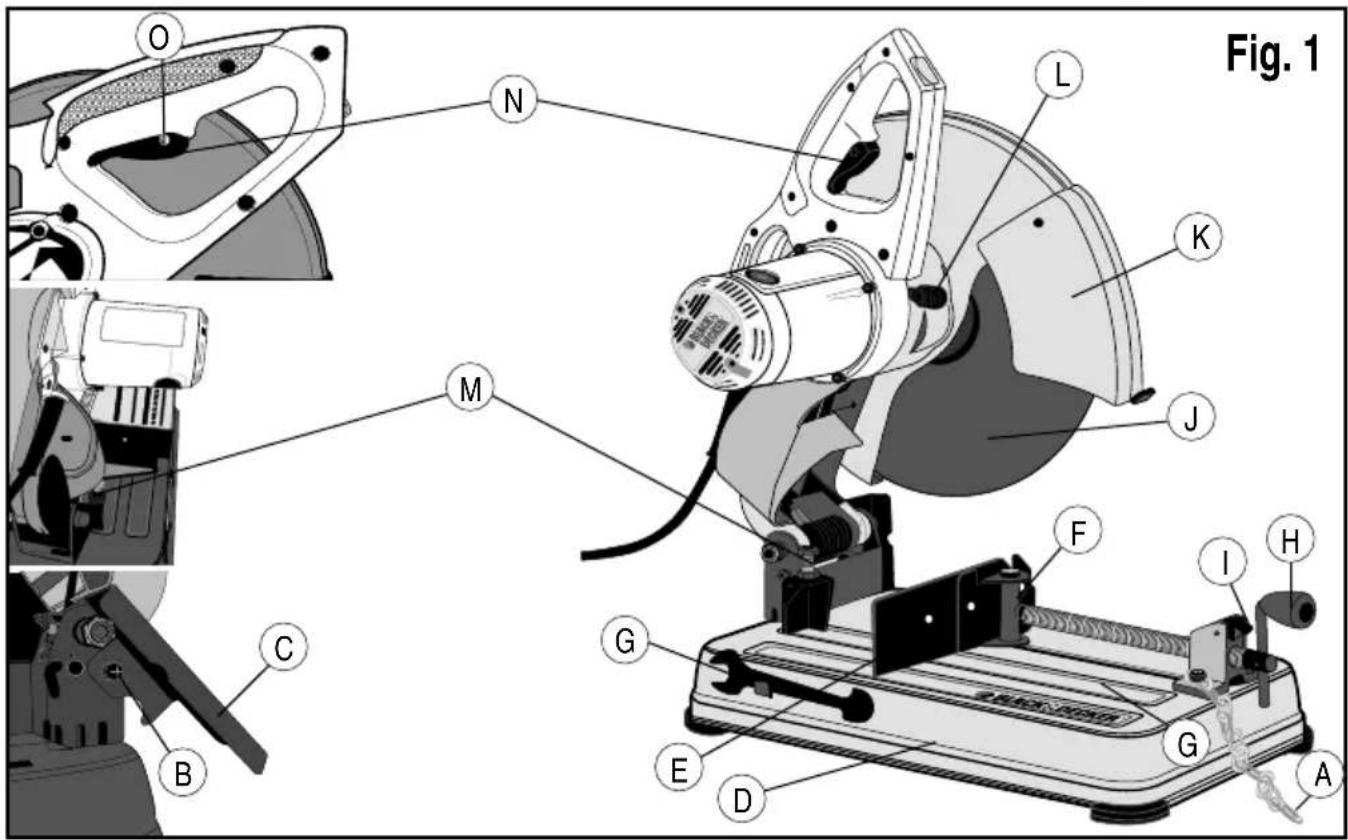
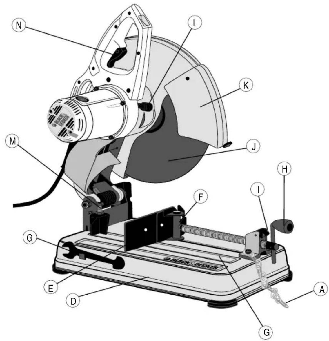
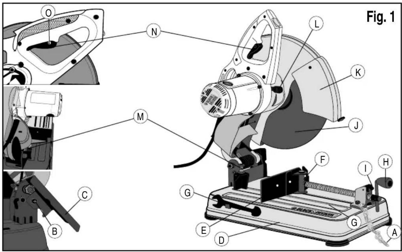
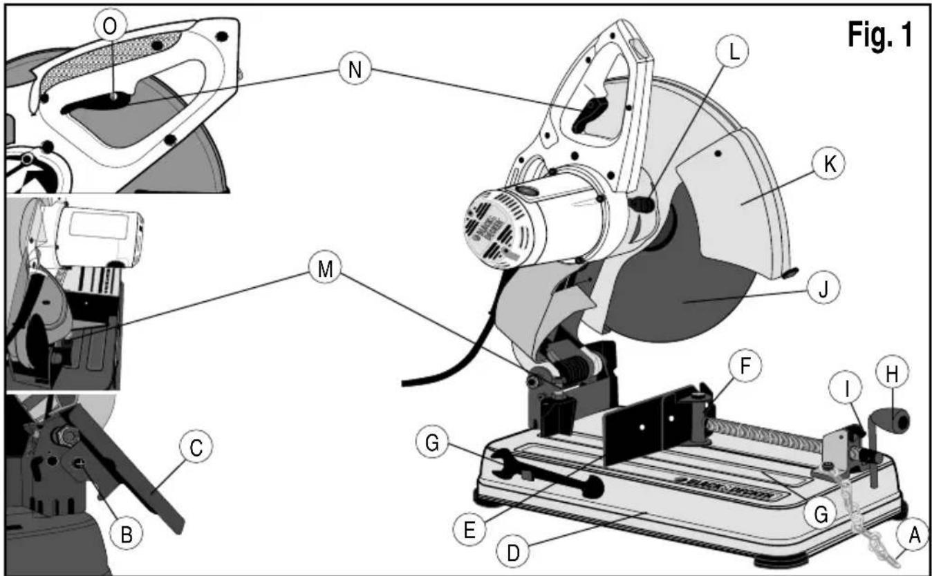
A. Lock Chain
B. Spark deflector screw
C. Spark deflector
D. Base
E. Fence
F. Vice
G. Flat Wrench
H. Crank
I. Vice Lever
J. Cutting disc
K. Guard
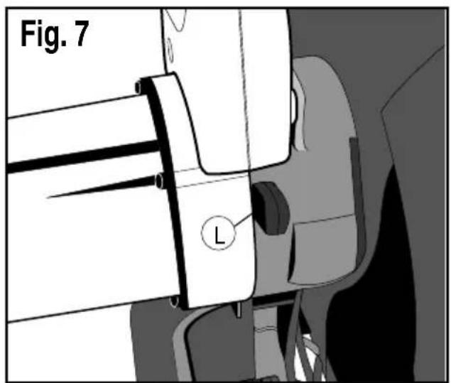
L. Spindle Lock
M. Depth Stop Bolt and Locking Nut
N. Trigger Switch
O. Padlock Hole
P. Fence Bolts
Assembly
Warning! Turn off and unplug the tool before making any adjustments or removing or installing attachments or accessories. Be sure the trigger switch is in the OFF position. Do not make any adjustment while the wheel is in motion.
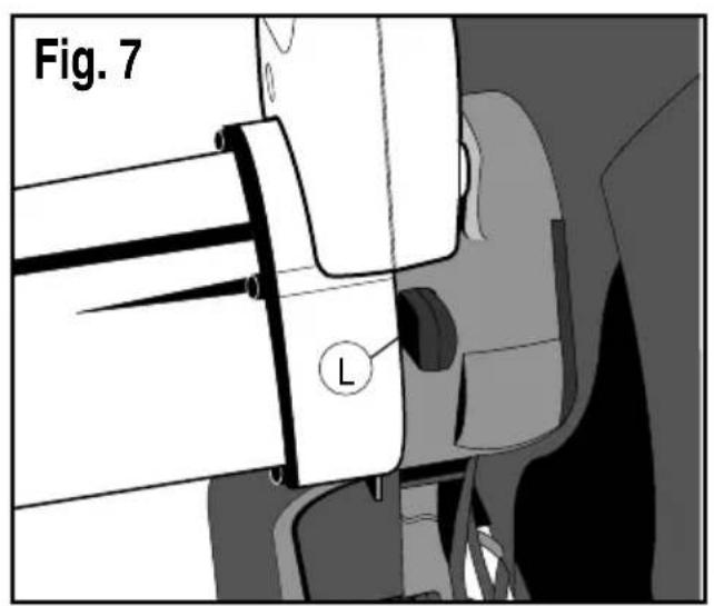
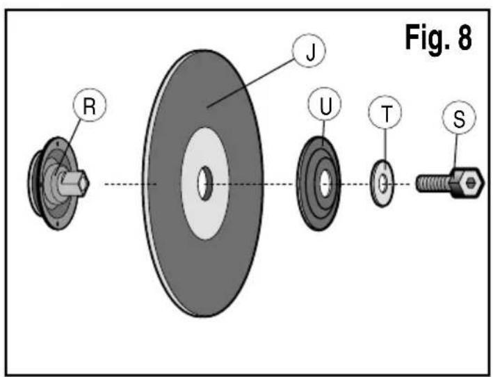
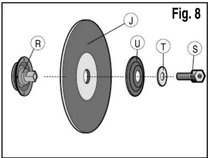
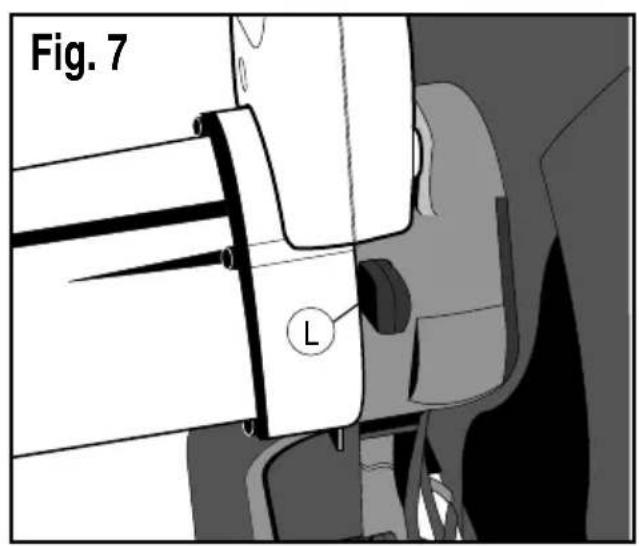
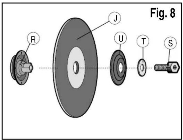
Removing and fitting a cutting disc (fig. 7 - fig 8)
- Push in the spindle lock (L).
- Rotate the cutting disc (J) until it locks.
- Using the flat wrench (G), remove the bolt (S) by turning counterclockwise and then remove the washer (T) and the retaining flange (U).
- Check that the spacer (R) is in place against the flange.
- Replace the cutting disc (J). Make sure that the new disc is placed onto the spacer (R) in the correct rotational direction.
- Secure the blade with the retaining flange (U), the washer (T) and the bolt (S).
- Push in the spindle lock (L).
- Rotate the cutting disc (J) until it locks.
- Using the flat wrench (G), tighten the bolt (S) by turning clockwise.
- Move the guard back down and release the spindle lock (L).
- Adjust the cutting depth as necessary.
ENGLISH
Adjusting the cutting depth (fig. 1)
The cutting depth can be adjusted to meet the wear of the cutting disc.
- Make a dry run with the tool switched off and check for clearance.
- If adjustment is required, proceed as follows:
- Loosen the lock nut (M) a few turns.
- Turn the depth stop bolt (M) in or out as to achieve the required cutting depth.
- Tighten the lock nut (M).
Warning: Always adjust the depth stop to its original position when replacing the cutting disc.
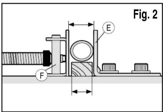
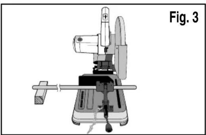
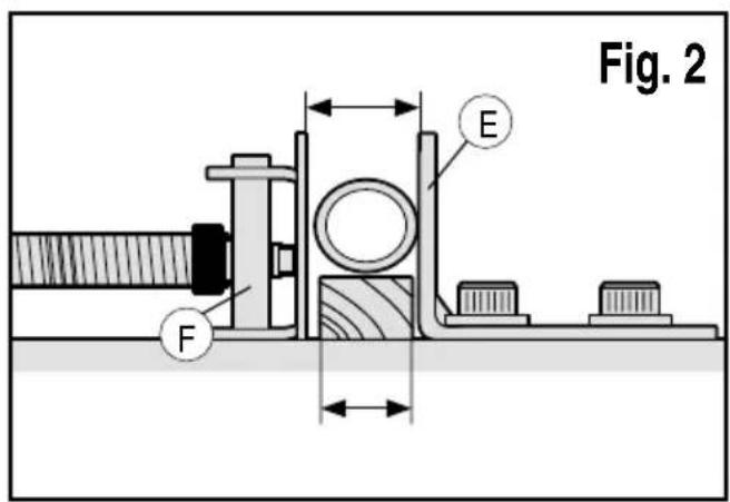
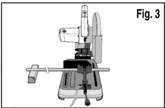
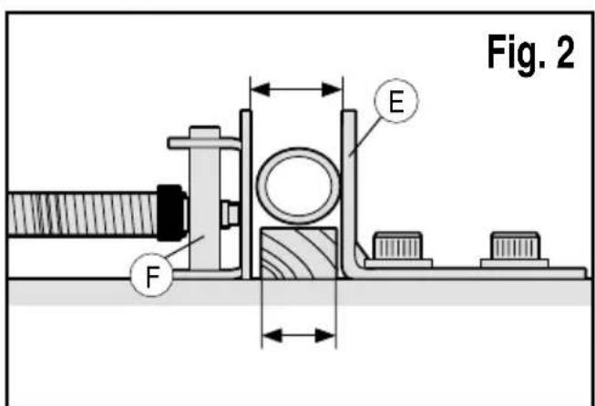
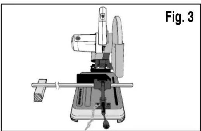
Clamping the workpiece in position (fig. 2 - fig 4)
The tool is equipped with a vise (F)
- Pull the lever (I) toward the handle (H).
- Push the vise (F) forward until the jaw is almost touching the workpiece.
- Press the lever (I) toward the jaw until it engages with the clamp shaft.
- Rotate the handle (H) clockwise and clamp the workpiece securely.
- To release the workpiece, rotate the handle (H)counterclockwise.
- To increase the cutting capacity, place a spacer block under the workpiece. The spacer block should be slightly narrower than the workpiece.
Warning: Support long workpieces using a piece of wood. Do not clamp the cut off end.
Quick travel feature (fig. 4)
The clamp has a quick travel feature.
- To release the clamp, rotate the handle (H) one or two turns counterclockwise and pull the lever (I) toward the handle (H).
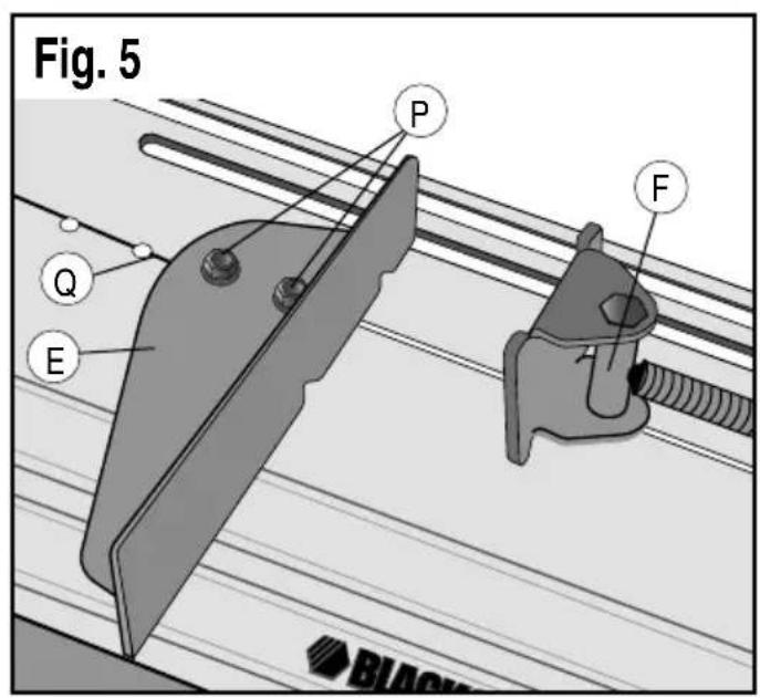
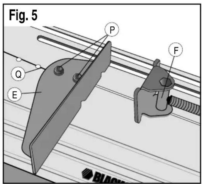
Setting the clamping position (fig. 5)
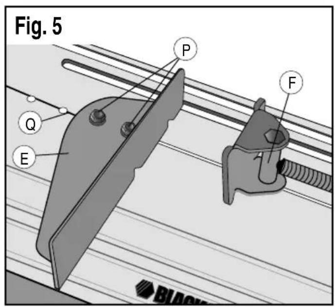
The clamping position can be set to match the cutting disc.
- Remove the fence bolts (P) using the flat wrench (G).
- Move the fence (E) as required.
- Re-fit the fence bolts (P) and tighten them to lock the fence (E).
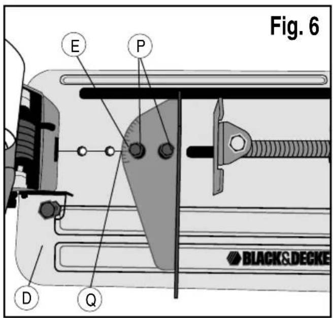
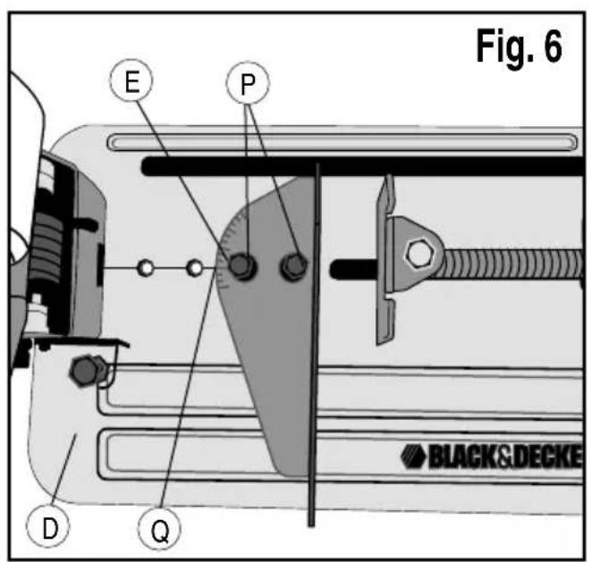
Adjusting the angle of cut (fig. 6)
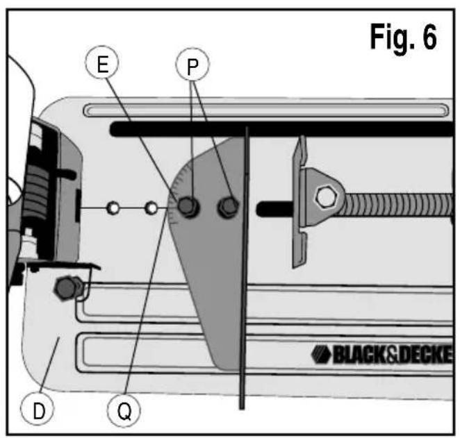
The tool can be used for mitre cuts up to 45^ .
- Loosen the fence bolts (P) to release the fence (E).
- Set the fence (E) to the required angle. The angle can be read on the scale (Q).
- Tighten the fence bolts (P) to lock the fence (E).
Checking and adjusting the mitre scale (fig. 6)
- Loosen the fence bolts (P) to release the fence (E).
- Pull down the arm and lock it in this position by attaching the lock chain (A).
-
Place a square against the fence (E) and the left side of the cutting disc creating a perfect 90^ . Check that the 0^ marking on the scale (Q) aligns with the marking on the base (D).
-
Tighten the fence bolts (P) to lock the fence (E).
- Remove the lock chain (A) and return the arm to its upper rest position.
Adjusting the spark deflector (fig. 1)
- Loosen the screw (B).
- Set the spark deflector (C) as appropriate.
- Tighten the screw (B).
Use
Warning: Always observe the safety instructions and applicable regulations.
Warning: Do not apply excessive pressure to the tool.
Warning: Avoid overloading. Should the tool become hot, let it run a few minutes under no load condition.
Cutting capacity
The wide vise opening and high pivot point provide cutting capacity for many large pieces. Use the cutting capacity chart to determine total maximum size of cuts that can be made with a new wheel.
Caution: Certain large, circular or irregularly shaped objects may require additional holding means if they cannot be held securely in vise.
Maximum cutting capacity
Note: Capacity shown on chart assumes no wheel wear and optimum fence position.
| Workpiece shape | ||||
| 90° Cutting Angle (125mm) | A = 4-7/8" (115mm) | A = 4-1/2" (115mm) | 4-1/2" x 5-1/8" (115mm x 130mm) | A = 4-1/2" x 5-3/8" (115mm x 137mm) |
| 4" x 7-5/8" (115mm x 130mm) | ||||
| 3" x 7-3/8" (115mm x 130mm) | ||||
| 45° Cutting Angle | A= 4-1/2" (115mm) (105mm x 95mm) | A = 3-13/16" (98mm) (95mm) | 4-1/2" x 3-13/16" (4-1/8" x 3-3/4" (95mm) | A = 3-13/16" (3-3/4" (95mm) |
Prior to operation:
- Install the appropriate cutting disc. Do not use excessively worn discs. The maximum rotation speed of the tool must not exceed that of the cutting disc.
- Make sure the disc rotates in the direction of the arrows on the accessory and the tool.
- Secure the workpiece.
• Always set the spark deflector correctly.
Switching on and off (fig. 1)
The on/off trigger switch (N) is mounted in the operating handle.
- To run the tool, press the on/off trigger switch (N).
- Keep the on/off switch depressed while performing the operation.
- To stop the tool, release the trigger switch (N).
Warning: Do not switch the tool on or off when under load.
Warning: To prevent unauthorized use of tool, install a standard padlock (not included) into the padlock hole (O) located in the trigger switch.

Warning! Do not cut magnesium.
ENGLISH
Consult your dealer for further information on the appropriate accessories.
Performing a cut (fig. 1)
- Place the material to be cut against the fence (E) and secure using the vise (F).
- Switch on the tool and pull down the handle to cut the workpiece. Allow the motor to reach full speed before cutting.
- Allow the disc to cut freely. Do not force.
- After completing the cut, switch off the tool and return the arm to its upper rest position.
Transporting (fig. 1)
The tool is equipped with a lock chain (A) which locks the tool in closed-down position for carrying.
Warning: Ensure that the tool is switched off and disconnected from the mains supply before transporting.
- Lower the guard (K) onto the cutting table base (D) and secure the tool in this position by securing the chain on the hook in the handle.
- Transport the tool using the carrying handles.
- To release the tool, depress the operating handle slightly and pull off the lock chain (A).
Maintenance
Your Black & Decker corded/cordless appliance/tool has been designed to operate over a long period of time with a minimum of maintenance. Continuous satisfactory operation depends upon proper appliance/tool care and regular cleaning.
Warning! Before performing any maintenance on corded/cordless appliance/tool:
- Switch off and remove the battery from the appliance.
- Keep the ventilation slots clear and regularly clean the housing with a soft cloth.
- Do not use abrasive cleaners.
Mains Plug Replacement
If a new mains plug needs to be fitted:
- Safely dispose of the old plug.
- Connect the brown lead to the live terminal of the new plug.
- Connect the blue lead to the neutral terminal.
- If the product is class I (earthed), connect the green / yellow lead to the earth terminal.
Warning! If your product is class II double insulated (only 2 wires in the cord set), no connection is to be made to the earth terminal.
Follow the fitting instructions supplied with good quality plugs.
Any replacement fuse must be of the same rating as the original fuse supplied with the product.
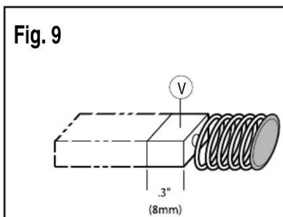
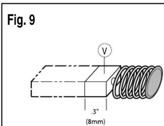
Motor brush inspection and replacement (fig. 9)
Warning! Turn off and unplug the tool. Be sure the trigger switch is in the OFF position.
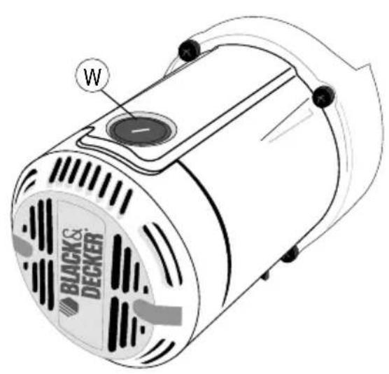
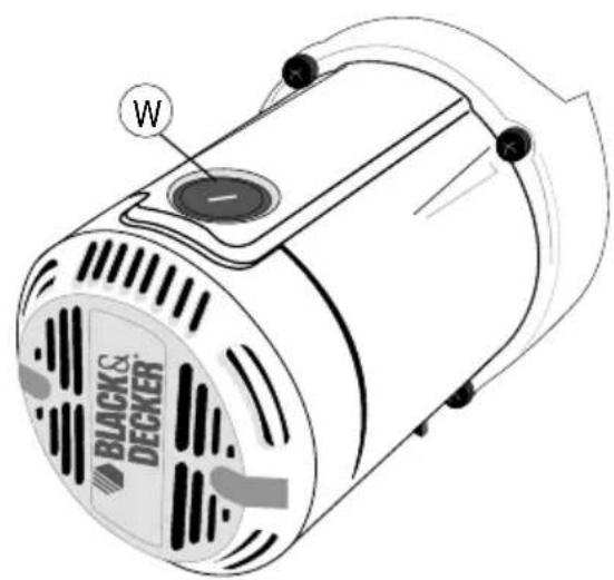
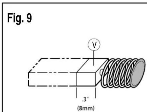
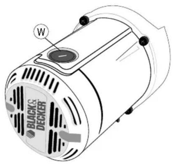
Brushes should be regularly inspected for wear. To inspect brushes, remove brush cap (W). Brushes (V) should slide freely in brush box. If brushes are worn down to .3" (8mm) as shown in Figure 9 they should be replaced.
To reinstall, push new brush back into brush box. If replacing existing brush, maintain same orientation as when removed. Replace the brush cap (do not overtighten).
Cleaning
Blowing dust and grit out of the main housing by means of an air hose is recommended and may be done as often as dirt is seen collecting in and around the air vents. Always wear proper eye and respiratory protection.
Repairs
To assure product SAFETY and RELIABILITY, repairs, maintenance and adjustment should be performed by authorized service centers or other qualified service organizations, always using identical replacement parts.
Lubrication
Closed-type, grease-sealed ball bearings are used throughout. These bearings have sufficient lubrication packed in them at the factory to last the life of the chop saw.
Accessories
Caution! The use of any other accessory not recommended for use with this tool could be hazardous.
Use only high-strength Type 1 organic bonded wheels rated 4300 rpm or higher that comply with EN12413.
Recommended accessories for use with your tool are available at extra cost from your local dealer or authorized service center.
Technical Data
| CS355(Type1) | ||
| Voltage | V_AC | 220-240 |
| Power Input | W | 2,300 |
| No-Load Speed | min^-1 | 3,800 |
| Max. Peripheral Speed m/s 80Cutting Disc | ||
| Max. Disc Diameter mm 355 | ||
| Disc Bore mm 25.4 | ||
| Max Disc Thickness mm 3 | ||
| Type Of Cutting Disc Straight, non recessed | ||
| Cross Cutting Capacity at 90° | ||
| Circular | mm | |
| Square | mm | |
| Rectangular mm 115 x 130 | ||
| Angular | mm | 137 x 137 |
| Cross Cutting Capacity at 45° | ||
| Circular | mm | 115 |
| Square | mm | 98 x 98 |
| Rectangular mm | 105 x 95 | |
| Angular | mm | 95 x 95 |
| Weight | kg | 18 |
125
115
ENGLISH
Protecting the environment
arate collection. This product must not be disposed of with normal household waste.
Should you find one day that your Black & Decker product needs replacement, or if it is of no further use to you, do not dispose of it with other household waste. Make this product available for separate collection.
- Black & Decker provides a facility for recycling Black & Decker products once they have reached the end of their working life. This service is provided free of charge. To take advantage of this service please return your product to any authorised repair agent who will collect them on our behalf.
- You can check the location of your nearest authorised repair agent by contacting your local Black & Decker office at the address indicated in this manual. Alternatively, a list of authorized Black & Decker repair agents and full details of our after-sales service and contact are available on the Internet at: www.2helpU.com.
Warranty
If a Black & Decker product becomes defective due to a material or manufacturing defect, within 12 months from the date of purchase, Black & Decker guarantees to replace defective parts or replace such products to ensure minimum inconvenience to the customer unless:
- The product has been subjected to misuse or neglect.
- The product has sustained damage through foreign objects, substances or accidents.
- Repairs have been attempted by persons other than authorised repair agents or Black & Decker service staff.
To claim on the warranty, you will need to submit proof of purchase to the seller or an authorised repair agent. You can check the location of your nearest authorised repair agent by contacting your local Black & Decker office at the address indicated in this manual. Alternatively, a list of authorised Black & Decker repair agents and full details of our after-sales service and contacts are available on the Internet at: www.2helpU.com.
Please visit our website www.blackanddecker.ae to register your new Black & Decker product and to be kept up to date on new products and special offers. Further information on the Black & Decker brand and our range of products is available at www.blackanddecker.ae.
ARABIC
natural_image
Mechanical device labeled Fig. 3 showing a clamping mechanism with no visible text or symbols on the device itself.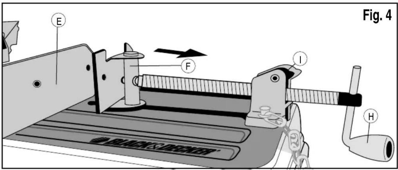
natural_image
Technical line drawing of a black-and-decker electric motor with labeled ports (no text or symbols beyond branding)ARABIC
natural_image
Mechanical device labeled Fig. 3, showing a cutting machine with no visible text or symbols on the device itself.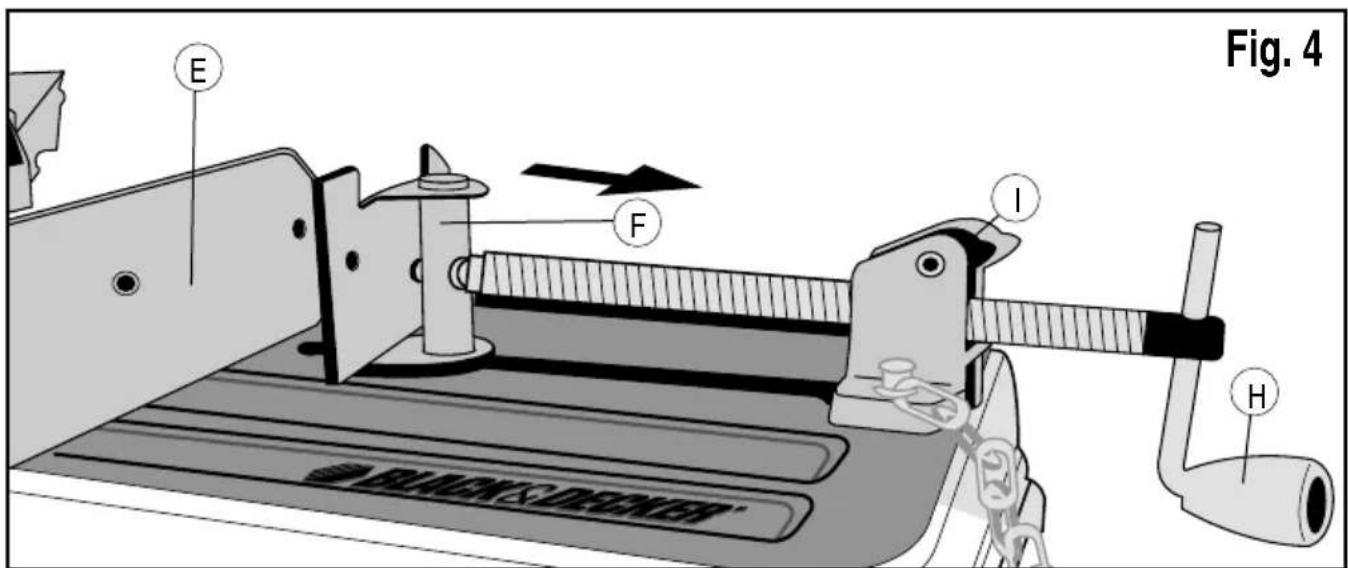
Utilisation
| 90 ^ angle de coupe | A = 4-7/8" (125 mm) (145 mm) | A = 4-1/2" (115 mm) (115mm x 130mm) | 4-1/2" x 5-1/8" (115mm x 137mm) | A = 4-1/2" x 5-3/8" |
| (115mm x 130mm) | ||||
Transport (figure 1)
Names & Addresses for Black & Decker Service Concessionaries
ALGERIA: Sarl Outillage Corporation, 08 Rue Med Boudiaf - Cheraga - Algiers, Algeria. Tel: (213-21) 375130, Fax: (213-21) 369667. AZERBAIJAN: Royalton Holdings Ltd. 41 Khagani St. Apt. 47 AZ 1001, Baku. Tel: (994-12) 4935544, Fax: (994-12) 5980378. BAHRAIN: Alfouz Services Co. WLL., P.O. Box 26562, Tubli, Manama. Tel: (973) 17783562, Fax: (973) 17783479. EGYPT: El-Farab S.A.E 15 - Nabil El Wakkad Street, Dokki, Giza. Tel: (202) 37603946, Fax: 33352796. ETHIOPIA: Seif Tewik Sherif, Arada Sub-City, Kebele 01/02, Global Insurance Building, 2nd Floor, Room 43, P.O. Box 2525, Addis Ababa, Ethiopia. Tel: (251-11) 1563968/ 1563969, Fax: (251-11) 1558009. IRAQ: Al Sard Co. for General Trading Ltd. Jbara Bldg. 3Flr, Al Rasheed St. Bagdad. Tel: (964) 18184102. Sakhar Group, Arrassat al-hindya Al Masbah, Bagdad. (964) 7400144446. JORDAN: Palestine Bldg. Matl. (Bashiti Hardware), 93 King Abdullah 2nd Street, Opp. ELBA House, P.O. Box 3005, Amman 11953, Tel: (962-6) 5349098, Fax: (962-6) 5330731. KENYA: Dextron Tools Ltd., P.O. Box 20121-00200, Shariff House, Kimathi Street, Nairobi. Tel: (254-20) 6905000/ 2358021, Fax: (254-20) 6905111/ 6905112. KUWAIT: Al Omar Technical Co., P.O. Box 4062, 13041 Safat, Kuwait. Tel: (965) 24848595/ 24840039, Fax: (965) 24845652. Fawaz Al Zayani Establishment, P.O. Box 42426, Shop No. 18, Al Humaizi Commercial Complex, Khalifa Al Jassim, Shuwaikh, Kuwait. Tel: (965) 24828710, Fax: (965) 24828716. LEBANON: Est. Shaya & Azar S.A.R.L., Boulevard, Jdeideh, Mar Takla-Bouchrieh, P.O. Box 90545, Jdeideh, Beirut. Tel: (961-1) 872305/ 872306, Fax: (961-1) 872303. LIBYA: (Benghazi) Sniydel st., Amr Ibn EL-Aas Rd. Tel: (+218) 92 5771120. (Tripoli) Al Barniq Service Center, Mokhazin elsukar st., ElFallah. Tel: (+218) 21 4808019. (Misrata) Al Hilal Service Center, Tawergha st. Tel: (+218) 51 2626743. MAURITIUS: Robert le Marie Limited, Old Moka Road, Bell Village, P.O. Box 161, Port Louis. Tel: (230) 2121865/ 2122847, Fax: (230) 2080843. MOROCCO: Ets. Louis Guillaud & Cie, 31, Rue Pierre Parent, Casablanca-21000. Tel: (+212) 522 305971, Fax: (+212) 522 444518. NIGERIA: Meridian Power Tools Ltd., Gr. Floor, #1 Alhaji Masha Road, Next to Teslim Balogun Stadium, Near National Stadium, Surulere, Lagos. Tel: (234-1) 7740431/ 7740410, Fax: (234-1) 7913798. OMAN: Al Jizzi Company LLC, P.O. Box 1704, P.C. 112 Ruwi, Oman. Tel: (968) 24832618/ 24835153, Fax: (968) 24831334. Al Hassan Technical & Construction Supplies Co. LLC., P.O. Box 1948, P.C. 112, Ruwi, Oman. Tel: (968) 24810575/ 24837054, Fax: (968) 24810287/ 248333080. Khimji Ramdas, P.O. Box 19, Post Code 100, Ghala, Muscat, Oman. Tel: (968) 24595906/ 907, Fax: (968) 24852752. Oman Hardware Co. LLC., P.O. Box 635, Ruwi-112. Tel: (968) 24815131, Fax: (968) 24816491. Oman Marketing & Service Co. (Omasco), P.O. Box 2734, Behind Honda Showroom, Wattayah, Oman. Tel: (968) 24560232/ 24560255, Fax: (968) 24560993. Oman Marketing & Service Co. (Omasco), Al Ohi, Sohar, Oman. Tel: (968) 26846379, Fax: (968) 26846379. Oman Marketing & Service Co. (Omasco), Sanaya, Salalah, Oman. Tel: (968) 23212290, Fax: (968) 23210936. PAKISTAN: Ammar Service & Spares, 60-Bank Arcade, Serai Road, Karachi, Pakistan. Tel: (92-21) 32426905, Fax: (92-21) 32427214. ZIT Co., Nasir & Bros., 2nd Floor, Qadri Center, Chowk Dalgran, Railway Road, Lahore. Tel: (92-42) 37670839, Fax: (92-42) 37652989. QATAR: Al Muftah Service Centre, Al Wakrah Road, P.O. Box 875, Doha, Qatar. Tel: (974) 4650880/ 4650110/ 4446868, Fax: (974) 4441415/ 4662599. Shaheen Electrical Works & Trading Co. WLL., Gate 34, St.44 Industriala Area, P.O. Box 9756, Doha. Tel: (974) 4600230/ 4600525, Fax: (974) 4601338. Teyseer Industrial Supplies & Services Co. WLL., 55, Al Wakalat St. (Between St. 18 & 19) Salwa Industrial Area, P.O. Box 40523, Doha, Qatar. Tel: (974) 4581536, Fax: (974) 4682024. SAUDI ARABIA: (Al Bahr) Mohamed Ahmed Bin Aiz Est., P.O. Box 530, Yanbu, Al Bahr. Tel: (966-4) 3222626/ 3228867, Fax: (966-4) 3222210. (Al Khobar) Fawaz Ebrahim Al Zayani Trading Est., P.O. Box 76026, Al Khobar # 31952, Tel: (966-3) 8140914, Fax: (966-3) 8140824. MSS (Al-Mojil Supply & Services) P.O. Box 450, Jubail 31951, Opp. Gulf Bridge Library & Riyadh House. Tel: (966-3) 3612850/ 3624487/ 3621729, Fax: (966-3) 3623589/ 3620783. (Dammam) Al Bawardi Tools & Hardware, P.O. Box 112, Dammam 31411. Tel: (966-3) 8330780/ 8348585 ext. 24, Fax: (966-3) 8336303. (Jeddah) Al Bawardi Tools & Hardware, P.O. Box 16905, Jeddah-21474. Tel: (966-2) 6444547, Fax: (966-2) 6439024. EAC (Al Yousef Contg. & Trdg. Est.), P.O. Box 30377, Jeddah -21477, Tel: (966-2) 6519912, Fax: (966-2) 6511153. (Madina) Garziz Trading for Bldg Mat & Decoration, P.O. Box 3364, Madina. Tel: (966-4) 8261490/ 8227636, Fax: (966-4) 8265741. (Riyadh) Al Bawardi Tools & Hardware, P.O. Box 68, Riyadh 11411. Tel: (966-1) 4484999, Fax: (966-1) 4487877. Industrial Material Organization (IMO), P.O. Box 623, Rail Street, Riyadh. Tel: (966-1) 4028010, Fax: (966-1) 4037970. Sulatn Garment factory (RSC), P.O. Box 29912, Riyadh 11467. Tel: (966-1) 4055148/ 4042889, Fax: (966) 4055148. SOUTH AFRICA: Trevco Power Tool Service 14 Steenbok Street, Koedoespoort, OIIBG; Pretoria South Africa.Tel:(ZY-BG)(ZY-BG)(ZY-BG)(ZY-BG)(ZY-BG)(ZY-BG)(ZY-BG)(ZY-BG)(ZY-BG)(ZY-BG)(ZY-BG)(ZY-BG)(ZY-BG)(ZY-BG)(ZY-BG)(ZY-BG)(ZY-BG)(ZY-BG)(ZY-BG)(ZY-BG)(ZY-BG) Industrial Material Organization (IMO), P.O.BX(PO), RAY(PO), RAY(PO), RAY(PO), RAY(PO), RAY(PO), RAY(PO), RAY(PO), RAY(PO), RAY(PO), RAY(PO), RAY(PO), RAY(PO), RAY(PO), RAY(PO), RAY(PO), RAY(PO), RAY(PO), RAY(PO), RAY(PO), RAY(PO), RAV(PO), RAV(PO), RAV(PO), RAV(PO), RAV(PO), RAV(PO), RAV(PO), RAV(PO), RAV(PO), RAV(PO), RAV(PO), RAV(PO), RAV(PO), RAV(PO), RAV(PO), RAV(PO), RAV(PO), RAV(PO), RAV(PO), RAV(PO), RRV(PO), RRV(PO), RRV(PO), RRV(PO), RRV(PO), RRV(PO), RRV(PO), RRV(PO), RRV(PO), RRV(PO), RRV(PO), RRV(PO), RRV(PO), RRV(PO), RRV(PO), RRV(PO), RRV(PO), RRV(PO), RRV(PO), RRV(PO), RAV(PO), RAV(PO), RAV(PO), RAV(PO), RAV(PO), RAV(PO), RAV(PO), RAV(PO), RAV(PO), RAV(PO), RAV(PO), RAV(PO), RAV(PO), RAV(PO), RAV(PO), RAV(PO), RAV(PO), RAV(PO), RAV(PO), RRAV(PO), RRAV(PO), RRAV(PO), RRAV(PO), RRAV(PO), RRAV(PO), RRAV(PO), RRAV(PO), RRAV(PO), RRAV(PO), RRAV(PO), RRAV(PO), RRAV(PO), RRAV(PO), RRAV(PO), RRAV(PO), RRAV(PO),

BLACK & DECKER®
WARRANTY REGISTRATION CARD
YOUR NAME/الإسم
- Intended use
- Safety instructions
- General power tool safety warnings
- Keep work area clean
- Consider work area environment
- Guard against electric shock
- Keep other persons away
- Store idle tools
- Do not force the tool
- Use the right tool
- Dress properly
- Use protective equipment
- ENGLISH
- Connect dust extraction equipment
- Do not abuse cord
- Secure workpiece
- Do not overreach
- Maintain tools with care
- Disconnect tool
- Remove adjusting keys and wrenches
- Avoid unintentional starting
- Use outdoor extension cables
- Stay alert
- Check for damaged parts
- Warning!
- Have your tool repaired by a qualified person
- Additional safety instructions for chopsaws
- Residual risks
- Electrical safety
- Voltage drops
- Warning Symbols
- Features
- Assembly
- Removing and fitting a cutting disc (fig. 7 - fig 8)
- Adjusting the cutting depth (fig. 1)
- Clamping the workpiece in position (fig. 2 - fig 4)
- Quick travel feature (fig. 4)
- Setting the clamping position (fig. 5)
- Adjusting the angle of cut (fig. 6)
- Checking and adjusting the mitre scale (fig. 6)
- Adjusting the spark deflector (fig. 1)
- Use
- Cutting capacity
- Maximum cutting capacity
- Prior to operation:
- Switching on and off (fig. 1)
- Consult your dealer for further information on the appropriate accessories.
- Performing a cut (fig. 1)
- Transporting (fig. 1)
- Maintenance
- Mains Plug Replacement
- Motor brush inspection and replacement (fig. 9)
- Cleaning
- Repairs
- Lubrication
- Accessories
- Protecting the environment
- Warranty
- ARABIC
- Utilisation
- Transport (figure 1)
- Names & Addresses for Black & Decker Service Concessionaries
- BLACK & DECKER®
- WARRANTY REGISTRATION CARD
Brand : BLACK & DECKER
Model : CS355
Category : Service après-vente