
MCSCTE12BG1 - Cooker Magic Chef - Free user manual and instructions
Find the device manual for free MCSCTE12BG1 Magic Chef in PDF.


| Product Type | Electric Cooktop |
| Brand | Magic Chef |
| Model | MCSCTE12BG1 |
| Glass Width | 12" (305 mm) |
| Glass Depth | 21.5" (546 mm) |
| Frame Width | 11.4" (290 mm) |
| Frame Depth | 19.3" (490 mm) |
| Cooktop Height | 2" (52 mm) |
| Cooktop Height (including conduit) | 3.15" (80 mm) |
| Net Weight | 14.1 lbs (6.4 kg) |
| Voltage Rating | 240 V, 60 Hz (also 120 V, 60 Hz) |
| Power Rating | 3000 W (240 V) / 2600 W (120 V) |
| Cooking Zones | 4 single zones, 1 dual zone (single/dual) |
| Surface Material | Ceramic glass |
| Hot Surface Indicator | Yes, light glows until surface cools |
| Control Type | Push-in rotary knobs |
| Installation Type | Drop-in, over undercounter oven or cabinets |
| Electrical Requirements | 40-amp circuit, 8 gauge copper wire, 3 or 4-wire connection |
| Warranty | 1 year parts and labor |
| Recommended Cookware | Flat-bottomed, medium-to-heavy thickness, various materials |
| Cleaning | Mild soap and water, avoid abrasives; use cooktop scraper for spills |
Frequently Asked Questions - MCSCTE12BG1 Magic Chef
User questions about MCSCTE12BG1 Magic Chef
0 question about this device. Answer the ones you know or ask your own.
Ask a new question about this device
Download the instructions for your Cooker in PDF format for free! Find your manual MCSCTE12BG1 - Magic Chef and take your electronic device back in hand. On this page are published all the documents necessary for the use of your device. MCSCTE12BG1 by Magic Chef.
USER MANUAL MCSCTE12BG1 Magic Chef
12-Inch Electric Cooktop
User's Manual
natural_image
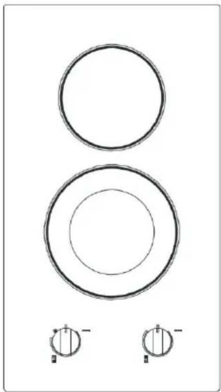
Two concentric circles with small circular symbols below, no text or labels present
natural_image
Two large circles with small circular symbols below, no text or labels presentModel MCSCTE12BG1
MCSCTE12BG2
PLEASE READ THIS MANUAL CAREFULLY BEFORE USING YOUR ELECTRIC RANGE AND KEEP IT FOR FUTURE REFERENCE.

PRODUCT REGISTRATION
Thank you for purchasing this Magic Chef® product. The first step to protect your new product is to complete the product registration on our website: www.mcappliance.com/register. The benefits of registering your product include the following:
- Registering your product will allow us to contact you regarding a safety notification or product update.
- Registering your product will allow for more efficient warranty service processing when warranty service is required.
- Registering your product could act as your proof of purchase in the event of insurance loss.
Once again, thank you for purchasing this Magic Chef product.
CONTENTS
PRODUCT REGISTRATION 2
PRECAUTIONS 4
IMPORTANT SAFETY INSTRUCTIONS 5
SPECIFICATIONS....6
PARTS AND FEATURES 7
INSTALLATION REQUIREMENTS....8
INSTALLATION INSTRUCTIONS .... 11
BEFORE USE 15
OPERATION INSTRUCTIONS.... 17
CARE AND MAINTENANCE....19
TROUBLESHOOTING.... 20
LIMITED WARRANTY 21
PRECAUTIONS
EXPLANATION OF SYMBOLS
WARNING
Hazards or unsafe practices which COULD result in severe personal injury or death.
CAUTION
Hazards or unsafe practices which COULD result in minor personal injury.
THIS PRODUCT IS INTENDED FOR HOUSEHOLD USE ONLY
⚠ WARNING: Read and understand all safety precautions. Failure to follow all instructions described in this user manual may result in electric shock, fire and/or serious personal injury. The warnings, cautions and instructions discussed in this user manual cannot cover all possible conditions and situations that may occur.
IMPORTANT SAFETY INSTRUCTIONS
⚠ WARNING: To reduce the risk of fire, electrical shock, injury to persons, or damage when using the cooktop, follow basic precautions, including the following.
CAUTION: DO NOT store items in cabinets above the cooktop that are of interest to children. Children climbing on the cooktop to reach items could be seriously injured.
- Be sure your cooktop is properly installed and grounded by a qualified technician.
- DO NOT repair or replace any part of the cooktop unless specifically recommended in the manual. All other servicing SHOULD be referred to a qualified technician.
- Wear proper apparel. Loose-fitting or hanging garments SHOULD NEVER be worn while using the cooktop.
- Flammable materials SHOULD NOT be stored near surface units.
- Only certain types of glass, glass/ceramic, ceramic, earthenware, or other glazed utensils are suitable for cooktop service without breaking due to the sudden change in temperature.
- Utensil handles SHOULD be turned inward and not extend over adjacent surface units. To reduce the risk of burns, ignition of flammable materials, and spillage due to unintentional contact with the utensil, the handle of a utensil SHOULD be positioned so that it is turned inward, and does not extend over adjacent surface units.
- DO NOT use water on grease fires. Smother fire or flame or use dry chemical or foam-type extinguisher.
- NEVER leave surface units unattended at high heat settings. Boilover causes smoking and greasy spillovers that may ignite.
- DO NOT leave children alone. Children SHOULD NOT be left alone or unattended in area where cooktop is in use. They SHOULD NEVER be allowed to sit or stand on any part of the cooktop.
- DO NOT touch surface units or areas near units. Surface units may be hot even though they are dark in color. Areas near surface units may become hot enough to cause burns. During and after use, DO NOT touch, or let clothing or other flammable materials contact surface units or areas near units until they have had sufficient time to cool. Among those areas are the cooktop and surfaces facing the cooktop.
- Use proper pan size. This cooktop is equipped with one or more surface units of different size. Select utensils having flat bottoms large enough to cover the surface unit heating element. The use of undersized utensils will expose a portion of the heating element to direct contact and may result in ignition of clothing. Proper relationship of utensil to burner will also improve efficiency.
- Use only dry potholders. Moist or damp potholders on hot surfaces may result in burns from steam. DO NOT let potholder touch hot heating elements. DO NOT use a towel or other bulky cloth.
- DO NOT cook on broken cooktop. If cooktop should break, cleaning solutions and spillovers may penetrate the broken cooktop and create a risk of electric shock. Contact a qualified technician immediately.
- NEVER use your cooktop for warming or heating the room.
- Clean cooktop with caution. If a wet sponge or cloth is used to wipe spills on a hot cooking area, be careful to avoid steam burn. Some cleaners can produce noxious fumes if applied to a hot surface. Extreme caution SHOULD be exercised when using cookware or bakeware constructed of anything other than ovenproof metal or glass. DO NOT place any of the following materials in the oven: cardboard, plastic, paper, or anything similar.
SAVE THESE INSTRUCTIONS FOR FUTURE REFERENCE
SPECIFICATIONS
Figure 1
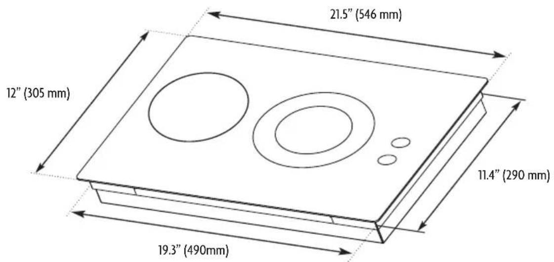

| Glass Width 12” (305 mm) | ||
| Glass Depth 21.5” (546 mm) | ||
| Cooktop Height Including Conduit (located at rear of cooktop, right side) | 3.15” (80 mm) | |
| Frame Width | 11.4” (290 mm) | |
| Frame Depth | 19.3” (490 mm) | |
| Cooktop Height 2” (52 mm) | ||
| Net Weight | 14.1 lbs. (6.4kg) | |
| Voltage Rating 240 V, 60 Hz | 120V, 60 Hz | |
| Power Rating 3000 W | 2600 W | |
PARTS AND FEATURES
Figure 2
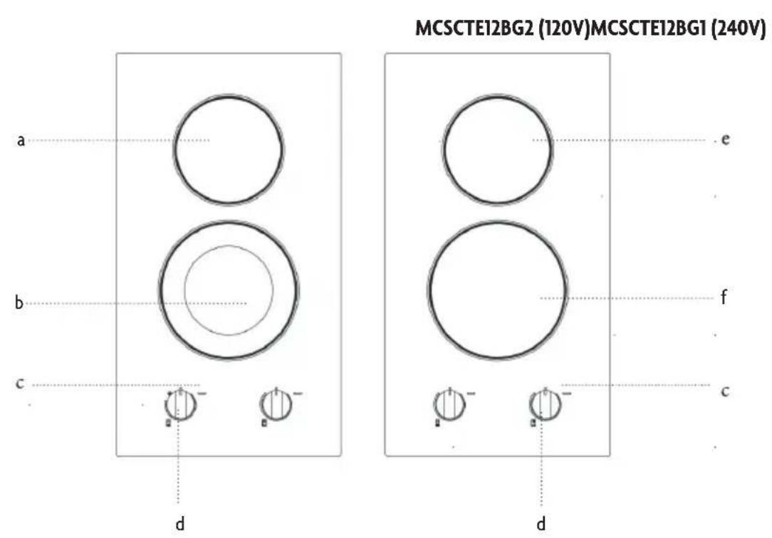
a. Single Cooking Zone
b. Single/Dual Cooking Zone
c. Hot Surface Indicator Light
d. Control Knobs
e. Single Cooking Zone
f. Single Cooking Zone
INSTALLATION REQUIREMENTS
TOOLS AND PARTS
Gather the required tools and parts before starting installation. Read and follow the instructions provided with any tools listed here.
Tools Required
- Tape Measure
• 1/4" (6.35 mm) Nut Driver
Marker or Pencil
- Pliers
• Flat-Blade Screwdriver
Parts Supplied
- Foam Strip Roll
- Clamping Brackets (4)
• 2-1/2" (6.4 cm) Clamping Screws (2)
Parts Required
• A UL Listed or CSA Approved Connector for 1/2" (1.3 cm) Diameter Conduit
• UL Listed Wire Connectors
Check local codes. Check existing electrical supply. (Refer to “Electrical Requirements” section on page 9.) It is recommended that all electrical connections be made by a licensed, qualified technician.
LOCATION REQUIREMENTS
▲ IMPORTANT: Observe all governing codes and ordinances. When installing cooktop, use minimum dimensions given.
- To eliminate the risk of burns or fire when reaching over the heated surface units, cabinet storage space located above the surface units SHOULD be avoided. If cabinet storage is to be provided, the risk can be reduced by installing a range hood that projects horizontally a minimum of 5" (12.7 cm) beyond the bottom of the cabinets.
- The cooktop SHOULD be a specified cooktop that is approved to be installed either alone or over an undercounter built-in oven. Check the cooktop base for an approved installation label. If you do not find this label, contact your dealer to confirm that your cooktop is approved.
• The cooktop SHOULD be installed in a level countertop. - Ovens approved for this type of installation will have an approval label located on the top of the oven. If you do not find this label, contact your dealer to confirm that your oven is approved. (Refer to oven manufacturer's Installation Instructions for approval for built-in undercounter use and proper cutout dimensions.)
- The cooktop SHOULD be installed away from strong draft areas, such as windows, doors, fans or strong heating vents. The cooktop SHOULD be located for convenient use in the kitchen.
- Use the countertop opening dimensions that are given with these Installation Instructions. Given dimensions are minimum clearances and provide 0" (0 cm) clearance.
• Grounded electrical supply is required. (Refer to “Electrical Requirements” section on page 9.)
LOCATION REQUIREMENTS
▲ IMPORTANT: If installing a range hood or microwave hood combination above the cooktop, follow the range hood or microwave hood combination installation instructions for dimensional clearances above the cooktop surface.
▲ NOTE: After making the countertop cutout, some installations may require notching down the base cabinet side walls to clear the cooktop base. To avoid this modification, use a base cabinet with sidewalls wider than the cutout.
a. Combustible area above countertop
b. Recommended upper cabinet width: 12' (30.5 cm)
c. Recommended upper cabinet depth: 13" (33 cm)
d. 30" (76.2 cm) minimum clearance between top of cooktop platform and bottom of uncovered wood or metal cabinet (24" [61 cm] minimum clearance if bottom of wood or metal cabinet is covered by not less than 1/4" [0.6 cm] flame retardant millboard covered with not less than No. 28 MSG sheet steel, 0.015" [0.04 cm] stainless steel, or 0.024" [0.06 cm] aluminum or 0.020" [0.05 cm] copper)
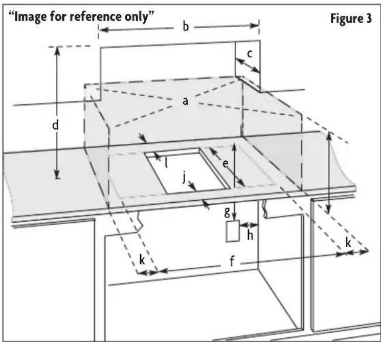
e. Recommended cutout depth: 19-1/4" (49.0 cm) The cooktop will fit in cutout from 19-1/8" to 19-5/16" (48.6 to 49.0 cm).
f. Recommended cutout width: 11.4" (29.0 cm) The cooktop will fit in cutout from 11.2" to 22-1/8" (28.4 to 29.0 cm)
g. Minimum distance from top of countertop to junction box or outlet: 7" (17.8 cm)
h. Maximum distance from right side of cabinet to junction box or outlet: 9" (23.0 cm).
i. Minimum clearance from upper cabinet to countertop within minimum horizontal clearances to cooktop: 18" (45.7 cm)
j. Minimum clearance between front edge and countertop: 2" (5.1 cm)
k. Minimum distance to nearest left and right side combustible surface above cooktop: 2" (5.1 cm)
- Minimum clearance between back wall and countertop: 2" (5.1 cm)
▲ NOTE: If cabinet has a drawer, a 5-1/2" (14.0 cm) depth clearance from the top of the countertop to the top of the drawer (or other obstruction) in base cabinet is required.
ELECTRICAL REQUIREMENTS
⚠ WARNING: Electrical Shock Hazard
• Disconnect power before servicing.
• Use 8 gauge copper wire.
• Electrically ground cooktop.
• Failure to follow these instructions can result in death, fire, or electrical shock.
If codes permit and a separate ground wire is used, it is recommended that a qualified technician determine that the ground path and wire gauge are in accordance with local codes.
Check with a qualified technician if you are not sure the cooktop is properly grounded.
Make sure that the electrical connection and wire size are adequate and in conformance with the National Electrical Code, ANSI/NFPA 70-latest edition or CSA Standards C22.1-94, Canadian Electrical Code, Part 1 and C22.2 No. O-M91-latest edition, and all local codes and ordinances.
Before You Make the Electrical Connection
To properly install your cooktop, you SHOULD determine the type of electrical connection you will be using and follow the instructions provided for it here.
- A 3-wire or 4-wire, single phase, 120/240 volt, 60-Hz., AC only electrical supply is required on a separate, 40-amp circuit fused on both sides of the line. The model/serial number rating plate is located on the metal cabinet underneath the cooktop.
• The cooktop is rated 120/240 volt. Some models have a neutral (white) wire. - The cooktop SHOULD be connected directly to the junction box through flexible, armored or nonmetallic sheathed, copper cable. The flexible, armored cable extending from the fuse box or circuit breaker box SHOULD be connected directly to the junction box.
- Locate the junction box to allow as much slack as possible between the junction box and the cooktop so that the cooktop can be moved if servicing becomes necessary in the future.
• DO NOT cut the conduit. Use the length of conduit provided.
• A UL listed or CSA approved conduit connector SHOULD be provided at each end of the power supply cable (at the cooktop and at the junction box). A listed conduit connector is already provided at the cooktop.
• If the house has aluminum wiring, follow the procedure below: - Connect a section of solid copper wire to the pigtail leads.
- Connect the aluminum wiring to the added section of copper wire using special connectors and/or tools designed and UL listed for joining copper to aluminum.
- Follow the electrical connector manufacturer's recommended procedure. Aluminum/copper connection SHOULD conform with local codes and industry accepted wiring practices.
INSTALLATION INSTRUCTIONS
PREPARING COOKTOP FOR INSTALLATION
WARNING: Excessive Weight Hazard
• Use two or more people to move and install cooktop.
• Failure to do so can result in back or other injury.
Decide on the final location for the cooktop. Avoid drilling into or severing existing wiring during installation.
-
Using 2 or more people, place the cooktop upside down on a covered surface using the foam end posts from the packaging. Make sure that the knobs are not resting on the foam.
-
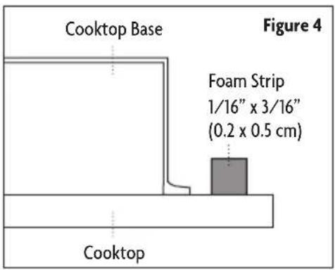
Remove foam strip roll from the package containing literature. Remove one strip at a time and apply foam strip adhesiveside down around bottom of the cooktop glass. (Refer to Figure 4.)
▲ NOTE: The foam strip helps avoid damage to the underside of the cooktop glass from debris and helps the cooktop sit flat on uneven counters.
INSTALLING COOKTOP
Type 1: Cooktop Over Undercounter Built-In Oven
Using 2 or more people, place cooktop right side up into the cutout.
▲ IMPORTANT: Clamping brackets SHOULD NOT be used.
▲ NOTE: Make sure that the front edge of the cooktop is parallel to the front edge of the countertop. If repositioning is needed, lift entire cooktop up from cutout to avoid scratching the countertop.
Type 2: Cooktop Over Cabinets
- Determine whether your cabinet construction provides clearance for installing clamping brackets at cooktop base ends. (Refer to figure 3 on page 9.)
- The clamping brackets SHOULD be installed after the cooktop is placed into the cutout. (Refer to Figure 5.)
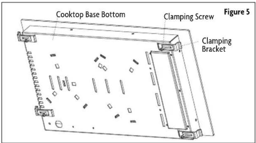
Installing Brackets After Placing Cooktop in Cutout
- Using 2 or more people, place the cooktop right side up into the cutout.
▲ NOTE: Make sure that the front edge of the cooktop is parallel to the front edge of the countertop. If repositioning is needed, lift entire cooktop up from cutout to avoid scratching the countertop. - Remove the selected brackets from the bottom of the cooktop base.
-
Select bracket mounting locations that will allow the bracket to extend far enough out from the cooktop for the installation of clamping screws. (Refer to Figure 6.)
-
Attach brackets to cooktop base bottom with bracket clamping screws using the bracket mounting holes. Securely tighten screws.
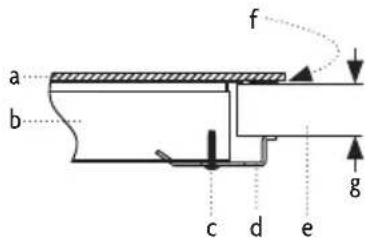
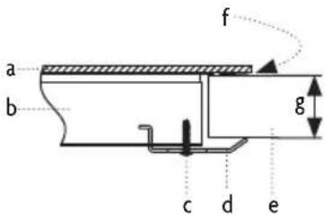
Option 1: Countertop is 1-1/8" (3cm) thick.
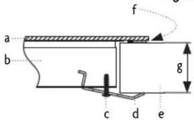
Option 2: Countertop is 1-9/16" (4cm) thick.
Option 3: Countertop is 2" (5cm) thick.
a. Cooktop
b. Cooktop Base
c. Clamping Screw
d. Clamping Bracket (It extends far enough beyond cooktop base to allow installation of clamping screws.)
e. Countertop
f. Foam Seal
g. Thickness of the Countertop
MAKE ELECTRICAL CONNECTION
⚠ WARNING: Electrical Shock Hazard
• Disconnect power before servicing.
• Use 8 gauge copper wire.
• Electrically ground cooktop.
• Failure to follow these instructions can result in death, fire, or electrical shock.
This cooktop is manufactured with a frame connected, green or bare ground wire. Connect the cooktop cable to the junction box through the UL listed or CSA approved conduit connector.
Electrical Connection Options
| If your home has And you will be connecting to Go to Section | ||
4-wire direct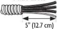 | A fused disconnect or circuit breaker box | 4-Wire Cable from Power Supplyto 3-Wire Cable from Cooktop (page 13) |
3-wire direct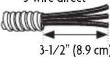 | A fused disconnect or circuit breaker box | 3-Wire Cable from Power Supplyto 3-Wire Cable from Cooktop (page 13) |
4-Wire Cable from Power Supply to 3-Wire Cable from Cooktop (Refer to Figure 7.)
▲ IMPORTANT: Use the 4-wire cable from power supply where local codes do not permit connecting the frame-ground conductor to the neutral (white) junction box wire.
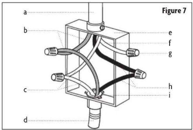
a. 4-Wire Cable from Power Supply
b. Red Wires
c. Green or Bare Ground Wire (from Cooktop)
d. 3-Wire Cable from Cooktop
e. Junction Box
f. White Wire (from Power Supply)
g. UL Listed Wire Connector
h. Black Wires
i. UL Listed or CSA Approved Conduit Connector
-
Disconnect power
-
Remove junction box cover if present.
-
Connect the flexible cable conduit from the cooktop to the junction box using a UL listed or CSA approved conduit connector.
-
Tighten screws on conduit connector, if present.
-
Connect the two black wires together using the UL listed wire connectors.
-
Connect the two red wires together using the UL listed wire connectors.
-
Connect the green or bare ground wire from the cooktop cable to the green or bare ground wire (in the junction box) using the UL listed wire connectors.
-
Put a UL listed wire connector on the end of the white wire.
▲ NOTE: DO NOT connect the bare ground wire to the neutral (white) wire in the junction box.
-
Install junction box cover.
-
Reconnect power.
3-Wire Cable from Power Supply to 3-Wire Cable from Cooktop (Refer to Figure 8.)
▲ IMPORTANT: Use the 3-wire cable from power supply where local codes permit connecting the frame-ground conductor to the neutral (white) junction box wire.
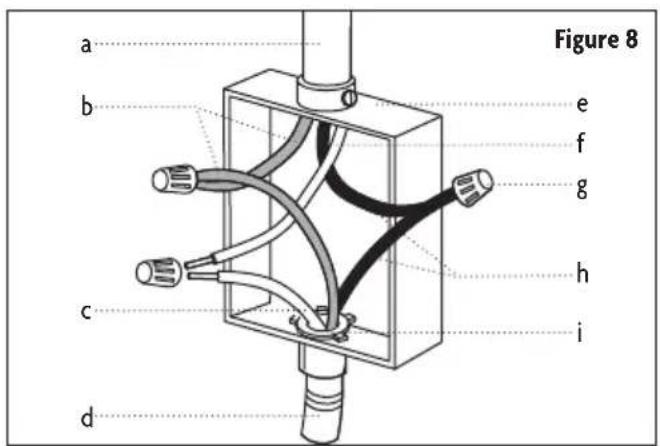
a. 3-Wire Cable from Power Supply
b. Red Wires
c. Green or Bare Ground Wire (from Cooktop)
d. 3-Wire Cable from Cooktop
e. Junction Box
f. White Wire (from Power Supply)
g. UL Listed Wire Connector
h. Black Wires
i. UL Listed or CSA Approved Conduit Connector
-
Disconnect power
-
Remove junction box cover, if present.
-
Connect the flexible cable conduit from the cooktop to the junction box using a UL listed or CSA approved conduit connector.
- Tighten screws on conduit connector if present.
- Connect the two black wires together using the UL listed wire connectors.
- Connect the two red wires together using the UL listed wire connectors.
- Connect the green or bare cooktop cable wires to the white (neutral) wire in the junction box using the UL listed wire connectors.
- Install junction box cover.
- Reconnect power.
Complete Installation
- Check that all parts are now installed. If there is an extra part, go back through the steps to see which step was skipped.
- Check that you have all your tools.
- Dispose of/recycle all packaging materials.
- Use a mild solution of liquid household cleaner and warm water to clean cooktop before use. Dry thoroughly with a soft cloth. (For more information, refer to “Care and Maintenance” section on page 19.)
- Read the "Operation Instruction" section on page 17.
- Reconnect power.
NOTE: If the cooktop does not work after turning on the power, check that a circuit breaker has not tripped or a household fuse has not blown. (Refer to “Troubleshooting” section on page 20.)
BEFORE USE
CERAMIC GLASS SURFACE
The surface cooking area will glow red when an element is on. However some parts of the surface cooking area may not glow red when an element is on. This is normal operation. The burner will cycle on and off to maintain the selected heat level and to keep to keep the cooktop from reaching extreme temperatures.
It is normal for the surface of light colored ceramic glass to appear to change color when surface cooking areas are hot. As the glass cools, it will return to its original color.
Cleaning off the cooktop before and after each use will help keep it free from stains and provide the most even heating. On cooktops with light colored ceramic glass, soils and stains may be more visible, and may require more cleaning and attention. Cooktop cleaner and a cooktop scraper are recommended. (For more information, refer to “Care and Maintenance” section on page 19.)
- Avoid storing jars or cans above the cooktop. Dropping a heavy or hard object onto the cooktop could crack the cooktop.
- DO NOT leave a hot lid on the cooktop. As the cooktop cools, air can become trapped between the lid and the cooktop, and the ceramic glass could break when the lid is removed.
- Clean up all spills and soils as soon as possible. Allow the cooktop to cool down slightly. Then, while wearing oven mitts, remove the spills using a scraper while the surface is still warm. If sugary spills are allowed to cool down, they can adhere to the cooktop and can cause pitting and permanent marks.
• DO NOT slide cookware or bakeware across the cooktop. Aluminum or copper bottoms and rough finishes on cookware or bakeware could leave scratches or marks on the cooktop. - DO NOT cook popcorn in prepackaged aluminum containers on the cooktop. They could leave aluminum marks that cannot be removed completely.
- DO NOT allow objects that could melt, such as plastic or aluminum foil, to touch any part of the entire cooktop.
• DO NOT use the cooktop as a cutting board.
• DO NOT cook foods directly on the cooktop. - Use flat-bottomed cookware for best heat conduction and energy efficiency. Cookware with rounded, warped, ribbed or dented bottoms could cause uneven heating and poor cooking results.
- Determine flatness by placing the straight edge of a ruler across the bottom of the cookware. While you rotate the ruler, no space or light SHOULD be visible between it and the cookware.
• Cookware designed with slightly indented bottoms or small expansion channels can be used.
• Make sure the bottoms of pots and pans are clean and dry before using them. Residue and water can leave deposits when heated.
- Use cookware about the same size as the surface cooking area. Cookware SHOULD NOT extend more than 1/2" (1.3 cm) outside the area.
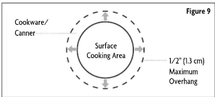
COOKWARE
▲ IMPORTANT: DO NOT leave empty cookware on a hot surface cooking area, element or surface burner.
Ideal cookware SHOULD have a flat bottom, straight sides, and a well-fitting lid and the material SHOULD be of medium-to-heavy thickness. Rough finishes may scratch the cooktop. Aluminum and copper may be used as a core or base in cookware. However, when used as a base they can leave permanent marks on the cooktop or grates.
Cookware material is a factor in how quickly and evenly heat is transferred, which affects cooking results. A nonstick finish has the same characteristics as its base material. For example, aluminum cookware with a nonstick finish will take on the properties of aluminum.
Use the following chart as a guide for cookware material characteristics.
| Cookware Characteristics | |
| Aluminum | Heats quickly and evenly.Suitable for all types of cooking.Medium or heavy thickness is best for most cooking tasks. |
| Cast iron | Heats slowly and evenly.Good for browning and frying.Maintains heat for slow cooking. |
| Ceramic or Ceramic glass | Heats slowly, but unevenly.Ideal results on low to medium heat settings.Follow manufacturer's instructions. |
| Copper Heats very quickly and evenly. | |
| Earthenware | Use on low heat settings.Follow manufacturer's instructions. |
| Porcelain enamel-onsteel or cast iron Refer to stainless steel or cast iron. | |
| Stainless steel | Heats quickly, but unevenly.A core or base of aluminum or copper on stainless steel provides even heating. |
HOME CANNING
When canning for long periods, alternate the use of surface cooking areas, elements or surface burners between batches. This allows time for the most recently used areas to cool.
- Center the canner on the grate or largest surface cooking area or element. On electric cooktops, canners SHOULD NOT extend more than 1/2" (1.3 cm) beyond the surface cooking area or element.
• DO NOT place canner on 2 surface cooking areas, elements or surface burners at the same time.
• On ceramic glass models, use only flat-bottomed canners. - On coil element models, the installation of a Canning Unit Kit is recommended. If a kit is not installed, the life of the coil element will be shortened.
- For more information, contact your local agricultural department. Companies that manufacture home canning products can also offer assistance.
OPERATION INSTRUCTIONS
COOKTOP CONTROLS
WARNING: Fire Hazard
• Turn off all controls when done cooking.
• Failure to do so can result in death or fire.
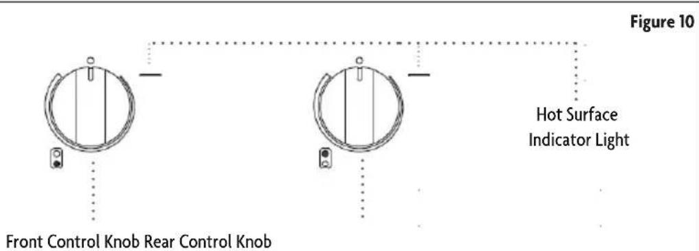
The control knobs can be set to anywhere between HIGH and LOW. Push in and turn to setting. The surface cooking area locator shows which element is turned on. (Refer to Figure 11 and the chart on the right for setting heat levels.)
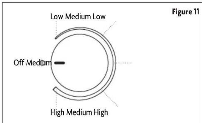
| Setting Recommended Use | |
| Low | Keep food warm.Melt chocolate or butter.Low simmer using lids. |
| Medium Low | Stew or steam food.Simmer. |
| Medium | Maintain a slow boil.Fry or saute foods.Cook soups, sauces and gravies.High simmer or simmer without lids. |
| Medium High | Hold a rapid boil.Quickly brown or sear food. |
| High | Start food cooking.Bring liquid to a boil. |
| Dual Zone Element | Home canning.Large-diameter cookware.Large quantities of food. |
Dual Zone Element
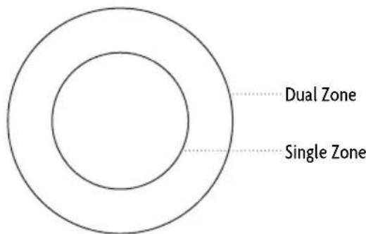
The dual zone elements offer flexibility depending on the size of the cookware. Single zone can be used in the same way as a regular element. The dual zone combine single and dual heating elements and are recommended for larger cookware, large quantities of food, and home canning.
For best High heat performance, match the cookware size to the size of heating element.
For best Low heat or Simmer performance, match the cookware size to the dual zone heating element and operate single zone heating element.
Figure 12
To Use SINGLE:
-
Push in and turn knob from the OFF position to the SINGLE zone anywhere between LOW and HIGH.
-
Turn knob to OFF position when finished.
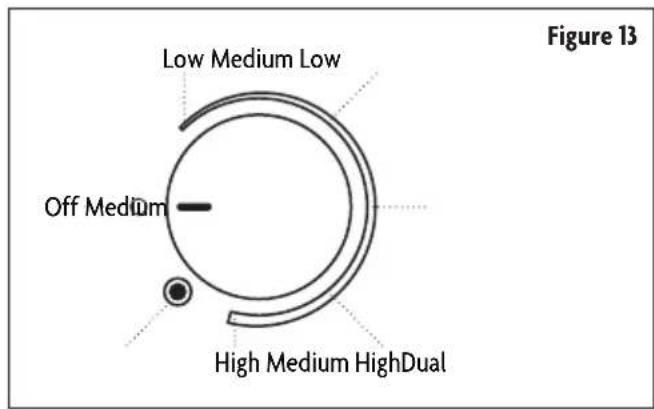
To Use DUAL:
-
Push in and turn knob from the OFF position to the DUAL position.
-
Turn knob to OFF when finished.
Hot Surface Indicator Light
This unit features a Hot Surface Indicator Light. The Hot Surface Indicator Light will glow as long as any surface cooking area is too hot to touch, even after the surface cooking area(s) is turned off.
CARE AND MAINTENANCE
⚠ WARNING: Before cleaning, make sure all controls are off and the oven and cooktop are cool. ALWAYS follow label instructions on cleaning products.
Use soap, water and a soft cloth or sponge unless otherwise noted.
CLEANING COOKTOP CONTROLS
To avoid damage to the cooktop controls, DO NOT use steel wool, abrasive cleansers or oven cleaner.
To avoid damage, DO NOT soak knobs.
When replacing knobs, make sure knobs are in the Off position.
DO NOT remove seals under knobs.
- Soap and water: Pull knobs straight away from control panel to remove.
• Dishwasher: Pull knobs straight away from control panel to remove.
CLEANING CERAMIC GLASS
To avoid damage to the cooktop, DO NOT use steel wool, abrasive powder cleansers, chlorine bleach, rust remover or ammonia.
Always wipe with a clean, wet cloth or sponge and dry thoroughly to avoid streaking and staining.
Light to Moderate Soil
• Paper towels or clean damp sponge.
Sugary Spills (Jellies, Candy, Syrup)
• Cooktop Scraper: Clean while the cooktop is still warm. You may want to wear oven mitts while doing so.
• Cooktop Polishing Creme and clean damp paper towel: Clean as soon as cooktop has cooled down. Rub creme into surface with a damp paper towel or soft cloth. Continue rubbing until white film disappears.
Heavy Soil, Dark Streaks, Specks and Discoloration
• Cooktop Polishing Creme or nonabrasive cleanser: Rub product into soil with a damp paper towel or soft cloth. Continue rubbing until white film disappears.
Burned-On Soil
• Cooktop Polishing Creme and Cooktop Scraper: Rub creme into soil with damp paper towel. Hold scraper as flat as possible on surface and scrape. Repeat for stubborn spots. Polish entire cooktop with creme and paper towel.
Metal Marks from Aluminum and Copper
• Cooktop Polishing Creme: Clean as soon as cooktop has cooled down. Rub creme into surface with a damp paper towel or soft cloth. Continue rubbing until white film disappears. The marks will not totally disappear but after many cleanings become less noticeable.
Tiny Scratches and Abrasions
• Cooktop Polishing Creme: Rub creme into surface with a damp paper towel or soft cloth. Continue rubbing until white film disappears. Scratches and abrasions do not affect cooking performance and after many cleanings become less noticeable.
TROUBLESHOOTING
Try the solutions suggested here first in order to avoid the cost of an unnecessary service call.
| Problem Possible Causes Solutions | ||
| Nothing will operate | Has a household fuse blown, or has a circuit breaker tripped? | Replace the fuse or reset the circuit breaker. If the problem continues, call an electrician. |
| Is the cooktop wired properly? Refer to “Installation Instructions” on page 11. | ||
| Cooktop will not operate Is the control knob set correctly? Push in knob before turning to a setting. | ||
| Excessive heat around cookware on cooktop | Is the cookware the proper size? | Use cookware about the same size as the surface cooking area, element or surface burner. Cookware SHOULD NOT extend more than 1/2” (1.3 cm) outside the cooking area. |
| Cooktop cooking results not what expected | Is the proper cookware being used? Refer to “Cookware” section on page 16. | |
| Is the control knob set to the proper heat level? | Refer to “Cooktop Controls” section on page 17. | |
| Is the cooktop level? | Level the cooktop. Refer to “Installation Instructions” on page 11. | |
| A vapor is being emitted from the knobs of the cooktop | Is the cooktop in its first use(s)? | During the first use(s), a vapor may be seen exiting the holes around the knobs of the cooktop. This is normal and SHOULD disappear after use. |

LIMITED WARRANTY
MC Appliance Corporation warrants each new Electric Cooktop to be free from defects in material and workmanship, and agrees to remedy any such defect or to furnish a new part(s), at the company's option, for any part(s) of the unit that has failed during the warranty period. Parts and labor expenses are covered on this unit for a period of one year from the date of purchase. A copy of the dated sales receipt/invoice is required to receive warranty service, replacement or refund.
This warranty covers appliances in use within the contiguous United States, Alaska, Hawaii and Puerto Rico. This warranty does not cover the following:
• Damages due to shipping damage or improper installation.
• Damages due to misuse or abuse.
• Content losses due to failure of the unit.
• Repairs performed by unauthorized service agents.
• Service calls that do not involve defects in material and workmanship such as instructions on proper use of the product or improper installation.
• Replacement or resetting of house fuses or circuit breakers.
• Failure of this product if used for other purposes than its intended purpose.
• Disposal costs for any failed unit not returned to our factory.
• Any delivery/installation costs incurred as the result of a unit that fails to perform as specified.
• Expenses for travel and transportation for product service if your appliance is located in a remote area where service by an authorized service technician is not available.
- The removal and reinstallation of your appliance if it is installed in an inaccessible location or is not installed in accordance with published installation instructions.
• Refunds for non repairable products are limited to the price paid for the unit per the sales receipt.
- This warranty is non transferable. This warranty applies only to the original purchaser and does not extend to any subsequent owner(s).
Limitations of Remedies and Exclusions:
Product repair in accordance with the terms herein, is your sole and exclusive remedy under this limited warranty. Any and all implied warranties including merchantability and fitness for a particular purpose are hereby limited to one year or the shortest period allowed by law. MC Appliance Corporation is not liable for incidental or consequential damages and no representative or person is authorized to assume for us any other liability in connection with the sale of this product. Under no circumstances is the consumer permitted to return this unit to the factory without the prior written consent of MC Appliance Corporation.
Some states prohibit the exclusion or limitation of incidental or consequential damages, or limitations on implied warranties. This warranty gives you specific legal rights, and you may also have other rights which vary from state to state.
Model
Parts
Labor
Type of Service
MCSCTE12BG1 & MCSCTE12BGOne Year
One Year
Carry In
For Service or Assistance please call 888-775-0202 or visit us on the web at www.mcappliance.com to request warranty service or order parts.

CNA International, Inc. d/b/a MC Appliance Corporation. All rights reserved. Magic Chef® logo is a registered trademark of CNA International, Inc.
www.mcappliance.com Printed in China

natural_image
Two identical diagrams showing circular components with control knobs, no text or symbols presentModelo MCSCTE12BG1
MCSCTE12BG2
PLEASE READ THIS MANUAL CAREFULLY BEFORE USING YOUR ELECTRIC RANGE AND KEEP IT FOR FUTURE REFERENCE.

- 12-Inch Electric Cooktop
- PRODUCT REGISTRATION
- CONTENTS
- PRECAUTIONS
- EXPLANATION OF SYMBOLS
- WARNING
- CAUTION
- THIS PRODUCT IS INTENDED FOR HOUSEHOLD USE ONLY
- IMPORTANT SAFETY INSTRUCTIONS
- SAVE THESE INSTRUCTIONS FOR FUTURE REFERENCE
- SPECIFICATIONS
- PARTS AND FEATURES
- INSTALLATION REQUIREMENTS
- TOOLS AND PARTS
- Tools Required
- Parts Supplied
- Parts Required
- LOCATION REQUIREMENTS
- ELECTRICAL REQUIREMENTS
- ⚠ WARNING: Electrical Shock Hazard
- Before You Make the Electrical Connection
- INSTALLATION INSTRUCTIONS
- PREPARING COOKTOP FOR INSTALLATION
- WARNING: Excessive Weight Hazard
- INSTALLING COOKTOP
- Type 2: Cooktop Over Cabinets
- Installing Brackets After Placing Cooktop in Cutout
- MAKE ELECTRICAL CONNECTION
- Complete Installation
- BEFORE USE
- CERAMIC GLASS SURFACE
- COOKWARE
- HOME CANNING
- OPERATION INSTRUCTIONS
- COOKTOP CONTROLS
- WARNING: Fire Hazard
- Dual Zone Element
- To Use SINGLE:
- To Use DUAL:
- Hot Surface Indicator Light
- CARE AND MAINTENANCE
- CLEANING COOKTOP CONTROLS
- CLEANING CERAMIC GLASS
- Light to Moderate Soil
- Sugary Spills (Jellies, Candy, Syrup)
- Heavy Soil, Dark Streaks, Specks and Discoloration
- Burned-On Soil
- Metal Marks from Aluminum and Copper
- Tiny Scratches and Abrasions
- TROUBLESHOOTING
- LIMITED WARRANTY
- Limitations of Remedies and Exclusions:
Brand : Magic Chef
Model : MCSCTE12BG1
Category : Cooker