
MC257 - Audio Receiver MCINTOSH - Free user manual and instructions
Find the device manual for free MC257 MCINTOSH in PDF.


| Product Type | Audio Receiver (Multichannel Amplifier) |
| Brand | McIntosh |
| Model | MC257 |
| Dimensions (W x H x D) | 17.5 in (44.5 cm) x 7.5 in (19.0 cm) x 19.0 in (48.3 cm) |
| Weight | 75 lbs (34 kg) |
| Power Output | 200 watts per channel into 2, 4, or 8 ohms (all channels driven) |
| Number of Channels | 5 |
| Total Harmonic Distortion | 0.005% or less |
| Frequency Response | 20 Hz – 20 kHz (+0, -0.25 dB) |
| Signal-to-Noise Ratio | 120 dB |
| Input Sensitivity | 2.5 V (balanced), 1.4 V (unbalanced) |
| Input Impedance | 20 k ohms (balanced), 10 k ohms (unbalanced) |
| Power Consumption | 1000 watts (maximum) |
| Standby Power | < 0.5 watts |
| Inputs | 5 pairs of balanced (XLR) and unbalanced (RCA) stereo inputs |
| Outputs | 5 pairs of binding post speaker terminals (gold-plated) |
| Trigger Input/Output | 12 V DC trigger input and output (3.5 mm mono jack) |
| Cooling | McIntosh patented Heat Sink with Sentry Monitor (thermal protection) |
| Construction | Stainless steel chassis, glass front panel with blue meters |
| Cleaning Instructions | Wipe with a soft, dry cloth. Do not use solvents or abrasive cleaners. |
| Safety Features | Sentinel Monitor circuit protects against short circuits and overheating. |
| Spare Parts Availability | Authorized service centers; contact McIntosh for parts and repairs. |
| Warranty | 3 years (parts and labor) |
Frequently Asked Questions - MC257 MCINTOSH
User questions about MC257 MCINTOSH
0 question about this device. Answer the ones you know or ask your own.
Ask a new question about this device
Download the instructions for your Audio Receiver in PDF format for free! Find your manual MC257 - MCINTOSH and take your electronic device back in hand. On this page are published all the documents necessary for the use of your device. MC257 by MCINTOSH.
USER MANUAL MC257 MCINTOSH
McIntosh Laboratory, Inc. 2 Chambers Street Binghamton, New York 13903-2699 Phone: 607-723-3512 www.mcintoshlabs.com

Important Safety Information is supplied in a separate document “Important Additional Operation Information Guide”
Thank You
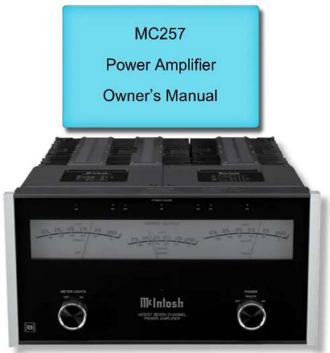
Your decision to own this McIntosh MC257 Seven Channel Power Amplifier ranks you at the very top among discriminating music listeners. You now have "The Best." The McIntosh dedication to "Quality," is assurance that you will receive many years of musical enjoyment from this unit. Please take a short time to read the information in this manual. We want you to be as familiar as possible with all the features and functions of your new McIntosh.
Please Take A Moment
The serial number, purchase date and McIntosh Dealer name are important to you for possible insurance claim or future service. The spaces below have been provided for you to record that information:
Serial Number:
Purchase Date:
Dealer Name:
Technical Assistance
If at any time you have questions about your McIntosh product, contact your McIntosh Dealer who is familiar with your McIntosh equipment and any other brands that may be part of your system. If you or your Dealer wish additional help concerning a suspected problem, you can receive technical assistance for all McIntosh products at:
McIntosh Laboratory, Inc.
2 Chambers Street
Binghamton, New York 13903
Phone: 607-723-3512
Fax: 607-724-0549
Customer Service
If it is determined that your McIntosh product is in need of repair, you can return it to your Dealer. You can also return it to the McIntosh Laboratory Service Department. For assistance on factory repair return procedure, contact the McIntosh Service Department at:
McIntosh Laboratory, Inc.
2 Chambers Street
Binghamton, New York 13903
Phone: 607-723-3515
Fax: 607-723-1917
Table of Contents
Safety Instructions....2
(Separate Sheet) .... Important Additional Operation Information Guide
Thank You and Please Take a Moment....2
Technical Assistance and Customer Service....2
Table of Contents 2
General Information 2
Connector and Cable Information ....3
Introduction....3
Performance Features .... 3
Dimensions 4
Installation 5
Rear Panel Connections and Switch....6
Output Terminals and How to Connect....7-8
Connection Diagram (Separate Sheets) ....Mc1A-3A
Front Panel Displays and Controls....10
How to Operate....11
Technical Description....12-15
Photos....16-17
Specifications....18
Packing Instruction....19
General Information
- For additional connection information, refer to the owner's manual(s) for any component(s) connected to the MC257.
- The MC257 mutes the speaker output for approximately two seconds when first turned on.
- For the best performance and safety it is important to always match the impedance of the Loudspeaker to the Power Amplifier connections. Refer to "How to Connect" pages 7 and 8.
Note: The impedance of a Loudspeaker actually varies as the Loudspeaker reproduces different frequencies. As a result, the nominal impedance rating of the Loudspeaker (usually measured at a midrange frequency) might not always agree with the impedance of the Loudspeaker at low frequencies where the greatest amount of power is required. Contact the Loudspeaker Manufacturer for additional information about the actual impedance of the Loudspeaker before connecting it to the McIntosh MC257.
- In the event the MC257 over heats, due to improper ventilation and/or high ambient temperature, the protection circuits will activate. The Front Panel Power Guard LED will continuously indicate ON and the audio will be muted. When the MC257 has returned to a safe operating temperature, normal operation will resume.
- When discarding the unit, comply with local rules
or regulations. Batteries should never be thrown away or incinerated but disposed of in accordance with the local regulations concerning battery disposal.
- For additional information on the MC257 and other McIntosh Products please visit the McIntosh Website at www.mcintoshlabs.com.

Copyright 2019 © by McIntosh Laboratory, Inc.
Connector and Cable Information
XLR Connectors
The MC257 has different Pin Configurations for the Input and Output XLR Connectors, refer to the following connections:
PIN 1: Shield/Ground
PIN 2: + Input/Output
PIN 3: - Input/Output

Power Control Connector
The MC257 Power Control Input receives an On/Off signal from +5 to +12 volts. The Power Control Output
will in turn provide a +12 volt Output Signal with a total current up to 50mA. An additional connection is for controlling the illumination of the MC257 Power Output Meters. The 1/8 inch stereo mini phone plug connects to a McIntosh Preamplifier or A/V Control Center Power Control Output.

Output Terminal Connector
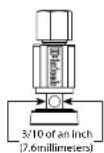
When cables with spade lugs are used for Loudspeaker Connection, the spade lugs need an opening of at least 3/10 inch (7.6mm).
Introduction
Now you can take advantage of traditional McIntosh standards of excellence in the MC257 Power Amplifier. This Seven Channel Amplifier with high current output will drive any set of high quality Loudspeakers. The MC257 reproduction is sonically transparent and absolutely accurate. The McIntosh Sound is “The Sound of the Music Itself.”
Performance Features
- Power Output
The MC257 is a Seven Channel Power Amplifier with a capability of 250 Watts from the Front Three Channels (Left, Center & Right) and 160 Watts from the Surround Channels into speakers with less than 0.005% distortion. The Power Amplifier Circuitry uses ThermalTrak ^4 Output Transistors for lower distortion and cool operation.
• Balanced and Unbalanced Inputs
Balanced connections guard against induced noise and allow long cable runs without compromising sound quality.
- Power Guard
The patented McIntosh Power Guard circuit prevents the amplifier from being over driven into clipping, with its harsh distorted sound that can also damage your valuable loudspeakers.
- Zone B Operation
The Zone B on the MC257 provides Two Channel Music Playback in a second room with 160 watts per channel, while at the time Zone A provides Five Channel Home Theater Playback.
- Sentry Monitor and Thermal Protection
McIntosh Sentry Monitor power output stage protection circuits ensure the MC257 will have a long and trouble free operating life. Built-in Thermal Protection Circuits guard against overheating.
^1 ThermalTrak ^™ and ON Semiconductor are trademarks of Semiconductor Components Industries, LLC
• Special Power Supply
A very large Power Transformer and Large Capacitors ensure stable noise free operation even though the power line varies.
- Illuminated Power Meters
The Illuminated Power Output Watt Meters on the MC257 are peak responding, and indicate the true power output of the amplifier. The Front Panel Meter Illumination may be switched Off at any time.
• McIntosh Custom Binding Posts
McIntosh patent pending gold plated output terminals deliver high current output. They accept large diameter wire and spade lugs. Banana plugs may also be used only in the United States and Canada.
- Glass Front Panel and Super Mirror Chassis Finish
The famous McIntosh Illuminated Glass Front Panel uses long life Light Emitting Diodes (LEDs) and the Stainless Steel Chassis with Super Mirror Finish ensures the pristine beauty of the MC257 will be retained for many years.
Dimensions
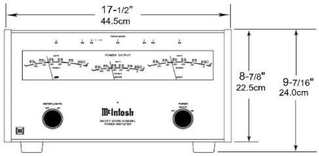
The following dimensions can assist in determining the best location for your MC257.
Front View of the MC257
Rear View of the MC257

Side View of the MC257

Installation
The MC257 can be placed upright on a table or shelf, standing on its four feet. It also can be custom installed in a piece of furniture or cabinet of your choice. The four feet may be removed from the bottom of the MC257 when it is custom installed as outlined below. The four feet together with the mounting screws should be retained for possible future use if the MC257 is removed from the custom installation and used free standing. The required panel cutout, ventilation cutout and unit dimensions are shown.
Always provide adequate ventilation for your MC257. Cool operation ensures the longest possible operating life for any electronic instrument. Do not install the MC257 directly above a heat generating component such as a high powered amplifier. If all the components are installed in a single cabinet, a quiet running ventilation fan can be a definite asset in maintaining all the system components at the coolest possible operating temperature.
A custom cabinet installation should provide the following minimum spacing dimensions for cool operation.
Allow at least 6 inches (15.24cm) above the top, 2 inches (5.08cm) below the bottom, 3 inches (7.62cm) behind the rear panel and 2 inches (5.08cm) on each side of the Power Amplifier, so that airflow is not obstructed. Allow 7/8 inch (2.22cm) in front of the mounting ^1 panel for clearance. Be sure to cut out a ventilation hole in the mounting shelf according to the dimensions in the drawing.
^1 When the MC257 is installed together with other McIntosh Components, check clearances on all components before proceeding.


Output Terminals
When connecting the Loudspeaker Hookup Cables to the MC257 Power Amplifier Output Terminals please follow the steps below:
- Rotate the top of the Output Te terclockwise until an opening appears. Refer to figures A and B.
- Insert the Loudspeaker hookup cable into the Output Terminal Post opening or the cable spade lug around the center post of the Output Terminal. Refer to figure C.
- Rotate the top of the Output Terminal Post clockwise until it is finger tight. Refer to figure D.
- Place the supplied McIntosh Wrench over the top of the Output Terminal and rotate it one quarter of a turn (90°) to secure the Loudspeaker Cable Connection. Do not over tighten, Refer to figure E.


Figure C Figure D

Figure E
How to Connect
Caution: Do not connect the AC Power Cord to the MC257 Rear Panel until after the Loudspeaker Connections are made. Failure to observe this could result in Electric Shock.
The connection instructions below, together with the MC257 Connection Diagram located on the separate folded sheets "Mc1A, Mc2A and Mc3A", are examples of a typical audio systems. Your system may vary from this, however the actual components would be connected in a similar manner. For additional information refer to "Connector and Cable Information" on page 3.
- For Zone A Operation, connect a power control cable from the Audio Preamplifier or A/V Control Center Power Control (Trigger) Output 1 to the MC257 POWER CONTROL ZA INPUT.
- For Zone B Operation, connect a power control cable from the Audio Preamplifier or A/V Control Center Power Control (Trigger) Output 2 to the MC257 POWER CONTROL ZB INPUT.
Notes: 1. When a Power Control Cable is connected between the MC257 and a Preamplifier (or A/V Control Center), the AUTO OFF Feature is bypassed. Refer to page 11.
-
When a Subwoofer Loudspeakers is being used together with the MC257, connect a Power Control Cable from the MC257 POWER CONTROL Output ZA or ZB to the Power Control Input on the Subwoofer Loudspeaker.
-
The MC257 has connections for Balanced Audio XLR Connection Cables that come from the connections on the Audio Preamplifier or A/V Control Center. Refer to the Connections on the separate folded sheets "Mc1A, Mc2A and Mc3A". UnBalanced Audio Cables can be used instead of the Balanced XLR cables.
The MC257 Power Amplifier is designed for Loudspeakers with an impedance of 4 ohms or 8 ohms. Connect a single Loudspeaker to each of the Output Ter minals.
When connecting Loudspeakers to the MC257 it is very important to use cables of adequate size, so there is little to no power loss in the cables. The size is specified in Gauge Numbers or AWG (American Wire Gauge). The smaller the Gauge number, the larger the wire size:
| Loudspeaker Cable Distance vs Wire Gauge Guide | |||
| Loudspeaker Impedance | 25 feet (7.62 meters) or less | 50 feet (15.24 meters) or less | 100 feet (30.48 meters) or less |
| 4 Ohms | 14AWG 12AWG 10AWG | ||
| 8 Ohms | 16AWG 14AWG 12AWG | ||
- Prepare the Loudspeaker Hookup Cable for attachment to the MC257 Power Amplifier:
Bare wire cable ends:
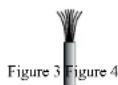
Carefully remove sufficient insulation from the cable ends, refer to figures 2, 3 & 4. If the cable is stranded, carefully twist the strands together
as tightly as possible.


Notes: 1. If desired, the twisted ends can be tinned with solder to keep the strands together.
2. The prepared bare wire cable ends may be inserted into spade lug connectors.
3. Banana plugs are for use in the United States and Canada only.
Banana Plugs are for use in the United States and Canada only:
- Attach the previously prepared bare wire cable ends into the banana plugs and secure the connections. Refer to figure F.
- Rotate the top of the Output Terminal Post clockwise until it is finger tight. Refer to figure G. Then using the McIntosh Wrench, rotate the top of the Output Terminal one quarter of a turn (90°). Do not over tighten. Refer to figure E.


- Referring to figure H, connect the Loudspeaker
hookup cables with banana plugs into the MC257 hole at the top of the terminal to the (⊖) Negative Output
Terminal and the (⊕) Positive Output Terminal identified as 4Ω (ohms) or 8Ω (ohms) connection to match the impedance of the Loudspeaker, being careful to observe the correct polarities. Place the LOAD Switch on the rear panel of the MC257 to either the 4 or 8 Ohm Setting, to match the impedance of the majority of the loudspeakers connected. If the Loudspeaker's impedance is in-between the available connections, use the nearest lower impedance connection. Refer to "General Information" Note 3 on page 2 for additional information.
WARNING: Loudspeaker terminals are hazardous live and present a risk of electric shock. For additional instruction on making Loudspeaker Connections contact your McIntosh Dealer or McIntosh Technical Support.
- Connect the MC257 power cord to an active AC outlet.
Spade Lug or Wire Connections:
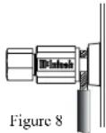
- Connect the Loudspeaker hookup cables to the MC257 COM (Negative) Output Terminal and Positive Output Terminal identified as 4Ω (ohms) or 8Ω (ohms) connection to match the impedance of the Loudspeaker, being careful to observe the correct polarities. Insert the spade lug connector or prepared section of the cable end into the terminal side access hole, and tighten the terminal cap until the cable is firmly clamped into the terminals so

the lugs or wire cannot slip out. Refer to figures 7 and 8.

If the Loudspeaker's impedance is in-between the available connections, use the nearest lower impedance connection. Refer to "General Information" Note 3 on page 2 for additional information.
WARNING: Loudspeaker terminals are hazardous live and present a risk of electric shock. For additional instruction on making Loudspeaker Connections contact your McIntosh Dealer or McIntosh Technical Support.
- Connect the MC257 power cord to an active AC outlet.

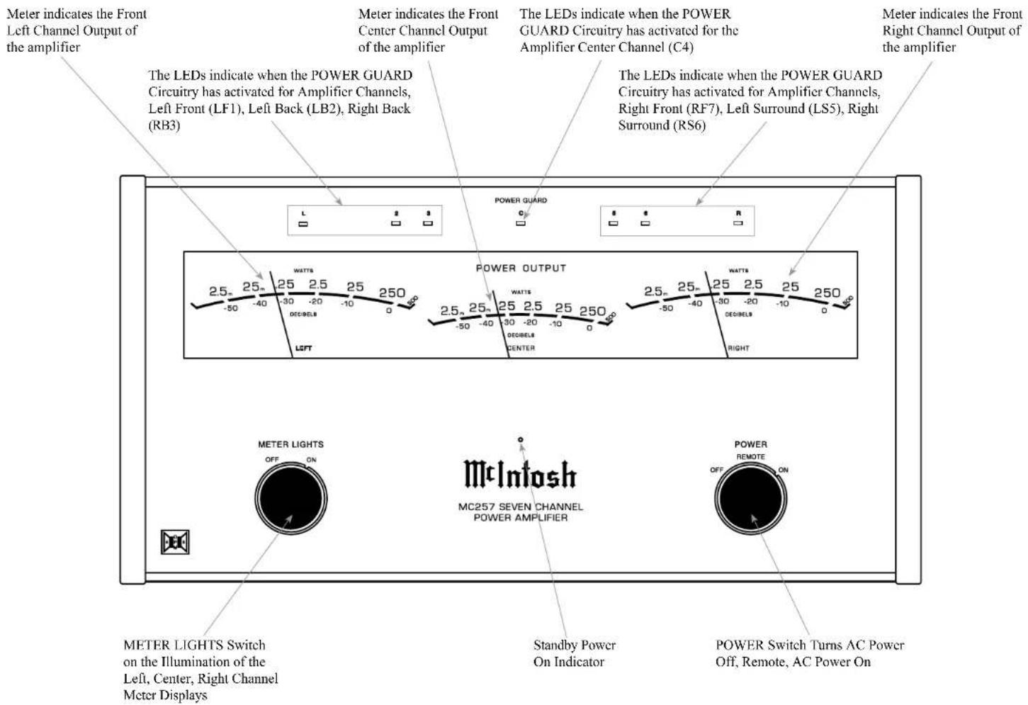
Front Panel Displays and Controls
How to Operate
Power On
There are two ways to have AC Power switched ON to the MC257:
REMOTE Setting
When the MC257 Power Control Connection (ZA and/or ZB) receives a Power Control Signal from a Preamplifier or A/V Control Center, it will turn On
automatically when the MC257 POWER Control is set to the REMOTE Setting. Refer to figure 9.
ON Setting
When the MC257 POWER Control is set to the ON position, it will become active Zone A only. Refer to figure 10. To switch the MC257 OFF, place the POWER Control in the OFF position.

Figure 9

Figure 10
MC257 Channel Operation
There are several Channel Operation Modes. The first operation mode is referred to as Zone A. This occurs when the POWER Control is positioned to ON or set to the REMOTE position and is receiving a Power Control Signal in the ZA connector. When the MC257 is in the Zone A operation mode, the following is a list of Channel Operations:
| Channel Number Channel Function | |
| 1 Left Front | |
| 2 Left Back Surround | |
| 3 Right Back Surround | |
| 4 Center (Front) | |
| 5 Left Surround | |
| 6 Right Surround | |
| 7 Right Front | |
The other operation mode is referred to as Zone A/B when the POWER Control is in the REMOTE position and both the ZA and ZB connectors are receiving Power Control Signals.
MC257 ZONE A and ZONE B OPERATION
| Zone Channel Number Channel Function | ||
| A | 1 | Left Front |
| A | 4 | Center (Front) |
| A | 5 | Left Surround |
| A | 6 | Right Surround |
| A | 7 | Right Front |
| B | 2 | Left |
| B | 3 | Right |
Meters
Rotate the METER LIGHTS Switch to the ON position to Illuminate the three Front Panel Meters for the Left, Center and Right Channels. Refer to figure 11.
Lights Off - Meter lights are turned off, the Meters will continue to indicate the power output.
Note: When Power Control Input of the MC257 is connected to an Audio Preamplifier or A/V
Control Center with Remote Meter Illumination Control, the Meter Illumination will automatically be remotely controlled (On/Off).

Figure 11
Watts- The meters respond to all the musical information being produced by the amplifier. They indicate to an accuracy of at least 95% of the
power output with only a single cycle of a 2000Hz tone burst. Refer to figure 12.
Auto Off Switch
The MC257 incorporates Power Save Circuitry to automatically place the MC257 into the power saving Standby Mode approximately 30 minutes after there has been an absence of an audio input signal.
When there is a Power Control Connection between the MC257 and a Preamplifier or A/V Control Center with Power Save Circuitry, the AUTO OFF Switch in the ENable position is bypassed (located on the Rear Panel of the MC257). AUTO OFF DIS EN Refer to figure 13.
In the event there is no Power Control Figure 13 Connection and the Power Save Circuitry is activating inappropriately relative to your specific use of the MC257, place the AUTO OFF Switch in the DISable position.
Note: If the Power Save Circuitry has switched Power to the MC257 OFF, place the POWER in the OFF Position and then in the ON position to reset the circuitry.
Load Switch
Place the Load Impedance Switch to the 4 Ohms position if the Loudspeakers Connected to the MC257 are not 8 Ohms but 4 Ohms. Refer to figure 14.
AUTO OFF
DIS EN

Figure 13

Figure 14

Figure 12

Technical Description
McIntosh Laboratory, the company who introduced the world's first amplifier that could be called "High Fidelity", has done it again. The McIntosh engineering staff has created a Power Amplifier without compromise, using the most advanced McIntosh circuit design concepts.
The MC257 has a continuous average power output rating of 250 watts and with a peak output current of 25 amperes per channel; making this one of the most advanced amplifiers available today. The distortion limits for the MC257 are no more than 0.005% at rated power output for all frequencies from 20Hz to 20,000Hz. Typical performance at mid frequencies is less than 0.002% . The true distortion readings on the MC257 are so low, it takes special measuring techniques to make accurate readings. The MC257 can deliver the best possible performance from any type of high quality loudspeaker system. Refer to figure 15.
Creating an amplifier with this level of performance did not come easily. Many months of design, testing and measuring were required. Extensive controlled listening tests, the ultimate form of measuring, were made before the final design was accepted.
Design Philosophy
The design philosophy incorporated in the MC257 involved several different techniques, all based on sound scientific logic. Every stage of voltage or current amplification must be as linear as possible prior to the use of negative feedback. McIntosh engineers know how to properly design negative feedback circuits so they contribute to the extremely low distortion performance expected from a McIntosh Amplifier. The typical McIntosh owner would never accept the approximately 100 times higher distortion of many non-feedback designs. Refer to figure 16.

Figure 15
Block Diagram of the Power Amplifier (one channel shown)

flowchart
graph TD
    A["Input Signal"] --> B["AND Gate"]
    B --> C["AND Gate"]
    C --> D["AND Gate"]
    D --> E["AND Gate"]
    E --> F["AND Gate"]
    F --> G["AND Gate"]
    G --> H["AND Gate"]
    H --> I["AND Gate"]
    I --> J["AND Gate"]
    J --> K["AND Gate"]
    K --> L["AND Gate"]
    L --> M["AND Gate"]
    M --> N["AND Gate"]
    N --> O["AND Gate"]
    O --> P["AND Gate"]
    P --> Q["AND Gate"]
    Q --> R["AND Gate"]
    R --> S["AND Gate"]
    S --> T["AND Gate"]
    T --> U["AND Gate"]
    U --> V["AND Gate"]
    V --> W["AND Gate"]
    W --> X["AND Gate"]
    X --> Y["AND Gate"]
    Y --> Z["AND Gate"]
    Z --> AA["AND Gate"]
    AA --> AB["AND Gate"]
    AB --> AC["AND Gate"]
    AC --> AD["AND Gate"]
    AD --> AE["AND Gate"]
    AE --> AF["AND Gate"]
    AF --> AG["AND Gate"]
    AG --> AH["AND Gate"]
    AH --> AI["AND Gate"]
    AI --> AJ["AND Gate"]
    AJ --> AK["AND Gate"]
    AK --> AL["AND Gate"]
    AL --> AM["AND Gate"]
    AM --> AN["AND Gate"]
    AN --> AO["AND Gate"]
    AO --> AP["AND Gate"]
    AP --> AQ["AND Gate"]
    AQ --> AR["AND Gate"]
    AR --> AS["AND Gate"]
    AS --> AT["AND Gate"]
    AT --> AU["AND Gate"]
    AU --> AV["AND Gate"]
    AV --> AW["AND Gate"]
    AW --> AX["AND Gate"]
    AX --> AY["AND Gate"]
    AY --> AZ["AND Gate"]
    AZ --> BA["AND Gate"]
    BA --> BB["AND Gate"]
    BB --> BC["AND Gate"]
    BC --> BD["AND Gate"]
    BD --> BE["AND Gate"]
    BE --> BF["AND Gate"]
    BF --> BG["AND Gate"]
    BG --> BH["AND Gate"]
    BH --> BI["AND Gate"]
    BI --> BJ["AND Gate"]
    BJ --> BK["AND Gate"]
    BK --> BL["AND Gate"]
    BL --> BM["AND Gate"]
    BM --> BN["AND Gate"]
    BN --> BO["AND Gate"]
    BO --> BP["AND Gate"]
    BP --> BQ["AND Gate"]
    BQ --> BR["AND Gate"]
    BR --> BS["AND Gate"]
    BS --> BT["AND Gate"]
    BT --> BU["AND Gate"]
    BU --> BV["AND Gate"]
    BV --> BW["AND Gate"]
    BW --> BX["AND Gate"]
    BX --> BY["AND Gate"]
    BY --> BZ["AND Gate"]
Figure 16

natural_image
Black industrial heat exchanger with cooling fins and internal circuit board (no visible text or symbols)Figure 18
All transistors are selected to have nearly constant current gain over the entire current range they must
cover. Output transistors in particular, have matched uniform current gain, high current bandwidth product and large active region safe operating area. These Power Transistors are the very latest in semiconductor technology and incorporate a new design known as ThermalTrak™. Refer to figure 17. This allows for the instantaneous and accurate monitoring of the Power Transistor Temperature. The MC257 Power Output Circuitry has a specially designed bias circuit to take full advantage of the ThermalTrak™ Power Transistors and thus precisely controls the power amplifier operation over a wide range of music conditions with the benefits of lower distortion and cooler operation. Precision metal film resistors and low dielectric absorption film capacitors are used in all critical circuit locations.

Figure 17
The high efficiency circuit design of the MC257 contributes to low operating temperatures. More than 2800 square inches of heat sink area keep the MC257 operating safely with convection cooling. No fans are needed. Refer to figure 18.
Power Output Meter
The McIntosh MC257 has a large three Meter Wattage Output Meter that responds 95% full scale to a single cycle tone burst at 2kHz. Refer to figure 19. Voltage and current outputs are electronically measured, multiplied and fed to a special circuit that accelerates the pointer movement in the upward direction. When the pointer reaches its peak it pauses only long enough for the human eye to perceive its position, then drops. It is almost 10 times faster than a professional VU meter.

line
| Position | Power Output (Watts) | Voltage (Watts) | | :--- | :--- | :--- | | Left | -10 | 0 | | Center | -10 | 0 | | Right | -10 | 0 | | Bottom Left | -50 | 25 | | Bottom Center | -50 | 25 | | Bottom Right | -50 | 25 | | Top Left | -30 | 25 | | Top Center | -30 | 25 | | Top Right | -30 | 25 | | Top Bottom Left | -40 | 25 | | Top Bottom Center | -40 | 25 | | Top Bottom Right | -40 | 25 | | Top Bottom Left | -50 | 25 | | Top Bottom Center | -50 | 25 | | Top Bottom Right | -50 | 25 | | Top Bottom Left | -20 | 25 | | Top Bottom Center | -20 | 25 | | Top Bottom Right | -20 | 25 | | Top Bottom Left | -20 | 25 | | Top Bottom Center | -20 | 25 | | Top Bottom Right | -20 | 25 | | Top Bottom Left | -30 | 25 | | Top Bottom Center | -30 | 25 | | Top Bottom Right | -30 | 25 | | Top Bottom Left | -30 | 25 | | Top Bottom Center | -30 | 25 | | Top Bottom Right | -30 | 25 | | Top Bottom Left | -40 | 25 | | Top Bottom Center | -40 | 25 | | Top Bottom Right | -40 | 25 | | Top Bottom Left | -40 | 25 | | Top Bottom Center | -40 | 25 | | Top Bottom Right | -40 | 25 | | Top Bottom Left | -50 | 25 | | Top Bottom Center | -50 | 25 | | Top Bottom Right | -50 | 25 | | Top Bottom Left | -50 | 25 | | Top Bottom Center | -50 | 25 | | Top Bottom Right | -50 | 25 | | Top Bottom Left | -10 | 25 | | Top Bottom Center | -10 | 25 | | Top Bottom Right | -10 | 25 | | Top Bottom Left | -10 | 25 | | Top Bottom Center | -10 | 25 | | Top Bottom Right | -10 | 25 | | Top Bottom Left | -20 | 25 | | Top Bottom Center | -20 | 25 | | Top Bottom Right | -20 | 25 | | Top Bottom Left | -20 | 25 | | Top Bottom Center | -20 | 25 | | Top Bottom Right | -20 | 25 | | Top Bottom Left | -30 | 25 | | TopBottom Center | -30 | 25 | | TopBottom Right | -30 | 25 | | TopBottom Left | -30 | 25 | | TopBottom Center | -30 | 25 | | TopBottom Right | -30 | 25 | | TopBottom Left | -40 | 25 | | TopBottom Center | -40 | 25 | | TopBottom Right | -40 | 25 | | TopBottom Left | -40 | 25 | | TopBottom Center | -40 | 25 | | TopBottom Right | -40 | 25 | | TopBottom Left | -50 | 25 | | TopBottom Center | -50 | 25 | | TopBottom Right | -50 | 25 | | TopBottom Left | -50 | 25 | | TopBottom Center | -50 | 25 | | TopBottom Right | -50 | 25 | | TopBottom Left | -100 | 25 | | TopBottom Center | -100 | 25 | | TopBottom Right | -100 | 25 | | TopBottom Left | -100 | 25 | | TopBottom Center | -100 | 25 | | TopBottom Right: Power OUTPUT | Power OUTPUT (Watts) / Power OUTPUT (Watts) / Power OUTPUT (Watts) | Power OUTPUT (Watts) / Power OUTPUT (Watts) / Power OUTPUT (Watts) | Power OUTPUT (Watts) / Power OUTPUT (Watts) / Power OUTPUT (Watts) | Power OUTPUT (Watts) / Power OUTPUT (Watts) / Power OUTPUT (Watts) | | Bottom Left: Power OUTPUT | Power OUTPUT: Power OUTPUT | Power OUTPUT: Power OUTPUT | | Bottom Center: Power OUTPUT | | Bottom Right: Power OUTPUT | | Bottom Left: Power OUTPUT | | Bottom Center: Power OUTPUT | | Bottom Right: Power OUTPUT | | Bottom Left: Power OUTPUT | | Bottom Center: Power OUTPUT | | Bottom Right: Power OUTPUT | | Bottom Left: Power OUTPUT | | Bottom Center: Power OUTPUT | | Bottom Right: Power OUTPUT | | Bottom Left: Power OUTPUT | | Bottom Center: Power OUTPUT | | Bottom Right: Power OUTPUT | | Bottom Left: Power OUTPUTFigure 19

Technical Description, con't
Protection Circuits
The MC257 incorporates the McIntosh Sentry Monitor Output Transistor Protection Circuit. Refer to
Figure 20. There is absolutely no compromise in sonic performance with this circuit, and it ensures safe operation of the amplifier under even the most extreme operating conditions. The different

Figure 20
types of protection circuits incorporated in the MC257 insure a long and safe operating life. This is just one of the many characteristics of McIntosh Power Amplifiers that make them world famous.
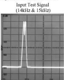
The MC257 also includes the unique patented McIntosh Power Guard circuit. Power Guard eliminates the possibility of ever overdriving the amplifier into clipping. Refer to figures 21, 22 and 23. An overdriven amplifier can produce both audible and inaudible distortion levels exceeding 40%.
The audible distortion is unpleasant to hear, but the inaudible ultrasonic distortion is also undesirable, since it can damage valuable loudspeaker system tweeters. You will never experience the harsh and damaging distortion due to clipping.
line
Input Test Signal (14kHz & 15kHz) | Time (s) | Input Test Signal (dB) | | :--- | :--- | | 0 | 0 | | 1 | 20 | | 2 | 30 | | 3 | 40 | | 4 | 50 | | 5 | 60 | | 6 | 70 | | 7 | 80 | | 8 | 90 | | 9 | 100 | | 10 | 110 | | 11 | 120 | | 12 | 130 | | 13 | 140 | | 14 | 150 | | 15 | 160 | | 16 | 170 | | 17 | 180 | | 18 | 190 | | 19 | 200 | | 20 | 210 | | 21 | 220 | | 22 | 230 | | 23 | 240 | | 24 | 250 | | 25 | 260 | | 26 | 270 | | 27 | 280 | | 28 | 290 | | 29 | 300 | | 30 | 310 | | 31 | 320 | | 32 | 330 | | 33 | 340 | | 34 | 350 | | 35 | 360 | | 36 | 370 | | 37 | 380 | | 38 | 390 | | 39 | 400 | | 40 | 410 | | 41 | 420 | | 42 | 430 | | 43 | 440 | | 44 | 450 | | 45 | 460 | | 46 | 470 | | 47 | 480 | | 48 | 490 | | 49 | 500 | | 50 | 510 | | 51 | 520 | | 52 | 530 | | 53 | 540 | | 54 | 550 | | 55 | 560 | | 56 | 570 | | 57 | 580 | | 58 | 590 | | 59 | 600 | | 60 | 610 | | 61 | 620 | | 62 | 630 | | 63 | 640 | | 64 | 650 | | 65 | 660 | | 66 | 670 | | 67 | 680 | | 68 | 690 | | 69 | 700 | | 70 | 710 | | 71 | 720 | | 72 | 730 | | 73 | 740 | | 74 | 750 | | 75 | 760 | | 76 | 770 | | 77 | 780 | | 78 | 790 | | 79 | 800 | | 80 | 810 | | 81 | 820 | | 82 | 830 | | 83 | 840 | | 84 | 850 | | 85 | 860 | | 86 | 870 | | 87 | 880 | | 88 | 890 | | 89 | 900 | | 90 | 910 | | 91 | 920 | | 92 | 930 | | 93 | 940 | | 94 | 950 | | 95 | 960 | | 96 | 970 | | 97 | 980 | | 98 | 990 | | 99 | 1000 | The chart displays a single data series with 'Input Test Signal' as the y-axis label. The x-axis label is 'Time (s)' and 'Signal'. There are no additional data series labeled '14kHz & '15kHz'. The values for the series are estimated based on the provided code.Figure 21
The Power Guard circuit is a waveform comparator, monitoring both the input and output waveforms. Under normal operating conditions, there are no differences between the shape of these waveforms. If the amplifier is overdriven, there will be a difference between the two signal waveforms. When the difference exceeds 0.3%, the Power Guard activates the PG light and a dynamic electronic attenuator at the amplifier input reduces the input volume just enough to prevent any further increase in distortion. The Power Guard circuit acts so fast that there are absolutely no audible side effects and the sonic purity of the music reproduction is perfectly preserved. The MC257 Power Amplifier with Power Guard is not limited to just the rated power output, but will actually produce distortion free output well above its rated power due to the McIntosh philosophy of conservative design.
Without Power Guard

line
| X-Axis Label | Y-Axis Value | |---|---| | 1 | -25 | | 2 | -30 | | 3 | -28 | | 4 | -32 | | 5 | -26 | | 6 | -29 | | 7 | -27 | | 8 | -24 | | 9 | -26 | | 10 | -23 | | 11 | -27 | | 12 | -25 | | 13 | -28 | | 14 | -26 | | 15 | -29 | | 16 | -27 | | 17 | -24 | | 18 | -26 | | 19 | -28 | | 20 | -25 | | 21 | -27 | | 22 | -26 | | 23 | -28 | | 24 | -25 | | 25 | -26 | | 26 | -29 | | 27 | -27 | | 28 | -28 | | 29 | -26 | | 30 | -27 | | 31 | -28 | | 32 | -25 | | 33 | -26 | | 34 | -29 | | 35 | -27 | | 36 | -28 | | 37 | -26 | | 38 | -27 | | 39 | -28 | | 40 | -25 | | 41 | -26 | | 42 | -29 | | 43 | -27 | | 44 | -28 | | 45 | -26 | | 46 | -27 | | 47 | -28 | | 48 | -25 | | 49 | -26 | | 50 | -29 | | 51 | -27 | | 52 | -28 | | 53 | -26 | | 54 | -27 | | 55 | -28 | | 56 | -25 | | 57 | -26 | | 58 | -29 | | 59 | -27 | | 60 | -28 | | 61 | -26 | | 62 | -27 | | 63 | -28 | | 64 | -25 | | 65 | -26 | | 66 | -29 | | 67 | -27 | | 68 | -28 | | 69 | -26 | | 70 | -27 | | 71 | -28 | | 72 | -25 | | 73 | -26 | | 74 | -29 | | 75 | -27 | | 76 | -28 | | 77 | -26 | | 78 | -27 | | 79 | -28 | | 80 | -25 | | 81 | -26 | | 82 | -29 | | 83 | -27 | | 84 | -28 | | 85 | -26 | | 86 | -27 | | 87 | -28 | | 88 | -25 | | 89 | -26 | | 90 | -29 | | 91 | -27 | | 92 | -28 | | 93 | -26 | | 94 | -27 | | 95 | -28 | | 96 | -25 | | 97 | -26 | | 98 | -29 | | 99 | -27 | | 100 | -28 |Figure 22
With Power Guard
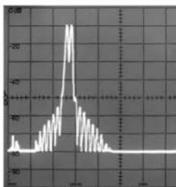
Figure 23
Power Supply Circuits
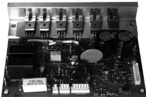
To compliment the design of the MC257 Power Amplifier Circuitry, there is a high current high voltage power supply. Refer to figures 24 and 27.
natural_image
Close-up of an electronic circuit board with various components and traces (no visible text or symbols)Figure 27
The very large Power Transformer can supply over 13 amps of current. Refer to figure 25 (golf ball is for size comparison).

natural_image
Close-up of a coiled black toroidal coil with metallic end caps, next to a white spherical object (no text or symbols visible)Figure 25

flowchart
graph LR
    A["AC POWER"] --> B["CIRCUIT BREAKER"]
    B --> C["POWER RELAY"]
    C --> D["INRUSH CURRENT LIMITER"]
    D --> E["TOROID POWER TRANSFORMER"]
    E --> F["4Q/8Ω MODE CONTROL"]
    F --> G["8Ω MAIN SUPPLY"]
    F --> H["4Q MAIN SUPPLY"]
    C --> I["POWER SAVE CONTROL"]
    I --> C
    E --> J["LOW VOLTAGE SUPPLY"]
    F --> K["THERMAL SENSE"]
Figure 24
It is enclosed in the legendary McIntosh Potted Enclosures and weighs 30 lbs. The six super size main filter capacitors can store over 350 Joules of energy which is necessary for the wide dynamic range that "Digital Audio" demands. Refer to figure 26.

natural_image
Stack of black cylindrical capacitors with printed labels, arranged on a metal base (no readable text beyond branding)Figure 26
The power amplifier draws high current from the AC power line. Therefore, it is important that they plug directly into the wall outlet.
Also, most owners desire one power switch for the whole audio system. The MC257 is equipped with a circuit that provides remote Power Control from a McIntosh A/V Control Center. When the A/V Control Center is switched On, a (+5V) signal operates the power relay in the MC257. The MC257 also has two remote Power Control Out Jacks. The Power Control signal from these jacks is delayed by a fraction of a second so that the turn on power surge of the next power amplifier occurs at a later time. This helps prevent power circuit overload that could trip circuit breakers or blow fuses, a very important feature in high power Home Systems employing multiple MC257 Power Amplifiers.


Photos

Specifications
Power Output (All Seven Channels)
Minimum sine wave continuous average power output per channel, all channels operating is:
200 watts into a 4 ohm or 8 ohm load
Power Output (Three Front Channels)
Minimum sine wave continuous average power output per channel operating is:
250 watts into a 4 ohm or 8 ohm load
Output Load Impedance
8 and 4 ohms
Rated Power Band
20Hz to 20,000Hz
Total Harmonic Distortion
0.005% maximum harmonic distortion at any power level from 250 milliwatts to rated power, 20Hz to 20,000Hz
Dynamic Headroom
3.3dB
Frequency Response
+0, -0.25dB from 20Hz to 20,000Hz
+0, -3dB from 10Hz to 100,000Hz
Input Sensitivity (for rated output)
2.2 Volt Balanced with a 4 ohm Loudspeaker
1.1 Volt Unbalanced with a 4 ohm Loudspeaker
3.0 Volt Balanced with an 8 ohm Loudspeaker
1.6 Volt Unbalanced with an 8 ohm Loudspeaker
Signal To Noise Ratio (A-Weighted)
108dB below rated output
Intermodulation Distortion
0.005% maximum, if the instantaneous peak power output does not exceed twice the rated power output or less per channel with all channels operating for any combination of frequencies from 20Hz to 20,000Hz
Wide Band Damping Factor
Greater than 70 at 4 ohms
Greater than 140 at 8 ohms
Input Impedance
20,000 ohms Balanced
10,000 ohms Unbalanced
Voltage Gain
29dB
Power Guard
Less than 2% THD with up to 14dB overdrive at 1,000Hz
Power Control Inputs ZA and ZB
5-15VDC, less than 1mA
Power Control Output ZA and ZB
12VDC, 50mA maximum total
Output is delayed 0.2 seconds from turn On
Power Requirements
Field AC Voltage conversion of the MC257 is not possible. The MC257 is factory configured for one of the following AC Voltages:
100 Volts, 50/60Hz at 14.4 Amps
110 Volts, 50/60Hz at 13.0 Amps
120 Volts, 50/60Hz at 12.0 Amps
127 Volts, 50/60Hz at 12.0 Amps
220 Volts, 50/60Hz at 7.5 Amps
230 Volts, 50/60Hz at 6.5 Amps
240 Volts, 50/60Hz at 6.5 Amps
Standby: less than 0.5 watt
Note: Refer to the rear panel of the MC257 for the correct voltage.
Overall Dimensions
Width is 17-1/2 inches (44.5cm)
Height is 9-7/16 inches (23.9cm) including feet
Depth is 21 inches (53.3cm) including the Front Panel and Cables
Weight
95 pounds (43 kg) net, 128 pounds (58 kg) in shipping carton
Shipping Carton Dimensions
Width is 29-1/2 inches (74.9cm)
Height is 17 inches (43.2cm)
Depth is 29 inches (73.7cm)
Packing Instructions
In the event it is necessary to repack the equipment for shipment, the equipment must be packed exactly as shown below. It is very important that the four plastic feet are attached to the bottom of the equipment. Four 1/4 - 20 x 2-1/2 inch screws and washers must be used to fasten the unit securely to the bottom pad and shipping skid. This will ensure the proper equipment location on the bottom pad. Failure to do this will result in shipping damage.
Use the original shipping carton and interior parts only if they are all in good serviceable condition. If a shipping carton or any of the interior part(s) are needed, please call or write Customer Service Department of McIntosh Laboratory. Refer to page 2. Please see the Part List for the correct part numbers.
Quantity Part Number Description
1 034052 Shipping carton top
1 034051 Shipping carton bottom
2 034054 Foam Pad (top and bottom)
2 034186 Foam Pad (front and rear)
2 034187 Foam Pad (sides)
1 034136 Inner carton top
1 034137 Inner carton bottom
1 034188 Foam Pad (inner carton)
1 034479 Shipping skid
4 101212 1/4 - 20x2-1/4 cap screw
4 104058 Flat washer


McIntosh Laboratory, Inc.
2 Chambers Street
Binghamton, NY 13903
www.mcintoshlabs.com
The continuous improvement of its products is the policy of McIntosh Laboratory Incorporated who reserve the right to improve design without notice. Printed in the U.S.A.


- Important Safety Information is supplied in a separate document “Important Additional Operation Information Guide”
- Thank You
- Please Take A Moment
- Technical Assistance
- Customer Service
- Table of Contents
- General Information
- Connector and Cable Information
- XLR Connectors
- Power Control Connector
- Output Terminal Connector
- Introduction
- Performance Features
- - Power Output
- • Balanced and Unbalanced Inputs
- - Power Guard
- - Zone B Operation
- - Sentry Monitor and Thermal Protection
- • Special Power Supply
- - Illuminated Power Meters
- • McIntosh Custom Binding Posts
- - Glass Front Panel and Super Mirror Chassis Finish
- Dimensions
- Installation
- Output Terminals
- How to Connect
- Spade Lug or Wire Connections:
- How to Operate
- Power On
- REMOTE Setting
- ON Setting
- MC257 Channel Operation
- Meters
- Auto Off Switch
- Load Switch
- Technical Description
- Design Philosophy
- Power Output Meter
- Technical Description, con't
- Protection Circuits
- Power Supply Circuits
- Specifications
- Power Output (All Seven Channels)
- Power Output (Three Front Channels)
- Output Load Impedance
- Rated Power Band
- Total Harmonic Distortion
- Dynamic Headroom
- Frequency Response
- Input Sensitivity (for rated output)
- Signal To Noise Ratio (A-Weighted)
- Intermodulation Distortion
- Wide Band Damping Factor
- Input Impedance
- Voltage Gain
- Power Guard
- Power Control Inputs ZA and ZB
- Power Control Output ZA and ZB
- Power Requirements
- Overall Dimensions
- Weight
- Shipping Carton Dimensions
- Packing Instructions
- Quantity Part Number Description
Brand : MCINTOSH
Model : MC257
Category : Audio Receiver