/DK — Cooker — Mode d'emploi PDF")
KP 648 MS (X)/DK - Cooker INDESIT - Free user manual and instructions
Find the device manual for free KP 648 MS (X)/DK INDESIT in PDF.

| Product Type | Freestanding Gas Cooker with Electric Oven |
| Brand | Indesit |
| Model | KP 648 MS (X)/DK |
| Dimensions (H x W x D) | 900 mm x 600 mm x 600 mm |
| Power Supply | 230 V ~ 50 Hz, 2850 W |
| Oven Volume | 53 liters |
| Number of Gas Burners | 4 |
| Burner Types | Auxiliary (1.00 kW), Semi-rapid (1.65 kW), Rapid (3.00 kW), Triple Ring (3.25 kW) |
| Oven Functions | Convectional, Baking, Fast Cooking, Multi-cooking, Pizza, Grill, Ventilated Grill |
| Timer | Mechanical timer, up to 120 minutes |
| Ignition | Automatic electric ignition with pushbutton |
| Safety Features | Thermocouple flame failure device on gas burners; cooling fan; oven door safety |
| Interior Light | 15 W, 230/240 V, socket E14, high temperature (300 °C) |
| Cleaning | Enamel interior; manual cleaning with warm water and mild detergent; self-cleaning panels not specified |
| Gas Connection | 1/2" cylindrical male thread (G 1/2"); adaptable for natural gas, LPG, or city gas |
| Electrical Connection | Requires earth; plug or direct connection via omnipolar circuit breaker (min. 3 mm contact opening) |
| Weight | Approximately 60 kg (estimate) |
Frequently Asked Questions - KP 648 MS (X)/DK INDESIT
User questions about KP 648 MS (X)/DK INDESIT
0 question about this device. Answer the ones you know or ask your own.
Ask a new question about this device
Download the instructions for your Cooker in PDF format for free! Find your manual KP 648 MS (X)/DK - INDESIT and take your electronic device back in hand. On this page are published all the documents necessary for the use of your device. KP 648 MS (X)/DK by INDESIT.
USER MANUAL KP 648 MS (X)/DK INDESIT
Instructions for use and installation
DE Herd
Instructions for use and installation
natural_image
Simple line drawing of a ladder leaning against a vertical pole, with arrows indicating motion direction (no text or symbols)ABB:3
natural_image
Pure mechanical assembly diagram showing pipe connection and valve (no text or symbols)PRAKTISCHE BACK-/BRATHINWEISE
natural_image
Simple line drawing of a house interior with a stove and roof, no text or symbols presentAbb.6
natural_image
Simple line drawing of a house interior with a stove and steam rising (no text or symbols)natural_image
Diagram showing a device with a screwdriver inserted into a housing, with an inset close-up of the component (no text or symbols present)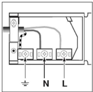
natural_image
Three identical line-drawn cooking pots with crossed x marks, no text or symbols present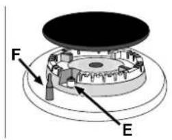
Ovnen "Fast cooking"
natural_image
Simple line drawing of a ladder leaning against a vertical post, with arrows indicating motion direction (no text or symbols)FIGUR 3
FIGUR 2

natural_image
Pure technical line drawing of a mechanical component with no text or symbolsPRAKTISKE RÅD TIL TILBEREDNING AF MAD
| Placering af vælgeknap | Mad der skal tilberedes Vægt | (Kg) | Hyldeplac-ering set fra neden | Foropvarmningstid (minutter) | Placering af termostatk-nap | Tilberednin-gstid (minutter) |
| Ovn | Lasagne | 2,5 | 3 | 10 | 200 | 55-60 |
| Cannelloni | 2,5 | 3 | 10 | 200 | 40-45 | |
| Ovnbagt pasta | 2,2 | 3 | 10 | 200 | 50-55 | |
| Kalvekød | 1,7 | 2 | 10 | 210 | 80-90 | |
| Kylling | 1,5 | 3 | 10 | 200 | 70-80 | |
| Kalkun-roulade | 2,5 | 3 | 10 | 200 | 80-90 | |
| And | 1,8 | 3 | 10 | 200 | 90-100 | |
| Kanin | 2,0 | 3 | 10 | 200 | 80-90 | |
| Svinekam | 1,5 | 3 | 10 | 200 | 70-80 | |
| Lammelår | 1,8 | 3 | 10 | 200 | 80-90 | |
| Makreller | 1,3 | 3 | 10 | 200 | 30-40 | |
| Havrude | 1,5 | 3 | 10 | 180 | 30-40 | |
| ∅rred bagt i stanniol-papir | 1,0 | 3 | 10 | 200 | 30-35 | |
| Pizza | 0,6 | 3 | 15 | 210 | 15-20 | |
| Småkager | 0,5 | 4 | 15 | 180 | 25-30 | |
| Tærte | 1,1 | 3 | 15 | 180 | 30-35 | |
| Chokoladekage | 1,0 | 3 | 15 | 165 | 50-60 | |
| Hævede tærter | 1,0 | 4 | 15 | 165 | 50-60 | |
| Grill | Søtunger | 1 | 4 | 5 | - | 6 |
| Rejespid | 1 | 4 | 3 | - | 4 | |
| Torskefilet | 1 | 4 | 3 | - | 10 | |
| Grillede grøntsager | 1 | 4 | - | - | 8-10 | |
| Kalvebøf | 1 | 4 | 5 | - | 20-25 | |
| Koteletter | 1,5 | 4 | 5 | - | 20-25 | |
| Hamburger | 1 | 4 | 3 | - | 10-15 | |
| Pølser | 1,7 | 4 | 5 | - | 20-25 | |
| Toast | nr. 4 | 4 | 3 | - | 2-3 | |
| Med drejeindretning (hvis til stede) | ||||||
| Kalvekød på spid | 1.0 | - | - | - | 80-90 | |
| Kylling på spid | 1.5 | - | - | - | 80-90 | |
| Lam på spid | 1.0 | - | - | - | 80-90 |
natural_image
Simple line drawing of a house interior with a stove, roof, and piping (no text or symbols)fig.6

natural_image
Simple line drawing of a house interior with a stove, roof, and ventilation system (no text or symbols)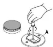
fig.9
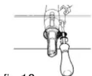
fig.10
natural_image
Diagram showing a mechanical component inserted into a housing, with an inset magnified view highlighting the component (no text or symbols present)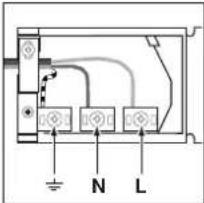
Congratulations for choosing an Indesit appliance, which you will find is dependable and easy to use. We recommend you read though this booklet for the best performance and to extend the life of your appliance. Thank you.
WARNINGS
THESE INSTRUCTIONS ARE ONLY VALID FOR THE COUNTRIES OF DESTINATION WHOSE SYMBOLS ARE SHOWN IN THE BOOKLET AND ON THE APPLIANCE RATING PLATE.
- This appliance has been designed for private, non-professional domestic use in the home.
- Read this instruction booklet carefully, as it provides important advice regarding safe installation, use and maintenance. Keep this booklet in a safe place for future reference.
- The oven accessories that may come into contact with food are made of materials which comply with the provisions set forth by the EEC Directive 89/109 of 21/12/88 and the applicable national norms in force.
- After removing the packaging, check that the appliance is intact. If in doubt, do not use the appliance and contact a qualified serviceman.
- Some parts are covered with a removable scratch-proof film. Before using the appliance, the film should be removed and the underlying part cleaned with a cloth and a non-abrasive household cleaning product. When switching on the appliance for the first time, we recommend you heat the oven at the maximum temperature setting for about 30 minutes with nothing in it to eliminate any residue from manufacture.
- All installation and adjustment operations should be carried out by a qualified serviceman in accordance with the applicable norms in force. Specific instructions are provided in the section intended for the installer.
- Before connecting the appliance, make sure that the data on the rating plate (situated underneath the appliance and on the last page of this instruction booklet) correspond to the mains electricity and gas supplies.
- During operation, the oven glass door and adjacent parts of the appliance become hot. Make sure, therefore, that children do not touch the appliance.
- Check that the capacity of the electrical system and the power outlets are suitable for the maximum power of the appliance, indicated on the rating plate. If in doubt, consult a qualified technical engineer.
- Check the condition of the gas connection pipe regularly and have it replaced by a qualified technical engineer as soon as it shows any signs of wear or anomaly.
- Under no circumstances should the user replace the power supply cable or the gas connection pipe of this appliance. In the event of damage or the necessity for replacement, contact an authorised service centre only.
- Do not leave the appliance plugged in if it is not in use. Switch off the main switch and turn off the gas supply when the appliance is not in use.
- The burners and the cast-iron pan supports remain hot for a long time after use. Do not touch them.
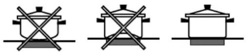
- To avoid accidental spills, do not use cookware with uneven or warped bottoms on the burners.
-
Never use flammable liquids such as alcohol or gasoline, etc. near the appliance when it is in use.
-
If the cooker is placed on a pedestal, take the necessary precautions to prevent the same from sliding off the pedestal itself.
- If the appliance is fitted with a lid, any boiled over liquid should be removed from the hob before shutting it.
- Where present, do not shut the lid if the hob is still hot.
- do not use steam cleaners to clean your oven
- For the best performance of your burners, keep the following in mind: All types of pans can be used on the burners. The important thing is that the bottom should be completely even.
natural_image
Three identical diagrams showing a cooking pot with crossed x marks on a surface, next to a similar cooking pot with crossed x marks on a flat base (no text or symbols)This appliance conforms to the following European Economic Community directives:
- 73/23/EEC of 19/02/73 (Low Voltage) and subsequent modifications;
- 89/336/EEC of 03/05/89 (Electromagnetic Compatibility) and subsequent modifications;
- 90/336/EEC of 29/06/90 (Gas) and subsequent modifications;
- 93/68/EEC of 22/07/93 and subsequent modifications.
CE
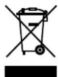
Disposal of old electrical appliances
The European Directive 2002/96/EC on Waste Electrical and Electronic Equipment (WEEE), requires that old household electrical appliances must not be disposed of in the normal unsorted municipal waste stream. Old appliances must be collected separately in order to optimise the recovery and recycling of the materials they contain and reduce the impact on human health and the environment. The crossed out “wheeled bin” symbol on the product reminds you of your obligation, that when you dispose of the appliance it must be separately collected.
Consumers may take their old appliance to public waste collection areas, other communal collection areas, or if national legislation allows return it to a retailer when purchasing a similar new product.
All major household appliance manufacturers are active in the creation of systems to manage the collection and disposal of old appliances.
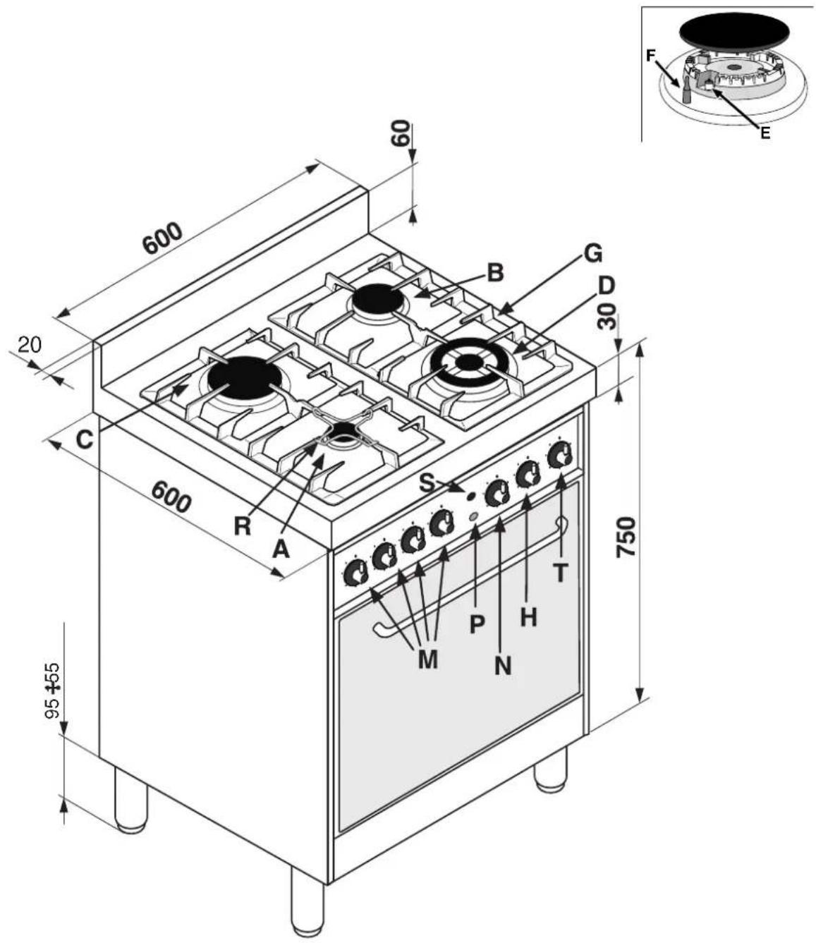
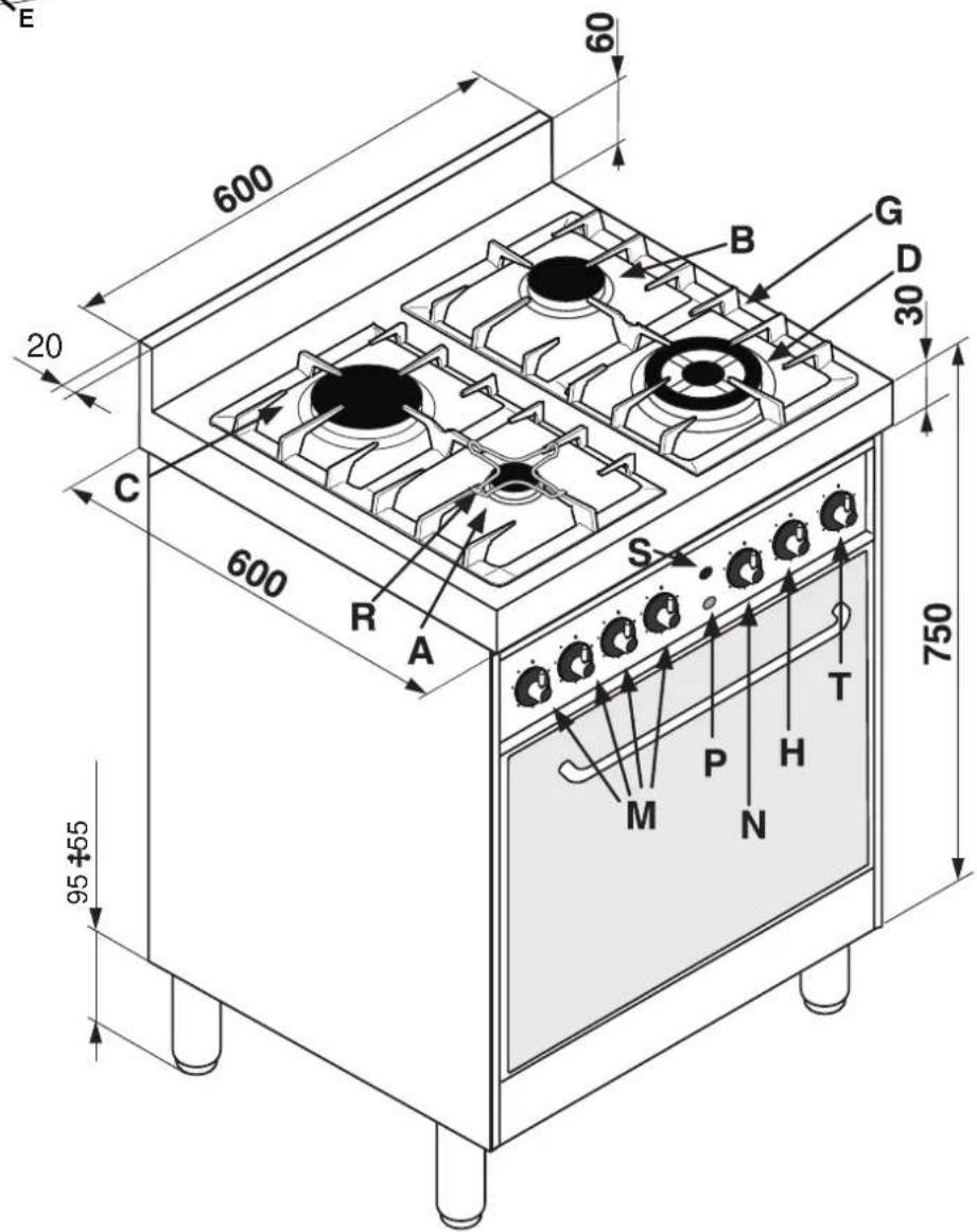
A Auxiliary gas burner
B Semi-rapid gas burner
C Rapid gas burner
D Triple ring gas burner
G Support grid for cookware
R Reducing pan stands
M Control knobs for gas burners
T Timer
E Ignitor for Gas Burners
F Safety Device - Activates if the flame accidentally goes
out (spills, drafts, etc.), interrupting the supply of gas to the burner.
H Electric oven selector knob (cooking mode selection)
N Electric oven thermostat knob (temperature selection)
S Electric heating element indicator light
P Ignition Pushbutton for gas burners
HOB OPERATION
The burners are fitted with automatic ignition and a thermocouple safety device, which automatically cuts off the gas from the burner in a few seconds if the flame accidentally goes out during operation.
The burners differ in size and power. Choose the most appropriate one for the diameter of the cookware being used. Each burner can be regulated with the corresponding control knob "M" by using one of the following settings:
Off
High flame
Low flame
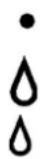
The symbols near the knobs show the position of the relative burner on the hob.
Toignite a burner, proceed as follows:
- turn the relative knob counter-clockwise until the pointer is on the high-flame symbol;
- press the knob down fully and activate the automatic gas ignition by pushing at the same time the button "P" marked with the symbol ☆
- keep the knob pressed down for about 10 seconds with the flame lit to allow the safety thermocouple to be heated;
- release the knob, checking that the flame is stable. If it is not, repeat the operation.
For minimum power, turn the knob towards the low flame symbol. Intermediate positions are possible by simply putting the knob anywhere between the high and the low flame symbol.
To turn off the burner, turn the knob clockwise to the off position "0".
Important:
- Do not activate the automatic ignition device for more than 15 consecutive seconds.
- Difficulty in ignition is sometimes due to air inside the gas duct.
- If a burner flame accidentally goes out, the gas continues to exit for a few moments before the safety device activates. Turn the control knob to the off position and do not attempt ignition again for at least 1 minute, thereby letting the gas disperse, which could otherwise be a danger.
- When the appliance is not in operation, check that the knobs are in the off position "0". The main gas supply cut-off cock should also be closed.
Using the burners:
To obtain maximum efficiency from the burners, it is advisable to only use pans with a diameter suitable for the burner being used, so that the flame does not extend beyond the pan base (see following table). When a liquid starts boiling, it is advisable to turn the flame down just enough to keep the liquid simmering.
| Burner Diameter of the pan in cm. | |
| Auxiliary A from 6 to 14 | |
| Semi-rapid B | from 15 to 20 |
| Rapid C | from 21 to 30 |
| Triple ring D | from 24 to 30 |
The hob is fitted with reducing pan stands (fig. 1), which should only be used on auxiliary burner "A".
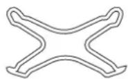
fig.1
TIMER
Turn the timer knob with symbol anti-clockwise and set the marker to symbol (manual). Turn the oven on at the selector knob and set the desired temperature on the thermostat knob. To turn the oven off, turn the timer knob back to its initial position "0".
Operation with cooking time programming
Turn the timer knob clockwise, setting the marker to the desired cooking time (from 10 to 120 minutes). Turn the oven on at the selector knob and set the desired temperature on the thermostat knob. Once the countdown is over, a buzzer will sound, and will stop doing so after 1 minute or if you press any button whatsoever.
Remember that the timer is deactivated when cooking starts (be it immediate or programmed).
Cooling ventilation
In order to cool down the temperature of their exterior, some models are fitted with a cooling fan that comes on when the programme selector knob "H" is turned. In this case, the fan is always on and a normal flow of air can be heard exiting between the oven door and the control panel.
Note: when cooking is done, the fan stays on, even if knob "N" is set to "0", until the oven has cooled down sufficiently.
In "Fast cooking" mode, the fan comes on automatically only when the oven is hot.
Once you have removed the food from the oven, we recommend you leave the oven door ajar for a few minutes: this will drastically reduce the duration of the cooling cycle. The process is controlled by an additional thermostat and can consist of one or more cycles.
Warning: The first time you use your appliance, we recommend that you set the thermostat to the highest setting and leave the oven on for about half an hour with nothing in it, with the oven door shut. Then, open the oven door and let the room air. The odour that is often detected during this initial use is due to the evaporation of substances used to protect the oven during storage and until it is installed.
Warning: Place the dripping pan provided on the bottom rack of the oven to prevent any sauce and/or grease from dripping onto the bottom of the oven only when grilling food or when using the rotisserie (only available on certain models). For all other types of cooking, never use the bottom rack and never place anything on the bottom of the oven when it is in operation because this could damage the enamel coating. Always place your cookware (dishes, aluminium foil, etc.) on the grid provided with the appliance inserted especially along the oven rack guides.
- In this mode only the interior light are switched on: ideal for fast defrosting.
Convectional Mode
Position of thermostat knob "H": Between 40°C and MAX.
On this setting, the top and bottom heating elements come on. This is the classic, traditional type of oven which has been perfected, with exceptional heat distribution and reduced energy consumption. The convection oven is still unequalled when it comes to cooking dishes made up of several ingredients, e.g. cabbage with ribs, local stockfish recipes, tender veal with rice, etc... Excellent results are achieved when preparing beef- or veal-based dishes as well: braised meats, stew, goulash, wild game, ham etc., which need to cook slowly and require basting or the addition of liquid. It nonetheless remains the best system for cooking pastries as well as fruit and cooking casseroles in the oven. When cooking in convection mode, use only one rack, as the temperature would not be distributed evenly on several racks. Using the different rack heights available, you can balance the amount of heat between the top and the bottom of the oven. Select from among the various rack heights based on whether the dish needs more or less heat from the top.
Baking Mode
Position of thermostat knob "H": Between 40°C and MAX.
The rear heating element and the fan come on, guaranteeing delicate heat distributed uniformly throughout the oven. The electricity absorption in this cooking mode is only 1600 W. It is ideal for baking and cooking delicate foods - especially cakes that need to rise - and for the preparation of certain tartlets on 3 racks at the same time. Here are a few examples: cream puffs, sweet and savoury biscuits, savoury puffs, Swiss rolls and small portions of vegetables au gratin, etc....
"Fast cooking" Mode
Position of thermostat knob "H": Between 40°C and MAX.
The heating elements and the fan come on, guaranteeing constant heat distributed uniformly throughout the oven. This mode is especially recommended for cooking pre-packed food quickly (as pre-heating is not necessary), such as for example: frozen or pre-cooked food) as well as for a few "home-made" dishes. The best results when cooking using the "Fast cooking" mode are obtained if you use one cooking rack only (the second from the bottom).
Multi-cooking Mode

Position of thermostat knob "H": Between 40°C and MAX. The heating elements, as well as the fan, will come on. Since the heat remains constant and uniform throughout the oven, the air cooks and browns food uniformly over its entire surface. With this mode, you can also cook various dishes at the same time, as long as their respective cooking temperatures are the same. A maximum of 2 racks can be used at the same time, following the instructions in the section entitled: "Cooking On More Than One Rack". This cooking mode is particularly recommended for dishes requiring a gratin finish or for those requiring considerably prolonged cooking times, such as for example: lasagne, pasta bakes, roast chicken and potatoes, etc... Moreover, the excellent heat distribution makes it possible to use lower temperatures when cooking roasts. This results in less loss of juices, meat which is more tender and a decrease in the loss of weight of the roast. The Multicooking mode is especially suited for cooking fish, which can be prepared with the addition of a limited amount of condiments, thus maintaining their flavour and appearance. Excellent results can be attained when cooking vegetable-based side dishes like courgettes, aubergines, peppers, etc.
Desserts: this mode is also perfect for baking leavened cakes. Moreover, this mode can also be used to thaw quickly white or red meat and bread by setting the temperature to 80 °C. To defrost more delicate foods, set the thermostat to 60°C or use only the cold air circulation feature by setting the thermostat to 0°C.
Pizza Mode
Position of thermostat knob "H": Between 40°C and MAX.
The bottom and circular heating elements, as well as the fan, will come on. This combination rapidly heats the oven due to the large amounts of power used by the appliance (2800 W), which results in the production of considerable heat coming prevalently from the bottom. The pizza mode is ideal for foods requiring high temperatures to cook, like pizzas and large roasts. Only use one dripping pan or rack at a time. However, if more than one is used, these must be switched halfway through the cooking process.
Grill
Position of thermostat knob "H": Between 40°C and MAX.
The extremely high and direct temperature of the grill makes it possible to brown the surface of meats and roasts while locking in the juices to keep them tender. The grill is also highly recommended for dishes that require a high temperature on the surface: such as beef steaks, veal, rib steak, filets, hamburgers etc...
Some grilling examples are included in the "Practical Cooking Advice" paragraph.
Important: when using the grill, the oven door must be kept shut.
The “Ventilated Grill” is extremely useful for grilling foods rapidly, as the distribution of heat makes it possible not only to brown the surface, but also to cook the bottom part. This mode can also be used for browning foods at the end of the cooking process.
CLEANING AND CARE
Before cleaning your oven, or performing maintenance, disconnect it from the power supply.
To extend the life of your oven, it must be cleaned frequently, keeping in mind that:
- The self-cleaning panels (if present) and the enameled parts should be washed with warm water - abrasive powders and corrosive substances should be avoided;
- The inside of the oven should be cleaned immediately after use with warm water and soap; the soap should be rinsed away and the interior dried thoroughly;
- Stainless steel can be stained if it remains in contact with aggressive detergents (containing phosphorus) or water with a high lime content. We recommend that you rinse these parts thoroughly and dry them well after cleaning. It is also a good idea to dry any water spills;
- Never line the bottom of the oven with aluminium foil because the buildup of heat will not only impede the cooking process, but could also damage the enamel.
Replacing the Lamp in the Oven
- Cutoff the supply of power to the oven by turning off the omni-polar switch connecting it to the mains, or by removing the plug if it is accessible;
- Unscrew the glass cover attached to the lamp holder;
-
Unscrew the lamp and replace it with another high-temperature lamp (300°C) with the following characteristics:
-
Voltage: 230/240 V
- Wattage: 15W
- Socket: E14
- Remount the glass cover and reconnect the appliance to the power supply.
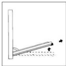
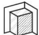
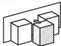
Disassembling/assembling the oven door
To make it easier to clean the inside of your oven, the oven door can be removed, by proceeding as follows (fig. 2-3):
- Open the door completely and lift the 2 levers "B" (fig. 2);
- Now, shutting the door slightly, you can lift it out by pulling out the hooks "A" as shown in figure 3.
Toreassemble the door:
- With the door in a vertical position, insert the two hooks "A" into the slots;
- Ensure that seat "D" is hooked perfectly onto the edge of the slot (move the oven door backwards and forward slightly);
- Keep the oven door open fully, unhook the 2 levers "B" downwards and then shut the door again.
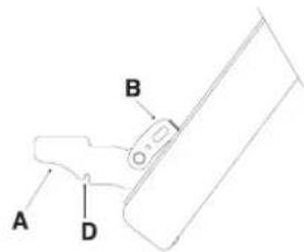
FIGURA 2
natural_image
Simple line drawing of a vertical support structure with arrows indicating direction (no text or symbols)FIGURA 3
natural_image
Pure technical line drawing of a mechanical joint or connector (no text or symbols)| Selector knob setting | Food to be cooked Weight | (in kg) | Cooking rack position from oven bottom | Preheating time (minutes) | Thermostat knob setting | Cooking time (minutes) |
| Oven | Lasagne | 2,5 | 3 | 10 | 200 | 55-60 |
| Cannelloni | 2,5 | 3 | 10 | 200 | 40-45 | |
| Pasta bakes | 2,2 | 3 | 10 | 200 | 50-55 | |
| Veal | 1,7 | 2 | 10 | 210 | 80-90 | |
| Chicken | 1,5 | 3 | 10 | 200 | 70-80 | |
| Turkey rol | 2,5 | 3 | 10 | 200 | 80-90 | |
| Duck | 1,8 | 3 | 10 | 200 | 90-100 | |
| Rabbit | 2,0 | 3 | 10 | 200 | 80-90 | |
| Pork loin | 1,5 | 3 | 10 | 200 | 70-80 | |
| Leg of lamb | 1,8 | 3 | 10 | 200 | 80-90 | |
| Mackerels | 1,3 | 3 | 10 | 200 | 30-40 | |
| Dentex | 1,5 | 3 | 10 | 180 | 30-40 | |
| Trout baked in foil | 1,0 | 3 | 10 | 200 | 30-35 | |
| Neapolitan-style pizza | 0,6 | 3 | 15 | 210 | 15-20 | |
| Dry biscuits | 0,5 | 4 | 15 | 180 | 25-30 | |
| Tart | 1,1 | 3 | 15 | 180 | 30-35 | |
| Chocolate cake | 1,0 | 3 | 15 | 165 | 50-60 | |
| Leavened cakes | 1,0 | 4 | 15 | 165 | 50-60 | |
| Grill | Soles and cuttlefish | 1 | 4 | 5 | - | 6 |
| Squid and prawn kebabs | 1 | 4 | 3 | - | 4 | |
| Cod filet | 1 | 4 | 3 | - | 10 | |
| Grilled vegetables | 1 | 4 | - | - | 8-10 | |
| Veal steak | 1 | 4 | 5 | - | 20-25 | |
| Chops | 1,5 | 4 | 5 | - | 20-25 | |
| Hamburgers | 1 | 4 | 3 | - | 10-15 | |
| Sausages | 1,7 | 4 | 5 | - | 20-25 | |
| Toasted sandwiches | n.° 4 | 4 | 3 | - | 2-3 | |
| With rotisserie (where present) | ||||||
| Veal on the spit | 1.0 | - | - | - | 80-90 | |
| Chicken on the spit | 1.5 | - | - | - | 80-90 | |
| Lamb on the spit | 1.0 | - | - | - | 80-90 |
N.B.: cooking times are approximate and may vary according to personal taste. When cooking using the grill, the dripping pan must always be placed on the 1st oven rack from the bottom.
The following instructions are provided for qualified installers so that they may accomplish installation, adjustment and technical maintenance operations correctly and in compliance with the applicable norms in force.
Important: the appliance should be disconnected from the mains electricity supply before any adjustment, maintenance, etc. is carried out. Maximum caution should be used should it be necessary to keep the appliance connected to the electricity supply. The cookers have the following technical specifications:
- Cat. III 1a2H3B/P
Class 1
Class 2 sub-class 1
The dimensions of the appliance are given in the figure on page 2. For trouble-free operation of appliances installed in furniture cabinets, the minimum distances shown in fig. 4 should be observed. Adjacent surfaces and the wall at the rear should also be able to withstand an overheating temperature of 65 °C.
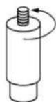
fig.5
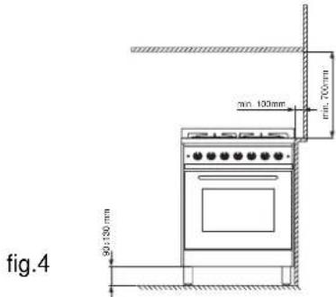
Prior to installing the cooker, the 90 ÷ 130 mm high supporting feet (provided) should be fitted into the holes to be underneath the cooker (fig. 5). These feet are screw-adjustable and whenever necessary should be used to make sure the cooker is level.
Positioning
This appliance may only be installed and operated in permanently ventilated rooms in compliance with the provisions set forth in normsin force. The following requirements must be observed:
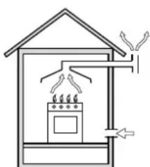
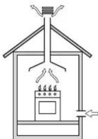
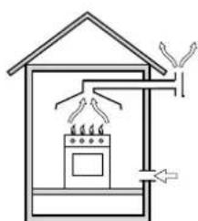
- The appliance must vent flue gases into a special hood, which must be connected to a chimney, flue pipe or directly to the outside (fig. 6).
- If it is impossible to fit a hood, the use of an electric fan is permitted, either installed on a window or on an external wall, which must be switched on at the same time as the appliance.
natural_image
Simple line drawing of a house interior with a stove and roof, no text or symbols present.fig.6
natural_image
Simple line drawing of a house interior with a stove and air duct (no text or symbols)In a chimney stack or branched flue Directly to the outside (reserved for cooking appliances)
Kitchen ventilation
The air flow into the room where the appliance is installed must equal the quantity of air that is required for regular combustion of the gas and for ventilating the same room. Air must enter naturally through permanent apertures made in the outside walls of the room or through single or branching collective ventilation ducts in compliance with the norms. The air must be taken directly from the outside, from an area far from sources of pollution. The ventilation aperture must have the following characteristics (fig. 7A):
- total free cross section of passage of at least 6cm^2 for every kW of rated heating capacity of the appliance, with a minimum of 100cm^2 (the heating capacity is indicated on the rating plate);
- it must be made in such a way that the aperture, both on the inside and outside of the wall, cannot be obstructed;
- it must be protected, e.g. with grates, wire mesh, etc. in such a way that the above-mentioned free section is not reduced;
- it must be situated as near to floor level as possible.
Detail A Adjacent Room to be
room ventilated
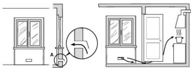
Examples of ventilation Enlarging the ventilation slot holes for comburant air between window and floor
fig. 7A fig.7B
The air inflow may also be obtained from an adjoining room, provided the latter is not a bedroom or a room where there is a risk of fire, such as warehouses, garages, fuel stores, etc. and is ventilated in compliance with the norms. The air flow from the adjoining room to the one to be ventilated may pass freely through permanent apertures with a cross section at least equal to that indicated above. These apertures may also be obtained by increasing the gap between the door and the floor (fig. 7B). If an electric fan is used for extracting the combustion products, the ventilation aperture must be increased in relation to its maximum performance. The electric fan should have a sufficient capacity to guarantee an hourly exchange of air equal to 3 ÷ 5 times the volume of the kitchen. Prolonged, intensive use of the appliance may require extra ventilation, e.g. an open window or a more efficient ventilation system by increasing the extraction power of the electric fan if installed. Liquid petroleum gas descends towards the floor as it is heavier than air. Apertures in the outside walls in rooms containing LPG cylinders should therefore be at floor level, in order to allow any gas from leaks to be expelled. Do not store LPG cylinders (even when empty) in basements or rooms below ground level; it is advisable to keep only the cylinder in use in the room at any one time and connected far from heat sources which could raise its temperature to above 50 °C.
Gas supply
- Check that the appliance is set for the type of gas available and then connect it to the mains gas piping or the gas cylinder in compliance with the applicable norms in force.
- This appliance is designed and set to work with the gas indicated on the label situated on the actual hob. If the gas supply is different from the type for which the appliance has been set, replace the corresponding nozzles (provided), following the instructions given in the paragraph "Adaptation to different types of gas".
- For trouble-free operation, suitable use of energy and a longer life cycle for the appliance, make sure that the supply pressure complies with the values indicated in table 1 "Burner and nozzle specifications", otherwise install a special pressure regulator on the supply pipe in compliance with current standards and regulations.
- Connect in such a way that the appliance is subjected to no strain whatsoever.
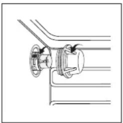
Either a rigid metal pipe with fittings (fig. 8-D) in compliance with norms must be used for connecting to the nipple union (threaded - cylindrical 1/2 "G fitting "F") situated at the rear of the appliance (fig. 8), or a flexible steel pipe with a continuous wall and fittings (fig. 8-C) in compliance with norms, which must not exceed 2000 mm in length. Check that the connecting pipe cannot come into contact with moving parts which could damage or crush it. For installation with a flexible rubber pipe, apply the special hose support for liquid gas (fig. 8-A) or natural gas (fig. 8-B). The gasket "G" (provided) must be utilised in every type of connection. The two ends of the pipe must be fastened with the purpose designed pipe collars "E", in compliance with the norms. The flexible pipe should comply with the norms, and be specific for the type of gas used. In addition:
- it should be as short as possible, with a maximum length of 1.5 metres;
- it should not be bent or kinked;
- it should not be in contact with the rear panel of the appliance or in any case with parts which may reach a temperature of 50^ ;
- it should not pass through holes or slits used for discharging the oven flue gases;
- it should not come into contact with pointed parts or sharp corners;
- it should be easy to inspect along its entire length in order to be able to check its condition;
- it should be replaced before the date printed on the actual pipe.
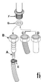
fig.8
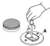
fig.9
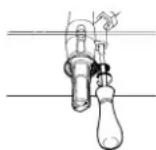
fig.10
Important: A pressure regulator, in compliance with the applicable norm in force, must be inserted when connecting to a liquid gas supply (in a cylinder).
Upon completion of installation, check for leaks from the gas circuit using a soapy solution (never use a flame). Make sure that the natural gas pipe is adequate for a sufficient supply to the appliance when all the burners are lit.
Adapting to different types of gas
To adapt the hob to a different type of gas from the factory-set one (indicated on the rating plate at the top of the hood or on the packaging), the burner nozzles should be replaced as follows:
- Remove the hob grids and slide the burners off their seats.
- Unscrew the nozzles (fig. 9), using a 7 mm socket spanner and replace them with nozzles for the new type of gas (see table 1 "Burner and nozzle characteristics").
Reassemble the parts following the above procedure in the reverse order. - On completing the operation, replace the old rating label with the one showing the new type of gas; the sticker is available from our Service Centres.
Adjusting the primary air of the burners
The primary air of the burners does not need to be adjusted.
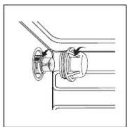
Adjusting the low flame
- Turn the tap to the low flame position;
- Remove the knob and turn the adjusting screw, situated to the right of the tap (fig. 10) until you obtain a regular small flame, using a screwdriver (loosening the screw increases the height of the flame, tightening decreases it).
N.B.: In the case of liquid gas, the regulation screw must be screwed in all the way.
- Having obtained the low flame setting required and with the burner lit, abruptly change the position of the knob several times from minimum to maximum and vice versa and check that the flame does not go out.
- In appliances fitted with the safety device (thermocouple), should the device fail to work with the burners set to the low flame setting, increase the low flame setting of the same on the adjusting screw.
Once the adjustment has been made, remount the seals on the by-passes using sealing wax or similar.
ELECTRICAL CONNECTION
Those ovens equipped with a three-pole power supply cable are designed to operate with an alternating current with the voltage and frequency indicated on the data plate (located on the appliance) and in the instruction booklet. The wire for earthing the appliance is yellow-green in colour.
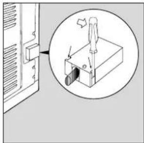
Fitting on a power supply cable
Opening the terminal board:
- Using a screwdriver, prise on the side tabs of the terminal board cover;
- Pull open the cover of the terminal board.
To install the cable, proceed as follows: - Remove the wire clamp screw and the three contact screws L-N-
- Fasten the wires beneath the screwheads using the following colour scheme: Blue (N) Brown (L) Yellow-Green
- Secure the supply cable in place with the clamp and close the cover of the terminal board.
Connecting the supply cable to the mains
Install a standardised plug corresponding to the load indicated on the data plate. When connecting the cable directly to the mains, install an omnipolar circuit-breaker with a minimum contact opening of 3 mm between the appliance and the mains. The omnipolar circuit breaker should be sized according to the load and should comply with current regulations (the earth wire should not be interrupted by the circuit breaker).
The supply cable must be in such a position that no part of it can reach a temperature of 50^ C above room temperature.
Before connecting to the power supply, make sure that:
- The electrical safety of this appliance can only be guar-
natural_image
Diagram showing a device with a screwdriver inserted into a housing, with an inset magnified view of the component (no text or symbols present)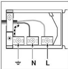
anteed if the cooker is correctly and efficiently earthed, in compliance with regulations on electrical safety. Always ensure that the earthing is efficient; if you have any doubts call in a qualified technician to check the system. The manufacturer denies all responsibility for damage resulting from a system which has not been earthed.
- Before plugging the appliance into the mains, check that the specifications indicated on the date plate (on the appliance and/or packaging) correspond to those of the electrical and gas mains of your home.
- Check that the electrical capacity of the system and sockets will support the maximum power of the appliance, as indicated on the data plate. If in doubt, consult a qualified technical engineer.
- If the socket and appliance plug are not compatible, have the socket replaced with a suitable model by a qualified technical engineer. The latter, in particular, will also have to ensure that the cross section of the socket cables are suitable for the power absorbed by the appliance. The use of adapters, multiple sockets and/or extensions, is not recommended. If their use cannot be avoided, remember to use only single or multiple adapters and extensions which comply with current safety regulations. In these cases, never exceed the maximum current capacity indicated on the single adapter or extension and the maximum power indicated on the multiple adapter. The plug and socket must be easily accessible.
BURNER AND NOZZLE SPECIFICATIONS
| Table 1 Liquid Gas Natural Gas | City Gas | |||||||||
| Burner Diameter | (mm) | Thermal Power kW (p.c.s.*) | By-pass 1/100 (mm) G30/3 | Nozzle 1/100 (mm) | Flow* g/h | Nozzler 1/100 | Flow* l/h | Nozzler 1/100 (mm) | Flow* l/h G110 | |
| Nom. | Red. (mm) | |||||||||
| Fast (Large) (R) | 100 | 3.00 | 0.7 | 40 | 86 | 218 | 116 | 286 | 260 | 680 |
| Semi Fast (Medium) (S) | 75 | 1.65 | 0.4 | 30 | 64 | 120 | 96 | 157 | 185 | 395 |
| Auxiliary (Small) (A) | 55 | 1.00 | 0.3 | 27 | 50 | 73 | 71 | 95 | 145 | 227 |
| Triple Crown (TC) | 130 | 3.25 | 1.3 | 57 | 91 | 236 | 124 | 309 | 285 | 770 |
| Supply pressures | Nominal (mbar)Minimum (mbar)Maximum (mbar) | 28-302035 | 201725 | 8615 | ||||||
* At 15°C and 1013 mbar-dry gas
G31 P.C.S. = 50.37 MJ/Kg
G30 P.C.S. = 49.47 MJ/Kg
G20 P.C.S. = 37.78 MJ/m3
G110 P.C.S. = 15.87 MJ/m3
OVEN TECHNICAL SPECIFICATIONS
ENERGY LABEL
Directive 2002/40/EC on the label of electric ovens
Norm EN 50304
Energy consumption for Natural convection:
heating mode: Convectional
Declared energy consumption for Forced convection Class:
heating mode: East cooking
Inner Volume of the ELECTRIC Oven:
53 litres
Voltage and Frequency of Power Supply:
230V \~ 50Hz 2850W
- Ovnen "Fast cooking"
- WARNINGS
- THESE INSTRUCTIONS ARE ONLY VALID FOR THE COUNTRIES OF DESTINATION WHOSE SYMBOLS ARE SHOWN IN THE BOOKLET AND ON THE APPLIANCE RATING PLATE.
- This appliance conforms to the following European Economic Community directives:
- Disposal of old electrical appliances
- HOB OPERATION
- Important:
- Using the burners:
- TIMER
- Operation with cooking time programming
- Cooling ventilation
- Convectional Mode
- Baking Mode
- "Fast cooking" Mode
- Multi-cooking Mode
- Pizza Mode
- Grill
- CLEANING AND CARE
- Before cleaning your oven, or performing maintenance, disconnect it from the power supply.
- Replacing the Lamp in the Oven
- Disassembling/assembling the oven door
- Toreassemble the door:
- Positioning
- Kitchen ventilation
- Gas supply
- Adapting to different types of gas
- Adjusting the primary air of the burners
- Adjusting the low flame
- N.B.: In the case of liquid gas, the regulation screw must be screwed in all the way.
- ELECTRICAL CONNECTION
- Fitting on a power supply cable
- Connecting the supply cable to the mains
- OVEN TECHNICAL SPECIFICATIONS
- ENERGY LABEL
Brand : INDESIT
Model : KP 648 MS (X)/DK
Category : Cooker