
Protect 9761 - Alarm OLYMPIA - Free user manual and instructions
Find the device manual for free Protect 9761 OLYMPIA in PDF.


| Product Type | Wireless Alarm System |
| Brand | Olympia |
| Model | Protect 9761 |
| Dimensions (Base Unit) | 172 x 105 x 31 mm |
| Weight (Base Unit, without batteries) | 228 g |
| Power Supply | 230 V, 50/60 Hz, 200 mA (input); 5 V, 1200 mA (output) via power adapter |
| Battery Backup | 3 x AAA alkaline batteries (1.5 V) for base unit; 1 x CR2032 for remote control |
| Radio Frequency | 868.5 MHz (sensors and remote control) |
| GSM Frequency | 800 / 900 / 1800 / 1900 MHz |
| Maximum Transmission Power | Radio: 25 mW; GSM: 3.2 W |
| Maximum Number of Sensors | 32 |
| Display | LCD with backlight, shows time, date, status icons, and text |
| Keypad | Digit keys, function keys, SOS key, panic key |
| Alarm Modes | Alarm, At Home, Silent, Disarmed, Panic, Emergency Call (SOS) |
| Telephone Unit | GSM module for alarm notifications and remote access via phone |
| Voice Messages | Recordable individual messages for each sensor |
| Programming | Menu-driven via base unit or remote control; up to 10 alarm call numbers, 1 SOS number |
| Operating Temperature | -10°C to +40°C |
| Relative Humidity | 30% to 75% |
| Cleaning | Disconnect power; clean with soft, lint-free cloth; no chemicals |
| Safety | Key lock, entry code, automatic key lock delay, child safety (suffocation/explosion warnings) |
| Scope of Delivery | Base unit, power adapter, remote control, 3 x AAA batteries, 1 x CR2032 battery, assembly material, operating manual |
Frequently Asked Questions - Protect 9761 OLYMPIA
User questions about Protect 9761 OLYMPIA
0 question about this device. Answer the ones you know or ask your own.
Ask a new question about this device
Download the instructions for your Alarm in PDF format for free! Find your manual Protect 9761 - OLYMPIA and take your electronic device back in hand. On this page are published all the documents necessary for the use of your device. Protect 9761 by OLYMPIA.
USER MANUAL Protect 9761 OLYMPIA

natural_image
Solid dark gray rectangular shape with a white diagonal line on the right edge (no text or symbols)Hello,
We are delighted that you have decided to purchase this reliable device from Olympia.
The descriptions on the following pages will explain how easy it is to make your home more safe and secure.

Content
Before You Start 6
Safety Instructions....7
Intended Use 9
Scope of Delivery 9
Overview of Base Unit 10
Front 10
Rear 11
Display 12
Keys and Operating Elements ..... 13
Control Lamps 14
Overview of Remote Control ..... 14
Menu Structure 15
Putting the Base Unit into Operation ... 16
Positioning the Base Unit 16
Inserting the SIM Card (Option) ..... 17
Inserting the Batteries (Option) ..... 18
Connecting the Power Adapter ..... 19
Setting Up the Base Unit .... 20
Setting the Key Lock 20
Setting the Language 21
Setting the Time and Date 21
Registering Sensors 22
Deregistering Sensors 23
Renaming Sensors 23
Individual Voice Message 23
Configuring the Telephone Unit ..... 24
Saving Alarm Call Numbers....25
Saving an SOS (Emergency Call) Number .. 26
Testing the Telephone Unit 26
Setting the Trigger Delay 27
Setting the Arming Delay 28
Setting the Alarm Period 28
Switching the Warning Signal from the Base Unit On/Off 28
Setting the Key Tone 29
Setting the Volume of the Voice Output . . . 29
Setting the Contrast 29

Monitoring Functions .... 30
Alarm Mode 31
At Home Mode 31
Silent Mode 32
Disarmed Mode 32
Panic Alarm 33
Emergency Call (SOS) 33
PIR At Home Mode 34
Smoke and Water Detectors 35
Function of the ⑤Key 35
Remote Access by Phone 36
Appendix 37
Restoring the Default Factory Settings .... 37
Changing the Battery 37
System Extensions.... 37
Technical Data - Base Unit. 38
Technical Data - Remote Control ..... 38
Cleaning and Service 38
Information on Disposal 39
Guarantee 39
Information on Conformity 39

BEFORE YOU START
Before You Start
The alarm system is a passive security product and has been conceived as a deterrent. Additional measures are necessary to prevent and hinder burglary and theft.
You can obtain all the necessary information on this from your local police station.
You can increase security by integrating additional sensors from the Olympia range. We also provide outdoor sirens, door/window contacts, motion detectors, vibration sensors, water detectors, glass breakage detectors and much more.
You can find more information on securing your home on our website: www.olympia-vertrieb.de

Read the operating manual thoroughly and observe all the information contained when using the alarm system. Keep the operating manual in a safe place for future reference.

Pay attention to this symbol. Texts which are highlighted by this symbol provide helpful information on handling the alarm system.
Safety Instructions
The following warnings apply to the entire document. Read and observe all the warning information to protect yourself and the environment from any harm.
The following warnings indicate potentially dangerous situations which could lead to serious injuries or even fatal injuries if the information is ignored.

WARNING!
Risk of fatal injury from electric shock! NEVER use the device if you suspect damage to the power cable or power plug or there are visible signs of damage to the power cable or power plug.

NEVER complete any repairs to the device yourself. Never open the device because it contains no components which you may service yourself. In the event of a fault, contact our Service Department.

WARNING!
Risk of suffocation! Children can swallow small parts, packaging and protective foils. Keep the device and packaging out of reach of children.

WARNING!
Risks to health through batteries! Keep batteries out of reach of children. Do not swallow batteries. If any type of battery or round cell is swallowed, seek medical attention immediately.

WARNING!
Risk of explosion! Improper storage of batteries can put your health and the environment at risk. Batteries may contain toxic, ecologically hazardous heavy metals. Never open, damage or swallow batteries or allow them to pollute the environment.

SAFETY INSTRUCTIONS
The following warnings indicate potentially dangerous situations which could lead to minor or slight injuries if the information is ignored.

CAUTION!
This device can be used by children from the age of 8 and persons with restricted physical, sensory or mental capabilities or a lack of experience and knowledge as long as they are supervised or have been instructed with regard to safe use of the device and are aware of the potential risks involved with its use. Children must never play with the device. Cleaning and user maintenance may not be completed by children without any supervision.

CAUTION!
Hearing damage through loud alarm signal! Due to legal requirements, the alarm signal continues for maximally 120 seconds. The alarm signal switches off automatically after about 120 seconds if the user does not interrupt it. Use ear protectors when testing the device. Do not remain in the vicinity of the acoustic alarm for a longer period when it has been triggered.
The following warnings indicate potentially dangerous situations which could lead to property damage if the information is ignored.

ATTENTION!
Property damage through the use of inappropriate batteries! The use of inappropriate batteries can cause a loss of function of the device. Only use batteries of the type described in Section "Technical Data".

ATTENTION!
Property damage through environmental influences! Prevent environmental influences such as exposure to smoke, dust, vibration, chemicals, moisture, heat and direct sunlight.
Intended Use
The alarm system in the Protect Series is suitable for monitoring rooms and houses, as long as there is a reliable wireless connection to the registered sensors (e.g. door/window contacts, smoke detector).
A condition for complying with the intended use is that the equipment is installed correctly and the information in the manual is observed and maintained.
Any other use is considered unintended use.
This operating instruction manual contains important information on setting up and handling the equipment. Always hand over this operating manual if the alarm system is transferred to others.
Scope of Delivery
Please check the contents of the package carefully. If anything is missing or has been damaged during transport, DO NOT put the alarm system into operation! Keep the packaging in a safe place to protect the equipment from damage should it need to be dispatched in future.
Base unit
Power adapter
Remote control
Batteries 3 x alkaline batteries, AAA, 1.5 V
1 x round cell battery, CR2032
Assembly material Base unit legs, screws, dowels
Operating manual

OVERVIEW OF BASE UNIT
Overview of Base Unit
Front
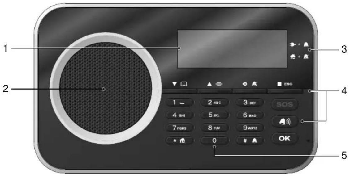
1 Display 4 Function keys
2 Loudspeaker 5 Digit keys
3 Control lamps
Rear
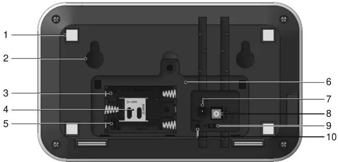
1 Rubberised base unit legs 6 Battery compartment cover
| 2 | Recesses for mounting bracket | 7 | Connection port for power adapter |
| 3 | Battery compartment | 8 | Connection for external antenna (option) |
| 4 | Compartment for SIM card 9 Antenna switch | ||
| 5 | MicroUSB connection port | 10 | Reset key |

OVERVIEW OF BASE UNIT
Display
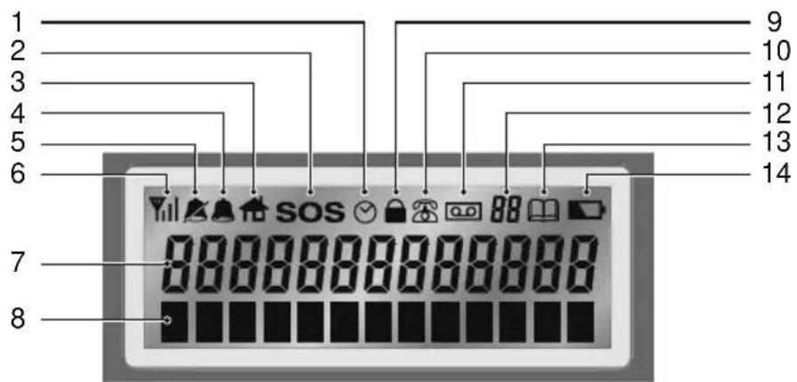
| 1 | Delay activated (arming, triggering, key lock) | 8 | More information in plain text (e.g. Register) |
| 2 | Telephone unit activated for emergency call (SOS) | 9 | Key lock activated |
| 3 | At Home mode activated | 10 | Telephone unit activated |
| 4 | Alarm mode activated | 11 | Recorded message playing |
| 5 | Silent mode activated | 12 | Storage location of phone number |
| 6 | Display of the network availability | 13 | Save icon |
| 7 | Display for plain text (e.g. 19:09) | 14 | Base unit battery is almost empty |
Keys and Operating Elements
The following table indicates the functions assigned to the individual keys and operating elements on the front of the base unit of the alarm system.
sos SOS key
OK Confirm entries
Panic key
Open the menu; navigate in the menu; increase the loudspeaker volume in Hands-free mode
Open Save mode for alarm phone numbers; navigate in the menu; reduce the loudspeaker volume in Handsfree mode
■ ESC Disarmed mode key; exit the menu; stop the countdown
Silent mode key; delete input
# Alarm mode key
* At Home mode key
0 Digit keys to enter your settings

OVERVIEW OF REMOTE CONTROL
Control Lamps
The following table indicates the flashing and light-up behaviour of the control lamps on the front of the base unit of the alarm system.
| Operation via power adapter | |
| Top LED Bottom LED | |
| Silent mode Lights up Flashing | |
| Alarm mode Flashing Off | |
| At Home mode Lights up Lights up | |
| Disarmed mode Lights up Off |
| Operation with batteries | ||
| Top LED Bottom LED | ||
| Silent mode Off | Flashing | |
| Alarm Mode | Flashing Off | |
| At Home Mode | Off Lights up | |
| Disarmed Mode | Off Off | |
Overview of Remote Control
The remote control enables you to switch monitoring functions on and off, trigger a Panic alarm or make an emergency call via the base unit of the alarm system.
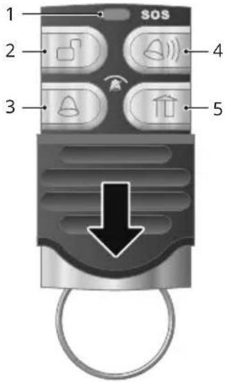
1 Lamp indicator
2 Disarm key
3 Alarm key
4 Panic key / Emergency call key
5 At Home key
Menu Structure
▲ ≡ (Open the menu)
| Review | ||
| Register | ||
| Entry Code | ||
| KeyLock Delay | ||
| Date/Time | ||
| Check SIM $ | ||
| Alarm Setup Trigger Delay | ||
| Trigger Tone On | ||
| Off | ||
| Arming Delay | ||
| Alarm Period | ||
| Voice Message High | ||
| Low | ||
| Off | ||
| Base alarm On | ||
| Off | ||
| Device Setup Smoke & Flood Standard | ||
| Always on | ||
| PIR Home Mode On | ||
| Off | ||
| Remote control | ||
| Display&Tone Key | Tone High | |
| Low | ||
| Off | ||
| Contrast | ||
| Language | ||
The adjacent menu structure indicates the predefined language, namely German.
If you want to set another language, follow the operating sequence in the menu structure.
More detailed information on operating and navigating in the base unit is provided in Section Setting Up the Base Unit on Page 20.

PUTTING THE BASE UNIT INTO OPERATION
Putting the Base Unit into Operation
This section explains how to position the alarm system or mount it on a wall optimally, insert the batteries and SIM card and supply power to the alarm system.
Positioning the Base Unit
Set the base unit down on a level, non-slip surface.

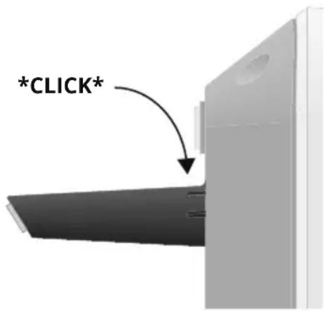
To ensure even more operating convenience, we recommend that you install the legs supplied to the underside of the base unit. The base unit legs latch in place audibly.
- Do not place the base unit on or in the direct vicinity of large metallic objects or electrical sources of interference which could impair the wireless communication.
- Position the base unit as centrally as possible in the area to be monitored to ensure optimum radio transmission of all components.
- You can install the base unit on a wall. To do this, screw two screws in the wall, 100 mm apart and horizontally aligned, and hook the heads of the screws in the recesses on the rear of base unit.
Inserting the SIM Card (Option)

If you don't want to use a SIM card, you can skip this chapter.
If you want to be notified on your mobile phone in the event of an alarm being triggered, you need a commercially available SIM card. Insert the SIM card in the base unit as described below.
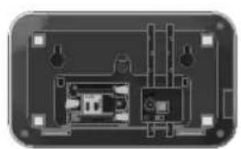
1 Slide the SIM card holder to the side to unlock the holder.
2 Pivot the holder up and insert the SIM card in the holder.
The metallic contacts of the SIM card must face down.
3 Pivot the holder downwards and slide the holder to the side to lock it.

Please note that contractually linked costs may ensue when the telephone unit establishes connections to saved numbers via the SIM card.

If you use an external antenna, set the switch on the antenna to Ext..
natural_image
Interior view of a device module with visible circuitry and components (no text or symbols)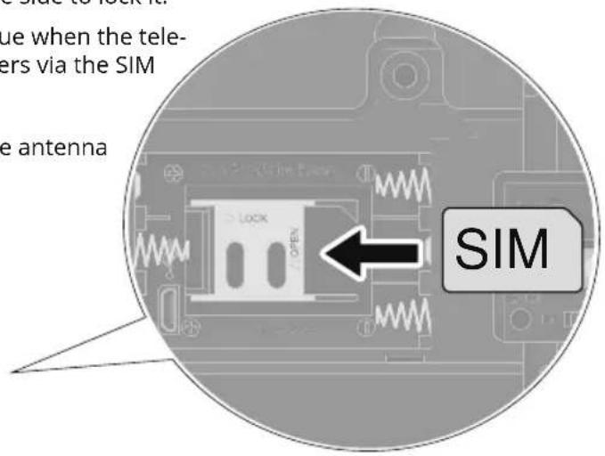

PUTTING THE BASE UNIT INTO OPERATION
Inserting the Batteries (Option)
The use of batteries serves as a safeguard against power failure. In the case of normal power supply using the power adapter, the batteries are not affected. In the event of a power failure, power is supplied to the base unit by the batteries until the power supply returns or the batteries are empty.

ATTENTION! Risk of property damage through the use of inappropriate batteries! The use of inappropriate batteries can cause a loss of function of the device. Only use the batteries supplied or those of the type described in Section "Technical Data".
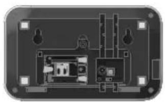
1 Loosen the screw in the battery compartment cover using an appropriate screwdriver.
2 Remove the battery compartment cover.
3 Insert three appropriate batteries in the battery compartment. Pay attention that the batteries are inserted the right way around.
4 Replace the battery compartment cover and tighten the screw in the battery compartment cover tight.
natural_image
Interior view of a device casing showing internal components and mounting holes (no text or symbols visible)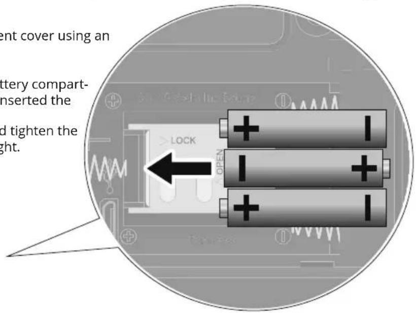
Connecting the Power Adapter
Power is supplied to the base unit of the alarm system via the power adapter. To ensure an uninterrupted power supply, you can insert the optionally available batteries the base unit (see Section Inserting the Batteries (Option) on Page 18).
1 Loosen the screw in the battery compartment cover using an appropriate screwdriver.
2 Remove the battery compartment cover.
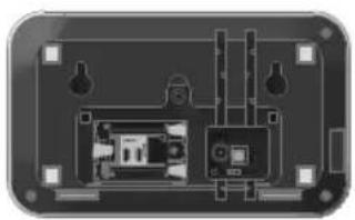
3 Plug the power adapter in the connection socket for the power adapter on the underside of the base unit.
4 Replace the battery compartment cover and tighten the screw in the battery compartment cover tight.
5 Plug the power adapter in a properly installed power socket.

If you want to insert a SIM card or batteries in the base unit, refer to the sections "Inserting a SIM Card (Option)" and "Inserting the Batteries (Option)" before closing the battery compartment.

Use the cable duct to lay the power cable on the underside of the base unit.
natural_image
Interior view of a device module with visible circuitry and components (no text or symbols)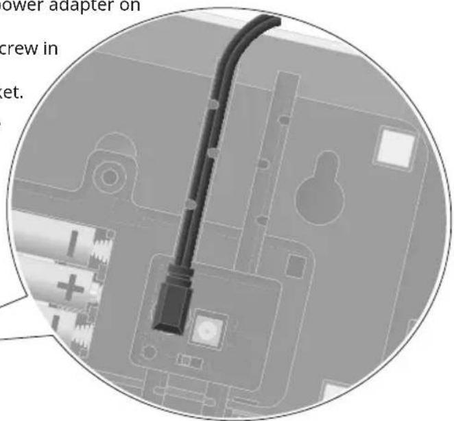

SETTING UP THE BASE UNIT
Setting Up the Base Unit
This section explains how to adapt the base unit of the alarm system to your own personal needs.
Also observe the information in the operating manual with regard to the individual sensors which you want to connect to the base unit of the alarm system.
Setting the Key Lock
Before beginning to operate the base unit, deactivate the key lock function.

The SOS and Panic keys are excluded from the key lock function and are always functional!
Entry Code
The base unit is protected by means of a four-digit entry code in order to prevent access to the base unit by unauthorised third parties.
The predefined entry code is active when the factory settings are set. The predefined entry code is provided in the battery compartment of the base unit and on the rear side of this operating manual.

For reasons of security, we recommend that you change the predefined entry code by your own personal entry code.
1 Select the Entry Code menu option.
2 Confirm by pressing OK. The predefined entry code appears in the display. The first digit flashes.
3 Enter your own personal, 4-digit entry code.
4 Confirm by pressing OK.
5 Note down your new entry code and keep it where it cannot be accessed by third-parties.
Deactivating the Key Lock
1 Enter your personal entry code.
2 Confirm by pressing OK.

When using the remote control, deactivate the key lock by pressing the ☐ key.
Setting the Automatic Key Lock
You can define a period of time after which the key lock is automatically activated.
You can set a delay of between 20 and 40 seconds.
1 Select the KeyLock Delay menu option.
2 Confirm by pressing OK.
3 Set the required delay time.
4 Confirm by pressing OK.
Setting the Language
There is a range of languages available for selection:
1 Select the Display&Tone menu option.
2 Confirm by pressing OK.
3 Select the Language menu option.
4 Confirm by pressing OK.
5 Select the required language. Confirm by pressing OK.
Setting the Time and Date
The standard display which appears on the base unit shows the date and time. Therefore, set the current date and time.
1 Select the Date/Time menu option.
2 Confirm by pressing OK. 01-01-2017 appears in the display.
3 Enter the day, month and year. Confirm by pressing OK. 00:00 appears in the display.
4 Enter the time as hour and minute. Confirm by pressing OK.

SETTING UP THE BASE UNIT
Registering Sensors
You can register up to 32 sensors on the alarm system base unit.
1 Select the Register menu option.
2 Confirm by pressing OK. Search... appears in the display.
3 Trigger the sensor to be registered.

The way to trigger the individual sensors is explained in the Sensors for the Protect Series operating manual. This manual is enclosed with the base unit.
4 The display shows the name of the active sensor e.g. Remote Key.
5 Confirm by pressing OK. Voice Record appears in the display. You can either use the standard message or record an individual voice message.
In the following descriptions, you can use either an individually recorded voice message or standard message for the registered sensor. The individually recorded voice messages can be recorded or modified at a later point in time.
When the corresponding sensor is triggered, the related voice message is played over the loudspeaker of the base unit.
6 Press ■ ESC if you want to retain the standard message of the registered sensor.
7 Press OK to record an individual voice message.

Further information is available in Section Individual Voice Message on Page 23.
Deregistering Sensors
If a sensor is no longer required, you can deregister that sensor from the base unit.
1 Select the Review menu option.
2 Select the sensor you wish to deregister.
3 Press the Ⓧ key. Delete? appears in the display.
4 Confirm by pressing (OK).
Renaming Sensors
You can rename any of the registered sensors in order to adapt it to your own individual needs.
1 Select the Review menu option.
2 Confirm by pressing OK.
3 Select the required sensor.
4 Confirm by pressing OK.
5 Press the ✕ ↗ key to delete the sensor name.
6 Enter a name for the sensor.
7 Confirm by pressing OK.
8 Press the ■ESC key.
Individual Voice Message
An individual outgoing voice message can be recorded for each sensor (door/window contact, smoke detector, etc.). The standard message is replaced by your individual voice message and played when the telephone unit is activated.
1 Select the Review menu option.
2 Confirm by pressing OK.
3 Select the required sensor.
4 Confirm by pressing OK.
5 The cursor flashes at the end of the sensor name. You can rename the sensor (see Section Renaming Sensors on Page 23).
6 Confirm by pressing OK.
/ Voice Record appears in the display. Confirm by pressing OK.
8 Speak your specific message for the selected sensor to record it.
9 Confirm by pressing OK to end the recording process. Your individual voice message is played back.

If you no longer like the voice message recorded, you can repeat the process.

SETTING UP THE BASE UNIT
Configuring the Telephone Unit
The telephone unit establishes a connection between the base unit and alarm system and the mobile communication network via an appropriate SIM card.

The SIM card is not included in the package contents.
Please note that contractually linked costs may ensue when the telephone unit establishes connections to saved numbers via the SIM card.
In the event of an alarm, the telephone unit automatically dials the alarm phone numbers stored (starting with storage location 0) in succession and provides information regarding the alarm by means of an automatic voice message. If a number dialled is "busy" or "rejected", the next phone number is automatically dialled.
The telephone unit is deactivated when
- the called person takes the call and presses the digit key [1] on their phone or
- the cycle of calls is completed 3 times.
Unlocking the SIM Card
SIM cards are normally protected against unauthorised access by a 4-digit PIN. When the SIM card is used for the first time, it must be unlocked.
1 If the SIM card is locked by a PIN, the SIM PIN? message appears in the display.
2 Enter the PIN which you received together with the SIM card.
After entering the correct PIN, Search... appears in the display. The PIN is then permanently deactivated.
3 After entering the wrong PIN, Enter Again? appears in the display. Enter the PIN again.

After entering the PIN wrongly three times, SIM Locked appears in the display. In this case, contact your mobile phone provider to release the lock.
Checking the SIM Card
Check SIM \$ appears in the display on 1st January, 1st April, 1st July and 1st October.
1 Select the Check SIM \$ menu option.
2 Confirm by pressing OK. SIM Service # appears in the display.
3 Enter the service number of the mobile phone provider.

If you require more information, please contact your mobile service provider.
4 Confirm by pressing OK. The service number is dialled.
5 Follow the instructions from the mobile phone provider.
6 End the connection by pressing OK.
Saving Alarm Call Numbers
You can save up to 10 alarm call numbers in the storage locations 0 to 9wxyz. These phone numbers are called as soon as one of the registered sensors triggers an alarm on the base unit.

Agree on procedures in the event of an alarm with these contact persons in advance.
Each phone number can be composed of up to 24 digits and the associated name up to 13 characters.

Do not save any public emergency call numbers! Unjustified requests for police, fire and rescue services are liable for costs!
1 Press ▼. Memory Keys appears in the display.
2 Select a storage location (keys 0 to 9wxyz). If you have not yet stored any phone numbers, Empty appears in the display.
3 Confirm by pressing OK.
4 Enter a name.
5 Confirm by pressing OK.
6 Enter the full phone number.
7 Confirm by pressing OK.

SETTING UP THE BASE UNIT
Saving an SOS (Emergency Call) Number
You can store an emergency call number which is dialled first of all after pressing the SOS key or SOS key on the remote control.
Following this, the other stored phone numbers are dialled in succession.

Do not save any public emergency call numbers! Unjustified requests for police, fire and rescue services are liable for costs!
1 Press ▼. Memory Keys appears in the display.
2 Select the SOS key as the required storage location. If you have not yet stored any phone numbers, Empty appears in the display.
3 Confirm by pressing OK.
4 Enter a name.
5 Confirm by pressing OK.
6 Enter the full phone number.
7 Confirm by pressing OK.
Testing the Telephone Unit
After having entered phone numbers, ensure that they are correct in respect of the response in the event of an alarm. You can trigger a silent alarm to do this.
1 Press ⚙️. Silent mode is activated.
2 Trigger the silent alarm for any sensor. The display lights up yellow and indicates which sensor has been triggered.
3 The telephone unit is activated.
- The subscriber called lifts the receiver and hears either the individual outgoing voice message or standard voice message.
Further information is provided in Section Individual Voice Message on Page 23.
- The subscriber called is also requested to press digit key [1] on their telephone. The screening function is activated and enables the subscriber to screen the room in which the base unit is located.
Setting the Trigger Delay
- The voice message is repeated a total of three times. If the subscriber does not press digit key [1] on his phone, the connection is automatically ended and the next phone number dialled.
The telephone unit and alarm are switched off:
• after pressing the 🔍 key on the remote control,
- after entering your entry code on the base unit and confirming with OK or
- when the person called ends the current connection.

The base unit is then in Silent mode.
You can set the actual alarm to be triggered after a delay. This provides you with sufficient time to enter your apartment or house and disarm the alarm system.
You can set a trigger delay between 0 and 240 seconds. You can also select whether an acoustic signal (countdown) should be issued from the base unit during this period or not.

If one of the sensors is tripped, the base unit must be disarmed within the trigger delay period to ensure no alarm is triggered.
1 Select the Alarm Setup menu option.
2 Confirm by pressing OK.
3 Select the Trigger Delay menu option.
4 Confirm by pressing OK.
5 Set the delay time.
6 Confirm by pressing OK.
7 Select the Trigger Tone menu option.
8 Confirm by pressing OK.
9 Set the trigger tone to On or Off.
10 Confirm by pressing OK.

SETTING UP THE BASE UNIT
Setting the Arming Delay
You can set the alarm system to be armed following a defined delay.
This provides you with sufficient time to leave your apartment or house through the alarm-protected front door before the alarm system is actually armed.
You can set an arming delay between 0 and 240 seconds.
During the delay period, you will hear a signal tone issued at intervals of one second.
1 Select the Alarm Setup menu option.
2 Confirm by pressing OK.
3 Select the Arming Delay menu option.
4 Confirm by pressing OK.
5 Set the delay time.
6 Confirm by pressing OK.
Setting the Alarm Period
The base unit is equipped with its own siren.
The duration of the warning signal can be selected between a minimum of 1 minute to a maximum of 10 minutes.
The standard setting for the alarm period is 1 minute.

Observe any locally applicable regulations regarding limitation of alarm times from burglar alarms.
1 Select the Alarm Setup menu option.
2 Confirm by pressing OK.
3 Select the Alarm Period menu option.
4 Confirm by pressing (OK).
5 Set the alarm period.
6 Confirm by pressing OK.
Switching the Warning Signal from the Base Unit On/Off
This function enables the warning signal from the base unit to be switched on and off.

This setting is useful, for example, if you have installed an additional outdoor siren. If an alarm is triggered, the outdoor siren issues a loud warning signal and alerts others to the situation. The base unit remains silent, making it more difficult for the intruder to find the base unit.
1 Select the Alarm Setup menu option.
2 Confirm by pressing OK.
3 Select the Base Alarm menu option.
4 Confirm by pressing OK.
5 Set the warning signal of the base unit to High, Low or Off.
6 Confirm by pressing OK.
Setting the Key Tone
It is possible to switch the key tone feature for the base unit on and off.
1 Select the Display&Tone menu option.
2 Confirm by pressing OK.
3 Select the Key Tone menu option.
4 Confirm by pressing OK.
5 Set the key tone setting to High, Low or Off.
6 Confirm by pressing OK.
Setting the Volume of the Voice Output
You can adjust the volume level of the voice output on the base unit or switch it off.
1 Select the Alarm Setup menu option.
2 Confirm by pressing OK.
3 Select the Voice Message menu option.
4 Confirm by pressing (OK).
5 Set the volume of the voice messages to High, Low or Off.
6 Confirm by pressing OK.
Setting the Contrast
You can adjust the contrast of the display to one of 5 different settings.
1 Select the Display&Tone menu option.
2 Confirm by pressing OK.
3 Select the Contrast menu option.
4 Confirm by pressing OK.
5 Set the required contrast setting using the ▲≡ and ▼ keys.
6 Confirm by pressing OK.

MONITORING FUNCTIONS
Monitoring Functions
You can adapt the alarm system according to your own personal needs. The table below provides an overview of how the base unit of your alarm system reacts to each respective monitoring function when activated.

Pay attention that, in general, the warning signal is issued by the base unit. If you have deactivated the warning signal on the base unit and there is no outdoor siren installed, the alarm system remains silent in every monitoring function!

Before switching any functions on, inform all the other people living in the residence regarding the location and method of operation of the wireless alarm system.
Monitoring function Alarm signal Telephone unit (GSM)
| Alarm mode Yes Yes | |
| At Home mode Yes No | |
| Silent mode No Yes, with screening function | |
| Disarmed mode No No | |
| Panic alarm Yes No | |
| Emergency call (SOS) No Yes, with screening function | |
| PIR At Home mode See Section PIR At Home Mode on Page 34 | |
| Smoke and water detector See Section Smoke and Water Detectors on Page 35 | |
SOS / Panic alarm (remote control)
See Section Function of the

Key on Page 35
Alarm Mode
When Alarm mode is active and an alarm is triggered, an acoustic warning signal is issued and the telephone unit is activated.
You should activate Alarm mode when you leave your apartment or house. Before doing so, check that all the doors and windows provided with a door/window contact are closed.
You can switch the mode on and off either using the base unit or via the remote control.
1 Enter your entry code.
2 Confirm by pressing OK.
3 Press the 🔊 key.

To activate Alarm mode via the remote control, press the ■ key.
At Home Mode
When At Home mode is active and an alarm is triggered, only an acoustic alarm signal is issued.
It is recommended to activate At Home mode during the night. Before doing so, check that all the doors and windows are closed.
You can switch the mode on and off either using the base unit or via the remote control.
1 Enter your entry code.
2 Confirm by pressing OK.
3 Press the * 仓 key.

To activate At Home mode via the remote control, press the 🔒 key.

MONITORING FUNCTIONS
Silent Mode
When Silent mode is active, only the telephone unit is activated. A person called receives a voice message requesting them to press the [1] key on their phone. The screening function is activated.
When you leave your apartment or house, you can activate Silent mode instead of Alarm mode. Before doing so, check that all the doors and windows provided with a door/window contact are closed.
You can switch the mode on and off either using the base unit or via the remote contro.
1 Enter your entry code.
2 Confirm by pressing OK.
3 Press the ✕ key.

To activate Silent mode via the remote control, press the ▪ and ▶ keys (simultaneously).
Disarmed Mode
When Disarmed mode is set, the alarm system is deactivated.
When the system is disarmed, you can move freely within the living quarters without triggering any alarms.
You can switch the mode on and off either using the base unit or via the remote control.
1 Enter your entry code.
2 Confirm by pressing OK

To activate Disarmed mode via the remote control, press the ☐ key.
Panic Alarm
The Panic alarm serves as a deterrent and is triggered immediately.
Triggering the Panic Alarm

Caution! Hearing damage through loud alarm signal! The panic alarm is triggered immediately without any delay. Do not remain in the vicinity of the acoustic alarm for a longer period when it has been triggered.
1 Press the 🔊 key.

You can trigger the Panic alarm via the remote control (depending on the settings) by pressing the ⑤05 key. Further information is provided in Section Function of the ⑥05 Key on Page 35.
Stopping the Panic Alarm
1 Enter your own personal, 4-digit entry code on the base unit.
2 Confirm by pressing OK.

You can stop the Panic alarm via the remote control by pressing the ☐ key.
Emergency Call (SOS)
The emergency call (SOS) can be used in a threatening situation to send for help from previously stored numbers by pressing just one key.
Triggering an Emergency Call (SOS)
1 Press the sos key.

You can trigger the emergency call (SOS) via the remote control (depending on the settings) by pressing the Ⓜkey. Further information is provided in Section Function of the ⓂKey on Page 35.
The telephone unit is activated if phone numbers are stored.
The emergency call number (SOS) is dialled first, then up to 10 stored alarm phone numbers in succession.
A voice message requests the subscriber answering to press the [1] key on their phone.
The handsfree function of the base unit is activated and enables communication between the caller and subscriber called.

MONITORING FUNCTIONS
Ending the Emergency Call (SOS)
There are three ways to end the emergency call (SOS) function.
- Enter your entry code on the base unit and confirm it by pressing OK.
- Press the 🔍 key on the remote control.
- The subscriber called takes the call, executes a function within 24 seconds and then ends the call.
PIR At Home Mode
Using the optional PIR At Home mode, the alarm activated by means of motion detectors in At Home mode are deactivated. This mode can only be activated on the base unit.
When PIR At Home mode is activated, the motion detectors registered on the base unit in At Home mode are deactivated.

This means that false alarms caused by unavoidable movements within the area monitored (by residents, pets, etc.) can be prevented.
1 Select the Device Setup menu option.
2 Confirm by pressing OK.
3 Select the PIR Home Mode menu option.
4 Confirm by pressing OK.
5 Switch PIR At Home mode On or Off.
6 Confirm by pressing OK.
Smoke and Water Detectors
You can set-up the base unit so that water leak and smoke detectors also trigger an alarm when the base unit is disarmed or in Silent mode.
1 Select the Device Setup menu option.
2 Confirm by pressing OK.
3 Select the Smoke & Flood menu option.
4 Confirm by pressing OK.
5 Select the Standard or Always on setting.
6 Confirm by pressing OK.
The table below explains how the smoke and water detectors react.
Standard Always on
GSM Alarm GSM | Alarm
| Silent mode Yes No Yes Yes |
| Alarm mode Yes Yes Yes Yes |
| At Home mode No Yes No Yes |
| Disarmed mode No No Yes Yes |
Function of the Key
You can programme how the base unit responds after pressing the Ⓞ key on the remote control.
Triggering the Panic Alarm
You can programme that a Panic alarm is triggered after pressing the ⑤02 key on the remote control.
1 Select the Device Setup menu option.
2 Confirm by pressing OK.
3 Select the Remote Key menu option.
4 Confirm by pressing OK.
5 Select the Panic option.
6 Confirm by pressing OK.
Triggering an Emergency Call (SOS)
You can programme that an emergency call (SOS) is triggered after pressing the SOS key on the remote control.
1 Select the Device Setup menu option.
2 Confirm by pressing OK.
3 Select the Remote Key menu option.
4 Confirm by pressing OK.
5 Select the SOS option.
6 Confirm by pressing OK.

REMOTE ACCESS BY PHONE
Remote Access by Phone
The wireless alarm system can be operated by remote access using a telephone.
1 Dial the phone number of the SIM card installed in the base unit.
2 Wait until the base unit takes your call. A longer acoustic signal is issued.
3 Enter the 4-digit entry code on the base unit. You will hear two short acoustic tones.
4 Complete various functions using the phone's keypad (refer to the table). The monitoring functions are confirmed by a voice message.
Key Function
1 Activate the handsfree function
2 Activate call screening
3 Activate Alarm mode
4 Activate At Home mode
5 Activate Silent mode
6 Activate Disarmed mode
# Stop the Handsfree / Call screening function
, # End remote access
Appendix
Restoring the Default Factory Settings
Please note that on restoring the factory settings, all the user settings will be deleted. The registration of the sensors is retained.
If you restore the factory settings of the base unit, the 4-digit entry code is 1234!
1 Loosen the screw in the battery compartment cover on the underside of the base unit using an appropriate screwdriver.
2 Remove any batteries which are already inserted.
3 Press the RESET key. The base unit confirms the factory settings have been restored by issuing an acoustic signal.
4 Insert three appropriate batteries in the battery compartment. Pay attention that the batteries are inserted the right way around.
5 Replace the battery compartment cover and tighten the screw in the battery compartment cover tight using an appropriate screwdriver.
Changing the Battery
If the battery charge of the sensors is low or almost fully discharged, the corresponding status message appears on the display (BATT. LOW. / BATT. OFF). Change the batteries as soon as possible in such cases to ensure a reliable connection of all the components integrated in the alarm system.
The way to change the batteries of the individual sensors is explained in the Sensors for the Protect Series manual supplied with the sensors. This manual is enclosed with the base unit.
You can also find the Sensors for the Protect Series operating manual for the sensors on our website at www.olympia-vertrieb.de
System Extensions
You can order numerous extensions for your Olympia alarm system through our website.
Technical Data - Base Unit
| Weight 228 g (without batteries) | |
| Dimensions (W x H x D) 172 x 105 x 31 [mm] | |
| Frequency (radio) 868.5 MHz | |
| Frequency (GSM) 800 / 900 / 1800 / 1900 MHz | |
| Maximum transmission power | Radio (868.5 MHz): 25 mWGSM: 3.2 W |
| Sensors Up to 32 | |
| Battery (option) 3 x alkaline batteries (AAA, 1.5 V) | |
| Power supply Input: | |
| 230 V, 50/60 Hz, 200 mAOutput:5 V, 1200 mA | |
| Permissible ambient conditions | -10 °C to +40 °C at30% to 75% rel. humidity |
Technical Data - Remote Control
| Weight Approx. 20 g | |
| Dimensions (W x H x D) 40 x 60 x 14.5 mm | |
| Radio frequency 868.5 MHz | |
| Battery 1 x round cell battery,CR2032 | |
| Maximum transmission power | 0.04 mW |
| Permissible ambient conditions | -10 °C to +40 °C at30% to 75% rel. humidity |
Cleaning and Service
1 Disconnect the base unit from the power supply before starting any cleaning work.
2 Clean the surface of the housing with a soft, lint-free cloth. Never use any chemicals or scouring agents.
3 Check the functionality of each sensor registered once a month and after changing the batteries.
4 Change the batteries at least once a year or after receiving the relevant message from the alarm system.
Information on Disposal

The adjacent symbol indicates that electrical and electronic apparatus and batteries no longer required must be disposed of separate from domestic waste in accordance with legal directives. You are legally obliged to dispose of batteries and power packs at shops which sell batteries or collection points which provide the corresponding containers. Disposal is free of charge. The symbols indicate that the batteries must not be disposed of in normal domestic waste and that they must be brought to collection points provided by local public waste authorities. Packaging materials must be disposed of according to local regulations.
Guarantee
Dear Customer,
we are pleased that you have chosen this equipment.
In the case of a defect, please return the device together with the receipt and original packing material to the point-of-sale.
Information on Conformity
CE Olympia Business Systems Vertriebs GmbH, Zum Kraftwerk 1, 45527 Hattingen hereby declares that this device fulfils the basic requirements and other relevant provisions stipulated in the Directive 2014/53/EC.
The CE mark on the device confirms its conformity. The Declaration of Conformity for this product is available at http://productip.com/?f=5d249




natural_image
Abstract geometric composition with a gray rectangle and white diagonal stripe on a dark gray background (no text or symbols)This is your individually preprogrammed entry code.
If you want to change this predefined entry code, please refer to Chapter "Configuration" in this operating manual. Keep this operating manual in a safe place away from the alarm system!
Subject to change without prior notice.
OLYMPIA
v1.1, 08.2017
Protect Serie Base Unit

- Content
- Monitoring Functions .... 30
- Remote Access by Phone 36
- Appendix 37
- BEFORE YOU START
- Safety Instructions
- WARNING!
- CAUTION!
- ATTENTION!
- Intended Use
- Scope of Delivery
- Base unit
- Power adapter
- Remote control
- Operating manual
- Overview of Base Unit
- Rear
- Keys and Operating Elements
- OVERVIEW OF REMOTE CONTROL
- Control Lamps
- Menu Structure
- PUTTING THE BASE UNIT INTO OPERATION
- Positioning the Base Unit
- Inserting the SIM Card (Option)
- Inserting the Batteries (Option)
- Connecting the Power Adapter
- SETTING UP THE BASE UNIT
- Setting the Key Lock
- Entry Code
- Deactivating the Key Lock
- Setting the Automatic Key Lock
- Setting the Language
- Setting the Time and Date
- Registering Sensors
- Deregistering Sensors
- Renaming Sensors
- Individual Voice Message
- Configuring the Telephone Unit
- Unlocking the SIM Card
- Checking the SIM Card
- Saving Alarm Call Numbers
- Saving an SOS (Emergency Call) Number
- Testing the Telephone Unit
- Setting the Trigger Delay
- Setting the Arming Delay
- Setting the Alarm Period
- Switching the Warning Signal from the Base Unit On/Off
- Setting the Key Tone
- Setting the Volume of the Voice Output
- Setting the Contrast
- MONITORING FUNCTIONS
- Alarm Mode
- At Home Mode
- Silent Mode
- Disarmed Mode
- Panic Alarm
- Emergency Call (SOS)
- Ending the Emergency Call (SOS)
- PIR At Home Mode
- Smoke and Water Detectors
- Function of the Key
- Triggering the Panic Alarm
- Triggering an Emergency Call (SOS)
- REMOTE ACCESS BY PHONE
- Key Function
- , # End remote access
- Appendix
- Restoring the Default Factory Settings
- Changing the Battery
- System Extensions
- Cleaning and Service
- Information on Disposal
- Guarantee
- Information on Conformity
Brand : OLYMPIA
Model : Protect 9761
Category : Alarm