
EdgeOS 1.4 - Photo/Video Software Ubiquiti Networks - Free user manual and instructions
Find the device manual for free EdgeOS 1.4 Ubiquiti Networks in PDF.


| Product Type | Operating System/Firmware for EdgeRouter |
| Version | 1.4 |
| Compatibility | Ubiquiti EdgeRouter series (ER-X, ER-Lite, ER-8, etc.) |
| Interface | Web GUI (HTTP/HTTPS) and CLI (SSH, Console, Telnet) |
| Routing Protocols | IPv4/IPv6, OSPF, BGP, RIP, static, policy-based routing |
| Firewall | Stateful, ACL, zone-based, port forwarding, NAT |
| VPN | IPsec, OpenVPN, L2TP, PPTP, site-to-site and client VPN |
| VLAN | 802.1Q VLAN with trunking, QinQ |
| QoS | Traffic shaping, bandwidth limiting, CoS, DSCP marking |
| DHCP | DHCP server, relay, static bindings |
| Monitoring | SNMP, Syslog, Netflow, traffic analysis, real-time graphs |
| Management | Backup/restore, firmware upgrade, factory reset, auto-provisioning |
| Security | SSH, HTTPS, 802.1X, RADIUS, TACACS+, ACL, DPI |
| License | Proprietary, free with hardware |
| Language | English (default) |
| File Size | Approximately 15 MB |
| Update Method | Firmware upload via Web GUI or CLI |
| Support | Online documentation, community forums, Ubiquiti support |
| Warranty | Limited lifetime on hardware, software updates as available |
| Maintenance | Regular firmware updates recommended for security and features |
Frequently Asked Questions - EdgeOS 1.4 Ubiquiti Networks
User questions about EdgeOS 1.4 Ubiquiti Networks
0 question about this device. Answer the ones you know or ask your own.
Ask a new question about this device
Download the instructions for your Photo/Video Software in PDF format for free! Find your manual EdgeOS 1.4 - Ubiquiti Networks and take your electronic device back in hand. On this page are published all the documents necessary for the use of your device. EdgeOS 1.4 by Ubiquiti Networks.
USER MANUAL EdgeOS 1.4 Ubiquiti Networks
bar
| Company | 2017 | 2018 | 2019 | 2020 | 2021 | 2022 | 2023 | | :--- | :--- | :--- | :--- | :--- | :--- | :--- | :--- | | EdgeMAX | 156.4 | 157.3 | 158.2 | 159.1 | 160.0 | 161.0 | 162.0 | | Global Markets (USD millions) | 156.4 | 157.3 | 158.2 | 159.1 | 160.0 | 161.0 | 162.0 | | Global Markets (EUR million) | 156.4 | 157.3 | 158.2 | 159.1 | 160.0 | 161.0 | 162.0 | | Global Markets (€ million) | 156.4 | 157.3 | 158.2 | 159.1 | 160.0 | 161.0 | 162.0 | | Global Markets (€ million - EUR million) | 156.4 | 157.3 | 158.2 | 159.1 | 160.0 | 161.0 | 162.0 | | Global Markets (€ million - EUR million) - Global Markets (USD million) | 156.4 | 157.3 | 158.2 | 159.1 | 160.0 | 161.0 | 162.0 | | Global Markets (€ million - EUR million) - Global Markets (EUR million) - Global Markets (€ million) - Global Markets (€ million) - Global Markets (€ million) - Global Markets (€ million) - Global Markets (€ million) - Global Markets (€ million) - Global Markets (€ million) - Global Markets (€ million) - Global Markets (€ million) - Global Markets (€ million) - Global Markets (€ million) - Global Markets (€ million) - Global Markets (€ million) - Global Markets (€ million) - Global Markets (€ million). The chart displays the absolute values of the companies' stock prices in USD millions, with each company's price shown as a bar chart and its corresponding percentage value on the right axis. The data is presented in a tabular format with columns for 'Price' and 'Volume'. The company's stock price is calculated as: 4,899,343 (2017),4,899,343 (2018), 4,899,343 (2019),4,899,343 (2020), 4,899,343 (2021),4,899,343 (2022), 4,899,343 (2023),4,899,343 (2024), 4,899,343 (2025),4,899,343 (2026), 4,899,343 (2027),4,899,343 (2028), 4,899,343 (2029),4,899,343 (2030), 4,899,343 (2031),4,899,343 (2032), 4,899,343 (2033),4,899,343 (2034), 4,899,343 (2035),4,899,343 (2036), 4,899,343 (2037),4,899,343 (2038), 4,899,343 (2039),4,899,343 (2040), 4,899,343 (2041),4,899,343 (2042), 4,899,343 (2043),4,899,343 (2044), 4,899,343 (2045),4,899,343 (2046), 4,899,343 (2047),4,899,343 (2048), 4,899,343 (2049),4,899,343 (2050), 4,899,343 (2051),4,899,343 (2052), 4,899,343 (2053),4,899,343 (2054), 4,899,343 (2055),4,899,343 (2056), 4,899,343 (2057),4,899,343 (2058), 4,899,343 (2059),4,899,343 (2060), 4,899,343 (2061),4,899,343 (2062), 4,899,343 (2063),4,899,343 (2064), 4,899,343 (2065),4,899,343 (2066), 4,899,343 (2067),4,899,343 (2068), 4,899,343 (2069),4,899,343 (2070), 4,899,343 (2071),4,899,343 (2072), 4,899,343 (2073),4,899,343 (2074), 4,899,343 (2075),4,899,343 (2076), 4,899,343 (2077),4,899,343 (2078), 4,899,343 (2079),4,899,343 (2080), 4,899,343 (2081),4,899,343 (2082), 4,899,343 (2083),4,899,343 (2084), 4,899,343 (2085),4,899,343 (2086), 4,899,343 (2087),4,899,343 (2088), 4,899,343 (2089),4,899,343 (2090), 4,899,343 (2091),4,899,343 (2092), 4,899,343 (2093),4,899,343 (2094), 4,899,343 (2095),4,899,343 (2096), 4,899,343 (2097),4,899,343 (2098), 4.8e-7 (-) (-) (-) (-) (-) (-) (-) (-) (-) (-) (-) (-) (-) (-) (-) (-) (-) (-) (-) (-) (-) (-) (-) (-) (-) (-) (-) (-) (-) (-) (-) (-) (-) (-)(-) (-) (-) (-) (-) (-) (-) (-) (-) (-) (-) (-) (-) (-) (-) (-) (-) (-) (-) (-) (-) (-) (-) (-) (-) (-) (-) (-) (-) (-) (-) (-) (-) (-())(-)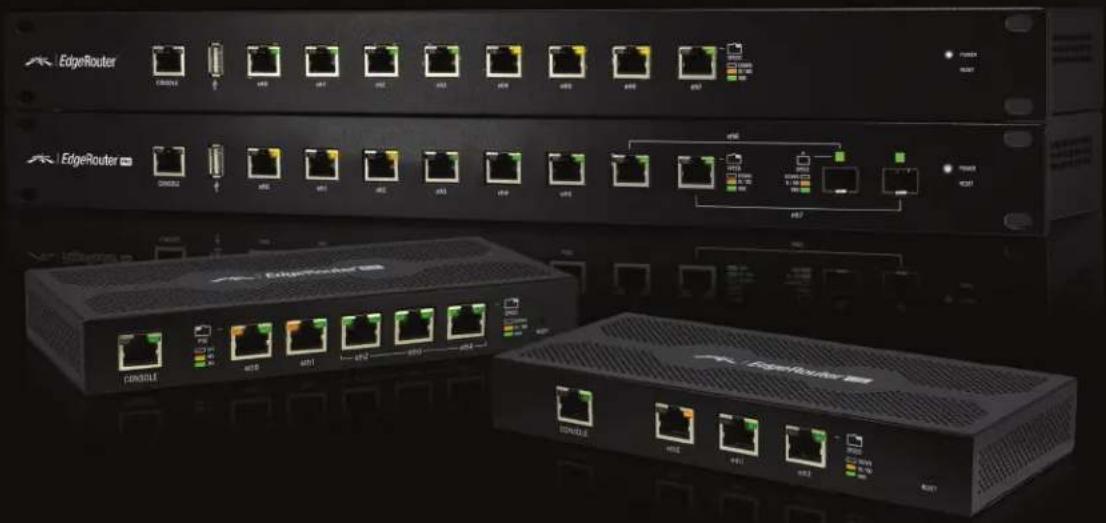
natural_image
Exterior view of two network switch units (EdgeRouter and Console) with multiple Ethernet ports and indicator lights, no visible text or symbols on the devices themselves.Table of Contents
Chapter 1: Overview....1
Introduction....1
Configuration Interface System Requirements....1
Hardware Overview and Installation ....1
Typical Deployment Scenarios....1
Chapter 2: Using EdgeOS....3
Ports and Status Information....3
Navigation ....3
Common Interface Options....4
Chapter 3: Dashboard Tab ....8
Services....8
Interfaces 9
Chapter 4: Routing Tab ....14
IPv6 Routing 14
Routes 15
OSPF....17
Chapter 5: Security Tab....20
Firewall Policies 20
NAT....24
Firewall/NAT Groups....28
VPN....29
Chapter 6: Services Tab 30
DHCP Server ....30
DNS....34
PPPoE....34
Chapter 7: Users Tab ....35
Local....35
Remote 36
Chapter 8: Wizards Tab ....37
Setup Wizards....37
Feature Wizards ....40
Chapter 9: Toolbox ....42
Ping....42
Trace....43
Discover....43
Packet Capture....43
Log Monitor....44
Appendix A: Command Line Interface 45
Overview....45
Access the CLI 45
CLI Modes....47
Appendix B: Contact Information....54
Ubiquiti Networks Support ....54
Chapter 1: Overview
Introduction
EdgeOS™ is a powerful, sophisticated operating system from Ubiquiti Networks™. It allows you to manage your EdgeRouter and networks. This User Guide is designed for use with version 1.3 or above of the EdgeOS Configuration Interface and all of the EdgeRouter models, which this User Guide will collectively refer to as EdgeRouter. Additional information is available on our website at:
http://community.ubnt.com/edgemax
http://documentation.ubnt.com/edgemax
| Product Name Model Number of Ports PoE | |||
| EdgeRouter Lite ERLite-3 3 | |||
| EdgeRouter PoE ERPoe-5 5 | √ | ||
| 8-Port EdgeRouter ER-8 8 | |||
| EdgeRouter PRO | ERPro-8 | 8* | |
* Two ports are either RJ45 or SFP.
Configuration
The intuitive EdgeOS Configuration Interface allows you to conveniently manage your EdgeRouter using your web browser. (See "Using EdgeOS" on page 3 for more information.) If you need to configure advanced features or prefer configuration by command line, you can use the Command Line Interface (CLI). (See "Command Line Interface" on page 45 for more information.)
Configuration Interface System Requirements
• Microsoft Windows 7, Windows 8, Linux, or Mac OS X
- Web Browser: Google Chrome, Mozilla Firefox, or Microsoft Internet Explorer 8 (or above)
Hardware Overview and Installation
The Quick Start Guide that accompanied your EdgeRouter includes a hardware description and instructions for hardware installation.
Typical Deployment Scenarios
While there are numerous scenarios that are possible, this section highlights three typical deployments:
- Small Office/Home Office (SOHO) Deployment
• Service Provider Deployment
• Corporate Deployment
SOHO Deployment
Click the Wizards tab and follow the on-screen instructions. See "Wizards Tab" on page 37 for more information.
Service Provider Deployment
This scenario uses six EdgeRouter devices:
- OSPF Area 0 to OSPF Area 1
- OSPF Area 0 to OSPF Area 2
- OSPF Area 1
- OSPF Area 1 to Internet
- OSPF Area 2
- OSPF Area 2 to Internet

flowchart
graph TD
    subgraph Site_A
        A1["Site A"] <-->|OSPF Area 1| A2["Site A"]
    end
    subgraph Site_B
        B1["Site B"]
        B2["Site B"]
    end
    Site_A <-->|Site-to-Site Link\nOSPF Area 0| B1
    Site_B <-->|OSPF Area 2| B2
    style Site_A fill:#f9f,stroke:#333
    style Site_B fill:#bbf,stroke:#333
Here are the typical steps to follow:
-
Configure the appropriate settings on the System tab (see "System" on page 4 for more information):
-
Host Name
- Time Zone
• Gateway - Name Server
-
Domain Name
• NTP -
Configure the interfaces on the Dashboard tab; see "Interfaces" on page 9 for more information.
- Configure OSPF settings on the Routing > OSPF tab; see "OSPF" on page 17 for more information.
- Configure DHCP server(s) on the Services tab; see "DHCP Server" on page 30 for more information.
- Configure NAT rules on the Security > NAT tab; see "NAT" on page 24 for more information.
™ User Guide
Chapter 1: OverviewEdgeOS
- Configure firewall rules on the Security > Firewall Policies tab; see "Firewall Policies" on page 20 for more information.
- Configure additional settings as needed for your network.
Corporate Deployment
This scenario uses a single EdgeRouter device. The three independent interfaces connect to the following:
- Internet
• DMZ
• LAN

flowchart
graph TD
    A["Firewall Policies"] --> B["DMZ"]
    B --> C["Internet"]
    C --> D["Cloud Network"]
    B --> E["LAN"]
    E --> F["Computer"]
    E --> G["Server"]
    style A fill:#f9f,stroke:#333
    style B fill:#ccf,stroke:#333
    style C fill:#cff,stroke:#333
    style D fill:#ffc,stroke:#333
    style E fill:#cfc,stroke:#333
    style F fill:#fcc,stroke:#333
    style G fill:#fcc,stroke:#333
Here are the typical steps to follow:
-
Configure the appropriate settings on the System tab (see "System" on page 4 for more information):
-
Host Name
- Time Zone
• Gateway - Name Server
-
Domain Name
• NTP -
Configure the interfaces on the Dashboard tab; see "Interfaces" on page 9 for more information.
-
Configure DHCP server(s) on the Services tab; see "DHCP Server" on page 30 for more information.
- Configure NAT rules on the Security > NAT tab; see "NAT" on page 24 for more information.
- Configure firewall rules on the Security > Firewall Policies tab; see "Firewall Policies" on page 20 for more information.
- Configure additional settings as needed for your network.
Chapter 2: Using EdgeOS
EdgeOS is a powerful, sophisticated operating system that manages your EdgeRouter. It offers both a browser-based interface (EdgeOS Configuration Interface) for easy configuration and a Command Line Interface (CLI) for advanced configuration.
To access the EdgeOS Configuration Interface:
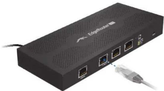
- Connect an Ethernet cable from the Ethernet port of your computer to the port labeled eth0 on the EdgeRouter.
natural_image
Exterior view of a black EdgeRisea network switch with Ethernet ports and USB cable (no text or symbols visible)- Configure the Ethernet adapter on your computer with a static IP address on the 192.168.1.x subnet (e.g., 192.168.1.100).

Note: As an alternative, you can connect a serial cable to the Console port of the EdgeRouter. See "Command Line Interface" on page 45 for more information.
- Launch your web browser. Type https://192.168.1.1 in the address field. Press enter (PC) or return (Mac).

- The login screen will appear. Enter ubnt in the Username and Password fields. Read the Ubiquiti License Agreement, and check the box next to I agree to the terms of this License Agreement to accept it. Click Login.

The EdgeOS Configuration Interface will appear, allowing you to customize your settings as needed.

Note: To enhance security, we recommend that you change the default login using one of the following:
- Set up a new user account on the Users > Local tab (preferred option). For details, go to "Add User" on page 35.
- Change the default password of the ubnt login on the Users > Local tab. For details, go to "Configure the User" on page 36.
Ports and Status Information
The Ports image displays active connections: purple indicates 10 Mbps, amber for 100 Mbps, and green for 1000 Mbps. The Status bar graphs display the following:
CPU The percentage of processing power used by the EdgeRouter.
RAM The percentage of RAM used by the EdgeRouter.
Uptime The duration of the EdgeRouter's activity.

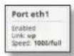
Place your mouse over a port to view the following:
Enabled/Disabled The administrative status is displayed.
Link The connection status is displayed.
Speed The speed (in Mbps) and duplex mode are displayed.
Navigation
The EdgeOS software consists of five primary tabs, and some of these tabs have sub-tabs. This User Guide covers each tab with a chapter. For details on a specific tab, refer to the appropriate chapter.
- Dashboard The "Dashboard Tab" on page 8 displays status information about services and interfaces. You can also configure interfaces and Virtual Local Area Networks (VLANs).
- Routing The "Routing Tab" on page 14 configures static routes and Open Shortest Path First (OSPF) settings, including metrics, areas, and interfaces.
- Security The "Security Tab" on page 20 configures firewall policies, Network Address Translation (NAT) rules, firewall/NAT groups, and PPTP VPN options.
- Services The "Services Tab" on page 30 configures DHCP servers, DNS forwarding, and the PPPoE server.
- Users The "Users Tab" on page 35 configures user accounts with administrator or operator access.
- Wizards The "Wizards Tab" on page 37 offers a variety of wizards: a setup wizard that configures the EdgeRouter for a typical SOHO deployment and feature wizards that configure port forwarding, TCP MSS clamping, and UPnP.
Depending on the tab you click, some of the screens display information and options in multiple sections. You can click the open/close tab to hide or display a section.

Common Interface Options
The common interface options are accessible from all tabs on the EdgeOS interface:
- Welcome
• CLI - Toolbox
- Alerts
- System
Required fields are marked by a blue asterisk *. When the information icon is displayed, you can click the icon for more information about an option.
Welcome
At the top left of the screen, click Welcome to view the Logout option:

Logout To manually log out of the EdgeRouter Configuration Interface, click this option.
CLI
Advanced users can make configuration changes using Linux commands. At the top right of the screen, click the CLI 52-74 ton. See "Command Line Interface" on page 45 for more information.
Toolbox
At the top right of the screen, click the Toolbox ➕ Toolbox ➕ button. The following network administration and monitoring tools are available:
• "Ping" on page 42
• "Trace" on page 43
• "Discover" on page 43
• "Packet Capture" on page 43
• "Log Monitor" on page 44
Alerts
The number of new alerts is displayed in a red popup.

At the bottom of the screen, click the Alerts tab.

A table displays the following information about each important event.

Message A description of the event is displayed.
Field The settings that are affected by the event are displayed.
Actions The following options are available:
- Remove Click this button to clear an alert.
- Clear All Click this button to clear all alerts.
Click the top right corner of the Alerts tab to close it.
System
At the bottom of the screen, click the System tab to access the device settings.

The device settings are organized into these sections:
• "Basic Settings" on page 5
• "Management Settings" on page 5
- "Configuration Management & Device Maintenance" on page 6
- "Restart & Shut Down Router" on page 7

Basic Settings
Host Name

System host name Enter a name for the EdgeRouter. The host name identifies the EdgeRouter as a specific device. For example, a .com URL typically uses this format:
Time Zone

Use Coordinated Universal Time (UTC) UTC is the international time standard used by Network Time Protocol (NTP) servers. If your routers are located in multiple time zones, then you may want to use UTC.
Time zone To set your network to a specific time zone, select Time zone and configure the following:
- Select continent/ocean Select your location.
- Select country/region Select your location.
- Select time zone Select your time zone.
Gateway

System gateway address Enter the IP address of your gateway. This will set up your default route. If you want to set up additional default routes, configure them as static routes on the Routing tab. See "Routing Tab" on page 14 for more information.
Name Server
Domain Name System (DNS) translates domain names to IP addresses; each DNS server on the Internet holds these mappings in its respective DNS database.

System name server Enter the IP address of your DNS server (example: 192.0.2.1 for IPv4 or 2001:db8::1 for IPv6). Click Add New to add additional servers.
Domain Name

System domain name Enter the domain name of your EdgeRouter. The domain name identifies the EdgeRouter's network on the Internet. For example, a .com URL typically uses this format:
host_name.
NTP
NTP is a protocol for synchronizing the clocks of computer systems over packet-switched, variable-latency data networks. You can use it to set the system time on the EdgeRouter. If the System Log option is enabled, then the system time is reported next to every log entry that registers a system event.

Automatically update system time using NTP By default, the EdgeRouter obtains the system time from a time server on the Internet.
Click Save to apply your changes.
Management Settings
SSH Server

Enable Enabled by default. This option allows SSH (Secure Shell) access to the EdgeRouter for remote configuration by command line. SSH uses encryption and authentication, so it is a secure form of communication. See "Command Line Interface" on page 45 for more information.
Port Specify the TCP/IP port of the SSH server. The default is 22.
Telnet Server

Enable Disabled by default. This option allows Telnet access to the EdgeRouter for remote configuration by command line. Telnet is not a secure form of communication, so we recommend SSH. See "Command Line Interface" on page 45 for more information.
Port Specify the TCP/IP port of the Telnet server. The default is 23.
System Log
Every logged message contains at least a system time and host name. Usually a specific service name that generates the system event is also specified within the message. Messages from different services have different contexts and different levels of detail. Usually error, warning, or informational system service messages are reported; however, more detailed debug level messages can also be reported. The more detailed the system messages reported, the greater the volume of log messages generated.

Log to remote server This option allows the EdgeRouter to send system log messages to a remote server. Enter the remote host IP address and TCP/IP port that should receive the system log (syslog) messages. 514 is the default port for the commonly used, system message logging utilities.

Note: Properly configure the remote host to receive syslog protocol messages.
SNMP Agent
Simple Network Monitor Protocol (SNMP) is an application layer protocol that facilitates the exchange of management information between network devices. Network administrators use SNMP to monitor network-attached devices for issues that warrant attention.
The EdgeRouter contains an SNMP agent, which does the following:
- Provides an interface for device monitoring using SNMP
• Communicates with SNMP management applications for network provisioning - Allows network administrators to monitor network performance and troubleshoot network problems
For the purpose of equipment identification, configure the SNMP agent with contact and location information:
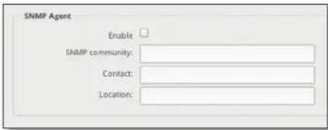
Enable Disabled by default. This option activates the SNMP agent.
SNMP community Specify the SNMP community string. It is required to authenticate access to MIB (Management Information Base) objects and functions as an embedded password. The device supports a read-only community string; authorized management stations have read access to all the objects in the MIB except the community strings, but do not have write access. The device supports SNMP v1. The default is public.
Contact Specify the contact who should be notified in case of emergency.
Location Specify the physical location of the EdgeRouter. Click Save to apply your changes.
Configuration Management & Device Maintenance
The controls in this section manage the device configuration routines, firmware maintenance, and reset to factory default settings.
Back Up Config
We recommend that you back up your current system configuration before updating the firmware or uploading a new configuration.

Download backup config file Click Download to download the current system configuration file.

Note: We strongly recommend that you save the configuration file in a secure location because it includes confidential information. The user login passwords are encrypted; however, other passwords and keys (such as those used for VPN, BGP, authentication, and RADIUS) are stored in plain text.
Restore Config

Upload config file Click Upload a file to locate the configuration file previously created by the Back Up Config option. Select the file and click Choose. We recommend that you back up your current system configuration before uploading the new configuration.

Note for advanced users: You can also upload a raw configuration file, /config/config.boot, using this option.
Upgrade System Image
Download the firmware file from downloads.ubnt.com and save it on your computer.
The firmware update is compatible with all configuration settings. The system configuration is preserved while the EdgeRouter is updated with a new firmware version. However, we recommend that you back up your current system configuration before updating the firmware.
Upload system image To update the EdgeRouter with new firmware, click Upload a file and locate the new firmware file. Then click Choose.
Please be patient, as the firmware update routine can take three to seven minutes. You cannot access the EdgeRouter until the firmware update routine is completed.

WARNING: Do not power off, do not reboot, and do not disconnect the EdgeRouter from the power supply during the firmware update process as these actions will damage the EdgeRouter!
Reset Config to Default
This option resets the EdgeRouter to the default configuration. This option will reboot the EdgeRouter, and the default configuration will be restored. We recommend that you back up your current system configuration before resetting the EdgeRouter to its default configuration.
Reset to Default To reset the EdgeRouter to its default configuration, click this option.
Restart & Shut Down Router Restart Router

Restart To turn the EdgeRouter off and back on again, click this option.
Shut Down Router
Shut Down To turn off the EdgeRouter, click this option.

WARNING: Click Shut Down to properly shut down the EdgeRouter. An improper shutdown, such as disconnecting the EdgeRouter from its power supply, runs the risk of data corruption!
Click the top right corner of the System tab to close it.

bar
| Service | Trx Rate (Kbps) | | :--- | :--- | | eth0 | 45 | | eth1 | 48 | | eth1,100 | 52 | | eth2 | 46 | | eth3 | 49 | | eth4 | 51 | | eth5 | 47 | | eth6 | 46 | | Total | 50 | | eth7 | 53 | | eth8 | 55 | | eth9 | 54 | | eth10 | 56 | | eth11 | 57 | | eth12 | 58 | | eth13 | 59 | | eth14 | 60 | | eth15 | 61 | | eth16 | 62 | | eth17 | 63 | | eth18 | 64 | | eth19 | 65 | | eth20 | 66 | | eth21 | 67 | | eth22 | 68 | | eth23 | 69 | | eth24 | 70 | | eth25 | 71 | | eth26 | 72 | | eth27 | 73 | | eth28 | 74 | | eth29 | 75 | | eth30 | 76 | | eth31 | 77 | | eth32 | 78 | | eth33 | 79 | | eth34 | 80 | | eth35 | 81 | | eth36 | 82 | | eth37 | 83 | | eth38 | 84 | | eth39 | 85 | | eth40 | 86 | | eth41 | 87 | | eth42 | 88 | | eth43 | 89 | | eth44 | 90 | | eth45 | 91 | | eth46 | 92 | | eth47 | 93 | | eth48 | 94 | | eth49 | 95 | | eth50 | 96 | | eth51 | 97 | | eth52 | 98 | | eth53 | 99 | | eth54 | 100 | | eth55 | 101 | | eth56 | 102 | | eth57 | 103 | | eth58 | 104 | | eth59 | 105 | | eth60 | 106 | | eth61 | 107 | | eth62 | 108 | | eth63 | 109 | | eth64 | 110 | | eth65 | 111 | | eth66 | 112 | | eth67 | 113 | | eth68 | 114 | | eth69 | 115 | | eth70 | 116 | | eth71 | 117 | | eth72 | 118 | | eth73 | 119 | | eth74 | 120 | | eth75 | 121 | | eth76 | 122 | | eth77 | 123 | | eth78 | 124 | | eth79 | 125 | | eth80 | 126 | | eth81 | 127 | | eth82 | 128 | | eth83 | 129 | | eth84 | 130 | | eth85 | 131 | | eth86 | 132 | | eth87 | 133 | | eth88 | 134 | | eth89 | 135 | | eth90 | 136 | | eth91 | 137 | | eth92 | 138 | | eth93 | 139 | | eth94 | 140 | | eth95 | 141 | | eth96 | 142 | | eth97 | 143 | | eth98 | 144 | | eth99 | 145 | | Ethiopia (trx Rate) = (Trx Rate / Trx Rate) / (Trx Rate / Trx Rate) / (Trx Rate / Trx Rate) / (Trx Rate / Trx Rate) / (Trx Rate / Trx Rate) / (Trx Rate / Trx Rate) / (Trx Rate / Trx Rate) / (Trx Rate / Trx Rate) / (Trx Rate / Trx Rate) / (Trx Rate / Trx Rate) / (Trx Rate / Trx Rate) * All Other net VLAN Search Description Interface Type IP Add: MTV Tx Rx Format Actions production net ethernet: 10.1.10.10/24: 1500: 43.91 Kbps: 2.87 Kbps Connected Actions lab networks ethernet: 1300: 984 bps: 1.90 Kbps: Connected Actions eth:1,100: ethanol: viam: 172.16.3.24/2/24: 1500: 968 bps: 1.14 Kbps: Connected Actions eth:2: ethanol: ethernet: 1500: 0 bps: 0 bps Disconnected Actions eth:3: ethanol: ethernet: 1500: 0 bps: 0 bps Disconnected Actions eth:4: ethanol: ethernet: 1500: 0 bps: 0 bps Disconnected Actions eth:5: ethanol: ethernet: 1500: 0 bps: 0 bps Disconnected Actions eth:6: ethanol: ethernet: 1.0.0.1/28: ethanol: 0 bps: Disconnected Actions eth:7: ethanol: ethernet: 1.0.0.1/3/28: ethanol: ethanol: Disconnected Actions Showing Y is # of X entries © Copyright ©2012-2013 Library Networks, Inc.Chapter 3: Dashboard Tab
The Dashboard tab displays status information about services and interfaces. You can also configure interfaces and Virtual Local Area Networks (VLANs). Any setting marked with a blue asterisk * is required.
Services
Status information is displayed. Each heading is a convenient link to the appropriate tab.

Routes
The following route types are listed:
- Connected
- Static
• RIP (Routing Information Protocol) - OSPF (Open Shortest Path First)
• EBGP (Exterior Border Gateway Protocol)
• IBGP (Interior Border Gateway Protocol)
The number of each route type and the total number of routes are displayed. Click Routes to display the Routing > Routes tab. Go to "Routes" on page 15 for more information.
OSPF
The OSPF status, settings, and number of areas are displayed. Click OSPF to display the Routing > OSPF tab. Go to "OSPF" on page 17 for more information.
NAT
The NAT (Network Address Translation) status and number of NAT rules are displayed. Click NAT to display the Security > NAT tab. Go to "NAT" on page 24 for more information.
Firewall
The firewall status and numbers of sets and rules are displayed. Click Firewall to display the Security > Firewall Policies tab. Go to "Firewall Policies" on page 20 for more information.
DHCP
The DHCP server status and numbers of active and inactive servers are displayed. Click DHCP to display the Services tab. Go to "DHCP Server" on page 30 for more information.
Interfaces
Distribution
Click Hide Distribution to hide the Interfaces > Distribution section. Click the remaining open/close tab to display the Interfaces > Distribution section again.

bar
| Month | A (FY10 Jan) | A (FY10 Feb) | A (FY10 Mar) | A (FY10 Apr) | A (FY10 May) | A (FY10 Jun) | A (FY10 Jul) | A (FY10 Aug) | A (FY10 Sep) | A (FY10 Oct) | A (FY10 Nov) | A (FY10 Dec) | |---|---|---|---|---|---|---|---|---|---|---|---|---| | Jan | 5.2 | 4.8 | 5.5 | 6.0 | 5.3 | 5.7 | 6.2 | 5.9 | 6.1 | 5.4 | 5.6 | 5.8 | | Feb | 5.3 | 4.9 | 5.6 | 6.1 | 5.4 | 5.8 | 6.3 | 6.0 | 6.2 | 5.5 | 5.7 | 6.0 | | Mar | 5.4 | 5.0 | 5.7 | 6.2 | 5.5 | 6.0 | 6.4 | 6.1 | 6.3 | 5.6 | 5.8 | 6.1 | | Apr | 5.5 | 5.1 | 5.8 | 6.3 | 5.6 | 6.1 | 6.5 | 6.2 | 6.4 | 5.7 | 5.9 | 6.2 | | May | 5.6 | 5.2 | 5.9 | 6.4 | 5.7 | 6.2 | 6.6 | 6.3 | 6.5 | 5.8 | 6.0 | 6.3 | | Jun | 5.7 | 5.3 | 6.0 | 6.5 | 5.8 | 6.3 | 6.7 | 6.4 | 6.6 | 5.9 | 6.1 | 6.4 | | Jul | 5.8 | 5.4 | 6.1 | 6.6 | 5.9 | 6.4 | 6.8 | 6.5 | 6.7 | 6.0 | 6.2 | 6.5 | | Aug | 5.9 | 5.5 | 6.2 | 6.7 | 6.0 | 6.5 | 7.0 | 6.7 | 6.9 | 6.1 | 6.3 | 6.6 | | Sep | 6.0 | 5.6 | 6.3 | 6.8 | 6.1 | 6.6 | 7.1 | 6.8 | 7.0 | 6.2 | 6.4 | 6.7 | | Oct | 6.1 | 5.7 | 6.4 | 6.9 | 6.2 | 6.7 | 7.2 | 6.9 | 7.1 | 6.3 | 6.5 | 6.8 | | Nov | 6.2 | 5.8 | 6.5 | 7.0 | 6.3 | 6.8 | 7.3 | 7.0 | 7.2 | 6.4 | 6.6 | 7.0 | | Dec | 6.3 | 5.9 | 6.6 | 7.1 | 6.4 | 6.9 | 7.4 | 7.1 | 7.3 | 6.5 | 6.7 | 7.1 | The chart displays two vertical bar charts comparing monthly values for each category from January to December, with the first chart showing a range of approximately 4 to8 and the second chart showing a range of approximately 4 to10, respectively, based on the visual comparison between the two series.
Select the physical or virtual interfaces you want to display from the Interfaces column.

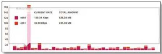
The TX Rate and RX Rate bar graphs display the current data traffic, which is color-coded to match the corresponding interface. The graph scale and throughput dimension (Mbps, for example) change dynamically depending on the mean throughput value. The statistics are updated automatically.

bar
| X-axis Label | Tx Rate (kbps) | |---|---| | 1 | 42 | | 2 | 43 | | 3 | 45 | | 4 | 46 | | 5 | 47 | | 6 | 48 | | 7 | 49 | | 8 | 50 | | 9 | 51 | | 10 | 52 | | 11 | 53 | | 12 | 54 | | 13 | 55 | | 14 | 56 | | 15 | 57 | | 16 | 58 | | 17 | 59 | | 18 | 60 | | 19 | 61 | | 20 | 62 | | 21 | 63 | | 22 | 64 | | 23 | 65 | | 24 | 66 | | 25 | 67 | | 26 | 68 | | 27 | 69 | | 28 | 70 | | 29 | 71 | | 30 | 72 | | 31 | 73 | | 32 | 74 | | 33 | 75 | | 34 | 76 | | 35 | 77 | | 36 | 78 | | 37 | 79 | | 38 | 80 | | 39 | 81 | | 40 | 82 | | 41 | 83 | | 42 | 84 | | 43 | 85 | | 44 | 86 | | 45 | 87 | | 46 | 88 | | 47 | 89 | | 48 | 90 | | 49 | 91 | | 50 | 92 | | 51 | 93 | | 52 | 94 | | 53 | 95 | | 54 | 96 | | 55 | 97 | | 56 | 98 | | 57 | 99 | | 58 | 100 | | 59 | 101 | | 60 | 102 | | 61 | 103 | | 62 | 104 | | 63 | 105 | | 64 | 106 | | 65 | 107 | | 66 | 108 | | 67 | 109 | | 68 | 110 | | 69 | 111 | | 70 | 112 | | 71 | 113 | | 72 | 114 | | 73 | 115 | | 74 | 116 | | 75 | 117 | | 76 | 118 | | 77 | 119 | | 78 | 120 | | 79 | 121 | | 80 | 122 | | 81 | 123 | | 82 | 124 | | 83 | 125 | | 84 | 126 | | 85 | 127 | | 86 | 128 | | 87 | 129 | | 88 | 130 | | 89 | 131 | | 90 | 132 | | 91 | 133 | | 92 | 134 | | 93 | 135 | | 94 | 136 | | 95 | 137 | | 96 | 138 | | 97 | 139 | | 98 | 140 | | 99 | 141 | | Note: The actual values may vary due to the random nature of the data generation. The provided values are just an example from the code execution.
bar
| Week | Rx Rate (Hzps) | |------|----------------| | 1 | 8 | | 2 | 10 | | 3 | 9 | | 4 | 7 | | 5 | 6 | | 6 | 8 | | 7 | 12 | | 8 | 15 | | 9 | 10 | | 10 | 8 | | 11 | 7 | | 12 | 9 | | 13 | 10 | | 14 | 11 | | 15 | 13 | | 16 | 14 | | 17 | 12 | | 18 | 10 | | 19 | 8 | | 20 | 6 | | 21 | 5 | | 22 | 7 | | 23 | 9 | | 24 | 10 | | 25 | 11 | | 26 | 12 | | 27 | 13 | | 28 | 14 | | 29 | 15 | | 30 | 16 | | 31 | 17 | | 32 | 18 | | 33 | 19 | | 34 | 20 | | 35 | 21 | | 36 | 22 | | 37 | 23 | | 38 | 24 | | 39 | 25 | | 40 | 26 | | 41 | 27 | | 42 | 28 | | 43 | 29 | | 44 | 30 | | 45 | 31 | | 46 | 32 | | 47 | 33 | | 48 | 34 | | 49 | 35 | | 50 | 36 | | 51 | 37 | | 52 | 38 | | 53 | 39 | | 54 | 40 | | 55 | 41 | | 56 | 42 | | 57 | 43 | | 58 | 44 | | 59 | 45 | | 60 | 46 | | 61 | 47 | | 62 | 48 | | 63 | 49 | | 64 | 50 | | 65 | 51 | | 66 | 52 | | 67 | 53 | | 68 | 54 | | 69 | 55 | | 70 | 56 | | 71 | 57 | | 72 | 58 | | 73 | 59 | | 74 | 60 | | 75 | 61 | | 76 | 62 | | 77 | 63 | | 78 | 64 | | 79 | 65 | | 80 | 66 | | 81 | 67 | | 82 | 68 | | 83 | 69 | | 84 | 70 | | 85 | 71 | | 86 | 72 | | 87 | 73 | | 88 | 74 | | 89 | 75 | | 90 | 76 | | 91 | 77 | | 92 | 78 | | 93 | 79 | | 94 | 80 | | 95 | 81 | | 96 | 82 | | 97 | 83 | | 98 | 84 | | 99 | 85 | | 100+ | - |Place your mouse over a bar to view the Current Rate and Total Amount of traffic for the selected interfaces.
bar
| Category | Current Rate (Kbps) | Total Amount (MB) | |---|---|---| | eth0 | 129.34 | 538.08 | | eth1 | 32.50 | 235.30 |All/Ethernet/VLAN
Add VLAN To create a new VLAN, click Add VLAN.
The Create a New VLAN screen appears.

- VLAN ID The VLAN ID is a unique value assigned to each VLAN at a single device; every VLAN ID represents a different VLAN. The VLAN ID range is 2 to 4094.
- Interface Select the appropriate interface.
• Description Enter keywords to describe this VLAN. - MTU Enter the MTU (Maximum Transmission Unit) value, which is the maximum packet size (in bytes) that a network interface can transmit. The default is 1500.
-
Address Select one of the following:
-
No address settings The VLAN uses no address settings. (In most cases, an address is needed.)
- Use DHCP The VLAN acquires network settings from a DHCPv4 server.
- Use DHCP for IPv6 The VLAN acquires network settings from a DHCPv6 server.
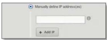
- Manually define IP address(es) Enter the static IP address (example: 192.0.2.1/24 for IPv4 or 2001:db8::1/32 for IPv6). Click Add IP to enter additional IP addresses.
Click Save to apply your changes, or click Cancel.
Search Allows you to search for specific text. Begin typing; there is no need to press enter. The results are filtered in real time as soon as you type two or more characters.
All/Ethernet/VLAN Click the appropriate tab to filter the interfaces as needed.
• All All interfaces are displayed by default.
- Ethernet All of the Ethernet interfaces are displayed.
• VLAN All VLANs are displayed.
A table displays the following information about each interface. Click a column heading to sort by that heading.

Description The keywords you entered to describe the interface are displayed.
Interface The name of the interface is displayed.

Note: A switch interface is created by default (EdgeRouter PoE only); however, there are no switched ports by default. To configure ports for the switch interface, click Actions > Config and go to "Configure the Switch" on page 12.
Type The type of interface is displayed.
PoE (Available for the EdgeRouter PoE only.) The status (off) or voltage (24v/48v) of the PoE feature is displayed.
IP Addr The IP address of the interface is displayed.
MTU The MTU (Maximum Transmission Unit) value of the interface is displayed. This is the maximum packet size (in bytes) that the interface can transmit.
TX The transmit speed of the interface is displayed.
RX The receive speed of the interface is displayed.
Status The connection status of the interface is displayed.
Actions Click the Actions button to access the following options:
- Config To configure the interface, click Config.
If the interface is a physical port, go to the Configure the Interface section.
If the interface is a VLAN, go to "Configure the VLAN" on page 11.
If the interface is a switch (available for the EdgeRouter PoE only), go to "Configure the Switch" on page 12.
- PoE (Available for the EdgeRouter PoE only.) To configure the PoE settings, click PoE. Go to "Configure the PoE Settings" on page 12.
- Disable Disable the interface while keeping its configuration. (The switch interface cannot be disabled.)

Note: If you disable a port, its PoE functionality remains. (This applies only to the EdgeRouter PoE.)
- Delete (Available for VLANs only.) Delete the VLAN from the EdgeRouter configuration.
Configure the Interface
After you click Config, the Interface Configuration screen appears.
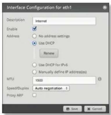
Make changes as needed.
• Description Enter keywords to describe this interface.
- Enable Check the box to enable the interface. All of the interfaces are saved in the system configuration file; however, only the enabled interfaces are active on the device.

Note: If you disable a port, its PoE functionality remains. (This applies only to the EdgeRouter PoE.)
- Address Select one of the following:
- No address settings The interface uses no address settings. (In most cases, an address is needed.)
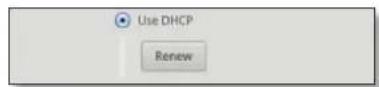
- Use DHCP The interface acquires network settings from a DHCPv4 server. Click the Renew button to acquire fresh network settings.
- No address settings The interface uses no address settings. (In most cases, an address is needed.) - Use DHCP The interface acquires network settings from a DHCPv4 server. Click the Renew button to acquire fresh network settings.
- Use DHCP for IPv6 The interface acquires network settings from a DHCPv6 server.
- Manually define IP address(es) Enter the static IP address (example: 192.0.2.1/24 for IPv4 or 2001:db8::1/32 for IPv6). Click Add IP to enter additional IP addresses.
- Use DHCP for IPv6 The interface acquires network settings from a DHCPv6 server. - Manually define IP address(es) Enter the static IP address (example: 192.0.2.1/24 for IPv4 or 2001:db8::1/32 for IPv6). Click Add IP to enter additional IP addresses.

- MTU Enter the MTU (Maximum Transmission Unit) value, which is the maximum packet size (in bytes) that a network interface can transmit. The default is 1500.
- Speed/Duplex The default is Auto negotiation. The EdgeRouter automatically negotiates transmission parameters, such as speed and duplex, with its counterpart. In this process, the networked devices first share their capabilities and then choose the fastest transmission mode they both support.
To manually specify the transmission link speed and duplex mode, select one of the following options: 100/full, 100/half, 10/full, or 10/half.
Full-duplex mode allows communication in both directions simultaneously. Half-duplex mode allows communication in both directions, but not simultaneously and only in one direction at a time.
- Proxy ARP Enable the EdgeRouter to answer a source host's ARP (Address Resolution Protocol) requests for the IP address of a destination host that is not located on the source host's network. ARP allows hosts on the same network to discover each other's IP address via a layer 2 broadcast to all MAC addresses. If they are not on the same network, the layer 2 broadcast will not reach its destination; however, the EdgeRouter can serve as the go-between if Proxy ARP is enabled.
Click Save to apply your changes, or click Cancel.
Configure the VLAN
After you click Config, the Interface Configuration screen appears.

Make changes as needed.
• VLAN ID The VLAN ID is displayed.
- Parent The interface belonging to this VLAN is displayed.
- Description Enter keywords to describe this interface.
- Enable Check the box to enable the VLAN. All of the VLANs are saved in the system configuration file; however, only the enabled VLANs are active on the device.
- Address Select one of the following:
- No address settings The interface uses no address settings. (In most cases, an address is needed.)
- Use DHCP The interface acquires network settings from a DHCPv4 server. Click the Renew button to acquire fresh network settings.

- Use DHCP for IPv6 The interface acquires network settings from a DHCPv6 server.
- Manually define IP address(es) Enter the static IP address (example: 192.0.2.1/24 for IPv4 or 2001:db8::1/32 for IPv6). Click Add IP to enter additional IP addresses.

- MTU Enter the MTU (Maximum Transmission Unit) value, which is the maximum packet size (in bytes) that a network interface can transmit. The default is 1500.
- Proxy ARP Enable the EdgeRouter to answer a source host's ARP (Address Resolution Protocol) requests for the IP address of a destination host that is not located on the source host's network. ARP allows hosts on the same network to discover each other's IP address via a layer 2 broadcast to all MAC addresses. If they are not on the same network, the layer 2 broadcast will not reach its destination; however, the EdgeRouter can serve as the go-between if Proxy ARP is enabled.
Click Save to apply your changes, or click Cancel.
Configure the Switch
(Available for the EdgeRouter PoE only.) After you click Config, the Interface Configuration screen appears.
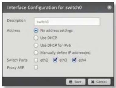
Make changes as needed.
• Description Enter keywords to describe this switch.
- Address Select one of the following:
- No address settings The switch uses no address settings. (In most cases, an address is needed.)
- Use DHCP The switch acquires network settings from a DHCPv4 server. Click the Renew button to acquire fresh network settings.
- Use DHCP for IPv6 The switch acquires network settings from a DHCPv6 server.
- Manually define IP address(es) Enter the static IP address (example: 192.0.2.1/24 for IPv4 or 2001:db8::1/32 for IPv6). Click Add IP to enter additional IP addresses.

- Switch Ports Select the ports for the switch interface.
- Proxy ARP Enable the EdgeRouter to answer a source host's ARP (Address Resolution Protocol) requests for the IP address of a destination host that is not located on the source host's network. ARP allows hosts on the same network to discover each other's IP address via a layer 2 broadcast to all MAC addresses. If they are not on the same network, the layer 2 broadcast will not reach its destination; however, the EdgeRouter can serve as the go-between if Proxy ARP is enabled.
Click Save to apply your changes, or click Cancel.
Configure the PoE Settings

Note: Before enabling PoE, check the specifications of your airMAX, airVision, mFi, UniFi, legacy, or third-party devices to ensure they support passive PoE and require the available amount of voltage.
(Available for the EdgeRouter PoE only.) After you click PoE, the PoE tab of the Interface Configuration screen appears.
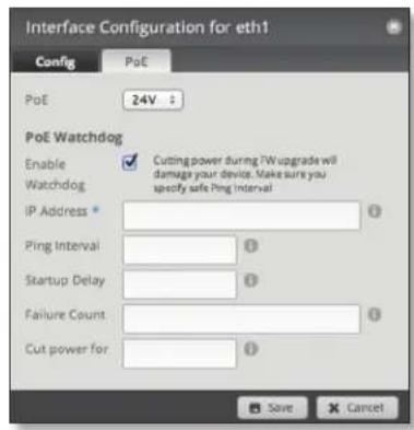
PoE is disabled by default on all ports. Make changes as needed.
• PoE Select one of the following:
- Off To disable PoE, select Off.

Note: To disable PoE, you must use this setting. If you disable a port, its PoE functionality remains.
- 24V To output 24V PoE to the connected device, select 24V.
- 48V To output 48V PoE to the connected device, select 48V.

Note: You must have a 48V power adapter (not included) powering the EdgeRouter PoE; otherwise, 48V PoE is not allowed.
PoE Watchdog
PoE Watchdog is only for PoE-enabled ports. It configures the device to continuously ping a user-defined IP address (it can be the Internet gateway, for example). If it is unable to ping under the user-defined constraints, then the device will automatically turn off PoE on the port, and then turn it back on. This option creates a kind of "fail-proof" mechanism.
PoE Watchdog is dedicated to continuous monitoring of the specific connection to the remote host using the Ping tool. The Ping tool works by sending ICMP echo request packets to the target host and listening for ICMP echo response replies. If the specified number of replies is not received, the tool reboots the device.
^TM User Guide
Chapter 3: Dashboard TabEdgeOS
- Enable Watchdog Enable the use of PoE Watchdog.
- IP Address To Ping Specify the IP address of the target host to be monitored by PoE Watchdog.
- Ping Interval Specify the time interval (in seconds) between the ICMP echo requests that are sent by PoE Watchdog. The default value is 300 seconds.
- Startup Delay Specify the initial time delay (in seconds) until the first ICMP echo requests are sent by PoE Watchdog. The default value is 300 seconds.
The Startup Delay value should be at least 60 seconds as the network interface and wireless connection initialization takes a considerable amount of time if the device is rebooted.
- Failure Count Specify the number of ICMP echo response replies. If the specified number of ICMP echo response packets is not received continuously, PoE Watchdog will reboot the device. The default value is 3.
- Cut power for Specify the number of seconds this port should pause PoE (if applicable).

WARNING: Cutting power during a firmware upgrade can damage your device. Ensure that you specify a safe Ping Interval.
Click Save to apply your changes, or click Cancel.

Chapter 4: Routing Tab
The Routing tab displays status information about a variety of connected, static, RIP, and OSPF routes. You can also configure static routes and OSPF options. Any setting marked with a blue asterisk * is required.
You have two sub-tabs:
Routes View route information and create static routes.
OSPF Configure OSPF options.
IPv6 Routing
IPv6 (Internet Protocol version 6) is gaining popularity and is bound to grow as IP addressing demands increase. The EdgeOS Configuration Interface supports IPv6 for the following options:
- System > Name Server configuration (Refer to "Name Server" on page 5.)
- Dashboard > VLAN configuration (Refer to "Add VLAN" on page 9.)
- Dashboard > Interface configuration (Refer to "Configure the Interface" on page 10.)
For IPv6 addresses, the EdgeOS Configuration Interface supports “::” (double-colon) notation, which substitutes “::” for a contiguous sequence of 16-bit blocks set to zero. Here is an example: 2001:db8::1
If written out, the IPv6 address becomes: 2001:db8:0000:0000:0000:0000:0000:0001
The EdgeOS Configuration Interface displays IPv6 addresses only in two locations:
• System > Name Server section
- Dashboard tab
The EdgeOS Configuration Interface will increase its support of IPv6 in future releases. For other options, you can use the CLI, which has comprehensive IPv6 support.

Note: Use the CLI to view IPv6 options configured in the CLI but not supported by the EdgeOS Configuration Interface.
Routes
A route determines how traffic travels to its destination network. If more than one route is suitable, the EdgeRouter uses administrative distance as a metric to compare all available routes, including directly connected routes, manually configured static routes, dynamic routes, and the default route. The EdgeRouter uses the route with the lowest administrative distance.
All/Static/Connected/RIP/OSPF
Add Static Route To create a new static route, click Add Static Route.
The Create Static Route screen appears.
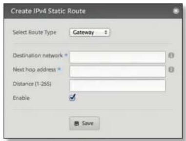
Complete the following:
- Select Route Type You have three options: Gateway, Interface, or Black Hole.
- Gateway Define a route using the IP address and subnet mask of the next hop gateway.

- Destination network Enter the IP address and subnet mask using slash notation:
The first default route is configured on the System tab; see "System gateway address" on page 5 for more information. To create multiple default routes, set up static routes and enter 0.0.0.0/0.
- Next hop address Enter the IP address.
- Distance (1-255) Enter the administrative distance. If there are identical routes from different sources (such as static, RIP, or OSPF), the EdgeRouter compares the routes and uses the route with the lowest distance.
- Enable Check the box to enable the route. Click Save to apply your changes.
- Interface Define a route using a next hop interface.
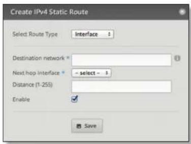
- Destination network Enter the IP address and subnet mask using slash notation:
- Next hop interface Select the appropriate interface from the drop-down list.
- Distance (1-255) Enter the administrative distance. If there are identical routes from different sources (such as static, RIP, and OSPF), the EdgeRouter compares the routes and uses the route with the lowest distance.
- Enable Check the box to enable the route.
Click Save to apply your changes.
- Black Hole Define a route that drops unwanted traffic.

- Destination network Enter the IP address and subnet mask using slash notation:
- Distance (1-255) Enter the administrative distance. If there are identical routes from different sources (such as static, RIP, and OSPF), the EdgeRouter compares the routes and uses the route with the lowest distance.
- Enable Check the box to enable the route.
Click Save to apply your changes.
Search Allows you to search for specific text. Begin typing; there is no need to press enter. The results are filtered in real time as soon as you type two or more characters.
All/Static/Connected/RIP/OSPF Click the appropriate tab to filter the routes as needed.
- All All routes are displayed by default.
- Static All static routes that you have configured are displayed.
- Connected All routes that are directly connected to the EdgeRouter are displayed.
- RIP All RIP (Routing Information Protocol) routes are displayed. RIP is an interior, distance vector routing protocol that uses hop count as a metric to determine the best route.
- OSPF All OSPF (Open Shortest Path First) routes are displayed. OSPF is an interior, link-state routing protocol that uses cost as a metric to determine the best route. The bandwidth of an interface determines the cost – the higher the bandwidth, the lower the cost.
A table displays the following information about each route. Click a column heading to sort by that heading.
| Region | Parameter | Year | Year | Year | Year | ||||
| 14 | 10-16.00 | dd | current | No | |||||
| 14 | 10-25.00 | dd/d | current | No | |||||
| 14 | 10-30.00 | nd/1 | current | No | |||||
| 14 | 10-35.00 | nd/2 | current | No |
Selected The status of the route, whether it has been selected for the routing table, is displayed.
Destination The destination IP address is displayed.
Next Hop The IP address of the next-hop interface is displayed.
Interface The name of the interface is displayed.
Route Type The type of route is displayed.
In FIB The forwarding status of the route, whether it is in the FIB (Forwarding Information Base), is displayed.
Actions Click the Actions button to access the following options:
- Config To configure the route, click Config. Go to the Configure the Static Route section below.
- Delete Delete the route; its configuration will be removed.
- Disable Disable the route while keeping its configuration. (This option is not available for black hole routes.)
Configure the Static Route
After you click Config, the Static Route Configuration screen appears.

Follow the instructions for your route type:
Gateway
- Route type The gateway route uses the IP address and subnet mask of the next hop gateway.
- Destination network The IP address and subnet mask are displayed in slash notation.
- Next hop address The IP address of the next hop gateway is displayed.
- Distance (1-255) Enter the administrative distance. If there are identical routes from different sources (such as static, RIP, and OSPF), the EdgeRouter compares the routes and uses the route with the lowest distance.
- Enable Check the box to enable the route.
Click Save to apply your changes.
Interface

- Route type The interface route uses the next hop interface.
- Destination network The IP address and subnet mask are displayed in slash notation.
- Next hop interface The name of the next hop interface is displayed.
- Distance (1-255) Enter the administrative distance. If there are identical routes from different sources (such as static, RIP, and OSPF), the EdgeRouter compares the routes and uses the route with the lowest distance.
- Enable Check the box to enable the route.
Click Save to apply your changes.
Black Hole
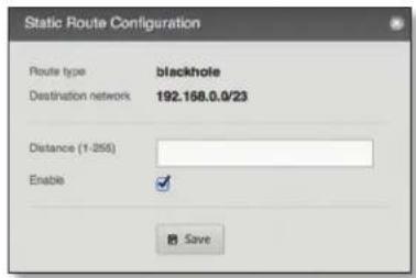
- Route type The black hole route drops unwanted traffic.
- Destination network The IP address and subnet mask are displayed in slash notation.
- Distance (1-255) Enter the administrative distance. If there are identical routes from different sources (such as static, RIP, and OSPF), the EdgeRouter compares the routes and uses the route with the lowest distance.
- Enable Check the box to enable the route.
Click Save to apply your changes.
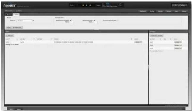
OSPF
Using Link State Advertisements, routers communicate with each other when there is a router or link status change. Each router maintains the information in a database, which is used to create and update a network map from the router's point of view. Each router then uses the map to build and update a routing table.
Router
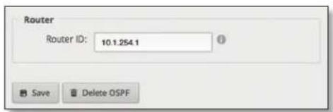
Router ID Enter the IP address that identifies a specific router in an OSPF network. In OSPF, the highest Router ID determines which router is the Designated Router (DR), which distributes updates to the other OSPF routers.
Click Save to apply your changes, or click Delete OSPF to remove the Router, Redistribution, and Area settings (Interfaces settings are retained).
Redistribution
A single router can use multiple routing protocols, such as OSPF and RIP, which use incompatible metrics. It must reconcile information from multiple protocols to determine which route to use for a specific destination network. You can change the metrics of the distributed protocol to create protocol compatibility.

Redistribute connected If enabled, the EdgeRouter connects an OSPF area to a network using a different routing protocol and redistributes the other protocol's directly connected routes into the OSPF area. These routes become external OSPF routes.
- Metric If there are multiple routes to the same destination, OSPF uses the metric to select a route for the routing table. Assign a cost value to the redistributed connected routes. The EdgeRouter can then use this metric to compare these routes to other OSPF routes.
Redistribute static If enabled, the EdgeRouter connects an OSPF area to a network using a different routing protocol and redistributes the other protocol's static routes into the OSPF area. These routes become external OSPF routes.
- Metric If there are multiple routes to the same destination, OSPF uses the metric to select a route for the routing table. Assign a cost value to the redistributed static routes. The EdgeRouter can then use this metric to compare these routes to other OSPF routes.
Announce default route If enabled, the EdgeRouter communicates the default route to the other routers of the OSPF network, eliminating the need to configure the default route on the other routers. The default route connects the OSPF network to an outside network.
Areas
To enhance scalability, an OSPF network is comprised of smaller sections called areas. At the minimum, there is the backbone area, called Area 0.

Add Area To create a new area, click Add Area.
The Create OSPF Area screen appears.

Complete the following:
- Area ID This is the number that identifies an area. It can be an integer or use a format similar to an IPv4 address.
-
Area Type This defines the routes that are acceptable inside the area. Select the appropriate option:
-
Normal/sec The default type accepts all routes.
- NSSA A NSSA (Not So Stubby Area) network is a variation of a stub network. It can import external routes from type 7 Link State Advertisements, which are NSSA-specific.
- Stub The network has no external routes. Typically, it has a default route for outbound traffic.
- Auth Type Authentication helps secure communication between routers. Select the appropriate option:
- Off No authentication is used.
- MD5/sec Each router uses a key (password) and key ID. This is the most secure option because the key is never transmitted.
- Plain text Each router uses a key. This provides minimal security because the key is transmitted in plain text format.
• Network Enter the IP address and subnet mask using slash notation:
Click Add New to enter more network addresses.
Click Save to apply your changes.
A table displays the following information about each OSPF Area. Click a column heading to sort by that heading.

Area ID The identification number of the area is displayed.
Area Type The type of area is displayed.
Auth Type The authentication type of the area is displayed.
Network The network address of the area is displayed.
Actions Click the Actions button to access the following options:
- Config To configure the OSPF Area, click Config. Go to the Configure the OSPF Area section.
- Delete Delete the OSPF Area.
Configure the OSPF Area
After you click Config, the OSPF Area Configuration screen appears.
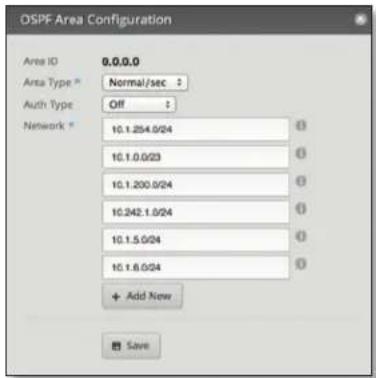
Make changes as needed.
- Area ID This is the number that identifies an area. It can be an integer or use a format similar to an IPv4 address.
-
Area Type This defines the routes that are acceptable inside the area. Select the appropriate option:
-
Normal/sec The default type accepts all routes.
- NSSA A NSSA (Not So Stubby Area) network is a variation of a stub network. It can import external routes from type 7 Link State Advertisements, which are NSSA-specific.
- Stub The network has no external routes. Typically, it has a default route for outbound traffic.
- Auth Type Authentication helps secure communication between routers. Select the appropriate option:
- Off No authentication is used.
- MD5/sec Each router uses a key (password) and key ID. This is the most secure option because the key is never transmitted.
- Plain text Each router uses a key. This provides minimal security because the key is transmitted in plain text format.
™ User Guide
Chapter 4: Routing Tab EdgeOS
• Network Enter the IP address and subnet mask using slash notation:
Click Add New to enter more network addresses.
Click Save to apply your changes.
Interfaces
You can configure interfaces with specific OSPF options.

Add OSPF Interface To create a new interface, click Add OSPF Interface.
The OSPF Interface Configuration screen appears.
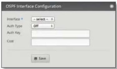
Complete the following:
- Interface Select the appropriate interface from the drop-down list.
-
Auth Type OSPF authentication helps secure communication between routers. Select the appropriate option:
-
Off No authentication is used.
- MD5/sec Each router uses a key (password) and key ID. This is the most secure option because the key is never transmitted.
- Plain text Each router uses a key. This provides minimal security because the key is transmitted in plain text format.
- Auth Key Enter the key used for authentication.
- Cost By default, the cost of an interface is based on its bandwidth; however, you can manually assign a cost to the interface.
Click Save to apply your changes.
A table displays the following information about each OSPF Interface. Click a column heading to sort by that heading.
Interface The name of the interface is displayed.
Cost The cost of the interface is displayed. OSPF uses cost as a metric to determine the best route.
Actions Click the Actions button to access the following options:
- Config To configure the OSPF Interface, click Config. Go to the Configure the OSPF Interface section.
- Delete Delete the OSPF Interface.
Configure the OSPF Interface
After you click Config, the OSPF Interface Configuration screen appears.

Make changes as needed.
- Interface The name of the interface is displayed. - Auth Type Authentication helps secure communication between routers. Select the appropriate option:
- Off No authentication is used.
- MD5/sec Each router uses a key (password) and key ID. This is the most secure option because the key is never transmitted.
-
Plain text Each router uses a key. This provides minimal security because the key is transmitted in plain text format.
-
Auth Key Enter the key used for authentication.
- Cost By default, the cost of an interface is based on its bandwidth; however, you can manually assign a cost to the interface.
Click Save to apply your changes.
Chapter 5: Security Tab
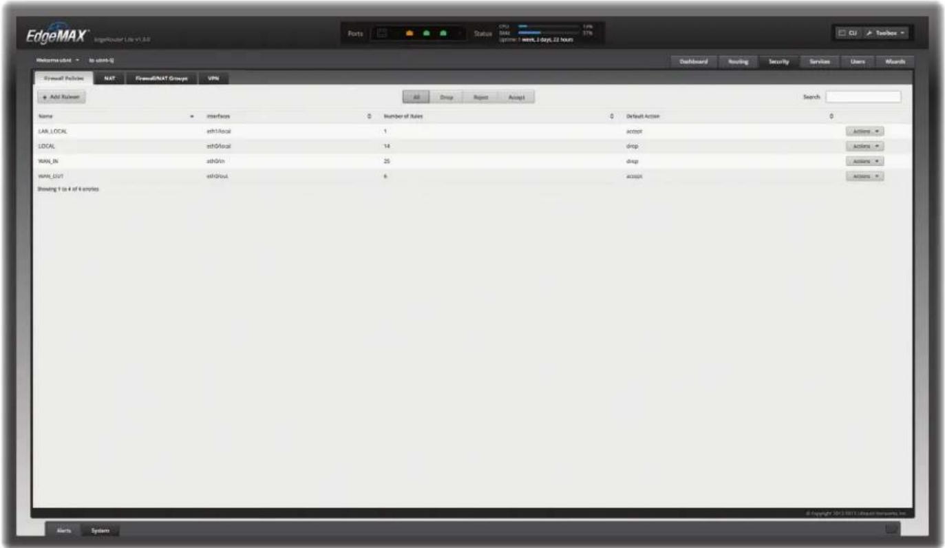
The Security tab displays status information about firewall policies, firewall groups, (Network Address Translation) rules, and PPTP VPN options. You can also configure these policies, groups, rules, and options. Any setting marked with a blue asterisk * is required.
You have four sub-tabs:
Firewall Policies Each firewall policy is a set of rules applied in the order you specify.
NAT View and create NAT rules.
Firewall/NAT Groups Create groups defined by IP address, network address, or port number.
VPN Configure the EdgeRouter as a PPTP VPN server.
Firewall Policies
A firewall policy is a set of rules with a default action. Firewall policies are applied before SNAT (Source Network Address Translation) and after DNAT (Destination Network Address Translation).
To create a firewall policy:
- Click the Firewall/NAT Groups tab, and create the applicable firewall groups. See "Firewall/NAT Groups" on page 28 for more information.
-
Click the Firewall Policies tab, and then click Add Policy. Configure the basic parameters. See the Add Policy description in the next column for more information.
-
Configure the details of the firewall policy. See "Configure the Firewall Policy" on page 21 for more information.
All/Drop/Reject/Accept
Add Policy To create a new policy, click Add Policy. The Create New Ruleset screen appears.

Complete the following:
• Name Enter a name for this policy.
• Description Enter keywords to describe this policy.
- Default action All policies have a default action if the packets do not match any rule. Select the appropriate default action:
- Drop Packets are blocked with no message.
- Reject Packets are blocked, and an ICMP (Internet Control Message Protocol) message is sent saying the destination is unreachable.
- Accept Packets are allowed through the firewall.
™ User Guide
Chapter 5: Security TabEdgeOS
- Default Log Check this box to log packets that trigger the default action.
Click Save to apply your changes.
Search Allows you to search for specific text. Begin typing; there is no need to press enter. The results are filtered in real time as soon as you type two or more characters.
All/Drop/Reject/Accept Click the appropriate tab to filter the policies by default action.
• All All policies are displayed by default.
- Drop All of the drop policies are displayed.
- Reject All of the reject policies are displayed.
- Accept All of the accept policies are displayed.
A table displays the following information about each policy. Click a column heading to sort by that heading.

Name The name of the policy is displayed.
Interfaces The specified interface and direction of traffic flow are displayed.
Number of Rules The number of rules in the policy is displayed.
Default Action The action that the policy will execute if the packets do not match any rule is displayed.
Actions Click the Actions button to access the following options:
- Edit Rules To configure the rules, click Edit Rules. Go to the Rules section in the next column.
- Configuration To configure the policy, click Configuration. Go to "Configuration" on page 24.
- Interfaces To select interfaces and direction of traffic flow for your policy, click Interfaces. Go to "Interfaces" on page 24.
- Stats To view statistics on firewall usage, click Stats. Go to "Stats" on page 24.
- Copy Policy To create a duplicate, click Copy Policy. The Copy Firewall Ruleset screen appears.

- Name Enter a new name for this policy.
Click Copy to confirm, or click Cancel.
- Delete Policy Remove the policy.
Configure the Firewall Policy
The Ruleset Configuration for _ screen appears.

You have four tabs available:
- Rules (see below)
- "Configuration" on page 24
- "Interfaces" on page 24
• "Stats" on page 24
Add New Rule To create a new rule, click Add New Rule. Go to "Add or Configure a Rule" on page 22.
Save Rule Order To change the rule order, click and drag a rule up or down the sequence, and then release the rule. When you are finished, click Save Rule Order.
Rules
A rule tells the EdgeRouter what action to take with a specific packet. Define the following:
• Criteria for matching packets
• Action to take with matching packets
Rules are organized into a set and applied in the specified Rule Order. If the packets match a rule's criteria, then its action is triggered. If not, then the next rule is applied.
A table displays the following information about each rule. Click a column heading to sort by that heading.
Order The rules are applied in the order specified. The number of the rule in this order is displayed.
Description The keywords you entered to describe this rule are displayed.
Source The source specified by this rule is displayed.
Destination The destination specified by this rule is displayed.
Protocol The protocol that matches the rule is displayed.
Action The action specified by this rule is displayed.
Actions Click the Actions button to access the following options:
- Basic To configure the basic options of a rule, click Basic. Go to "Basic" on page 22.
- Advanced To configure the advanced options of a rule, click Advanced. Go to "Advanced" on page 22.
- Source To configure the source options of a rule, click Source. Go to "Source" on page 23.
- Destination To configure the destination options of a rule, click Destination. Go to "Destination" on page 23.
- Time To configure the time options of a rule, click Time. Go to "Time" on page 23.
™ User Guide
Chapter 5: Security TabEdgeOS
- Copy Rule To create a duplicate, click Copy Rule. The duplicate rule appears at the bottom of the list.
- Delete Rule Remove the rule.
Add or Configure a Rule
The Rule Configuration for _ screen appears. You have five tabs available:
- Basic (see below)
• Advanced (see the next column) - "Source" on page 23
• "Destination" on page 23
• "Time" on page 23
Basic
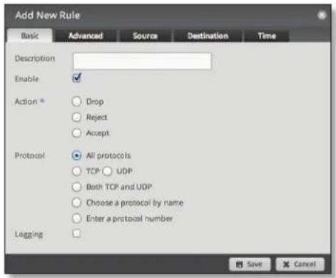
• Description Enter keywords to describe this rule.
- Enable Check the box to enable this rule.
- Action Select the action for packets that match this rule's criteria.
- Drop Packets are blocked with no message.
- Reject Packets are blocked, and an ICMP (Internet Control Message Protocol) message is sent saying the destination is unreachable.
- Accept Packets are allowed.
- Protocol
- All protocols Match packets of all protocols.
- TCP Match TCP packets.
- UDP Match UDP packets.
- Both TCP and UDP Match TCP and UDP packets.
- Choose a protocol by name Select the protocol from the drop-down list. Match packets of this protocol.
- Match all protocols except for this Match packets of all protocols except for the selected protocol.

- Enter a protocol number Enter the port number of the protocol. Match packets of this protocol.
- Match all protocols except for this Match packets of all protocols except for the selected protocol.

- Logging Check this box to log instances when the rule is matched.
Click Save to apply your changes, or click Cancel.
Advanced

• State This describes the connection state of a packet.
- Established Match packets that are part of a two-way connection.
- Invalid Match packets that cannot be identified.
- New Match packets creating a new connection.
-
Related Match packets related to established connections.
-
Recent Time Enter the number of seconds to monitor for attempts to connect from the same source.
- Recent Count Enter the number of times the same source is detected within the Recent Time duration. This helps thwart attacks using continual attempts to connect.
-
IPsec IPsec (Internet Protocol security) helps secure packet routing.
-
Don't match on IPsec packets Do not match any IPsec packets.
- Match inbound IPsec packets Match IPsec packets that are entering the EdgeRouter.
- Match inbound non-IPsec packets Match non-IPsec packets that are entering the EdgeRouter.
™ User Guide
Chapter 5: Security TabEdgeOS
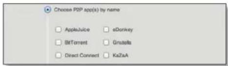
• P2P Match P2P (Peer-to-Peer) applications.
- None Do not match P2P connections.
- All Match all P2P connections.
- Choose P2P app(s) by name Match packets of the selected P2P application(s). Check the box of any P2P application on this list to select it.
Click Save to apply your changes, or click Cancel.
Source

- Address Enter the IP address of the source.
- Port Enter the port number or range of the source.
• MAC Address Enter the MAC address of the source.
Firewall groups are created on the Firewall/NAT Groups tab; see "Firewall/NAT Groups" on page 28 for more information. Select the appropriate group(s); you can specify up to two groups maximum in these combinations:
• An address group and port group
• A network group and port group
The packets must match both groups to apply the rule.
- Address Group or Interface Addr. Select the appropriate address group or interface address. If you select Other as the interface address, then enter the interface name in the field provided. The firewall rule will match the IP address of the selected interface.
• Network Group Select the appropriate network group. - Port Group Select the appropriate port group. Click Save to apply your changes, or click Cancel.
Destination

- Address Enter the IP address of the destination.
- Port Enter the port number of the destination.
Firewall groups are created on the Firewall/NAT Groups tab; see "Firewall/NAT Groups" on page 28 for more information. Select the appropriate group(s); you can specify up to two groups maximum in these combinations:
• An address group and port group
• A network group and port group
The packets must match both groups to apply the rule.
- Address Group or Interface Addr. Select the appropriate address group or interface address. If you select Other as the interface address, then enter the interface name in the field provided. The firewall rule will match the IP address of the selected interface.
• Network Group Select the appropriate network group. - Port Group Select the appropriate port group. Click Save to apply your changes, or click Cancel.
Time

- Month Days Enter the days of the month when the rule should be applied. Enter numbers in the range 1 to 31. If you enter more than one day, use commas to separate the numbers (example: 3, 4, 5).
- Match all month days except for these Match all days of the month except for the selected days.
™ User Guide
Chapter 5: Security TabEdgeOS
- Week Days Enter the days of the week when the rule should be applied. Enter Sun, Mon, Tue, Wed, Thu, Fri, or Sat. If you enter more than one day, use commas to separate the days (example: Mon, Tue, Wed).
- Match all week days except for these Match all days of the week except for the selected days.
- Start Date Enter the date the rule should start being applied. Use the YYYY-MM-DD (year-month-day) format.
- Start Time Enter the time the rule should start being applied. Use the 24-hour format, HH:MM:SS (hours:minutes:seconds).
- Stop Date Enter the date the rule should stop being applied. Use the YYYY-MM-DD (year-month-day) format.
- Stop Time Enter the time the rule should stop being applied. Use the 24-hour format, HH:MM:SS (hours:minutes:seconds).
- Interpret dates and times as UTC Check the box if your network uses UTC.
Click Save to apply your changes, or click Cancel.
Configuration

Name The name of this policy is displayed.
Description Enter keywords to describe this policy.
Default action All policies have a default action if the packets do not match any rule. Select the appropriate default action:
- Drop Packets are blocked with no message.
- Reject Packets are blocked, and an ICMP (Internet Control Message Protocol) message is sent saying the destination is unreachable.
- Accept Packets are allowed.
Default Log Check this box to log packets that trigger the default action.
Click Save Ruleset to apply your changes.
Interfaces

- Interface Select the appropriate interface from the drop-down list.
• Direction Select the direction of the traffic flow.
- in Match inbound packets.
- out Match outbound packets.
- local Match local packets.
- Add Interface Click Add Interface to enter more interfaces.
Click Save Ruleset to apply your changes.
Stats

A table displays the following statistics about each rule. Click a column heading to sort by that heading.
Rule The rules are applied in the order specified. The number of the rule in this order is displayed.
Packets The number of packets that triggered this rule is displayed.
Bytes The number of bytes that triggered this rule is displayed.
Action The action specified by this rule is displayed.
Description The keywords you entered to describe this rule are displayed.
NAT
NAT changes the addressing of packets. A NAT rule tells the EdgeRouter what action to take with a specific packet. Define the following:
• Criteria for matching packets
• Action to take with matching packets
Rules are organized into a set and applied in the specified Rule Order. If the packets match a rule's criteria, then its action is performed. If not, then the next rule is applied.

Source NAT Rules
Source NAT Rules change the source address of packets; a typical scenario is that a private source needs to communicate with a public destination. A Source NAT Rule goes from the private network to the public network and is applied after routing, just before packets leave the EdgeRouter.
Add Source NAT Rule To create a new rule, click Add Source NAT Rule. Go to "Add or Configure a Source NAT Rule" on page 25.
Save Rule Order To change the rule order, click and drag a rule up or down the sequence, and then release the rule. When you are finished, click Save Rule Order.
Search Allows you to search for specific text. Begin typing; there is no need to press enter. The results are filtered in real time as soon as you type two or more characters.
A table displays the following information about each rule. Click a column heading to sort by that heading.

Order The rules are applied in the order specified. The number of the rule in this order is displayed.
Description The keywords you entered to describe this rule are displayed.
Source Addr. The source IP address is displayed.
Source Port The source port number is displayed.
Dest. Addr. The destination IP address is displayed.
Dest. Port The destination port number is displayed.
Translation A description of the translation (such as masquerade to eth_) is displayed.
Count The number of translations is displayed.
Actions Click the Actions button to access the following options:
- Config To configure the rule, click Config. Go to the Add or Configure a Source NAT Rule section below.
- Copy To create a duplicate, click Copy. The duplicate rule appears at the bottom of the list.
- Delete Remove the rule.
Add or Configure a Source NAT Rule
After you click Config, the Source NAT Rule Configuration screen appears.

• Description Enter keywords to describe this rule.
- Enable Check the box to enable this rule.
- Outbound Interface Select the interface through which the outgoing packets exit the EdgeRouter. This is required only for Source NAT Rules that use Masquerade.
• Translation Select one of the following:
- Use Masquerade Masquerade is a type of Source NAT. If enabled, the source IP address of the packets becomes the public IP address of the outbound interface.
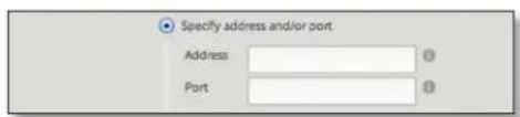
- Specify address and/or port If enabled, the source IP address of the packets becomes the specified IP address and port.
- Address Enter the IP address that will replace the source IP address of the outgoing packet. You can also enter a range of IP addresses; one of them will be used.
- Port Enter the port number that will replace the source port number of the outgoing packet. You can also enter a range of port numbers; one of them will be used.
- Exclude from NAT Check the box to exclude packets that match this rule from NAT.
™ User Guide
Chapter 5: Security TabEdgeOS
- Enable Logging Check this box to log instances when the rule is matched.
-
Protocol Select one of the following:
-
All protocols Match packets of all protocols.
- TCP Match TCP packets.
- UDP Match UDP packets.
- Both TCP and UDP Match TCP and UDP packets.
- Choose a protocol by name Select the protocol from the drop-down list. Match packets of this protocol.
- Match all protocols except for this Match packets of all protocols except for the selected protocol.

- Enter a protocol number Enter the port number of the protocol. Match packets of this protocol.
- Match all protocols except for this Match packets of all protocols except for the selected protocol.
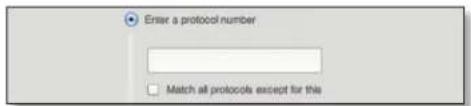
- Src Address Enter the IP address or network address of the source. You can also enter a range of IP addresses; one of them will be used.

Note: If you enter a network address, enter the IP address and subnet mask using slash notation:
- Src Port Enter the port name or number of the source. You can also enter a range of port numbers; one of them will be used.
NAT groups are created on the Firewall/NAT Groups tab; see "Firewall/NAT Groups" on page 28 for more information. Select the appropriate group(s); you can specify up to two groups maximum in these combinations:
• An address group and port group
• A network group and port group
The packets must match both groups to apply the rule.
- Src Address Group or Interface Addr. Select the appropriate address group or interface address. If you select Other as the interface address, then enter the interface name in the field provided. The NAT rule will match the IP address of the selected interface.
- Src Network Group Select the appropriate network group.
- Src Port Group Select the appropriate port group.
- Dest. Address Enter the IP address or network address of the destination. You can also enter a range of IP addresses; one of them will be used.

Note: If you enter a network address, enter the IP address and subnet mask using slash notation:
- Dest. Port Enter the port name or number of the destination. You can also enter a range of port numbers; one of them will be used.
- Dest Address Group or Interface Addr. Select the appropriate address group or interface address. If you select Other as the interface address, then enter the interface name in the field provided. The NAT rule will match the IP address of the selected interface.
- Dest Network Group Select the appropriate network group.
- Dest Port Group Select the appropriate port group. Click Save to apply your changes, or click Cancel.
Destination NAT Rules
Destination NAT Rules change the destination address of packets; a typical scenario is that a public source needs to communicate with a private destination. A Destination NAT Rule goes from the public network to the private network and is applied before routing.

Add Destination NAT Rule To create a new rule, click Add Destination NAT Rule. Go to the Add or Configure a Destination NAT Rule section.
Save Rule Order To change the rule order, click and drag a rule up or down the sequence, and then release the rule. When you are finished, click Save Rule Order.
Search Allows you to search for specific text. Begin typing; there is no need to press enter. The results are filtered in real time as soon as you type two or more characters.
A table displays the following information about each rule. Click a column heading to sort by that heading.

Order The rules are applied in the order specified. The number of the rule in this order is displayed.
Description The keywords you entered to describe this rule are displayed.
Source Addr. The source IP address is displayed.
Source Port The source port number is displayed.
Dest. Addr. The destination IP address is displayed.
Dest. Port The destination port number is displayed.
Translation A description of the translation (such as to
Count The number of translations is displayed.
Actions Click the Actions button to access the following options:
- Config To configure the rule, click Config. Go to the Add or Configure a Destination NAT Rule section below.
- Copy To create a duplicate, click Copy. The duplicate rule appears at the bottom of the list.
- Delete Remove the rule.
Add or Configure a Destination NAT Rule
After you click Config, the Destination NAT Rule Configuration screen appears.
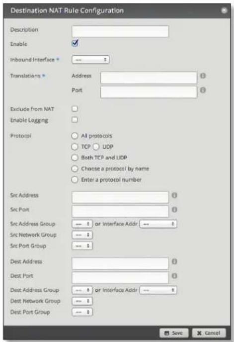
• Description Enter keywords to describe this rule.
- Enable Check the box to enable this rule.
-
Inbound Interface Select the interface through which the incoming packets enter the EdgeRouter.
• Translations Complete the following: -
Address Enter the IP address that will replace the destination IP address of the incoming packet.
-
Port Enter the port number that will replace the destination port number of the incoming packet.
-
Exclude from NAT Check the box to exclude packets that match this rule from NAT.
- Enable Logging Check this box to log instances when the rule is matched.
-
Protocol
-
All protocols Match packets of all protocols.
- TCP Match TCP packets.
- UDP Match UDP packets.
- Both TCP and UDP Match TCP and UDP packets.
- Choose a protocol by name Select the protocol from the drop-down list. Match packets of this protocol.
- Match all protocols except for this Match packets of all protocols except for the selected protocol.

- Enter a protocol number Enter the port number of the protocol. Match packets of this protocol.
- Match all protocols except for this Match packets of all protocols except for the selected protocol.

- Src Address Enter the IP address or network address of the source. You can also enter a range of IP addresses; one of them will be used.

Note: If you enter a network address, enter the IP address and subnet mask using slash notation:
- Src Port Enter the port name or number of the source. You can also enter a range of port numbers; one of them will be used.
NAT groups are created on the Firewall/NAT Groups tab; see "Firewall/NAT Groups" on page 28 for more information. Select the appropriate group(s); you can specify up to two groups maximum in these combinations:
• An address group and port group
• A network group and port group
The packets must match both groups to apply the rule.
- Src Address Group or Interface Addr. Select the appropriate address group or interface address. If you select Other as the interface address, then enter the interface name in the field provided. The NAT rule will match the IP address of the selected interface.
- Src Network Group Select the appropriate network group.
- Src Port Group Select the appropriate port group.
- Dest. Address Enter the IP address or network address of the destination. You can also enter a range of IP addresses; one of them will be used.

Note: If you enter a network address, enter the IP address and subnet mask using slash notation:
- Dest. Port Enter the port name or number of the destination. You can also enter a range of port numbers; one of them will be used.
- Dest Address Group or Interface Addr. Select the appropriate address group or interface address. If you select Other as the interface address, then enter the interface name in the field provided. The NAT rule will match the IP address of the selected interface.
- Dest Network Group Select the appropriate network group.
- Dest Port Group Select the appropriate port group. Click Save to apply your changes, or click Cancel.
Firewall/NAT Groups
Create groups organized by IP address, network address, or port number.

All/Address/Network/Port
Add Group To create a new group, click Add Group.
The Create New Group screen appears.

Complete the following:
• Name Enter a name for this group.
• Description Enter keywords to describe this group.
- Group Type Select the appropriate option:
- Address Group Define a group by IP address.
- Network Group Define a group by network address.
- Port Group Define a group by port numbers.
Click Save to apply your changes.
Search Allows you to search for specific text. Begin typing; there is no need to press enter. The results are filtered in real time as soon as you type two or more characters.
All/Address/Network/Port Click the appropriate tab to filter the groups as needed.
• All All groups are displayed by default.
- Address All of the address groups are displayed.
• Network All of the network groups are displayed.
• Port All of the port groups are displayed.
A table displays the following information about each group. Click a column heading to sort by that heading.
| Gene | Description | S. total | S. number of genes identified | P |
| unknowngroup | 1 | 20000472 | ||
| A | unknowngroup | 11 | 20000533 | |
| B | unknowngroup | 13 | 20000533 | |
| C | Genetic variant | unknowngroup | 1 | 20000533 |
| D | unknowngroup | 1 | 20000533 | |
| E | Genesome | unknowngroup | 7 | 20000533 |
| F | unknowngroup | 7 | 20000533 | |
| G | unknowngroup | 1 | 20000533 | |
| HbA1c | Unknown | unknowngroup | 1 | 20000533 |
| HbA1c-1a | Unknown | unknowngroup | 8 | 20000533 |
| HbA1c-2 | Unknown | unknowngroup | 1 | 20000533 |
| HbA1c-3a | Unknown | unknowngroup | 1 | 20000533 |
| HbA1c-4a | Unknown | unknowngroup | 1 | 20000533 |
| HbA1c-5a | Unknown | unknowngroup | 1 | 20000533 |
| HbA1c-6a | Unknown | unknowngroup | 1 | 20000533 |
| HbA1c-7a | Unknown | unknowngroup | 1 | 20000533 |
Name The name of the group is displayed.
Description The keywords you entered to describe the group are displayed.
Type The type of group is displayed.
Number of group members The number of members is displayed.
Actions Click the Actions button to access the following options:
- Config To configure the group, click Config. Go to the Configure the Firewall/NAT Group section below.
- Delete Remove the group.
Configure the Firewall/NAT Group
After you click Config, the Edit Firewall Group screen appears. Follow the instructions for your group type:
- Address Group Make changes as needed.
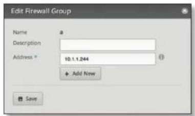
- Name The name of this group is displayed.
- Description Enter keywords to describe this group.
- Address Enter the IP address or range of addresses (examples: 192.0.2.1 or 192.0.2.1-15). Click Add New to enter more IP addresses.
Click Save to apply your changes.
• Network Group Make changes as needed.

- Name The name of this group is displayed.
- Description Enter keywords to describe this group.
- Network Enter the IP address and subnet mask using slash notation:
Click Add New to enter more network addresses.
Click Save to apply your changes.
• Port Group Make changes as needed.

- Name The name of this group is displayed.
- Description Enter keywords to describe this group.
- Port Enter the port name, number, or range. Click Add New to enter more ports.
Click Save to apply your changes.
VPN
A common type of VPN uses PPTP (Point-to-Point Tunneling Protocol). The EdgeRouter can function as a PPTP VPN server so a remote VPN client can access the LAN using a PPTP VPN tunnel over the Internet.
PPTP Server
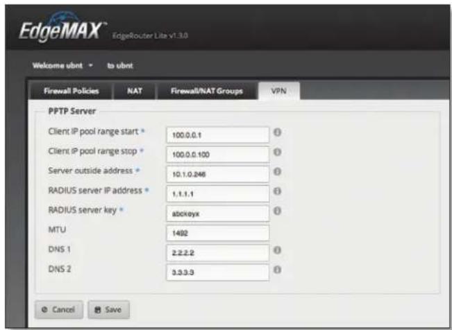
Client IP pool range start The client IP pool is the pool of IP addresses that remote VPN clients will use. Enter the starting IP address of the range (this address must in a /24 subnet).
Client IP pool range stop Enter the last IP address of the range.
Server outside address Enter the IP address that VPN clients will connect to; this is the outside or external address of the PPTP server.
RADIUS server IP address The RADIUS (Remote Access Dial-In User Service) server provides authentication to help secure VPN tunnels. Enter the IP address of the RADIUS server.
RADIUS server key Enter the key shared with the RADIUS server.
MTU Enter the MTU (Maximum Transmission Unit) value, which is the maximum packet size (in bytes) that a network interface can transmit. The default is 1492 for the PTTP VPN connection.
DNS 1 Enter the IP address of the primary remote access DNS server that your VPN client will use.
DNS 2 Enter the IP address of the secondary remote access DNS server.
Click Save to apply your changes, or click Cancel.

Chapter 6: Services Tab
The Services tab displays status information about DHCP servers, DNS forwarding, and the PPPoE server. Any setting marked with a blue asterisk * is required.
You have three sub-tabs:
DHCP Server Configure DHCP servers to implement different subnets on the independent interfaces.
DNS Configure DNS forwarding so the EdgeRouter receives all LAN DNS requests and forwards them to the service provider's DNS server.
PPPoE Server Configure the PPPoE server so a remote PPPoE client can establish a tunnel to the EdgeRouter for network access.
DHCP Server
A DHCP server assigns IP addresses to DHCP clients. You can configure multiple DHCP servers to assign IP ranges in different subnets on the different interfaces.
Add DHCP Server To create a new DHCP server, click Add DHCP Server.
The Create DHCP Server screen appears.
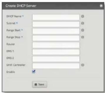
Complete the following:
• DHCP Name Enter a name for this DHCP server.
- Subnet Enter the IP address and subnet mask using slash notation:
- Range Start Enter the starting IP address of the range.
- Range Stop Enter the last IP address of the range.
- Router Enter the default route of the DHCP clients. The DHCP clients route all packets to this IP address, which is the EdgeRouter's own IP address in most cases.
- DNS 1 Enter the IP address of the primary DNS server. Your ISP may provide this information, or you can use Google's DNS server at 8.8.8.8.
• DNS 2 Enter the IP address of the secondary DNS server.
™ User Guide
Chapter 6: Services Tab EdgeOS
- UniFi Controller Enter the IP address of the UniFi® Controller. The DHCP server will return the UniFi Controller's IP address to its DHCP clients, so if a client is a UniFi AP, it will know how to contact the UniFi Controller.
- Enable Check the box to enable this DHCP server. Click Save to apply your changes, or click Cancel.
Search Allows you to search for specific text. Begin typing; there is no need to press enter. The results are filtered in real time as soon as you type two or more characters.
A table displays the following information about each DHCP server. Click a column heading to sort by that heading.

Name The name of the DHCP server is displayed.
Subnet The IP address and subnet mask of the DHCP server are displayed.
Pool size The total number of IP addresses is displayed.
Leased The number of leased IP addresses is displayed.
Available The number of available IP addresses is displayed.
Actions Click the Actions button to access the following options:
- View Leases To view the current DHCP leases, click View Leases. Go to the Configure the DHCP Server > Leases section.
- Configure Static Map To map static IP addresses to MAC addresses, click Configure Static Map. Go to "Static MAC/IP Mapping" on page 32.
- View Details To configure the DHCP server, click View Details. Go to "Details" on page 33.
- Delete Delete the DHCP server; its configuration will be removed.
- Disable Disable the DHCP server while keeping its configuration.
Configure the DHCP Server
The DHCP Server - screen appears. You have three tabs available.
Leases
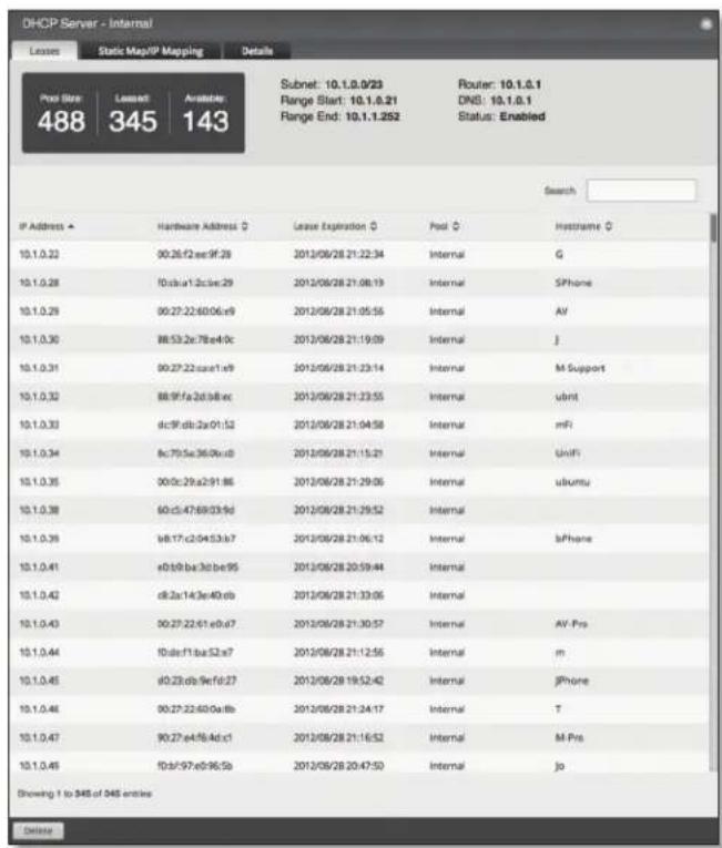
The top section displays the following status information:
- Pool Size The total number of IP addresses is displayed. The DHCP server assigns IP address from the pool (or group) of IP addresses.
- Leased The number of used IP addresses is displayed.
• Available The number of available IP addresses is displayed. - Subnet The IP address and subnet mask of the DHCP server are displayed in slash notation.
- Range Start The starting IP address of the range is displayed.
- Range End The last IP address of the range is displayed.
- Router The default route of the DHCP clients is displayed. The DHCP clients route all packets to this IP address, which is the EdgeRouter's own IP address in most cases.
• DNS The IP address of the DNS server is displayed. - Status The Enabled/Disabled status of the DHCP server is displayed.
- Search Allows you to search for specific text. Begin typing; there is no need to press enter. The results are filtered in real time as soon as you type two or more characters.
A table displays the following information about each DHCP client. Click a column heading to sort by that heading.
| IP Address - | Hardware Address ◊ | Lease Expiration ◊ | Pool ◊ | Histogramx ◊ |
| 10.1.0.22 | 90:26/22:ee:9f:28 | 2013/08/28 21:22:34 | Internal | G |
| 10.1.0.28 | 10:ct:a1.2:c:be:29 | 2013/08/28 21:08:19 | Internal | SPhone |
| 10.1.0.29 | 00:27:22:60:06:e9 | 2013/08/28 21:05:56 | Internal | AV |
| 10.1.0.30 | 88:53:2c:78:e4:5c | 2013/08/28 21:19:09 | Internal | J |
- IP Address The IP address assigned to the DHCP client is displayed.
- Hardware Address The MAC address of the DHCP client is displayed.
- Lease Expiration The date and time when the DHCP lease will expire is displayed.
- Pool The name of the DHCP server is displayed.
- Hostname The name used to identify the DHCP client is displayed.
At the bottom of the screen, you can click Delete to delete the DHCP server and its configuration.
Static MAC/IP Mapping

The top section displays the following status information:
- Pool Size The total number of IP addresses is displayed.
- Leased The number of used IP addresses is displayed.
• Available The number of available IP addresses is displayed. -
Subnet The IP address and subnet mask of the DHCP server are displayed in slash notation.
-
Range Start The starting IP address of the range is displayed.
- Range End The last IP address of the range is displayed.
- Router The default route of the DHCP clients is displayed. The DHCP clients route all packets to this IP address, which is the EdgeRouter's own IP address in most cases.
• DNS The IP address of the DNS server is displayed. - Status The Enabled/Disabled status of the DHCP server is displayed.
- Create New Mapping To map a static IP address to a specific MAC address, click Create New Mapping. The Create Static MAC/IP Mapping appears.
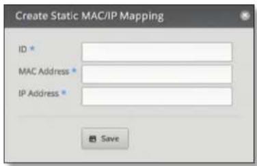
Complete the following:
- ID Enter a name for this mapping.
- MAC Address Enter the MAC address of the DHCP client.
- IP Address Enter the IP address that should be assigned.
Click Save to apply your changes.
- Search Allows you to search for specific text. Begin typing; there is no need to press enter. The results are filtered in real time as soon as you type two or more characters.
A table displays the following information about each static MAC/IP mapping. Click a column heading to sort by that heading.
• Name The name of the mapping is displayed.
• MAC Address The MAC address of the DHCP client is displayed.
- IP Address The IP address assigned to the corresponding MAC address is displayed.
- Actions Click the Actions button to access the following options:
- Config To configure the mapping, click Config. Go to "Configure Static MAC/IP Mapping" on page 33.
- Delete Remove the selected mapping.
At the bottom of the screen, you can click Delete to delete the DHCP server and its configuration.
Configure Static MAC/IP Mapping
The Static MAC/IP Mapping screen appears.

Make changes as needed.
- ID The name of this mapping is displayed.
- MAC Address Enter the MAC address of the DHCP client.
- IP Address Enter the IP address that should be assigned.
Click Save to apply your changes.
Details
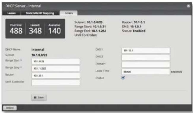
The top section displays the following status information:
- Pool Size The total number of IP addresses is displayed.
- Leased The number of used IP addresses is displayed.
• Available The number of available IP addresses is displayed. - Subnet The IP address and subnet mask of the DHCP server are displayed in slash notation.
- Range Start The starting IP address of the range is displayed.
- Range End The last IP address of the range is displayed.
- Router The default route of the DHCP clients is displayed. The DHCP clients route all packets to this IP address, which is the EdgeRouter's own IP address in most cases.
• DNS The IP address of the DNS server is displayed. - Status The Enabled/Disabled status of the DHCP server is displayed.
The rest of the Details tab displays the following:
• DHCP Name The name of the DHCP server is displayed.
- Subnet The IP address and subnet mask of the DHCP server are displayed in slash notation.
Make changes as needed to the following options:
- Range Start Enter the starting IP address of the range.
- Range Stop Enter the last IP address of the range.
- Router Enter the default route of the DHCP clients. The DHCP clients route all packets to this IP address, which is the EdgeRouter's own IP address in most cases.
- UniFi Controller Enter the IP address of the UniFi Controller. The DHCP server will return the UniFi Controller's IP address to its DHCP clients, so if a client is a UniFi AP, it will know how to contact the UniFi Controller.
- DNS 1 Enter the IP address of the primary DNS server. Your ISP may provide this information, or you can use Google's DNS server at 8.8.8.8.
• DNS 2 Enter the IP address of the secondary DNS server.
- Domain Enter the domain name for DHCP clients.
- Lease Time Enter the period of time (in seconds) that a DHCP lease should last.
- Enable Check the box to enable this DHCP server.
Click Save to apply your changes.
At the bottom of the screen, you can click Delete to delete the DHCP server and its configuration.
DNS
The EdgeRouter receives all LAN DNS requests and forwards them to the service provider's DNS server. The EdgeRouter receives responses from the DNS server and forwards them to the LAN clients.
DNS Forwarding

Cache Size Completed DNS requests are cached so response time is faster for cached entries, and there is less traffic traveling to the DNS server. Enter the maximum number of DNS queries to cache.
Interface Select the appropriate interface that the EdgeRouter will listen to so it can forward DNS requests.
Add Listen Interface You can select multiple interfaces. To add another interface for DNS forwarding, click Add Listen Interface. From the new Interface drop-down menu, select the appropriate interface.
Click Save to apply your changes, or click Cancel.
PPPoE
The EdgeRouter can function as a PPPoE (Point-to-Point Protocol over Ethernet) server so a remote PPPoE client can establish a tunnel to the EdgeRouter for network access.
PPPoE Server

Client IP pool range start The client IP pool is the pool of IP addresses that remote PPPoE clients will use. Enter the starting IP address of the range (this address must in a /24 subnet).
Client IP pool range stop Enter the last IP address of the range.
RADIUS server IP address The RADIUS (Remote Access Dial-In User Service) server provides authentication to help secure PPPoE connections. Enter the IP address of the RADIUS server.
RADIUS server key Enter the key shared with the RADIUS server.
MTU Enter the MTU (Maximum Transmission Unit) value, which is the maximum packet size (in bytes) that a network interface can transmit. The default is 1492 for the PPPoE connection.
DNS 1 Enter the IP address of the primary remote access DNS server that your PPPoE client will use.
DNS 2 Enter the IP address of the secondary remote access DNS server.
Interface Select the appropriate interface that the EdgeRouter will listen to so it can forward PPPoE requests.
Add Listen Interface You can select multiple interfaces. To add another interface for PPPoE connections, click Add Listen Interface. From the new Interface drop-down menu, select the appropriate interface.
Click Save to apply your changes, or click Cancel.

Chapter 7: Users Tab
The Users tab displays account information about users. You can also configure these user accounts. Any setting marked with a blue asterisk * is required.
You have two sub-tabs:
Local Displays configurable user accounts.
Remote Displays statistics about the users who remotely access the EdgeRouter.
Local
Configure user accounts with unique logins.
Add User To create a new user, click Add User.
The Create New Local User screen appears.

Complete the following:
- Username Enter a unique account name for the user.
• Full Name Enter the actual name of the user. - Password Enter the password.
- Confirm Enter the password again.
- Role Select the appropriate permission level:
- Admin The user can make changes to the EdgeRouter configuration.
- Operator The user can view the EdgeRouter configuration but cannot make changes.
Click Save to apply your changes.
Search Allows you to search for specific text. Begin typing; there is no need to press enter. The results are filtered in real time as soon as you type two or more characters.
A table displays the following information about each user. Click a column heading to sort by that heading.
Username The account name of the user is displayed.
Name The actual name of the user is displayed.
Level The permission level of the user is displayed.
Active Sessions The number of times the user has accessed the EdgeRouter is displayed.
Date Connected The date of the user's most recent access is displayed.
Uptime The duration of the user's access is displayed.
Status The status of the user is displayed.
™ User Guide
Chapter 7: Users Tab EdgeOS
Actions Click the Actions button to access the following options:
- Config To configure the user, click Config. Go to the Configure the User section below.
- Delete Delete the user account; its configuration will be removed.
Configure the User
After you click Config, the Username screen appears. Make changes as needed.
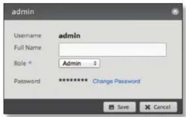
-
Username The unique account name is displayed.
• Full Name Enter the actual name of the user.
• Role Select the appropriate permission level: -
Admin The user can make changes to the EdgeRouter configuration.
- Operator The user can view the EdgeRouter configuration but cannot make changes.
- Password Click Change Password to make a change.
- Password Enter the new password.
- Confirm Enter the new password again.
- Cancel Change Password Click this option to cancel.

Click Save to apply your changes, or click Cancel.
Remote
Remote access of the EdgeRouter is logged on this tab.

Search Allows you to search for specific text. Begin typing; there is no need to press enter. The results are filtered in real time as soon as you type two or more characters.
PPTP/L2TP/PPPOE/All Click the appropriate tab to filter the remote users as needed.
- PPTP All users who use PPTP (Point-to-Point Tunneling Protocol) connections are displayed.
• L2TP All users who use L2TP (Layer 2 Tunneling Protocol) connections are displayed. - PPPOE All users who use PPPOE (Point-to-Point over Ethernet) connections are displayed.
- All All remote users are displayed by default.
A table displays the following information about each remote user. Click a column heading to sort by that heading.
Name The actual name of the user is displayed.
Type The type of connection used by the user is displayed.
Time The duration of the user's access is displayed.
Interface The specific interface used by the user is displayed.
Remote IP The remote IP address of the user is displayed.
TX packets The number of packets transmitted is displayed.
TX bytes The number of bytes transmitted is displayed.
RX packets The number of packets received is displayed.
RX bytes The number of bytes received is displayed.

Chapter 8: Wizards Tab
The Wizards tab allows you to access any available wizards:
- Setup Wizards
- WAN+2LAN (see the next column)
- Feature Wizards
• "Port Forwarding" on page 40
• "TCP MSS Clamping" on page 41 - "UPnP" on page 41
Setup Wizards
The WAN+2LAN setup wizard will guide you through a typical Small Office Home Office (SOHO) deployment:
- Configures the Internet connection and NAT masquerade for the Internet port
- Enables default firewall settings for the Internet port
- Enables DHCP server functionality for local networks
• Automatically enables DNS (Domain Name System) forwarding for local networks
• Automatically enables TCP MSS (Maximum Segment Size) clamping for a PPPoE (Point-to-Point over Ethernet) connection
If the EdgeRouter is already configured, then the WAN+2LAN setup wizard is not available. It is available only if the EdgeRouter uses its default configuration.
You can reset the EdgeRouter to its factory defaults using the EdgeOS Configuration Interface:
System Tab Refer to "Reset Config to Default" on page 7 for instructions.
Wizards Tab Click the WAN+2LAN setup wizard in the column on the left. The following window will appear.

Click Reset to Default Configuration and then follow the on-screen instructions.
WAN+2LAN
Click the WAN+2LAN setup wizard to begin the SOHO configuration.
Go to the section for your EdgeRouter model:
- ERLite-3, ER-8, and ERPro-8 See "ERLite-3, ER-8, ERPro-8" on page 38.
- ERPoe-5 See "ERPoe-5" on page 39.

Note: The WAN+2LAN setup wizard is designed to set up a basic SOHO network. For full configuration functionality, use the other tabs of the EdgeOS Configuration Interface or the Command Line Interface (CLI).
ERLite-3, ER-8, ERPro-8
LAN port (eth0)
Connect eth0 to your local network, such as a switch.

Address The IP address is displayed in the first field, and the subnet mask or prefix length is displayed in the second field.
DHCP Select this checkbox to have the EdgeRouter assign IP addresses.
Internet port (eth1)
Connect eth1 to your Internet connection.
Internet connection type Select the Internet connection type your network is using.
- DHCP Select this option if your Internet Service Provider (ISP) automatically assigns network settings to your network.

- Static IP Select this option if your ISP has assigned static network settings to your network.
- Address Enter the IP address in the first field and the subnet mask or prefix length in the second field.
- Gateway Enter the IP address of the ISP's gateway server, which provides the point of connection to the Internet.
- DNS server Enter the IP address of the ISP's DNS server.
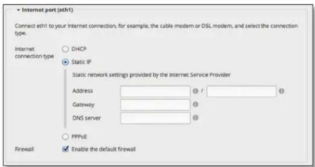
- PPPoE Select this option if your ISP uses PPPoE.
- Account Name Enter the name of your PPPoE account.
- Password Enter the password of your PPPoE account.

Firewall Enabled by default. This option applies the default firewall settings to the EdgeRouter; only established and related traffic types are allowed for local and inbound traffic.

(Optional) Secondary LAN port (eth2)
Click configure this section if you connect eth2 to your devices and/or a switch.
Address The IP address is displayed in the first field, and the subnet mask or prefix length is displayed in the second field.
DHCP Select this checkbox to have the EdgeRouter assign IP addresses.

Click Apply to apply your changes, or click Cancel.
ERPoe-5
Optional Secondary LAN port (eth0)
Click configure this section if you connect eth0 to your secondary local network.
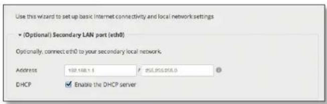
Address The IP address is displayed in the first field, and the subnet mask or prefix length is displayed in the second field.
DHCP Select this checkbox to have the EdgeRouter assign IP addresses.
Internet port (eth1)
Connect eth1 to your Internet connection.
Internet connection type Select the Internet connection type your network is using.
- DHCP Select this option if your ISP automatically assigns network settings to your network.
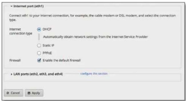
- Static IP Select this option if your ISP has assigned static network settings to your network.
- Address Enter the IP address in the first field and the subnet mask or prefix length in the second field.
- Gateway Enter the IP address of the ISP's gateway server, which provides the point of connection to the Internet.
- DNS server Enter the IP address of the ISP's DNS server.

- PPPoE Select this option if your ISP uses PPPoE.
- Account Name Enter the name of your PPPoE account.
- Password Enter the password of your PPPoE account.

Firewall Enabled by default. This option applies the default firewall settings to the EdgeRouter; only established and related traffic types are allowed for local and inbound traffic.

LAN ports (eth2, eth3, and eth4)
Click configure this section if you connect eth2, eth3, and/or eth4 to your devices and/or a switch. (The eth2, eth3, and/or eth4 become switch ports for a local network.)
Address The IP address is displayed in the first field, and the subnet mask or prefix length is displayed in the second field.
DHCP Select this checkbox to have the EdgeRouter assign IP addresses.
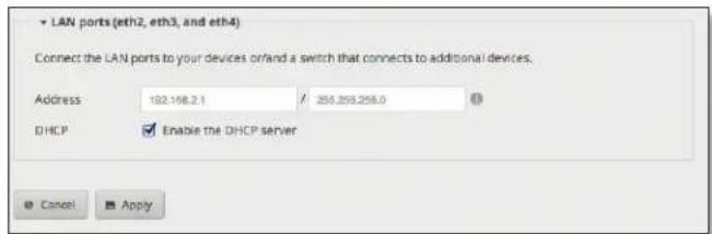
Click Apply to apply your changes, or click Cancel.
Feature Wizards
Each wizard will guide you through configuration of the corresponding feature: port forwarding, TCP MSS clamping, or UPnP.
Port Forwarding
Typically you configure a port forwarding rule so a host on the external network can access a server on the internal network by using the public IP address (or hostname) of the EdgeRouter.
Click the Port Forwarding feature wizard to begin configuration.
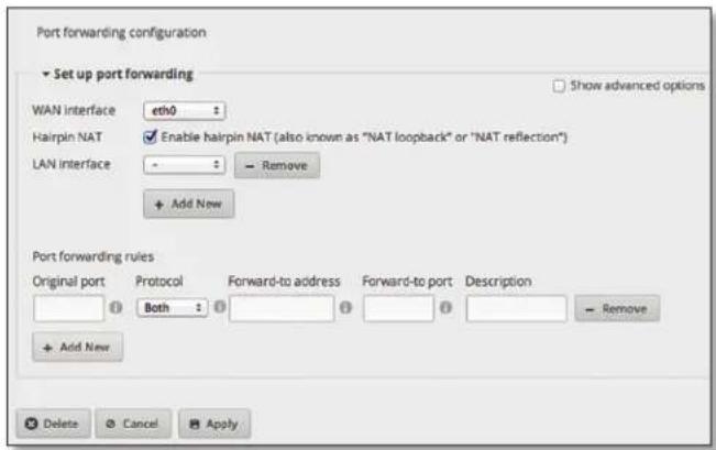
Set Up Port Forwarding
Show advanced options Select this checkbox to display the Auto firewall option.
WAN interface Select the appropriate interface from the drop-down menu. (If you select Other, then enter the interface name in the field provided.)
Hairpin NAT Enabled by default. If you want to allow a host on the internal network to use the public IP address to access an internal server, then keep Hairpin NAT enabled. (Hairpin NAT is also known as NAT loopback or NAT reflection.)

Note: If Hairpin NAT is enabled, then it only enables Hairpin NAT for the port forwarding rules defined in the wizard; it does not affect the Destination NAT Rules defined on the Security > NAT tab (refer to "Destination NAT Rules" on page 26).
Auto firewall Enabled by default. The Auto firewall option is displayed if Show advanced options is enabled. If you want the EdgeRouter to automatically open ports for the specified port forwarding rules, then keep Auto firewall enabled.
If you disable the Auto firewall option, then you will need to manually define firewall rules on the Security > Firewall Policies tab (refer to "Firewall Policies" on page 20).
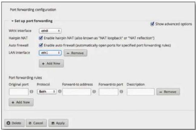
LAN interface Click Add New to display the drop-down menu. Then select the appropriate interface. (If you select Other, then enter the interface name in the field provided.)
- Remove Click to delete an interface.
- Add New Click to add another new interface.
Port Forwarding Rules
Add New Click to create a new rule.
- Original port Enter the port or ports that will be forwarded to the LAN. You can identify the port or ports by name, number, and/or range. To specify multiple ports, use a comma-separated list.
Example: https,20-23,554
- Protocol Enter the protocol that will be forwarded to the LAN: Both, TCP, or UDP.
- Forward-to address Enter the LAN IP address that will receive the forwarded port traffic.
- Forward-to port Enter the port or ports that will receive the forwarded port traffic. You can identify the port or ports by name, number, and/or range. If you do not specify the Forward-to port, then the original destination port of the traffic will be used.
• Description Enter keywords that will identify this rule. - Remove Click to delete a rule.
- Add New Click to create a new rule.
Click Apply to apply your changes, or click Cancel. To remove the entire port forwarding configuration created by the wizard, click Delete.
TCP MSS Clamping
TCP MSS (Maximum Segment Size) clamping is typically used when Path MTU Discovery is not working properly. Using ICMP messages, Path MTU Discovery determines the highest allowable MTU (Maximum Transmission Unit) of traffic traveling between two hosts to avoid fragmentation.
TCP uses MSS, which is the MTU minus the IP and TCP headers. The sender should limit its data so it does not exceed the MSS reported by the receiver.
Sometimes security firewalls or other issues interfere with the Path MTU Discovery process (for example, ICMP messages are blocked), so you can use a workaround, TCP MSS clamping, which sets the MSS value for all TCP connections.
Click the TCP MSS Clamping feature wizard to begin configuration.
TCP MSS Clamping
Enable MSS clamping for TCP connections Select this option to specify the MSS value for TCP connections.
Interface Types You can select which interface types use MSS clamping; PPPoE and PPTP are enabled by default.
MSS Enter the MSS value to use; 1412 is the default.

Click Apply to apply your changes, or click Cancel.
UPnP
Instead of manually configuring port forwarding rules, you can use UPnP for automatic port forwarding when you have hardware that supports UPnP.
Click the UPnP feature wizard to begin configuration.
Set Up UPnP Interfaces
Add New Click to create a new UPnP interface.
- Internal interface Select the appropriate LAN interface from the drop-down menu. (If you select Other, then enter the interface name in the field provided.)
- External interface Select the appropriate WAN interface from the drop-down menu. (If you select Other, then enter the interface name in the field provided.)
- Remove Click to delete a UPnP interface.
- Add New Click to create another new UPnP interface.

Click Apply to apply your changes, or click Cancel.

bar
| Port | Trx Rate (Kbps) | Rx Rate (Kbps) | | :--- | :--- | :--- | | eth0 | 45 | 12 | | eth1 | 48 | 13 | | eth1,100 | 50 | 14 | | eth2 | 47 | 11 | | eth3 | 46 | 10 | | eth4 | 49 | 12 | | eth5 | 48 | 11 | | eth6 | 47 | 10 | | eth7 | 46 | 9 | | eth8 | 49 | 12 | | eth9 | 50 | 13 | | eth10 | 52 | 15 | | eth11 | 51 | 14 | | eth12 | 53 | 16 | | eth13 | 54 | 15 | | eth14 | 55 | 16 | | eth15 | 56 | 17 | | eth16 | 57 | 18 | | eth17 | 58 | 19 | | eth18 | 59 | 20 | | eth19 | 60 | 21 | | eth20 | 61 | 22 | | eth21 | 62 | 23 | | eth22 | 63 | 24 | | eth23 | 64 | 25 | | eth24 | 65 | 26 | | eth25 | 66 | 27 | | eth26 | 67 | 28 | | eth27 | 68 | 29 | | eth28 | 69 | 30 | | eth29 | 70 | 31 | | eth30 | 71 | 32 | | eth31 | 72 | 33 | | eth32 | 73 | 34 | | eth33 | 74 | 35 | | eth34 | 75 | 36 | | eth35 | 76 | 37 | | eth36 | 77 | 38 | | eth37 | 78 | 39 | | eth38 | 79 | 40 | | eth39 | 80 | 41 | | eth40 | 81 | 42 | | eth41 | 82 | 43 | | eth42 | 83 | 44 | | eth43 | 84 | 45 | | eth44 | 85 | 46 | | eth45 | 86 | 47 | | eth46 | 87 | 48 | | eth47 | 88 | 49 | | eth48 | 89 | 50 | | eth49 | 90 | 51 | | eth50 | 91 | 52 | | eth51 | 92 | 53 | | eth52 | 93 | 54 | | eth53 | 94 | 55 | | eth54 | 95 | 56 | | eth55 | 96 | 57 | | eth56 | 97 | 58 | | eth57 | 98 | 59 | | eth58 | 99 | 60 | | eth59 | 100 | 61 | | eth60 | 101 | 62 | | eth61 | 102 | 63 | | eth62 | 103 | 64 | | eth63 | 104 | 65 | | eth64 | 105 | 66 | | eth65 | 106 | 67 | | eth66 | 107 | 68 | | eth67 | 108 | 69 | | eth68 | 109 | 70 | | eth69 | 110 | 71 | | eth70 | 111 | 72 | | eth71 | 112 | 73 | | eth72 | 113 | 74 | | eth73 | 114 | 75 | | eth74 | 115 | 76 | | eth75 | 116 | 77 | | eth76 | 117 | 78 | | eth77 | 118 | 79 | | eth78 | 119 | 80 | | eth79 | 120 | 81 | | eth80 | 121 | 82 | | eth81 | 122 | 83 | | eth82 | 123 | 84 | | eth83 | 124 | 85 | | eth84 | 125 | 86 | | eth85 | 126 | 87 | | eth86 | 127 | 88 | | eth87 | 128 | 89 | | eth88 | 129 | 90 | | eth89 | 130 | 91 | | eth90 | 131 | 92 | | eth91 | 132 | 93 | | eth92 | 133 | 94 | | eth93 | 134 | 95 | | eth94 | 135 | 96 | | eth95 | 136 | 97 | | eth96 | 137 | 98 | | eth97 | 138 | 99 | | eth98 | 139 | 100 | | eth99 | 140 | nanolimits are not yet written.Chapter 9: Toolbox
Each tab of the EdgeOS interface contains network administration and monitoring tools. At the top right of the screen, click the Toolbox ▶ Toolbox ▶ button. The Toolbox drop-down menu appears.

The following tools are available:
- Ping
- Trace
- Discover
- Packet Capture
- Log Monitor
Ping
You can ping other devices on the network directly from the EdgeRouter. The Ping tool uses ICMP packets to check the preliminary link quality and packet latency estimation between two network devices.

Destination Host/IP Enter the IP address.
Packet Count Enter the number of packets to send for the ping test.
Packet Size Specify the size of the packet.
Run Test Click this button to start the test.
Packet loss statistics and latency time evaluation are displayed after the test is completed.
Trace
The Trace tool traces the hops from the EdgeRouter to a specified outgoing IP address. Use this tool to find the route taken by ICMP packets across the network to the destination host.
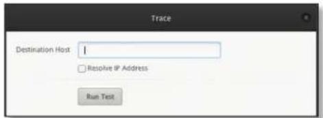
Destination Host Enter the IP address of the destination host.
Resolve IP Address Select this option to resolve the IP addresses symbolically (as names) instead of numerically.
Run Test Click this button to start the test.
Responses are displayed after the test is completed.
Discover
The Discover tool searches for all Ubiquiti devices on your network. The Search field automatically filters devices containing specified names or numbers as you enter them.

All/eth_ Select which interface to search, or select All.
The tool reports the number of Discovered and Displayed Ubiquiti devices. A table displays the following information about each Ubiquiti device. Click a column heading to sort by that heading.
Interface The EdgeRouter interface used by the device is displayed.
Hardware Address The MAC address of the device is displayed.
Device Name The name assigned to the device is displayed.
Product Name The Ubiquiti name of the device is displayed.
IP Address The IP address of the device is displayed. You can click it to access the device's configuration through its web management interface.
For more information, click the ▶ arrow to view the following:
- Firmware Version The version number of the device's firmware is displayed.
- Uptime The duration of the device's activity is displayed.
- Addresses The addresses of the device's interface are displayed. If the device has more than one interface, addresses for each interface are displayed.
- hwaddr The MAC address of the device's interface is displayed.
- ipv4 The IP address of the device's interface is displayed.
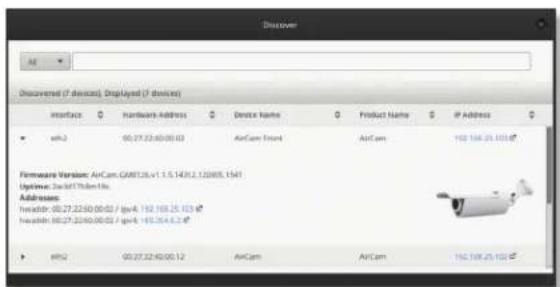
Packet Capture
Capture packets traveling through the specified interface for analysis. You can set up filters to capture the specific types of packets you are seeking.

Interface Enter the name of the interface.
Packet Limit Enter the number of packets to capture. The maximum number is 300.
Resolve addresses Select this option to resolve the IP addresses symbolically (as names) instead of numerically.
Filter
- Protocol Enter the protocol to filter.
- Address Enter the address to filter.
- Port Enter the port number to filter.
- Negate filter Check this box to capture all packets except for the ones matching the selected filter(s).
™ User Guide
Chapter 9: ToolboxEdgeOS
Start Click this button to start the capture. (If a Packet Limit is not specified, then this button becomes a Stop button during the capture.)
Capture results are displayed with Time and Packet descriptions.
Log Monitor
The Log Monitor is a log displaying live updates.
![System Log Monitor System log messages Time Message Oct 1 21:32:06 UBNT-OC zebra[384]: warning: interface eth1 broadcast addr 255.255.255.255.261* calculated 24.43.103.255, routing protocols may malfunction Jun 1 10:00:35 UBNT-OC dhcp: WARNING: Host declarations are global. They are not limited to the scope you declared them in. Jun 1 10:00:35 UBNT-OC dhcp: Jun 1 10:00:35 UBNT-OC dhcp: No subnet declaration for eth1 034.43.103.194.](/content/2026/05/869061/images/bcb9fbdb49cf98cab5c9f585681b5923fe67e332247cdc3f4601eb0ed3848569.jpg)
Click the pause button to stop the live updates. Click the play button to resume the live updates.
The System log messages table displays the following information about each log. Click a column heading to sort by that heading.
Time The system time is displayed next to every log entry that registers a system event.
Message A description of the system event is displayed.
Appendix A: Command Line Interface
Overview
The Command Line Interface (CLI) is available if you need to configure and monitor advanced features on the EdgeRouter or prefer configuration by command line. The CLI provides direct access to standard Linux tools and shell commands. This chapter explains how to access the CLI and describes a basic set of frequently used commands. Additional information is available on our website at: community.ubnt.com/edgemax
Access the CLI
There are four methods you can use to access the CLI:
• terminal emulator Go to the following section, Connect to the Console Port.
- SSH If you are using the console port, go to the following section, Connect to the Console Port; otherwise, go to "Access Using SSH" on page 46.
- Telnet If you are using the console port, go to the following section, Connect to the Console Port; otherwise, go to "Access Using Telnet" on page 46.
- EdgeOS Configuration Interface Go to "Access Using the EdgeOS Configuration Interface" on page 47.
Connect to the Console Port
Instructions may vary slightly, depending on your specific terminal emulator.
- Use a RJ45-to-DB9, serial console cable, also known as a rollover cable, to connect the Console port of the EdgeRouter to your computer. (If your computer does not have a DB9 port, then you will also need a DB9 adapter.)
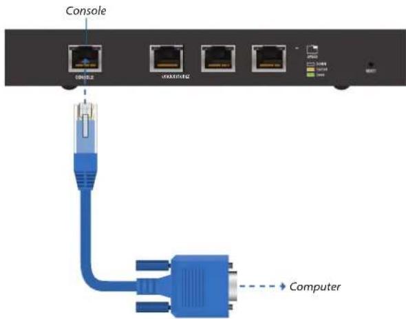
- Follow the appropriate set of instructions:
• terminal emulator Go to the following section, Access Using a Terminal Emulator.
- SSH Go to "Access Using SSH" on page 46.
- Telnet Go to "Access Using Telnet" on page 46.
Access Using a Terminal Emulator
Instructions may vary slightly, depending on your specific terminal emulator.
- Open the terminal emulator on your computer, and configure it with the following serial port settings:
• Baud rate 115200
- Data bits 8
- Parity NONE
- Stop bits 1
- Flow control NONE
- Select Serial as the connection type.
- Click Open to connect to the EdgeRouter.
- At the ubnt login prompt, enter the username (the default is ubnt).

- At the Password prompt, enter the password (the default is ubnt).
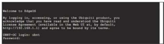
- For help with commands, you can either press the ? key or enter show and press the ? key.


Note: To enhance security, we recommend that you change the default login using one of the following:
- Set up a new user account (preferred option). For details, go to "Remove the Default User Account" on page 49.
- Change the default password of the ubnt login. Use the set command as detailed in "Remove the Default User Account" on page 49.
Access Using SSH
SSH is enabled by default.
- Open the SSH client on your computer.
- At the login prompt, enter:
ssh
The defaults are ubnt for the username and 192.168.1.1 for the hostname. You can also enter a domain name instead of an IP address for the hostname.


Note: Upon initial login, a host key will be displayed. You will be asked to confirm that you want to save the host key to the local database. Click Yes to bypass this message in the future.
- At the Password prompt, enter the password (the default is ubnt).
![Last Logs Have Oct 3:12:01:31 on https://www.bosch.com.cn Bosch@bosch.net is not https://www.bosch.com.cn The authenticity of the book: [00:168.1.1] "can't be established. USA key fingerprint is 00:00:00:00:00:00:00:00:00:00:00:00:00:00:00:00:00:00:00:00:00:00:00:00:00:00:00:00:00:00:00:00:00:00: 123-124-125-126-127-128-129-130-131-132-133-134-135-136-137-138-139-140-141-142-143-144-145-146-147-148-149-150-151-152-153-154-155-156-157-158-159-160-161-162-163-164-165-166-167-168-169-170-171-172-173-174-175-176-177-178-179-180-181-182-183-184-185-186-187-188-189-190-191-192-193-194-195-196-197-198-199-200-201-202-203-204-205-206-207-208-209-210-211-212-213-214-215-216-217-218-219-220-221-222-223-224-225-226-227-228-229-230-231-232-233-234-235-236-237-238-239-240-241-242-243-244-245-246-247-248-249-250-251-252-253-254-255-256-257-258-259-260-261-262-263-264-265-266-267-268-269-270-271-272-273-274-275-276-277-278-279-280-281-282-283-284-285-286-287-288-289-290](/content/2026/05/869061/images/e93721e939bd9f62ea1d2afc36763ddcd720b499945cb176668cee0abcaaa955.jpg)
- For help with commands, you can either press the ? key or enter show and press the ? key.
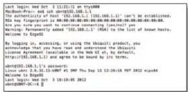

Note: To enhance security, we recommend that you change the default login using at least one of the following options:
- Set up a new user account (preferred option). For details, go to "Remove the Default User Account" on page 49.
- Change the default password of the ubnt login. Use the set command as detailed in "Remove the Default User Account" on page 49.
Access Using Telnet
Telnet is disabled by default. To use Telnet, enable it on the System tab (see "Telnet Server" on page 6).
- Open the telnet client on your computer.
- At the prompt, enter:
telnet
The default is 192.168.1.1 for the hostname. You can also enter a domain name instead of an IP address for the hostname.

- At the login prompt, enter the username (the default is ubnt).
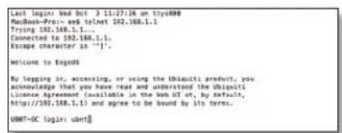
- At the Password prompt, enter the password (the default is ubnt).

- For help with commands, you can either press the ? key or enter show and press the ? key.


Note: To enhance security, we recommend that you change the default login using at least one of the following options:
- Set up a new user account (preferred option). For details, go to "Remove the Default User Account" on page 49.
- Change the default password of the ubnt login. Use the set command as detailed in "Remove the Default User Account" on page 49.
Access Using the EdgeOS Configuration Interface
Each tab of the EdgeOS interface contains CLI access.
- At the top right of the screen, click the CLI □cu button.
- The CLI window appears. At the login prompt, enter the username (the default is ubnt).

- At the Password prompt, enter the password (the default is ubnt).

- For help with commands, you can either press the ? key or enter show and press the ? key.


Note: To enhance security, we recommend that you change the default login using at least one of the following options:
- Set up a new user account (preferred option). For details, go to "Remove the Default User Account" on page 49.
- Change the default password of the ubnt login. Use the set command as detailed in "Remove the Default User Account" on page 49.
CLI Modes
Operational Mode
When you first log in, the CLI is in operational mode. Press the ? key to view the available commands.
ubnt@ubnt:\~\$

Note: The question mark does not display onscreen.
add delete ping6 reset terminal clear disconnect reboot restart traceroute configure generate release set traceroute6 connect initial-setup remove show undebug copy no rename shutdown debug ping renew telnet
Enter show and press the ? key to view the settings that you have configured.
ubnt@ubnt:-\$ show
| arp | flow-accounting nat | tech-support | |
| bridge | hardware ntp | ubnt | |
| configuration | history | openvpn users | |
| date | host | pppoe-server version | |
| debugging | incoming queueing | vpn | |
| dhcp | interfaces reboot | vrrp | |
| dhcpv6 | ip | route-map | webproxy |
| disk | ipv6 | shutdown | zebra |
| dns | lldp | snmp | |
| file | log | system | |
| firewall | login | table | |
For example, type show interfaces to display the interfaces and their status information.
ubnt@ubnt:\~\$ show interfaces Codes: S - State, L - Link, u - Up, D - Down, A - Admin Down
| Interface | IP Address | S/L | Description |
| ---- | ---- | --- | ---- |
| eth0 | - | u/u | |
| eth1 | - | u/D | |
| eth2 | - | u/D | |
| lo | 127.0.0.1/8 u/u |
To properly shut down the EdgeRouter, use the shutdown command.
ubnt@ubnt:-\$ shutdown

WARNING: Use the shutdown command to properly shut down the EdgeRouter. An improper shutdown, such as disconnecting the EdgeRouter from its power supply, runs the risk of data corruption!
Configuration Mode
To switch to configuration mode, use the configure command.
ubnt@ubnt:\~\$ configure
[edit]
ubnt@ubnt#
For the show, set, and delete commands, you can press the ? key for help.
- set ? View the available commands.
• show ? View the settings that you have configured. (Because configurations vary, the list you see will differ from the sample list displayed below.) - delete? View the settings that you can delete.
Enter show and press the ? key.
ubnt@ubnt# show
firewall interfaces protocol service system [edit]
To display the available command completions, press the tab key.

Note: The tab does not display onscreen.
ubnt@ubnt# show
Possible completions:
firewall Firewall
interfaces Network interfaces
protocols Routing protocol parameters
service Services
system System parameters
The EdgeRouter uses three configurations:
- Working When you make changes to the working configuration, they are not applied until you commit the changes to the active configuration.
- Active When you commit changes to the active configuration, they are applied; however, the changes do not become part of the boot configuration until you save the changes to the boot configuration.
- Boot When the EdgeRouter reboots, it loads the boot configuration for use.
The following scenarios cover some of the most commonly used commands:
- Configure an Interface (see below)
- "Remove the Default User Account" on page 49
- "Create a Firewall Rule" on page 49
- "Manage the Configuration File" on page 52
Configure an Interface
To configure an interface, do the following:
- Assign an IP address and subnet mask
- Enter a description
Use the set, compare, commit, and save commands.
To configure an interface, use the set command.
ubnt@ubnt:\~\$ configure
[edit]
To view the possible completions for the eth0 address, enter set interfaces ethernet eth0 address and press the ? key.
ubnt@ubnt# set interfaces ethernet eth0 address Possible completions:
| x.x.x.x/x> | IP address and prefix length |
| <h:h:h:h:h:h:h:h/x> | IPv6 address and prefix length |
| dhcp | Dynamic Host Configuration Protocol |
| dhcpv6 | Dynamic Host Configuration Protocol for IPv6 |
[edit]
ubnt@ubnt# set interfaces ethernet eth0 address 10.1.1.80/23
[edit]
ubnt@ubnt# set interfaces ethernet eth0 description "production LAN"
These changes affect the working configuration, not the active configuration. To see what changes have been made to the working configuration, use the compare command:
ubnt@ubnt# compare
[edit interfaces ethernet eth0]
+address 10.1.1.2/24
+description "production LAN"
[edit]
To make the changes active, use the commit command:
ubnt@ubnt# commit
[edit]
If you reboot the EdgeRouter, the changes will be lost. To save these changes, use the save command to save the active configuration to the boot configuration.
ubnt@ubnt# save
Saving configuration to '/config/config.boot'...
Done
[edit]
ubnt@ubnt# exit
exit
ubnt@ubnt:\~\$
ubnt@ubnt:\~\$ show interfaces
Codes: S - State, L - Link, u - Up, D - Down, A - Admin Down
| Interface | IP Address | S/L | Description |
| ---- | ---- | --- | ---- |
| eth0 | 10.1.1.80/23 | u/u | production LAN |
| eth1 | - | u/D | |
| eth2 | - | u/D | |
| lo | 127.0.0.1/8 | u/u | |
| ::1/128 |
ubnt@ubnt:\$ ping 10.1.0.1
PING 10.1.0.1 (10.1.0.1) 56(84) bytes of data.
64 bytes from 10.1.0.1: icmp_req=1 ttl=64 time=0.460 ms 64 bytes from 10.1.0.1: icmp_req=2 ttl=64 time=0.407 ms ^C
--- 10.1.0.1 ping statistics ---
2 packets transmitted, 2 received, 0% packet loss, time 999 ms
rtt min/avg/max/mdev = 0.407/0.433/0.460/0.033 ms
Remove the Default User Account
To remove the default user account, do the following:
- Create a new user
- Log out of the default user account
- Log in with the new user account
- Delete the default user account
Use the set, commit, save, exit, and delete commands.
ubnt@ubnt:~$ configure
[edit]
ubnt@ubnt:# set system login user admin1 authentication plaintext-password admin1pass
[edit]
ubnt@ubnt:# commit
[edit]
ubnt@ubnt:# save
Saving configuration to '/config/config.boot'...
Done
[edit]
ubnt@ubnt:# exit
exit
ubnt@ubnt:~$ exit
logout

Welcome to Edge OS ubnt ttyS0
ubnt login: admin1
Password:
Linux ubnt 2.6.32.13-UBNT #1 SMP Fri Jun 8 09:48:31 PDT 2012 mips64
Welcome to EdgeOS
admin1@ubnt:~$ configure
[edit]
admin1@ubnt# delete system login user ubnt
[edit]
admin1@ubnt# commit
[edit]
admin1@ubnt# save
Saving configuration to '/config/config.boot'...
Done
[edit]
admin@ubnt# exit
exit
admin1@ubnt:~$
The plaintext password that you entered is converted to an encrypted password.
admin1@ubuntu:~$ configure
[edit]
admin1@ubuntu# show system login
user admin1 {
    authentication {
    encrypted-password
    1mv8ERQ1T$7xq/eUDwy/5And7nV.9r6.
    plaintext-password
    }
}
[edit]
admin1@ubuntu# exit
exit
admin1@ubuntu:~$
Create a Firewall Rule
To create a firewall rule, use the set or edit commands (both methods are described below). In addition, use the compare, discard, up, top, copy, and rename commands.
Create a firewall rule using the full syntax:
ubnt@ubnt:-$ configure
[edit]
ubnt@ubnt# set firewall name TEST default-action drop
[edit]
ubnt@ubnt# set firewall name TEST enable-default-log
[edit]
ubnt@ubnt# set firewall name TEST rule 10 description
"allow icmp"
[edit]
ubnt@ubnt# set firewall name TEST rule 10 action accept
[edit]
ubnt@ubnt# set firewall name TEST rule 10 protocol icmp
[edit]
To display uncommitted changes, use the compare command:
ubnt@ubnt# compare
[edit firewall]
+name TEST {
+ default-action drop
+ enable-default-log
+ rule 10 {
+ action accept
+ description "allow icmp"
+ protocol icmp
+ }
+}
[edit]
To undo uncommitted changes, use the discard command:
ubnt@ubnt# discard
Changes have been discarded
[edit]
ubnt@ubnt# compare
No changes between working and active configurations
[edit]
To create the same firewall rule while reducing the amount of repetition in the full syntax, use the edit command:
ubnt@ubuntu# edit firewall name TEST
[edit firewall name TEST]
ubnt@ubuntu#set default-action drop
[edit firewall name TEST]
ubnt@ubuntu# set enable-default-log
[edit firewall name TEST]
ubnt@ubuntu#edit rule 10
[edit firewall name TEST rule 10]
Press the ? or tab key to display options for the specified edit level.
ubnt@ubnt# set
action disable ipsec p2p source time
description fragment limit protocol sta
destination icmp log recent tcp
[edit firewall name TEST rule 10]
ubnt@ubnt# set description "allow icmp"
[edit firewall name TEST rule 10]
ubnt@ubnt# set action accept
[edit firewall name TEST rule 10]
ubnt@ubnt# set protocol icmp
[edit firewall name TEST rule 10]
To show changes within the edit level, use the compare command:
ubnt@ubnt# compare
[edit firewall name TEST rule 10]
+action accept
+description "allow icmp"
+protocol icmp
[edit firewall name TEST rule 10]
To move up an edit level, use the up command:
ubnt@ubuntu#up
[edit firewall name TEST]
ubuntu#compare
[edit firewall name TEST]
+default-action drop
+enable-default-log
+rule 10 {
+ action accept
+ description "allow icmp"
+ protocol icmp
+}
[edit firewall name TEST]
ubuntu#up
[edit firewall]
ubuntu#compare
[edit firewall]
+name TEST {
+ default-action drop
+ enable-default-log
+ rule 10 {
+ action accept
+ description "allow icmp"
+ protocol icmp
+ }
+}
[edit firewall]
To return to the top edit level, use the top command:
ubnt@ubnt# top
[edit]
ubnt@ubnt# compare
[edit firewall]
+name TEST{
+ default-action drop
+ enable-default-log
+ rule 10 {
+ action accept
+ description "allow icmp"
+ protocol icmp
+ }
+}
[edit]
To display the existing firewall rule, use the show firewall command:
ubnt@ubnt# show firewall
name WAN1_LOCAL {
    default-action drop
    rule 10 {
    action accept
    state {
    established enable
    related enable
    }
    }
    rule 20 {
    action drop
    state {
    invalid enable
    }
    }
    rule 30 {
    action accept
    destination {
    port 22
    }
    protocol tcp
    }
}
[edit]
To create a new firewall rule from an existing firewall rule, use the copy command.
ubnt@ubnt# edit firewall
[edit firewall]
ubnt@ubnt# copy name WAN1_LOCAL to name WAN2_LOCAL
[edit firewall]
ubnt@ubnt# commit
[edit firewall]
ubnt@ubnt#top
[edit]
ubnt@ubnt#show firewall
name WAN1_LOCAL {
    default-action drop
    rule 10 {
    action accept
    state {
    established enable
    related enable
    }
    }
    rule 20 {
    action drop
    state {
    invalid enable
    }
    }
    rule 30 {
    action accept
    destination {
    port 22
    }
    protocol tcp
    }
}
name WAN2_LOCAL {
    default-action drop
    rule 10 {
    action accept
    state {
    established enable
    related enable
    }
    }
    rule 20 {
    action drop
    state {
    invalid enable
    }
    }
    rule 30 {
    action accept
    destination {
    port 22
    }
    protocol tcp
    }
}
[edit]
To change the name of the new firewall rule, use the rename command.
ubnt@ubnt# edit firewall
[edit firewall]
ubnt@ubnt# rename name W[TAB]
WAN1_LOCAL WAN2_LOCAL
[edit firewall]
ubnt@ubnt# rename name WAN2_LOCAL to name WAN2_IN
[edit firewall]
ubnt@ubnt# commit
[edit firewall]
ubnt@ubnt# top
[edit]
ubnt@ubnt# show firewall name
name WAN1_LOCAL {
    default-action drop
    rule 10 {
    action accept
    state {
    established enable
    related enable
    }
    }
    rule 20 {
    action drop
    state {
    invalid enable
    }
    }
    rule 30 {
    action accept
    destination {
    port 22
    }
    protocol tcp
    }
}
name WAN2_IN {
    default-action drop
    rule 10 {
    action accept
    state {
    established enable
    related enable
    }
    }
    rule 20 {
    action drop
    state {
    invalid enable
    }
    }
    rule 30 {
    action accept
    destination {
    port 22
    }
    protocol tcp
    }
}
[edit]
ubnt@ubnt#
Manage the Configuration File
Typically, you use the save command to save the active configuration to disk ('config/config.boot'); however, you can also save the active configuration to a different file or remote server.
Enter save and press the ? key.
ubnt@RTR# save
Possible completions:
Done [edit]
Scenario: In the midst of the administrator changing an IPsec tunnel into an OpenVPN tunnel, the administrator had to revert the EdgeRouter to its previous configuration with the IPsec tunnel.
- Before making changes, the administrator saved a backup configuration file with a working IPsec tunnel configuration:
ubnt@RTR# save config.boot-ipsec Saving configuration to '/config/config.boot-ipsec'... Done [edit]

Note: This is a backup; if the EdgeRouter were rebooted, it would still boot from the default file: '/config/config.boot'
- After the administrator deleted the IPsec configuration and was configuring of the OpenVPN tunnel, circumstances changed so that the IPsec tunnel was required again. Consequently, the administrator reverted the EdgeRouter to its previous configuration with the IPsec tunnel.
ubnt@RTR# load config.boot-ipsec
Loading configuration from
'/config/config.boot-ipsec'...
Load complete. Use 'commit' to make changes active. [edit] ubnt@RTR# commit [edit] ubnt@RTR# save; exit Saving configuration to '/config/config.boot'... Done exit ubnt@RTR:~$
To automatically make a remote backup after every commit, use the commit-archive configuration option, enter location, and press the ? key.
ubnt@RTR# set system config-management commit-archive location
Possible completions:
Detailed information:
"scp://
"ftp://
"tftp://
ubnt@RTR# set system config-management commit-archive location tftp://10.1.0.15/RTR
[edit]
ubnt@RTR# commit
Archiving config...
tftp://10.1.0.15/RTR OK
[edit]
On the remote tftp server, a copy with the hostname and date is saved for each commit.
admin2@server://tftpboot/RTR\$ ls -l
total 8
-rw---- 1 nobody nogroup 908 Aug 17 17:19
config.boot-RTR.20120817_171932
-rw---- 1 nobody nogroup 874 Aug 17 17:20
config.boot-RTR.20120818_002046
You can also keep a specified number of revisions of the configuration file on the local disk. Use the commit-revisions configuration option.
ubnt@RTR# set system config-management commit-revisions 50
[edit]
ubnt@RTR# commit
[edit]
Here is an example that uses the commit-revisions command:
ubnt@RTR# set system login user joe authentication plaintext-password secret
[edit]
ubnt@RTR# commit
[edit]
ubnt@RTR# save; exit
Saving configuration to '/config/config.boot'...
Done
exit
ubnt@RTR:-\$ show system commit
0 2012-08-17 18:32:13 by ubnt via cli commit
1 2012-08-17 18:31:52 by ubnt via cli commit
2 2012-08-17 18:31:51 by root via init commit

Note: The following commands require that the configuration option, commit-revisions, be set first.
show system commit diff commit-confirm
show system commit file confirm
show system commit rollback
commit comment
For details on the commit-revisions option, go to "Manage the Configuration File" on page 52.
To display the changes in revision 0, use the show system commit diff command.
ubnt@RTR:~$ show system commit diff 0
[edit system login]
+user joe {
+ authentication {
+ encrypted-password
1CWVzYggs$NyJXxC3S572rfm6pY8ZMO.
+ plaintext-password ""
+ }
+ level admin
+}
To display the entire configuration file for revision 0, use the show system commit file command.
ubnt@RTR:\~\$ show system commit file 0
To add a comment to the commit, use the comment command.
ubnt@RTR# set system login user joe level operator
[edit]
ubnt@RTR# commit comment "change joe from admin to op"
[edit]
ubnt@RTR# save; exit
Saving configuration to '/config/config.boot'...
Done
exit
Now you will see the comment when you use the show system commit command.
ubnt@RTR:\~\$ show system commit
0 2012-08-17 18:44:41 by ubnt via cli change joe from admin to op
1 2012-08-17 18:34:01 by ubnt via cli commit
2 2012-08-17 18:32:13 by ubnt via cli commit
3 2012-08-17 18:31:52 by ubnt via cli commit
4 2012-08-17 18:31:51 by root via init commit
When you work on a remote router, certain changes, such as a firewall or NAT rule, can cut off access to the remote router, so you then have to visit the remote router and reboot it. To avoid such issues when you make risky changes, use the commit-confirm command first. Then use the confirm command to save your changes.
ubnt@RTR:~$ configure
[edit]
ubnt@RTR# set firewall name WAN_IN rule 50 action drop
[edit]
ubnt@RTR# set firewall name WAN_IN rule 50 destination
address 172.16.0.0/16
[edit]
ubnt@RTR# commit-confirm
commit confirm will be automatically reboot in
10 minutes unless confirmed
Proceed? [confirm][y]
[edit]
After you verify that the changes should be saved, use the confirm command.
ubnt@RTR# confirm
[edit]
You can also specify the number of minutes to wait, but you must remember to also use the confirm command.
Otherwise, if you forget, then you can be surprised by the EdgeRouter's reboot to its previous configuration.
ubnt@RTR# commit-confirm 1
commit confirm will be automatically reboot in 1 minutes unless confirmed
Proceed? [confirm][y]
[edit]
ubnt@RTR#
Broadcast message from root@RTR (Mon Aug 20 14:00:06 2012):
The system is going down for reboot NOW!
INIT: Switching to runlevel: 6
INIT: Stopping routing services...zebra...done.
Removing all Quagga Routes.
[SNIP]
To roll back to an earlier commit, use the show system commit and rollback commands.
ubnt@RTR:\~\$ show system commit
0 2012-08-21 14:46:41 by admin_5 via cli fix bgp policy maps
1 2012-08-21 14:45:59 by admin_5 via cli commit
2 2012-08-21 14:45:33 by admin_5 via cli fix port forwarding
3 2012-08-21 14:45:15 by admin_5 via cli fix firewall
4 2012-08-21 14:44:29 by ubnt via cli commit
5 2012-08-21 14:21:15 by ubnt via cli add port forward for port 2222 to build-server
6 2012-08-21 14:20:24 by ubnt via cli add dmz interface to eth2
7 2012-08-21 14:19:53 by ubnt via cli add ipsec tunnel to office_exchange
8 2012-08-21 14:07:18 by ubnt via cli add firewall for WAN_IN
9 2012-08-21 14:06:37 by ubnt via cli add user first_last
10 2012-08-21 14:04:47 by ubnt via cli commit
11 2012-08-21 14:04:46 by root via init commit
After viewing the history of system commits, you decide to discard the last four commits by admin_5. Roll back the system configuration file to commit 4:
ubnt@RTR# rollback 4
Proceed with reboot? [confirm] [y]
Broadcast message from root@RTR (ttyS0) (Mon Aug 21 15:09:12 2012):
The system is going down for reboot NOW!
Appendix B: Contact Information
Ubiquiti Networks Support
Ubiquiti Support Engineers are located around the world and are dedicated to helping customers resolve software, hardware compatibility, or field issues as quickly as possible. We strive to respond to support inquiries within a 24-hour period.
Online Resources
Support: support.ubnt.com
Community: community.ubnt.com
Downloads: downloads.ubnt.com

2580 Orchard Parkway
San Jose, CA 95131
www.ubnt.com
© 2012-2014 Ubiquiti Networks, Inc. All rights reserved. Ubiquiti, Ubiquiti Networks, the Ubiquiti U logo, the Ubiquiti beam logo, EdgeMAX, EdgeOS, EdgeRouter, and UniFi are trademarks of Ubiquiti Networks, Inc. in the United States and in other countries. All other trademarks are the property of their respective owners.
- Table of Contents
- Chapter 1: Overview....1
- Chapter 2: Using EdgeOS....3
- Chapter 3: Dashboard Tab ....8
- Chapter 4: Routing Tab ....14
- Chapter 5: Security Tab....20
- Chapter 6: Services Tab 30
- Chapter 7: Users Tab ....35
- Chapter 8: Wizards Tab ....37
- Chapter 9: Toolbox ....42
- Appendix A: Command Line Interface 45
- Appendix B: Contact Information....54
- Chapter 1: Overview
- Introduction
- Configuration
- Configuration Interface System Requirements
- Hardware Overview and Installation
- Typical Deployment Scenarios
- SOHO Deployment
- Service Provider Deployment
- Corporate Deployment
- Chapter 2: Using EdgeOS
- Ports and Status Information
- Navigation
- Common Interface Options
- Welcome
- CLI
- Toolbox
- Alerts
- System
- Basic Settings
- Host Name
- Time Zone
- Gateway
- Name Server
- Domain Name
- NTP
- Management Settings
- SSH Server
- Telnet Server
- System Log
- SNMP Agent
- Configuration Management & Device Maintenance
- Back Up Config
- Restore Config
- Upgrade System Image
- Reset Config to Default
- Restart & Shut Down Router Restart Router
- Shut Down Router
- Chapter 3: Dashboard Tab
- Services
- Routes
- OSPF
- NAT
- Firewall
- DHCP
- Interfaces
- Distribution
- All/Ethernet/VLAN
- Configure the Interface
- Configure the VLAN
- Configure the Switch
- Configure the PoE Settings
- PoE Watchdog
- Chapter 4: Routing Tab
- IPv6 Routing
- All/Static/Connected/RIP/OSPF
- Configure the Static Route
- Interface
- Black Hole
- Router
- Redistribution
- Areas
- Configure the OSPF Area
- Add OSPF Interface To create a new interface, click Add OSPF Interface.
- Configure the OSPF Interface
- Chapter 5: Security Tab
- Firewall Policies
- All/Drop/Reject/Accept
- Configure the Firewall Policy
- Rules
- Add or Configure a Rule
- Basic
- Advanced
- Source
- Destination
- Time
- Stats
- Source NAT Rules
- Add Source NAT Rule To create a new rule, click Add Source NAT Rule. Go to "Add or Configure a Source NAT Rule" on page 25.
- Add or Configure a Source NAT Rule
- Destination NAT Rules
- Add or Configure a Destination NAT Rule
- Firewall/NAT Groups
- All/Address/Network/Port
- Configure the Firewall/NAT Group
- VPN
- PPTP Server
- Chapter 6: Services Tab
- DHCP Server
- Configure the DHCP Server
- Leases
- Static MAC/IP Mapping
- Configure Static MAC/IP Mapping
- Details
- DNS
- DNS Forwarding
- PPPoE
- PPPoE Server
- Chapter 7: Users Tab
- Local
- Configure the User
- Remote
- Chapter 8: Wizards Tab
- Setup Wizards
- WAN+2LAN
- ERLite-3, ER-8, ERPro-8
- LAN port (eth0)
- Internet port (eth1)
- (Optional) Secondary LAN port (eth2)
- ERPoe-5
- Optional Secondary LAN port (eth0)
- LAN ports (eth2, eth3, and eth4)
- Feature Wizards
- Port Forwarding
- Set Up Port Forwarding
- Port Forwarding Rules
- TCP MSS Clamping
- UPnP
- Set Up UPnP Interfaces
- Chapter 9: Toolbox
- Ping
- Trace
- Discover
- Packet Capture
- Filter
- Log Monitor
- Appendix A: Command Line Interface
- Overview
- Access the CLI
- Connect to the Console Port
- Access Using a Terminal Emulator
- Access Using SSH
- Access Using Telnet
- Access Using the EdgeOS Configuration Interface
- CLI Modes
- Operational Mode
- Configuration Mode
- Configure an Interface
- Remove the Default User Account
- Create a Firewall Rule
- Manage the Configuration File
- Appendix B: Contact Information
- Ubiquiti Networks Support
- Online Resources
Brand : Ubiquiti Networks
Model : EdgeOS 1.4
Category : Photo/Video Software