Garden Utility Cart RP-ALGE-M - Garden cart Gardenline - Free user manual and instructions
Find the device manual for free Garden Utility Cart RP-ALGE-M Gardenline in PDF.


| Product Type | Garden Utility Cart |
| Brand | Gardenline |
| Model | RP-ALGE-M |
| Load Capacity | 500 lbs (225 kg) |
| Maximum Tire Pressure | 30 PSI |
| Assembly Time | 20 minutes |
| Number of Wheels | 4 |
| Wheel Type | Pneumatic |
| Tools Required | 3/4" Adjustable Wrench, 1/2" Ratchet, Handheld Air Pump, Tire Pressure Gauge |
| Included Accessories | Removable Rubber Liner, Pull Handle, Plastic Coupling, Hardware Pack |
| Safety Warning 1 | Do not exceed 500 lbs load |
| Safety Warning 2 | Do not tow faster than 2 mph |
| Safety Warning 3 | Do not use on highways |
| Safety Warning 4 | Do not carry passengers |
| Safety Warning 5 | Not for use by children |
| Maintenance | Lubricate pivot bolt and bearings annually |
| Maintenance | Grease wheel bearings periodically |
| Maintenance | Check tire pressure regularly |
| Storage | Cover or store out of weather when not in use |
| Warranty | 3 Years |
Frequently Asked Questions - Garden Utility Cart RP-ALGE-M Gardenline
User questions about Garden Utility Cart RP-ALGE-M Gardenline
0 question about this device. Answer the ones you know or ask your own.
Ask a new question about this device
Download the instructions for your Garden cart in PDF format for free! Find your manual Garden Utility Cart RP-ALGE-M - Gardenline and take your electronic device back in hand. On this page are published all the documents necessary for the use of your device. Garden Utility Cart RP-ALGE-M by Gardenline.
USER MANUAL Garden Utility Cart RP-ALGE-M Gardenline
Safety information and Warnings 3
Preparation 3
Tools Needed 3
Package Contents 4
Hardware Contents 5
Assembly Instructions 6-9
Care and Maintenance 9
Exploding Assembly Drawing 10

SAFETY INFORMATION and WARNINGS
Please read, understand and follow ALL instructions and warnings in this owner's manual before using this product.
- Do NOT tow this cart on steep hills.
- Do NOT tow this cart faster than 2 mph.
- While towing, make slow turns to avoid damage to the cart and its contents.
- Do NOT exceed 30 PSI when inflating the tire(s) as damage to the tire(s) and/or personal injury could result.
- Do NOT load this cart with more than 500 lbs (225 kgs) of contents.
- Do NOT allow any children to use, play in, near, or around this cart. This is not a toy.
- This cart is NOT to be used for transporting passengers.
- This cart is NOT to be used for highway use.
• Always distribute the load evenly over the surface of the cart bed. - If any part of this cart becomes damaged, broken, or misplaced, do NOT use this cart until a replacement part has been obtained.
- Do NOT operate this cart on surfaces, or roll over objects that could cause damage to the pneumatic tires or tubes.
- Use only a hand-held air pump to inflate the tires.
- Save these instructions for future reference.
PREPARATION
Before beginning assembly of this product, make sure all parts are present. Compare parts with package contents listed in this booklet. If any part is missing or damaged, do not attempt to assemble this product. Contact customer service for replacement parts. Estimated assembly time: 20 minutes
TOOLS NEEDED
The following tools are needed for proper assembly:

3/4" Adjustable Wrench

1/2" Ratchet


Handheld Air Pump
Tire Pressure Gauge
Garden Utility Cart
PACKAGE CONTENTS
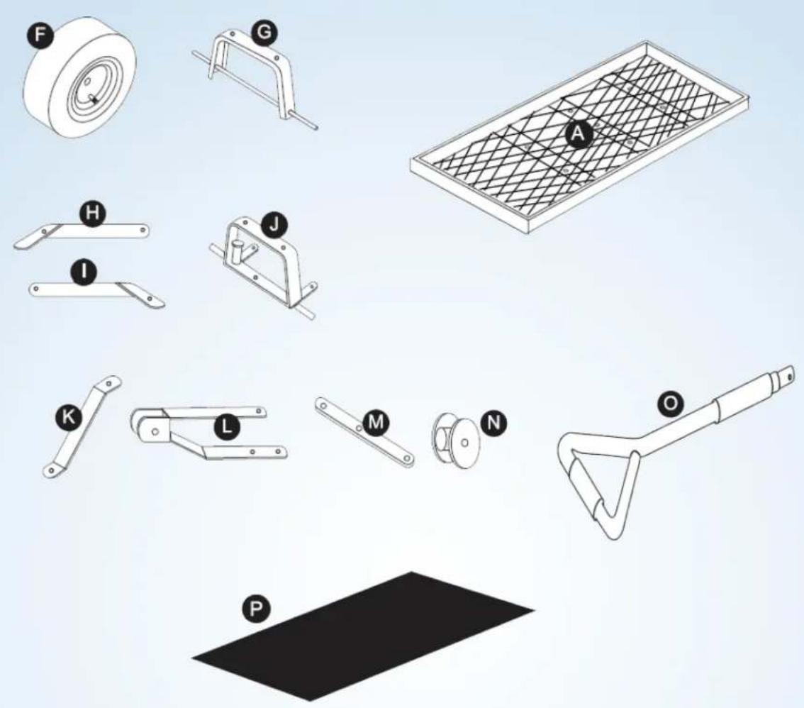
| Diagram Letter | Description Quantity | |
| A Cart | Bed 1 | |
| F Wheels | 4 | |
| G Rear | Axle Support 1 | |
| H Left | Rear Axle Brace 1 | |
| I Right | Rear Axle Brace 1 | |
| J Front | Axle Support 1 | |
| Diagram Letter | Description Quantity | |
| K | Center Front Axle Brace 1 | |
| L | Yoke 1 | |
| M | Steering Link Connector | 1 |
| N | Plastic Coupling | 1 |
| O | Pull Handle | 1 |
| P | Removable Rubber Liner | 1 |
Garden Utility Cart
HARDWARE CONTENTS

Large Lock Pins 1

natural_image
Simple line drawing of a curved pipe or tube with no text or symbols
8 mm Washers 8


8 mm Nuts with 7 Lock Inserts


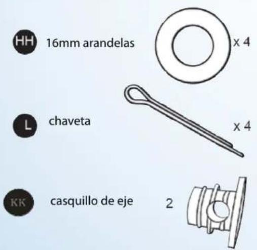
16 mm Washers 4


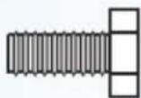
Carriage Support Bolts (used with parts # FF and GG) 7

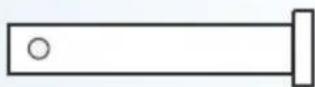
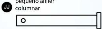
Small Columnar Pin 1

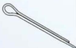
Cotter Pin 7

16mm small ring washer 2


Retainer Washer 1


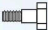
Short Steering Bolts (used with 3 parts # PP and QQ)

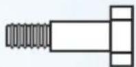
Long Steering Bolt (used with 1 parts # PP and QQ)

6 mm Lock Nuts 4


6 mm Washers 4


Axle cap 2

Garden Utility Cart
ASSEMBLY INSTRUCTIONS
- Turn the cart bed (A) upside down. If necessary, use the cardboard from the product carton to prevent scratching and damage to the finish of the cart.
2. REAR AXLE ASSEMBLY
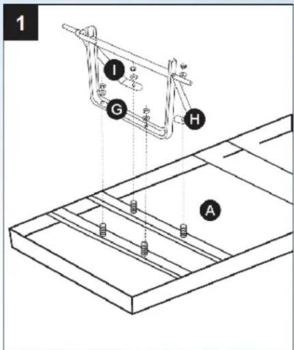
a). Align the two holes in the rear axle support (G) with the carriage support bolt (II) which were welded on the bed at the rear of the cart bed (A).
NOTE: The rear section of the cart has a total of 6 holes.
b). Attach an 8 mm washer (FF) and an 8 mm nut (GG) to the end of each bolt.
NOTE: Hand-tighten the connection. Do not tighten completely.
c). Insert the end of the left rear axle brace (H) onto the side of the rear axle support with the welded spacer bushings facing outward. Repeat this step for the right rear axle brace (I).
d). Align the holes on the flat ends of the left and right axle braces with carriage support bolts (II) which are welded on the bed of the cart.
NOTE: If you experience difficulty lining up the holes, loosen the bolts on the rear axle support until the holes on the braces align.
e). Attach an 8 mm washer (FF) and a 8mm nut (GG) to the ends of each bolt. (see figure 1).
NOTE: Once attached, tighten all bold connections from previous steps.
Hardware Used

8 mm Washers

× 4

8 mm Nuts with Lock Inserts

×4
Garden Utility Cart
ASSEMBLY INSTRUCTIONS - continued
3. FRONT AXLE ASSEMBLY
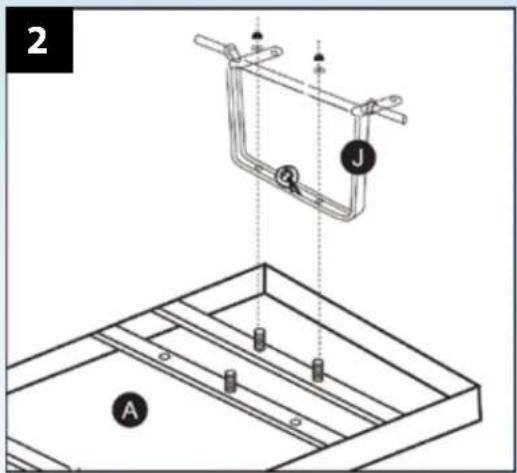
a). Attach the front axle support (J) to the bed (A) by using two carriage support bolts which are welded onto the bed and two 8 mm washers (FF) and two 8 mm lock nuts (GG). (see Fig. 2)
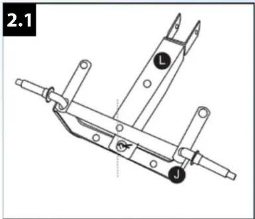
b). Attach the Yoke (L) to the front axle support (J) by using the retainer washer (MM) and cotter pin (L). (see Fig 2.1)
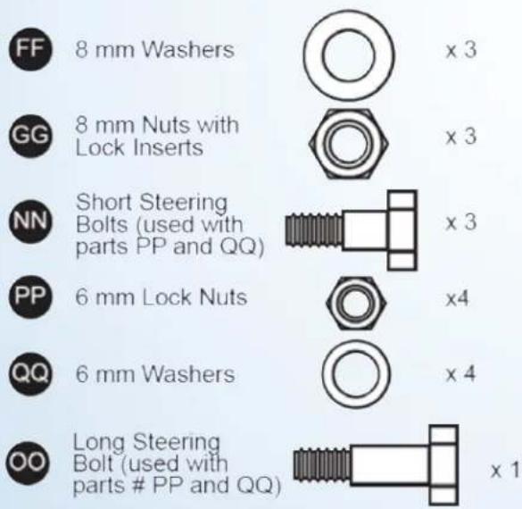
c). Attach the center front axle brace (K) and yoke (L) to the front axle support (J) by using long steering bolts (OO), 6 mm washers (QQ) and 6 mm lock nut (PP). (see Fig 2.2)
d). Attach the steering link connector (M) to the front axle support (J) and yoke (L) by using three short steering bolts (NN), 6mm washers (QQ) and 6 mm lock nuts (PP). (see Fig 2.2)
NOTE: Leave at least one full turn on each bolt connection to allow for smooth steering operation.
Hardware Used

Garden Utility Cart
ASSEMBLY INSTRUCTIONS - continued
4. WHEEL ASSEMBLY
a). Place the wheels (F) onto the ends of the front and rear axle supports.
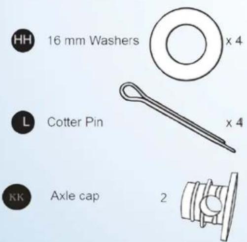
b). Insert a 12 mm washer (HH) and a Cotter Pin (LL) onto the end of each wheel. (see Fig. 3)
c). Put the axle cap (KK) into the end of the rear axle.

Hardware Used
Garden Utility Cart
ASSEMBLY INSTRUCTIONS - continued
5. PULL HANDLE ASSEMBLY
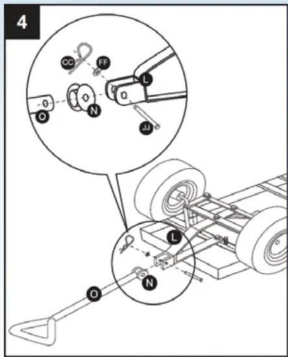
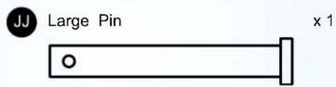
a). Remove the large pin (JJ) from the plastic coupling (N).
b). Insert the end of the pull handle (O) into the plastic coupling (N).
NOTE: Make certain the holes in the pull handle are aligned with the holes in the plastic coupling.
c). Place the pull handle (O) and plastic coupling (N) assembly into the yoke (L).
d). Align the holes in the pull handle and plastic coupling with the holes on the yoke.
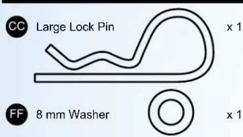
e). Insert the large pin (JJ) through the aligned holes and secure the connection with a washer (FF) and a lock pin (CC). (see Fig. 4)
Hardware Used
6. RUBBER MAT ASSEMBLY
a). Place the rubber mat (Q) onto the cart bed. This can be removed if not needed.
7. TIRE INFLATION
a). Before attempting to operate the cart, check the air pressure of each tire.
b). If additional inflation is needed, use only a hand-operated air pump
c). Do NOT exceed 30 PSI as damage to the tires and/or personal injury could result.
CARE AND MAINTENANCE
- Check for loose fasteners before use.
- At the beginning of each season lubricate the pivot bolt and bearings with light machine oil.
- Grease the wheel bearings periodically, using general purpose grease.
- Check tire pressure regularly and inflate if needed. Do not over inflate.
- Cover or store out of weather when not in use.
Garden Utility Cart
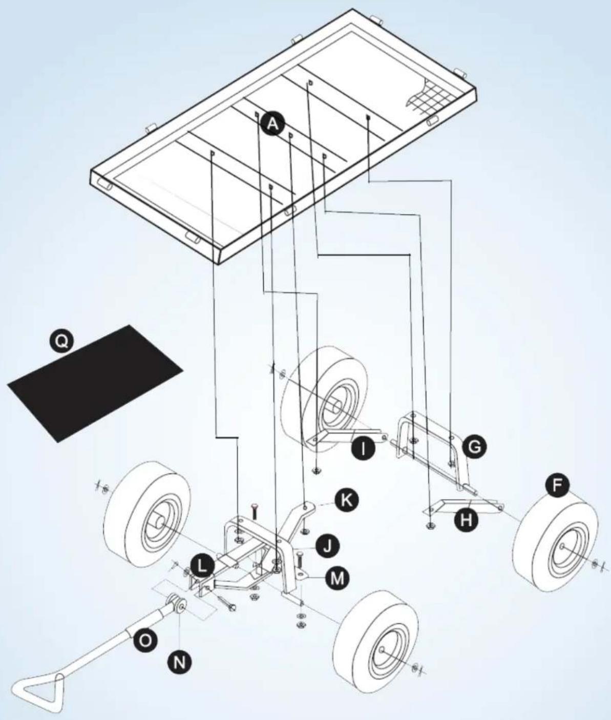
EXPLODING ASSEMBLY DRAWING

3/4" Llave ajustable

1/2" Ratchet

Hardware utilizado

arandelas de 8 mm

×4

natural_image
Technical line drawing of a mechanical clamp or bracket assembly (no text or symbols)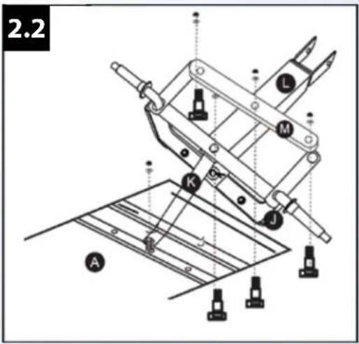
Hardware utilizado
x 1
6. GOMA MAT ASAMBLEA

DISTRIBUTED BY / DISTRIBUIDO POR:
ALDI INC. BATAVIA, IL 60510
WWW.ALDI.US
AFTER SALES SUPPORT • SERVICIO DE POSVENTA

USA
1-866-446-2063

GUARANTEED@RAYPADULA.COM
MODEL: RP-ALGE-M PRODUCT CODE: 52377 03/2017

YEAR WARRANTY AÑOS DE GARANTÍA


- SAFETY INFORMATION and WARNINGS
- Please read, understand and follow ALL instructions and warnings in this owner's manual before using this product.
- PREPARATION
- TOOLS NEEDED
- Garden Utility Cart
- HARDWARE CONTENTS
- ASSEMBLY INSTRUCTIONS
- REAR AXLE ASSEMBLY
- Hardware Used
- ASSEMBLY INSTRUCTIONS - continued
- FRONT AXLE ASSEMBLY
- WHEEL ASSEMBLY
- PULL HANDLE ASSEMBLY
- RUBBER MAT ASSEMBLY
- TIRE INFLATION
- CARE AND MAINTENANCE
- Hardware utilizado
- GOMA MAT ASAMBLEA
Brand : Gardenline
Model : Garden Utility Cart RP-ALGE-M
Category : Garden cart