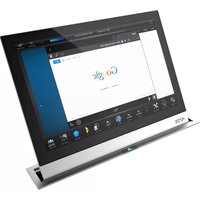
MXR-10010-SL - Touchscreen AMX - Free user manual and instructions
Find the device manual for free MXR-10010-SL AMX in PDF.


| Product Type | 10.1" Modero X Series G5 Retractable Touch Panel |
| Model Numbers | MXR-1001-BL (Black), MXR-1001-SL (Silver) |
| Dimensions (HxWxD) | 15.325 x 11.010 x 6.753 in (389.25 x 279.65 x 171.53 mm) |
| Cutout Dimensions | 10.701 x 1.984 in (271.81 x 50.39 mm) |
| Weight | 18.85 lbs (8.55 kg) |
| Power Consumption | Full-On (in motion): 15.6W, No motion: 7.2W, Sleep: 4.6W, Shutdown: 0.12W |
| Power Supply | 24VDC via included PSR2.5 external power supply |
| Touch Screen Technology | Projected capacitive, multi-touch (3 simultaneous max) |
| Display Resolution | 1280 x 800 (WXGA) |
| Display Brightness | 400 cd/m² |
| Contrast Ratio | 700:1 |
| Viewing Angle | ±89° vertical and horizontal |
| Memory | SDRAM: 2 GB, Flash: 16 GB, Max project size: 12 GB |
| Communications | Ethernet 10/100, USB 2.0 (2 ports), NFC, Bluetooth (with optional adapter) |
| Operating Temperature | 32°F to 104°F (0°C to 40°C) |
| Storage Temperature | 4°F to 140°F (-20°C to 60°C) |
| Motorized Mechanism | Raise/lower via pushbutton or NetLinx control with pinch protection and audio alert |
| Included Accessories | PSR2.5 power supply, mounting screws (11), clamps (4), cutout template, spacer, USB port cover kit, cleaning kit |
| Optional Accessories | Router guide, Bluetooth adapter, handset, PoE switch |
| Certifications | FCC Part 15 Class B, IC/CSA, CE, UL 60950-1, RoHS/WEEE/ErP |
Frequently Asked Questions - MXR-10010-SL AMX
User questions about MXR-10010-SL AMX
0 question about this device. Answer the ones you know or ask your own.
Ask a new question about this device
Download the instructions for your Touchscreen in PDF format for free! Find your manual MXR-10010-SL - AMX and take your electronic device back in hand. On this page are published all the documents necessary for the use of your device. MXR-10010-SL by AMX.
USER MANUAL MXR-10010-SL AMX
INSTALLATION & HARDWARE REFERENCE MANUAL
MODERO X ® SERIES G5 RETRACTABLE TOUCH PANELS
MXR-1001-BL 10.1" MODERO X SERIES G5 RETRACTABLE TOUCH PANEL (BLACK)
MXR-1001-SL 10.1" MODERO X SERIES G5 RETRACTABLE TOUCH PANEL (SILVER)
IMPORTANT SAFETY INSTRUCTIONS
-
READ these instructions.
-
KEEP these instructions.
-
HEED all warnings.
-
FOLLOW all instructions.
-
DO NOT use this apparatus near water.
-
CLEAN ONLY with dry cloth.
-
DO NOT block any ventilation openings. Install in accordance with the manufacturer's instructions.
-
DO NOT install near any heat sources such as radiators, heat registers, stoves, or other apparatus (including amplifiers) that produce heat.
-
DO NOT defeat the safety purpose of the polarized or grounding type plug. A polarized plug has two blades with one wider than the other. A grounding type plug has two blades and a third grounding prong. The wider blade or the third prong are provided for your safety. If the provided plug does not fit into your outlet, consult an electrician for replacement of the obsolete outlet.
-
PROTECT the power cord from being walked on or pinched, particularly at plugs, convenience receptacles, and the point where they exit from the apparatus.
-
ONLY USE attachments/accessories specified by the manufacturer.

-
USE ONLY with a cart, stand, tripod, bracket, or table specified by the manufacturer, or sold with the apparatus. When a cart is used, use caution when moving the cart/apparatus combination to avoid injury from tip-over.
-
UNPLUG this apparatus during lightning storms or when unused for long periods of time.
-
REFER all servicing to qualified service personnel. Servicing is required when the apparatus has been damaged in any way, such as power-supply cord or plug is damaged, liquid has been spilled or objects have fallen into the apparatus, the apparatus has been exposed to rain or moisture, does not operate normally, or has been dropped.
-
DO NOT expose this apparatus to dripping or splashing and ensure that no objects filled with liquids, such as vases, are placed on the apparatus.
-
To completely disconnect this apparatus from the AC Mains, disconnect the power supply cord plug from the AC receptacle.
-
Where the mains plug or an appliance coupler is used as the disconnect device, the disconnect device shall remain readily operable.
-
DO NOT overload wall outlets or extension cords beyond their rated capacity as this can cause electric shock or fire.

19) THERE IS RISK OF PINCH DURING OPERATION. Keep hands and objects clear while panel is raising or lowering. If a finger, or any object, gets caught in the moving mechanism pressing the button on the bezel one time will stop the movement. Pressing the button again will reverse the movement allowing the object to be easily removed.

The exclamation point, within an equilateral triangle, is intended to alert the user to the presence of important operating and maintenance (servicing) instructions in the literature accompanying the product.

The lightning flash with arrowhead symbol within an equilateral triangle is intended to alert the user to the presence of uninsulated "dangerous voltage" within the product's enclosure that may be of sufficient magnitude to constitute a risk of electrical shock to persons.

ESD Warning: The icon to the left indicates text regarding potential danger associated with the discharge of static electricity from an outside source (such as human hands) into an integrated circuit, often resulting in damage to the circuit.
WARNING: To reduce the risk of fire or electrical shock, do not expose this apparatus to rain or moisture.
WARNING: No naked flame sources - such as lighted candles - should be placed on the product.
WARNING: Equipment shall be connected to a MAINS socket outlet with a protective earthing connection.
CAUTION: To reduce the risk of electric shock, grounding of the center pin of this plug must be maintained.
COPYRIGHT NOTICE
AMX© 2017, all rights reserved. No part of this publication may be reproduced, stored in a retrieval system, or transmitted, in any form or by any means, electronic, mechanical, photocopying, recording, or otherwise, without the prior written permission of AMX. Copyright protection claimed extends to AMX hardware and software and includes all forms and matters copyrightable material and information now allowed by statutory or judicial law or herein after granted, including without limitation, material generated from the software programs which are displayed on the screen such as icons, screen display looks, etc. Reproduction or disassembly of embodied computer programs or algorithms is expressly prohibited.
LIABILITY NOTICE
No patent liability is assumed with respect to the use of information contained herein. While every precaution has been taken in the preparation of this publication, AMX assumes no responsibility for error or omissions. No liability is assumed for damages resulting from the use of the information contained herein. Further, this publication and features described herein are subject to change without notice.
AMX WARRANTY AND RETURN POLICY
The AMX Warranty and Return Policy and related documents can be viewed/downloaded at www.amx.com.
ESD WARNING
 | To avoid ESD (Electrostatic Discharge) damage to sensitive components, make sure you are properly grounded before touching any internal materials.When working with any equipment manufactured with electronic devices, proper ESD grounding procedures must be followed to make sure people, products, and tools are as free of static charges as possible. Grounding straps, conductive smocks, and conductive work mats are specifically designed for this purpose.Anyone performing field maintenance on AMX equipment should use an appropriate ESD field service kit complete with at least a dissipative work mat with a ground cord and a UL listed adjustable wrist strap with another ground cord |


WARNING: Do Not Open! Risk of Electrical Shock. Voltages in this equipment are hazardous to life. No user-serviceable parts inside. Refer all servicing to qualified service personnel.
Place the equipment near a main power supply outlet and make sure that you can easily access the power breaker switch.
WARNING: Avoid exposure to extreme heat or cold.
WARNING: This product is intended to be operated ONLY from the voltages listed on the back panel or the recommended, or included, power supply of the product. Operation from other voltages other than those indicated may cause irreversible damage to the product and void the products warranty. The use of AC Plug Adapters is cautioned because it can allow the product to be plugged into voltages in which the product was not designed to operate. If the product is equipped with a detachable power cord, use only the type provided with your product or by your local distributor and/or retailer. If you are unsure of the correct operational voltage, please contact your local distributor and/or retailer.
FCC AND CANADA EMC COMPLIANCE INFORMATION:
This device complies with part 15 of the FCC Rules. Operation is subject to the following two conditions:
(1) This device may not cause harmful interference, and (2) this device must accept any interference received, including interference that may cause undesired operation.
NOTE: This equipment has been tested and found to comply with the limits for a Class B digital device, pursuant to part 15 of the FCC Rules. These limits are designed to provide reasonable protection against harmful interference in a residential installation. This equipment generates, uses and can radiate radio frequency energy and, if not installed and used in accordance with the instructions, may cause harmful interference to radio communications. However, there is no guarantee that interference will not occur in a particular installation. If this equipment does cause harmful interference to radio or television reception, which can be determined by turning the equipment off and on, the user is encouraged to try to correct the interference by one or more of the following measures:
•Reorient or relocate the receiving antenna.
- Increase the separation between the equipment and receiver.
- Connect the equipment into an outlet on a circuit different from that to which the receiver is connected.
- Consult the dealer or an experienced radio/TV technician for help.
Approved under the verification provision of FCC Part 15 as a Class B Digital Device.
Caution: Changes or modifications not expressly approved by the manufacturer could void the user's authority to operate this device.
CAN ICES-3 (B)/NMB-3(B)
WIRELESS TRANSMITTER COMPLIANCE INFORMATION:
The term "IC:" before the radio certification number only signifies that Industry Canada technical specifications were met.
This device complies with part 15 of the FCC Rules and the applicable Industry Canada license-exempt Operation is subject to the following two conditions: (1) this device may not cause harmful interference, and (2) this device must accept any interference, including interference that may cause undesired operation of the device.
This equipment complies with FCC and IC radiation exposure limits set forth for an uncontrolled environment. This equipment should be installed and operated with minimum distance 20cm between the radiator and your body. This transmitter must not be co-located or operating in conjunction with any other antenna or transmitter.
Eligible to bear the CE mark; Conforms to European Union Low Voltage Directive 2006/95/EC; European Union EMC Directive 2004/108/EC; European Union Restriction of Hazardous Substances Recast (RoHS2) Directive 2011/65/EU; European Union WEEE (recast) Directive 2012/19/EU; European Union Eco-Design Directive 2009/125/EC; European Union Registration, Evaluation, Authorization and Restriction of Chemicals (REACH) Directive 2006/121/EC; European Radio Equipment Directive (RED) 2014/53/EU.
You may obtain a free copy of the Declaration of Conformity by visiting http://www.amx.com/techcenter/certifications.asp.
WEEE NOTICE:

This appliance is labeled in accordance with European Directive 2012/19/EU concerning waste of electrical and electronic equipment (WEEE). This label indicates that this product should not be disposed of with household waste. It should be deposited at an appropriate facility to enable recovery and recycling.
CHINA COMPLIANCE INFORMATION:

This device is designed and evaluated under the condition of non-tropical climate; it can only be used in locations in non-tropical climate areas. Using the device in tropical climate areas could result in a potential safety hazard.

This device is designed and evaluated under the condition of altitude below 2000 meters above sea level; it can only be used in locations below 2000 meters above sea level. Using the device above 2000 meters could result in a potential safety hazard.
Table of Contents
MXR-1001 7
Overview 7
MXR-1001 Specifications.... 7
Touch Panel Aspect Ratio 9
Active Video Windows - Limitations.... 9
MXR-1001 Motor Controller 9
Powering On/Off the MXR-1001 Touch Panel....9
Raising and Lowering the MXR-1001 Touch Panel 10
Warning Screen 10
Audio Alert 10
Locking and Unlocking the MXR-1001.... 10
Configuration and Programming 11
MXR-1001 Send Commands.... 11
Cleaning the Touch Overlay and Case.... 11
Additional Documentation.... 11
Installing the MXR-1001 12
Overview 12
Required Accessories (Not Included) 12
1) Unbox the MXR-1001 and Remove Shipping Screws.... 12
2) Select a Suitable Location.... 12
Mounting Surface Requirements 12
Above-Surface Dimensions.... 13
Below-Surface Dimensions.... 13
Hole Cutout Dimensions for the Mounting Surface 14
3) Cut the Hole In the Mounting Surface 15
4) Install the MXR-1001 Into the Mounting Surface 15
5) Connect Ethernet, USB and Power Cables.... 18
Appendix A: Waking the Panel via PoE 19
Overview 19
Detail Description 19
10" Retractable Panel Limitations .... 19
Noteworthy POE Switch Interactions.... 19
Appendix B: Troubleshooting ....20
Overview 20
In Case of a Power Failure (Manually Raising / Lowering the Touch Panel) 20
Panel Doesn't Respond To Touches 20
Panel Isn't Appearing In The Online Tree Tab 21
Can't Connect To a NetLinx Master 21
Only One Modero Panel In My System Shows Up 21
MXR-1001
Overview
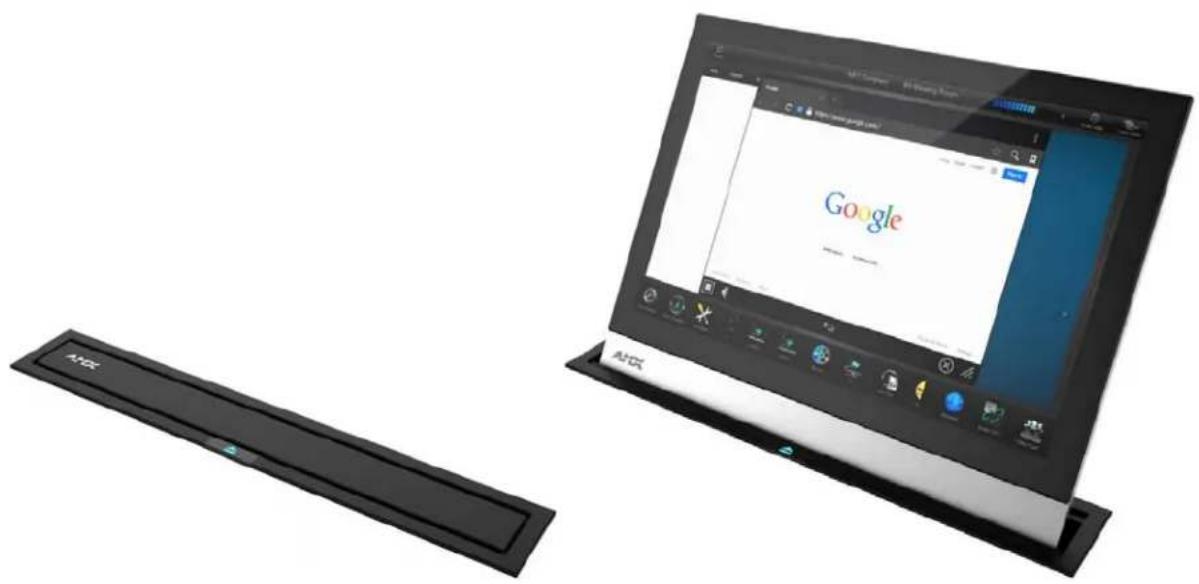
The MXR-1001 / 10.1" Modero X® Series G5 Retractable Touch Panel is a 10" Modero X G5 Touch Panel that can be mounted within the table so it hides away when not in use (FIG. 1). The motorized mount raises and retracts the panel with the press of a button or via NetLinx control.

FIG. 1 MXR-1001-BL (Lowered and Raised positions)
The Modero X Series G5 Retractable Touch Panels covered in this manual include:
| Modero X Series Retractable G5 Touch Panels | ||
| Name FG# Description | ||
| MXR-1001-BL FG5968-56 | 10.1" Modero X Series G5 Retractable Touch Panel - Black | |
| MXR-1001-SL FG5968-57 | 10.1" Modero X Series G5 Retractable Touch Panel - Silver | |
MXR-1001 Specifications
| MXR-1001 Specifications | |
| DIMENSIONS (HWD) 15 | 325" x 11.010" x 6.753" (389.25mm x 279.65mm x 171.53mm) |
| CUTOUT DIMENSIONS 1 | 0.701" x 1.984" (271.81mm x 50.39 mm) |
| WEIGHT 18.85 lbs (8.55 | Kg) |
| POWER CONSUMPTION | Full-On: 15.6W (In motion) / Full-On (no motion): 7.2W• S I e ep : 4 . 6 W• Shut Down 0.12• Start-Up Inrush Current: 7.1 amps |
| CERTIFICATIONS | • FCC Part 15 Class B • IC/CSA• C-Tick CISPR 22 Class B • I E C / EN - 6 0 95 0• CE EN 55022 Class B, EN 55024, and EN 55032 • UL 6 0 9 5 0- 1• RoHS/WEEE/ErP compliant |
| TOUCH SCREEN DISPLAY | • Display Type: TFT Active Matrix Color LCD with In-plane Switching Technology (IPS)• Display Size (WH): 9.9" x 6.7" (252mm x 170mm), 12.0" (304mm) diagonal• Viewable Area (WH): 8.5" x 5.3" (217mm x 136mm), 10.1" (257mm) diagonal• Resolution (WH): 1280x800• Aspect Ratio (WH): 16:9• Brightness: 400 cd/m2• Contrast Ratio: 700:1• Color Depth: 16.7M colors• Illumination: LED• Touch Overlay: Projected capacitive, multi-touch support, 3 simultaneous max |
| VIEWING ANGLE | • Vertical: ± 89°• Horizontal: ± 89° |
| EXTERNAL CONTROLS | Raise/Lower pushbutton with LED: Press to raise or lower the Touch PanelSleep Button: Press to activate sleep mode and powering off. Also provides access to setup pages for panel configuration. The Sleep button is located at the top center of the Touch Panel and can be disabled if desired.For information on configuring and programming X Series G5 touch panels, refer to the Modero X® Series G5 Touch Panels Configuration & Programming Manual. |
| MEMORY • SDRAM: 2 GB | Flash: 16 GBMaximum Project Size: 12 GB flash, available for apps and touch panel files |
| COMMUNICATIONS | Ethernet: 10/100 Auto MDI-X port, RJ-45 connector. Supported IP and IP-Based Protocols: UCP, TCP, ICMP, ICSP, IGMP, DHCP, SSH, FTP, DNS, RFB (for VNC), HTTPUSB: Two USB host 2.0, Type A ports that can be used for firmware upgrade, touch panel file transfer, document and image viewing, HID PeripheralsNear Field Communication (NFC): Supports standards ISO/IEC 15693, ISO/IEC 14443A, ISO/IEC 14443B; Unique Identifier (UID), typical range=.25", max = .5"Blueto th * :Mouse/Keyboard: HID Profile v1.1, requires MXA-BT Bluetooth Adapter (FG5968-19)Handset: Hands Free Profile v1.5, Headset Profile v1.2, requires MXA-BT Bluetooth Adapter (FG5968-19) and MXA-HST Bluetooth Handset (FG5968-17) |
| VIDEO • Supported Video | Codecs:MPEG2-TS: MPEG-2 Main Profile @High Level up to 720p at 25 fps (decode only)MPEG-2-TS: H.264 High Profile @Layer 4, AAC-LC up to 720p at 25 fps (encode/decode)MJPEG up to 720p at 25 fps (decode only)Supported Video Transport Streams: MPEG-TS for MPEG-2 and H.264, HTTP for MJPEGMax Number of Active Video Streams: 2 (720dpi/30fps)Video Conferencing: Panel-to-panel and video chat* |
| AUDIO • Microphone: -42 dB ±3 dB sensitivity FET microphoneSpeakers: 4 ohm, 2 Watt, 300 Hz cutoff frequencySupported Audio Codecs: MP2 Layer I and II, MP3 (8 kHz, 11.025 kHz, 12 kHz, 16 kHz, 22.05 kHz, 24 kHz, 32 kHz, 44.1 kHz, 48 kHz), AAC-LC (8 kHz, 96 kHz), G.711 with μLaw (VoIP* encode/decode at 8 kHz)Suggested max packet size for G.711 Voice: 20msFile Formats: WAV, MP3 (as part of touch panel file only - no USB storage)Intercom*: Full Duplex VoIP, SIP v2.0 | |
| GRAPHICS ENGINE | AMX G5: G5 enhanced feature set supporting multi-touch and gestures, scrolling, transitions, and applications. |
| EMBEDDED APPLICATIONS | Viewer Applications*: PDF, JPEG, BMP, PNG, TIFF, GIFRemote Management: VNC ServerVideo Conferencing: SkypeAudio Conferencing: Audio (Full Duplex Intercom*) |
| FRONT PANEL COMPONENTS | Light Sensor: Photosensitive light detector for automatic adjustment of the panel brightnessProximity Detector: Max range = ~3', typ range = ~1', FOV = ~10 degreesCamera: HD 720p camera for video conferencing/video chat support. The Camera LED indicates when the camera is active. |
| CONNECTIONS | Ethernet: 10/100 Auto MDI-X port, RJ-45 connector. Supported IP and IP-Based Protocols: UCP, TCP, ICMP, ICSP, IGMP, DHCP, SSH, FTP, DNS, RFB (for VNC), HTTPPower: 3-pin captive wire 24VUSB: Two USB host 2.0, Type A ports that can be used for firmware upgrade, touch panel file transfer, document and image viewing, HID Peripherals |
| ENVIRONMENTAL | Temperature (Operating): 32°F to 104°F (0°C to 40°C)Temperature (Storage): 4°F to 140°F (-20°C to 60°C)Humidity (Operating): 20% to 85% RHHumidity (Storage): 5% to 85% RHHat Dissipation: On: 53.2 BTU/hr, Standby: 24.6 BTU/hr |
| INCLUDED ACCESSORIES | PSR2.5 24VDC external power supply (FG423-47)Cardstock Installation Cutout Template11 Mounting Screws4 Mounting Clamps1 snap-on cable ferrite1 Mounting Spacer / 4 screws (60-5968-115MXA-USB-C, USB Port Cover Kit (FG5968-18)MXA-CLK, Modero X/S Series Cleaning Kit (FG5968-16) |
| OPTIONAL ACCESSORIES | MX-AC-TMPLT-MXR10, Aluminum Installation Router Guide (FG559-96)MXA-MP, Modero X/S Series Multi Preview (FG5968-20)MXA-MPL, Modero X/S Series Multi Preview Live (FG5968-10)MXA-BT Bluetooth USB Adapter for Modero X/S Series (FG5968-19)MXA-HST, Bluetooth Handset for Modero X/S Series Touch Panels (FG5968-17)NXA-ENET8-2POE, Gigabit PoE Ethernet Switch (FG2178-63) |
Touch Panel Aspect Ratio
While the touch panel screen physical dimensions fall between 16:9 and 16:10, any incoming video stream can be scaled to 16:9 if needed. This may lead to some letter boxing around the video in some cases.
Active Video Windows - Limitations
The term "Active Video Windows" refers to any "window" on the touch panel (which could be a Page, Popup, Sub-Page or Button) that is displaying active video content.
• Maximum supported number of active video windows displayed simultaneously on the panel: 2
While this limitation is not enforced (i.e the TPDesign5 application will allow you include any number of video windows in the panel design), attempting to display more than two active video windows at one time may have a negative impact on the panel's overall performance.
• Maximum supported resolution for video windows: 720dpi
• Maximum supported frame rate for video windows: 30fps
MXR-1001 Motor Controller
The MXR-1001 features the same hardware components and provides all of the functionality of the standard MXD-1001 10.1" Modero X G5 Touch Panel. The primary distinguishing feature of the MXR-1001 is the ability to raise and retract the touch panel. Therefore, there are electrical and firmware features specific to the MXR-1001 that provide control of the motorized mount. The MXR-1001 Motor Controller reports the physical state of the motor and panel to the NetLinx Master.
Powering On/Off the MXR-1001 Touch Panel
MXR-1001 touch panels may be powered on by touching the Sleep/Settings pushbutton (just like other G5 touch panels). The Sleep/Settings pushbutton is located in the center of the top panel of the touch panel (FIG. 2):
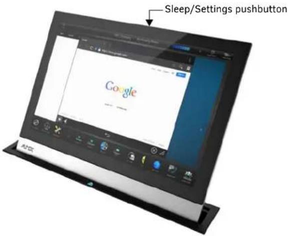
FIG. 2 MXR-1001-BL Sleep/Settings Pushbutton
The MXR-1001 also supports power-up via PoE signaling, but note that PoE is not a power supply option for the MXR-1001. To power off the panel, press and hold the button to invoke the on-screen menu, and select Power Off (FIG. 3):

FIG. 3 On-screen menu Power Off/Settings options
- If the device has gone into its Sleep mode, touching the touchscreen or pressing the Sleep button will reactivate it.
- Press and hold the Sleep button to access the Settings menu.
NOTE: Powering off the touch panel does not remove power to the motor. To completely remove power from the motor and touch panel, unplug the power cable (located on the Motor Mount).
Raising and Lowering the MXR-1001 Touch Panel
Press the external pushbutton (with LED) to raise and lower the touch panel on the MXR-1001.

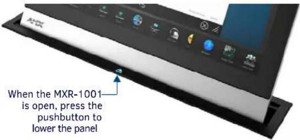
FIG. 4 Up/Down pushbutton
- If the panel is locked, the pushbutton is disabled until authentication credentials are provided (see Locking and Unlocking the MXR-1001 on page 10).
- The brightness of the pushbutton LED can be adjusted via the ^MCC Send Command (LEDBRIGHTNESS subcommand). The panel can be raised and lowered via the (MOTOR subcommand). Refer to the Modero X® Series G5 Touch Panels Configuration & Programming Manual for details
Warning Screen
When the touch panel is in motion (raising or lowering), a warning screen is displayed on the panel (FIG 5):
AMX
by HARMAN
Warning: Panel in motion. Keep clear of opening.
FIG. 5 MXR-1001 Warning: Panel In motion. Keep clear of opening.
NOTE: If the Up/Down pushbutton is pressed while the panel is in motion, the panel will reverse direction.
- Some touch panel components are automatically disabled when the panel is in the Lowered position - see the the Modero X® Series G5 Touch Panels - Configuration & Programming Manual for details.
- Application windows that are open when the panel is in motion are automatically closed. Popup windows will stay opened after the panel is completely raised and the warning message (FIG. 5) is closed.
- The pushbutton can be used to raise/lower the panel even if the MXR-1001 is not connected to a Master (for example during installation), as long as the MXR-1001 is powered.
Audio Alert
The Audio Alert feature allows the MXR-1001 to play a sound when the panel is raised, and/or a separate sound when the panel is lowered. The Panel Lower Sound and Panel Raise Sound settings can be configured under the "Sound" Settings menu. Note that by default, the Panel Raise sound is set to "None". Refer to the Modero X ® Series G5 Touch Panels Configuration & Programming Manual for details.
Locking and Unlocking the MXR-1001
The touch panel on the MXR-1001 can be locked and unlocked via the ^MCC Send Command (LOCK subcommand). By default, the panel is unlocked. When the panel is locked, the Pushbutton (see FIG. 4 on page 10) is disabled.
- When the MXR-1001 is unlocked, press the pushbutton to raise or lower the panel.
- When the MXR-1001 is locked, the pushbutton is disabled until authentication credentials are verified. When locked, button presses are sent to the Master for potential action via NetLinx code. If the panel drops offline while locked, the panel can only be raised or lowered via the Motor SSH command. Note that if High Security Mode is enabled, SSH functionality will not be available. Refer to the Modero X® Series G5 Touch Panels - Configuration & Programming Manual for details.
Configuration and Programming
MXR-1001 touch panels are equipped with a Settings menu that provides the ability to configure various features on the panels. To access the Settings menu, press and hold the Sleep button, and select Settings (FIG. 3). This opens the main Settings menu (FIG. 6):

FIG. 6 Main Settings menu
NOTE: The MXR-1001 Settings menu is similar to the Settings menu on other X Series G5 touch panels. The main difference is the addition of the "Panel Raise Sound Select" and "Panel Lower Sound Select" options in the Sound page. Refer to the Modero X® Series G5 Touch Panels Configuration & Programming Manual for details.
MXR-1001 Send Commands
There are two new G5 Send Commands that are specific to the MXR-1001:
- "^MCC-
-"?POS-
This event is sent either in reply to the “?POS” query, or unsolicited to report a status change. It is also sent when the panel first comes online to report initial status.
Refer to the Modero X® Series G5 Touch Panels Configuration & Programming Manual for details on using these commands, as well as all standard G5 Send Commands.
NOTE: Note: Programming the Modero X Series G5 touch panels require the use of the latest versions of NetLinx Studio and TPDesign5, both are available to download at www.amx.com.
Cleaning the Touch Overlay and Case
The MXR-1001 comes with the MXA-CLK Modero X Series Cleaning Kit (FG5968-16), which may be used to clean fingerprints and dirt from the device. This kit comes with cleaning cloths and a bottle of cleaning fluid specifically for use with the device.
- When cleaning the device, do not directly spray the device with cleaning fluid. Instead, spray the cloth and then apply the cloth to the touch screen.
- Do NOT use abrasives of any type to clean the device, as abrasives may permanently damage or remove the device's finish
Additional Documentation
Refer to the Modero X Series G5 Touch Panels Configuration and Programming Manual for details on configuring and programming G5 touch panels, including:
• Information on Modero X Series G5 Programming, including Transitioning from G4 to G5
- Detailed descriptions of each page and page option available in the G5 Settings Menu
- Firmware upgrades via the G5 Settings Menu (Reset and Update page)
• Using Content Sharing
- Using Gestures
• MXA-MP and MXA-MPL Programming
• Detailed descriptions of all G5-supported Send Commands and SSH Commands
NOTE: Refer to the Modero G5 Configuration and Programming - X Series G5 Touch Panels Instruction Manual for details.
NOTE: Touch Panel files for G5 Touch Panels are created via TPDesign5 software (available to download from www.amx.com). Refer to the TPDesign5 online help and Instruction Manual for details.
Installing the MXR-1001
Overview
Read these instructions in their entirety before beginning the installation. The installation requires specific steps to be performed the specified order.
CAUTION: This installation requires specific woodworking skills. Only a professional, AMX-qualified installer should perform this installation. Installation must conform to all local codes. This product may not be installed by the end-user.
NOTE: Due to the weight of the MXR-1001, this installation requires TWO INSTALLERS.
Required Accessories (Not Included)
- Straight-Cut Router bit: Freud 12-128 or Whiteside 1072 (0.5" or 12mm / 12.7mm OD)
• Guide Bushing: Woodcraft 144693 (.75" or 19 mm OD)
• Bushing Lock Nut: Woodcraft 144696
1) Unbox the MXR-1001 and Remove Shipping Screws
- Carefully remove the MXR-1001 from the shipping box and remove packing materials. Note that the MXR-1001 ships with two Shipping Screws installed on the bottom surface of the Motor (FIG. 7):
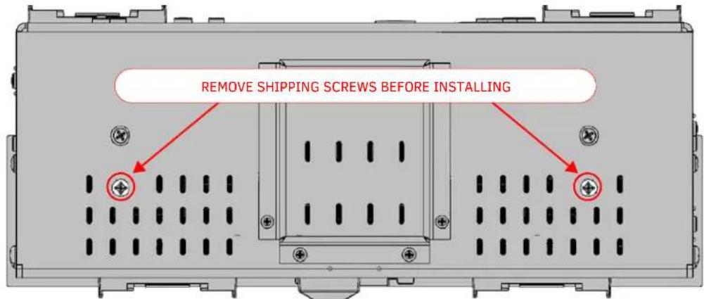
FIG. 7 MXR-1001 BOTTOM View - remove shipping screws before installation
- Remove the Shipping Screws before installing the MXR-1001.
2) Select a Suitable Location
Ensure that the MXR-1001 will not interfere with the normal use of the work space when installed, both above and below the mounting surface. For example, ensure that the Motor chassis does not interfere with the user's legs when seated at the table. Also, ensure that other devices installed in proximity to the MXR-1001 will not interfere with the installation and use of the MXR-1001.
Mounting Surface Requirements
| Above Mounting Surface (HWD): 9.57" x 1 | 0.55" x 4.53" (243mm x 268mm x 115mm) |
| Below Mounting Surface (HWD): | 15.37" x 12.04" x 6.78" (391mm x 306mm x 173mm) |
| Mounting Surface Thickness: Min: 0.5" (12.7mm) / Max: 2.0" (50mm) | |
NOTE: Use the included surface extender for surfaces thicker than 2" (50mm). Refer to the MXR-1001 Hardware Installation Guide for details.
Above-Surface Dimensions
FIG. 8 indicates the above-surface dimensions of the MXR-1001, including the Bezel:
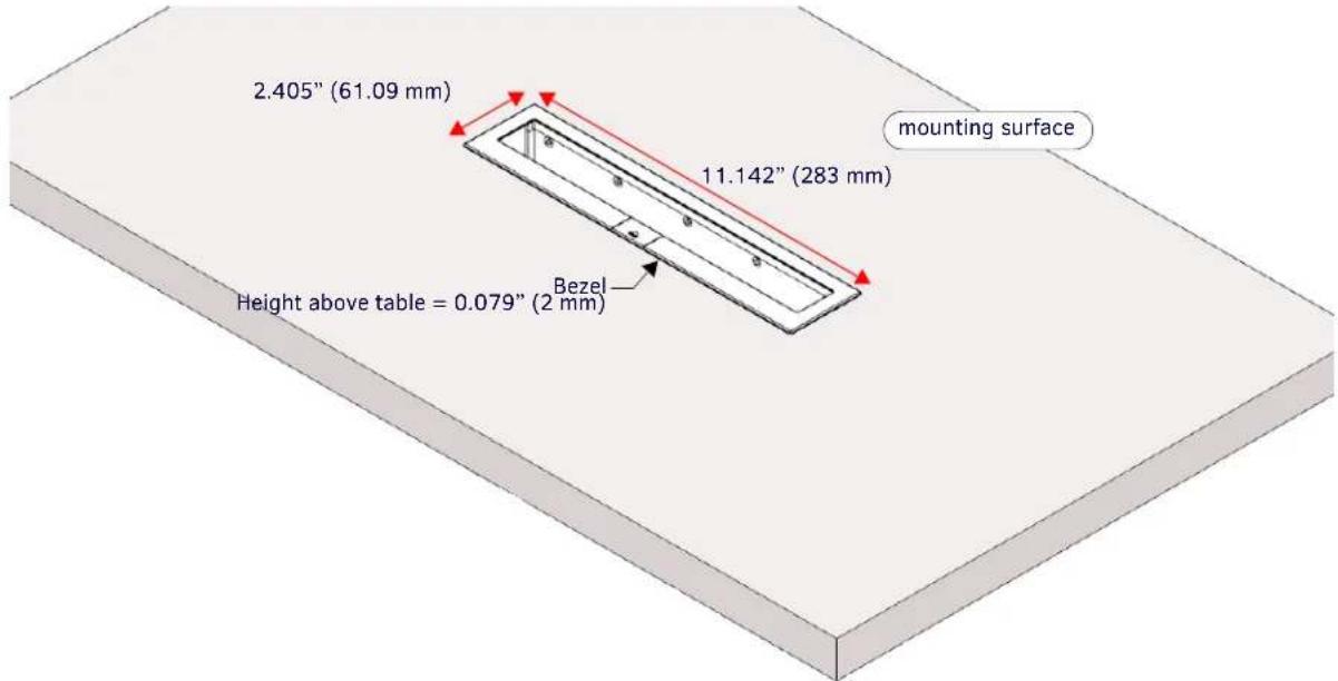
FIG. 8 Above-Surface Dimensions of MXR-1001
Below-Surface Dimensions
FIG. 9 provides a top view of an installed MXR-1001, to indicate the area required below the mounting surface for the chassis and Mounting Clamps:
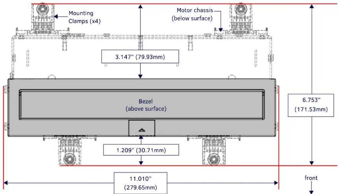
FIG. 9 MXR-1001: Top view, Indicating area required below the mounting surface
FIG. 10 indicates the below-surface depth requirements for the MXR-1001 (side view):

FIG. 10 Dimensions of the MXR-1001 (side view, below the mounting surface)
Hole Cutout Dimensions for the Mounting Surface
Refer to the following table for the dimensions of the actual hole cut out in the mounting surface, resulting from using the Router Guide and required accessories:

FIG. 11 Above-Surface Dimensions of MXR-1001
3) Cut the Hole In the Mounting Surface
CAUTION: Always wear safety glasses when operating the router. Failure to comply may result in eye injury.
Using the specified guide bushing and router bit (not included, see Required Accessories):
- Use the appropriate Installation Router Guide to mark the edges of the cutout.
-
Carefully cut the opening in the table surface with the router.
-
Little clearance exists between the MXR-1001 and the hole cutout in the mounting surface. Once the MXR-1001 assembly has been installed, the Bezel will cover the cutout hole.
- Carefully align the cutout with the edges or other appropriate features in the table or mounting surface. If the cutout is misaligned, the installed unit will be misaligned.
- Use a drill and drill bit to make a starting hole within the boundary of the cutout. Use an appropriate cutting tool to finish the cutout.
- Verify that the cutting tool will not tear or chip the top surface. Ensure that the top surface of the mounting surface is not damaged beyond the width of the trim bezel as the cutout is made.
NOTE: The process of making the cutout will create substantial dust - prepare the environment appropriately.
- File the four corners of the routing area square after routing.
4) Install the MXR-1001 Into the Mounting Surface
- Before the MXR-1001 can be installed, the Bezel must be separated from the Motor chassis: Remove the 11 screws (3 on the front, 4 on the back, and 2 on each side), unplug the MXR cable, and lift the Bezel off of the Motor chassis (FIG. 14):
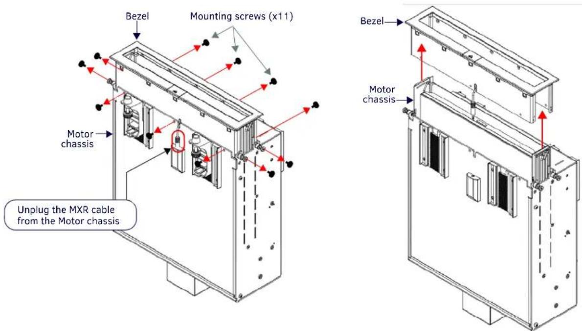
FIG. 12 Attaching the Bezel to the Motor chassis
- Position the Motor chassis directly beneath the cutout hole. Verify that it is oriented correctly: the plug for the MXR cable is located on the front of the chassis (USB, Ethernet and Power connectors are on the rear).
NOTE: The Motor chassis weights approximately 18lbs (8.16Kg) - it will require a second pair of hands to keep it positioned precisely beneath the cutout hole. Additionally, consider using the packaging material from the MXR-1001 shipping box as a support to keep it in place during installation.

FIG. 13 Positioning the Motor beneath the Cutout
- Carefully lift the Motor chassis up so that the top of the chassis fits into the cutout and is flush with the top of the mounting surface.
- Position the Bezel directly above the cutout hole. Verify that the Bezel is oriented correctly relative to the Motor chassis - the pushbutton is located on the front of the Bezel.
- Route the MXR cable from the Bezel through the slot on the front center of the Bezel, and run it through the cutout hole.
- Lower the Bezel through the cutout hole and slide it onto the top of the Motor chassis.
- Secure the Bezel to the Motor chassis using all 11 supplied mounting screws - there are 3 mounting holes on the front, 4 on the back, and 2 on each side (FIG. 14):


FIG. 14 Attaching the Bezel to the Motor Chassis
NOTE: In some cases, one or more of the mounting holes on the Bezel/Motor chassis assembly may be obstructed and impossible to access for installing Mounting Screws. The MXR-1001 can be installed securely without using all 11 mounting screws. Always use as many of the Mounting Screws as possible and verify that the Bezel is secured to the Motor chassis.
8. Plug the MXR Cable from the Bezel into the connector on the front panel of the Motor chassis (beneath the mounting surface - see FIG. 12).
9. With the Motor & Bezel assembly positioned in the mounting surface, use the 2 included Mounting Clamps to secure the assembled unit to the mounting surface. The Mounting Clamps slide into the two matching (ratcheted) Clamp Slots on each side of the Motor chassis. To install the Mounting Clamps on the sides of the Motor chassis:

FIG. 15 Clamp Slots and Side Clamp (X4)
a. Insert each Mounting Clamp into a ratcheted Clamp Slot from the bottom, and slide each clamp up as far as possible, until the rubber foot on each Clamp contacts the underside of the mounting surface (see FIG. 15).
b. Tighten the thumb screws on all Mounting Clamps to secure the MXR-1001 to the surface (FIG. 16):

FIG. 16 MXR-1001 - Installed (side view)
5) Connect Ethernet, USB and Power Cables
Once the MXR-1001 is installed, plug in the Power, Ethernet and (optionally) USB cable(s). These connectors are all located on the rear panel of the Motor chassis.
- Power (3-Pin Captive Wire): Connect to the included PSR2.5 24VDC external power supply. For pinout information on this connector, refer to the MXR-1001 Hardware Installation Guide.
- Ethernet (RJ45): Use a CAT5 Ethernet cable to connect the MXR-1001 to a Gigabit Ethernet Switch. For information on pinouts, signals, and LED blink patterns for this connector, refer to the MXR-1001 Hardware Installation Guide.
NOTE: Clip the included snap-on cable Ferrite onto the Ethernet cable as close as possible to the Ethernet (RJ45) connector on the rear panel.
- USB (Type A, x2): For firmware upgrades, touch panel file transfers, JPEG image viewer, and HID Peripherals.
NOTE: If the MXR-1001 is not connected to a Master, the physical pushbutton can still be used to raise/lower the panel.
Appendix A: Waking the Panel via PoE
Overview
This section describes a power saving feature designed into the non-POE versions of the ModeroX G5 line of touch panels, including the MXD/T-1901 and MXD/T-2001 Surface/Wall Mount touch panels, as well as MXR-1001 10.1" Retractable Touch Panels.
Traditionally, in order to wake a panel from shutdown, the user would need to press the user button, which meant they had to be physically located at the panel. This feature would allow one to remotely cycle POE power to the panel's Ethernet port in order to wake it. Since the panels have always had a way to remotely shut them down, this new feature now allows a remote start up. Power management could be programmed into the master to, for example, shutdown the panels at the end of the day, and then wake them up again the next morning without human intervention.
Detail Description
ModeroX G5 panels feature a hardware design that will recognize POE power and wake a panel from shutdown.
NOTE: Since these panels do not actually use POE power, it is recommended that if attached to a POE port, the port is configured to normally disable POE power.
When it comes time to wake the panel, the POE switched is accessed and POE power to the port is turned on just long enough to wake the panel, and then turned off. Depending on the switch, the cycle time could be as little as three or four seconds. A test should be conducted to determine the minimum dwell time to leave POE power enabled in order to reliably wake the panel.
10" Retractable Panel Limitations
The 10" retractable panel has the wake up circuit on both the spare and signal pairs. Additionally, it also includes a load resistor that will draw enough power on the POE in order to prevent POE cycling. As a consequence, if POE power were to be kept enabled while the panel was running or shutdown, the POE port could draw up to 1 watt of power continually.
It is for this reason that it is it is recommended to have power disabled normally, but then turn it on for only a few seconds in order to wake the panel.
Noteworthy POE Switch Interactions
In one installation, panels were installed on POE switches with the POE power enabled for their ports, which resulted in cycling due to insufficient POE load. This particular switch would not route packets to a port which was a recognized POE device but which had no power applied. As a consequence, when power would cycle on, packets were routed to the port, but then when the POE power was removed due to insufficient POE load, packet would no longer be routed to that port.
The result would be that the panel would continually drop off line and then back on line as the POE power cycled. After recommending that the POE power be disabled to the port feeding the panel, the problem went away.
Appendix B: Troubleshooting
Overview
This section describes the solutions to possible hardware/firmware issues that could arise during the common operation of a Modero X Series G5 touch panel.
In Case of a Power Failure (Manually Raising / Lowering the Touch Panel)
In the case of a power failure, it may be necessary to raise or lower the MXR-1001 touch panel manually. The MXR-1001 is equipped with a Lead Screw that provides a manual override mechanism for raising or lowering the touch panel without using the motor. The Lead Screw is located on the bottom of the Motor Mount (under a protective metal shroud), as shown in FIG. 17:

FIG. 17 Manual Motor Override
- To access the lead screw, remove the metal shroud from the bottom of the Motor Mount (secured by six mounting screws).
- Unplug the four-wire connector.
-
Use a flat-head screwdriver to turn the lead screw and raise or lower the panel:
-
To manually lower the touch panel, turn the lead screw clockwise until it is fully lowered.
- To manually raise the touch panel, turn the lead screw counter-clockwise until it is fully raised.
NOTE: If power is lost and restored while the panel is in its deployed (fully raised) position, the panel will remain raised. If power is lost and restored while the panel is in its closed (fully lowered) position, the panel will remain closed. If power is lost and restored while the touch panel is neither fully raised or fully lowered (closed), the motor will automatically retract the panel to its closed position.
Panel Doesn't Respond To Touches
Symptom: The device either does not respond to touches on the touch screen or does not register the touch as being in the correct area of the screen.
If the screen is off:
- The device may be in Display Sleep Mode. Press and hold the Sleep button to wake up the panel.
- The device may not be connected to power. Verify that the power source is connected to the device and receiving power.
Panel Isn't Appearing In The Online Tree Tab
- Verify that the System number is the same on both the NetLinx Studio Project Navigator window and the System Settings page on the device.
- Verify the proper NetLinx Master IP and connection methods entered into the Master Connection section of the System Settings page.
Can't Connect To a NetLinx Master
Symptom: I can't seem to connect to a NetLinx Master using NetLinx Studio.
Select Settings > Master Comm Settings > Communication Settings > Settings (for TCP/IP), and uncheck the "Automatically Ping the Master Controller to ensure availability".
The pinging is to determine if the Master is available and to reply with a connection failure instantly if it is not. Without using the ping feature, a connection may still be attempted, but a failure will take longer to be recognized.
NOTE: If you are trying to connect to a Master controller that is behind a firewall, you may have to uncheck this option. Most firewalls will not allow ping requests to pass through for security reasons.
When connecting to a NetLinx Master controller via TCP/IP, the program will first try to ping the controller before attempting a connection. Pinging a device is relatively fast and will determine if the device is off-line, or if the TCP/IP address that was entered was incorrect.
If you decide not to ping for availability and the controller is off-line, or you have an incorrect TCP/IP address, the program will try for 30-45 seconds to establish a connection.
Only One Modero Panel In My System Shows Up
Symptom: I have more than one Modero panel connected to my System Master and only one shows up.
Multiple NetLinx Compatible devices can be associated for use with a single Master. If the user does not assign a device number, one will be assigned automatically to the panel. When using multiple panels, different Device Number values have to be assigned to each panel.
- Press and hold the Sleep button to open the Settings menu.
- Select the NetLinx menu, enter 1988 into the on-screen Keypad's password field, and press Done when finished.
- Enter a Device Number value for the panel into the Device Number Keypad. The range is from 1 - 32000.


- IMPORTANT SAFETY INSTRUCTIONS
- COPYRIGHT NOTICE
- LIABILITY NOTICE
- AMX WARRANTY AND RETURN POLICY
- ESD WARNING
- FCC AND CANADA EMC COMPLIANCE INFORMATION
- WIRELESS TRANSMITTER COMPLIANCE INFORMATION
- WEEE NOTICE
- CHINA COMPLIANCE INFORMATION
- TABLE OF CONTENTS
- MXR-1001 7
- INSTALLING THE MXR-1001 12
- APPENDIX A: WAKING THE PANEL VIA POE 19
- APPENDIX B: TROUBLESHOOTING ....20
- MXR-1001
- OVERVIEW
- MXR-1001 SPECIFICATIONS
- TOUCH PANEL ASPECT RATIO
- ACTIVE VIDEO WINDOWS - LIMITATIONS
- MXR-1001 MOTOR CONTROLLER
- POWERING ON/OFF THE MXR-1001 TOUCH PANEL
- RAISING AND LOWERING THE MXR-1001 TOUCH PANEL
- WARNING SCREEN
- AUDIO ALERT
- LOCKING AND UNLOCKING THE MXR-1001
- CONFIGURATION AND PROGRAMMING
- MXR-1001 SEND COMMANDS
- CLEANING THE TOUCH OVERLAY AND CASE
- ADDITIONAL DOCUMENTATION
- INSTALLING THE MXR-1001
- REQUIRED ACCESSORIES (NOT INCLUDED)
- UNBOX THE MXR-1001 AND REMOVE SHIPPING SCREWS
- SELECT A SUITABLE LOCATION
- ABOVE-SURFACE DIMENSIONS
- BELOW-SURFACE DIMENSIONS
- HOLE CUTOUT DIMENSIONS FOR THE MOUNTING SURFACE
- CUT THE HOLE IN THE MOUNTING SURFACE
- INSTALL THE MXR-1001 INTO THE MOUNTING SURFACE
- CONNECT ETHERNET, USB AND POWER CABLES
- APPENDIX A: WAKING THE PANEL VIA POE
- DETAIL DESCRIPTION
- 10" RETRACTABLE PANEL LIMITATIONS
- NOTEWORTHY POE SWITCH INTERACTIONS
- APPENDIX B: TROUBLESHOOTING
- IN CASE OF A POWER FAILURE (MANUALLY RAISING / LOWERING THE TOUCH PANEL)
- PANEL DOESN'T RESPOND TO TOUCHES
- PANEL ISN'T APPEARING IN THE ONLINE TREE TAB
- CAN'T CONNECT TO A NETLINX MASTER
- ONLY ONE MODERO PANEL IN MY SYSTEM SHOWS UP
Brand : AMX
Model : MXR-10010-SL
Category : Touchscreen