
HPX-MSP-7-SL - Touchscreen AMX - Free user manual and instructions
Find the device manual for free HPX-MSP-7-SL AMX in PDF.


| Product Type | HydraPort Touch Connection Port with 7" Panel |
| Model | HPX-MSP-7-SL (Silver) |
| Dimensions (H x W x D) | 4.567" x 10.571" x 6.526" (116 mm x 268.51 mm x 165.75 mm) |
| Cutout Dimensions (Width x Length) | 8.358" x 5.915" (212.30 mm x 150.25 mm) |
| Weight | 3.58 lbs (1.62 kg) |
| Power Consumption | Full On: 13W, Typical: 7W, Standby: 4.5W, Shutdown: 0.7W |
| Power Supply | PoE (802.3af, class 0); requires external PoE injector or switch (not included) |
| Display Type | 7" TFT Active Matrix Color LCD with FFS technology |
| Display Resolution | 1024 x 600 (landscape) |
| Brightness | 400 cd/m² |
| Color Depth | 16.7M colors |
| Touch Overlay | Resistive |
| Ethernet | 10/100 Auto MDI-X, RJ-45 |
| USB | 1 x USB Host 2.0, Type A |
| Bluetooth | Supported via optional MXA-BT adapter (HID v1.1) |
| Video Decode | MPEG2, H.264, MJPEG up to 720p @ 25 fps |
| Audio | Built-in microphone and 1.5W speaker; full-duplex VoIP (SIP v2.0) |
| Operating Temperature | 32°F to 104°F (0°C to 40°C) |
| Storage Temperature | 4°F to 140°F (-20°C to 60°C) |
| Humidity (Operating) | 20% to 85% RH |
| Included Accessories | Cardstock cutout template, 4 side clamps |
| Certifications | FCC Part 15 Class B, RoHS/WEEE compliant |
| Cleaning Instructions | Clean only with dry cloth; do not use water or liquids |
| Safety Warnings | Do not open; no user-serviceable parts; refer servicing to qualified personnel |
| Mounting Surface Thickness | 0.5" to 2.0" (12.7 mm to 50 mm) |
Frequently Asked Questions - HPX-MSP-7-SL AMX
User questions about HPX-MSP-7-SL AMX
0 question about this device. Answer the ones you know or ask your own.
Ask a new question about this device
Download the instructions for your Touchscreen in PDF format for free! Find your manual HPX-MSP-7-SL - AMX and take your electronic device back in hand. On this page are published all the documents necessary for the use of your device. HPX-MSP-7-SL by AMX.
USER MANUAL HPX-MSP-7-SL AMX
INSTALLATION & HARDWARE REFERENCE MANUAL
HYDRAPORT TOUCH CONNECTION PORTS
HPX-MSP-7-SL 8 MODULE CONNECTION PORT WITH 7" PANEL (SILVER)
HPX-MSP-7-BL 8 MODULE CONNECTION PORT WITH 7" PANEL (BLACK)
HPX-MSP-10-SL 10 MODULE CONNECTION PORT WITH 10.1" PANEL (SILVER)
HPX-MSP-10-BL 10 MODULE CONNECTION PORT WITH 10.1" PANEL (BLACK)

natural_image
Two black laptops with digital interface displays, one open and one closed, both showing navigation controls (no visible text or symbols on screens)IMPORTANT SAFETY INSTRUCTIONS
-
READ these instructions.
-
KEEP these instructions.
-
HEED all warnings.
-
FOLLOW all instructions.
-
DO NOT use this apparatus near water.
-
CLEAN ONLY with dry cloth.
-
DO NOT block any ventilation openings. Install in accordance with the manufacturer's instructions.
-
DO NOT install near any heat sources such as radiators, heat registers, stoves, or other apparatus (including amplifiers) that produce heat.
-
DO NOT defeat the safety purpose of the polarized or grounding type plug. A polarized plug has two blades with one wider than the other. A grounding type plug has two blades and a third grounding prong. The wider blade or the third prong are provided for your safety. If the provided plug does not fit into your outlet, consult an electrician for replacement of the obsolete outlet.
-
PROTECT the power cord from being walked on or pinched, particularly at plugs, convenience receptacles, and the point where they exit from the apparatus.
-
ONLY USE attachments/accessories specified by the manufacturer.

-
USE ONLY with a cart, stand, tripod, bracket, or table specified by the manufacturer, or sold with the apparatus. When a cart is used, use caution when moving the cart/apparatus combination to avoid injury from tip-over.
-
UNPLUG this apparatus during lightning storms or when unused for long periods of time.
-
REFER all servicing to qualified service personnel. Servicing is required when the apparatus has been damaged in any way, such as power-supply cord or plug is damaged, liquid has been spilled or objects have fallen into the apparatus, the apparatus has been exposed to rain or moisture, does not operate normally, or has been dropped.
-
DO NOT expose this apparatus to dripping or splashing and ensure that no objects filled with liquids, such as vases, are placed on the apparatus.
-
To completely disconnect this apparatus from the AC Mains, disconnect the power supply cord plug from the AC receptacle.
-
Where the mains plug or an appliance coupler is used as the disconnect device, the disconnect device shall remain readily operable.
-
DO NOT overload wall outlets or extension cords beyond their rated capacity as this can cause electric shock or fire.

The exclamation point, within an equilateral triangle, is intended to alert the user to the presence of important operating and maintenance (servicing) instructions in the literature accompanying the product.

The lightning flash with arrowhead symbol within an equilateral triangle is intended to alert the user to the presence of uninsulated "dangerous voltage" within the product's enclosure that may be of sufficient magnitude to constitute a risk of electrical shock to persons.

ESD Warning: The icon to the left indicates text regarding potential danger associated with the discharge of static electricity from an outside source (such as human hands) into an integrated circuit, often resulting in damage to the circuit.
WARNING: To reduce the risk of fire or electrical shock, do not expose this apparatus to rain or moisture.
WARNING: No naked flame sources - such as lighted candles - should be placed on the product.
WARNING: Equipment shall be connected to a MAINS socket outlet with a protective earthing connection.
CAUTION: To reduce the risk of electric shock, grounding of the center pin of this plug must be maintained.
COPYRIGHT NOTICE
AMX© 2016, all rights reserved. No part of this publication may be reproduced, stored in a retrieval system, or transmitted, in any form or by any means, electronic, mechanical, photocopying, recording, or otherwise, without the prior written permission of AMX. Copyright protection claimed extends to AMX hardware and software and includes all forms and matters copyrightable material and information now allowed by statutory or judicial law or herein after granted, including without limitation, material generated from the software programs which are displayed on the screen such as icons, screen display looks, etc. Reproduction or disassembly of embodied computer programs or algorithms is expressly prohibited.
LIABILITY NOTICE
No patent liability is assumed with respect to the use of information contained herein. While every precaution has been taken in the preparation of this publication, AMX assumes no responsibility for error or omissions. No liability is assumed for damages resulting from the use of the information contained herein. Further, this publication and features described herein are subject to change without notice.
AMX WARRANTY AND RETURN POLICY
The AMX Warranty and Return Policy and related documents can be viewed/downloaded at www.amx.com.
ESD WARNING
 | To avoid ESD (Electrostatic Discharge) damage to sensitive components, make sure you are properly grounded before touching any internal materials.When working with any equipment manufactured with electronic devices, proper ESD grounding procedures must be followed to make sure people, products, and tools are as free of static charges as possible. Grounding straps, conductive smocks, and conductive work mats are specifically designed for this purpose.Anyone performing field maintenance on AMX equipment should use an appropriate ESD field service kit complete with at least a dissipative work mat with a ground cord and a UL listed adjustable wrist strap with another ground cord |


WARNING: Do Not Open! Risk of Electrical Shock. Voltages in this equipment are hazardous to life. No user-serviceable parts inside. Refer all servicing to qualified service personnel.
Place the equipment near a main power supply outlet and make sure that you can easily access the power breaker switch.
WARNING: This product is intended to be operated ONLY from the voltages listed on the back panel or the recommended, or included, power supply of the product. Operation from other voltages other than those indicated may cause irreversible damage to the product and void the products warranty. The use of AC Plug Adapters is cautioned because it can allow the product to be plugged into voltages in which the product was not designed to operate. If the product is equipped with a detachable power cord, use only the type provided with your product or by your local distributor and/or retailer. If you are unsure of the correct operational voltage, please contact your local distributor and/or retailer.
FCC AND CANADA EMC COMPLIANCE INFORMATION:
This device complies with part 15 of the FCC Rules. Operation is subject to the following two conditions:
(1) This device may not cause harmful interference, and (2) this device must accept any interference received, including interference that may cause undesired operation.
NOTE: This equipment has been tested and found to comply with the limits for a Class B digital device, pursuant to part 15 of the FCC Rules. These limits are designed to provide reasonable protection against harmful interference in a residential installation. This equipment generates, uses and can radiate radio frequency energy and, if not installed and used in accordance with the instructions, may cause harmful interference to radio communications. However, there is no guarantee that interference will not occur in a particular installation. If this equipment does cause harmful interference to radio or television reception, which can be determined by turning the equipment off and on, the user is encouraged to try to correct the interference by one or more of the following measures:
•Reorient or relocate the receiving antenna.
- Increase the separation between the equipment and receiver.
- Connect the equipment into an outlet on a circuit different from that to which the receiver is connected.
- Consult the dealer or an experienced radio/TV technician for help.
Approved under the verification provision of FCC Part 15 as a Class B Digital Device.
Caution: Changes or modifications not expressly approved by the manufacturer could void the user's authority to operate this device.
CAN ICES-3 (B)/NMB-3(B)
EU COMPLIANCE INFORMATION:
Eligible to bear the CE mark; Conforms to European Union Low Voltage Directive 2014/35/EU; European Union EMC Directive 2014/30/EU; European Union Restriction of Hazardous Substances Recast (RoHS2) Directive 2011/65/EU; European Union WEEE (recast) Directive 2012/19/EU; European Union Eco-Design Directive 2009/125/EC; European Union Registration, Evaluation, Authorization and Restriction of Chemicals (REACH) Directive 1907/2006.
This product contains batteries that are covered under the 2006/66/EC European Directive, which cannot be disposed of with normal household waste. Please follow local regulations.
You may obtain a free copy of the Declaration of Conformity by visiting http://www.amx.com/techcenter/certifications.asp.
WEEE NOTICE:
 | This appliance is labeled in accordance with European Directive 2012/19/EU concerning waste of electrical and electronic equipment (WEEE). This label indicates that this product should not be disposed of with household waste. It should be deposited at an appropriate facility to enable recovery and recycling. |
CHINA COMPLIANCE INFORMATION:
 | This device is designed and evaluated under the condition of non-tropical climate; it can only be used in locations in non-tropical climate areas. Using the device in tropical climate areas could result in a potential safety hazard.该设备的设计和测试是在非热带气候条件进行的,它只适用在非热带气候的地区,在热带气候地区使用可能会导致潜在的安全隐患。 |
 | This device is designed and evaluated under the condition of altitude below 2000 meters above sea level; it can only be used in locations below 2000 meters above sea level. Using the device above 2000 meters could result in a potential safety hazard.该设备的设计和测试是在海拔2000米高度以下进行的,它只适用在海拔2000米以下的地区,在海拔2000米以上使用可能会导致潜在的安全隐患 |
Table of Contents
HPX-MSP-7/10 HydraPort Touch Connection Ports 6
Overview 6
HPX-MSP-7 7
Overview 7
HPX-MSP-7 Specifications 7
HPX-MSP-10 9
Overview 9
HPX-MSP-10 Specifications 9
Installing HPX Flip-Up Panels 11
Overview 11
1) Insert Additional HydraPort Connectivity Modules.... 11
2) Select a Suitable Location.... 14
Location Notes 14
Mounting Surface Requirements 14
HPX-MSP-7 Dimensions and Space Requirements 14
HPX-MSP-10 Dimensions and Space Requirements 15
3) Cut the Hole In the Mounting Surface 15
4) Install the HPX-MSP-7/10 Into the Mounting Surface.... 16
5) Connect Ethernet and USB Cables.... 17
Secure Cables Beneath the Mounting Surface.... 18
Troubleshooting 19
Overview 19
Removing the Touch Panel Assembly 19
1) Power Off the Panel and Disconnect Cables 19
2) Remove the Touch Panel Assembly From the HPX Base Assembly 19
Adjusting the Flip-Up Movement for the Panel 20
1) Remove the Touch Panel Assembly from the HPX Base Assembly.... 20
2) Adjust the Lid Movement Adjust Screws.... 20
Increasing Flip-Up Panel Motion Resistance 20
Decreasing Flip-Up Panel Motion Resistance.... 20
3) Replace the Touch Panel Assembly into the HPX Base Assembly 20
HPX-MSP-7/10 HydraPort Touch Connection Ports
Overview
This document provides installation instructions for the HPX-MSP-7 (8 Module Connection Port with 7" Panel) and HPX-MSP-10 (10 Module Connection Port with 10.1" Panel).
For configuration and programming information, refer to the HydraPort Touch Connection Ports Configuration and Programming Manual.
For information on designing touch panel pages intended to optimize the HPX-MSP experience, please refer to the TPDesign4 Operation Reference Guide and the User Interface Design Guide, both available at www.amx.com. The HPX-MSP-7/10 touch panels covered in this document are listed in the following table:
| HPX-MSP-7/10 Touch Panels | |||
| FG# Product Name Description Color | |||
| FG571-07 | HPX-MSP-7-BL | 8 Module Touch Connection Port with 7" Panel, | Black |
| FG571-08 | HPX-MSP-7-SL | 8 Module Touch Connection Port with 7" Panel | Silver |
| FG571-09 HPX-MSP-10-SL 10 Module Touch Connection Port with 10.1" Panel Silver | |||
| FG571-10 HPX-MSP-10-BL 10 Module Touch Connection Port with 10.1" Panel Black | |||

FIG. 1 HPX-MSP-7 and HPX-MSP-10
HPX-MSP-7
Overview
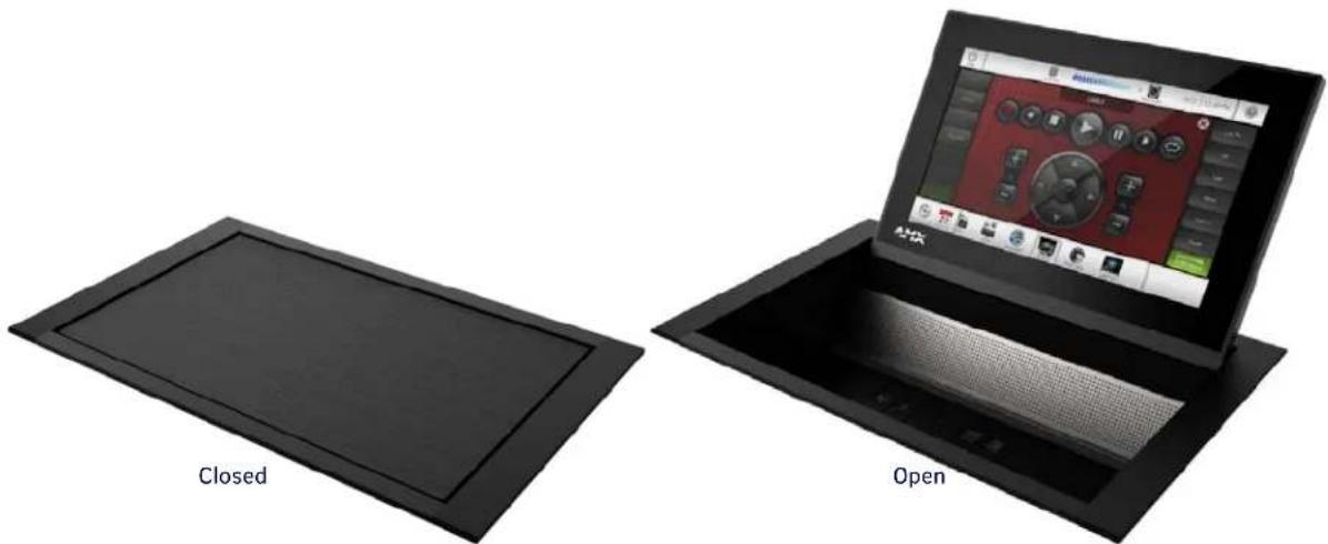
The HPX-MSP-7 / HydraPort Touch Connection Port with 7" Panel is an 8 Module HydraPort Connection Port with a 7" Modero S Series Touch Panel built into the cover. By combining device connectivity and room control into a single unit, the HPX-MSP-7 reduces clutter and saves space on the table top. Thanks to an elegant yet practical design, HPX-MSP-7 looks great in any room, from huddle spaces to large conference rooms. When closed, the unit sits flush with the table top to keep the meeting space neat and clean. When open, the unit provides easy access to the HydraPort modules and a full-featured Modero S Series Touch Panel. The HPX-MSP-7 includes a specially designed, ultra-thin 7" control panel that includes all the great Modero S features, including a brilliant 24-color depth, PoE connectivity, video streaming, and VoIP support – all at an economical price point.
natural_image
Two black electronic devices: a closed panel and an open screen with a red control interface (no text or symbols visible on the devices themselves)FIG. 2 HPX-MSP-7 (Open & Closed positions)
HPX-MSP-7 Specifications
| HPX-MSP-7 Specifications | |
| MODELS AVAILABLE: • HPX-MSP-7-SL, Silver: FG571-08• HPX-MSP-7-BL, Black: FG571-07 | |
| WEIGHT 3.58 lbs (1.62 Kg) | |
| Dimensions (HWD): | 4.567" (116mm) x 10.571" (268.51) x 6.526" (165.75mm) - see FIG. 7 on page 14. |
| Cutout Dimensions: Width: 8.358" (212.30mm), Length: 5.915" (150.25mm) | |
| POWER CONSUMPTION • Full-On: 13W• T y p i c a l : 7W• S t a n d b y : 4.5 W• Shutdown: 0.7W• Start-Up Inrush Current: Not applicable due to PoE standard | |
| EXTERNAL POWER SUPPLY REQUIRED | Optimal performance requires use of one of the following AMX PoE power supplies (not Included):• PS-POE-AF-TC, PoE Injector, 802.3AF Compliant (FG423-83)• NXA-ENET8-2POE, Gigabit PoE Ethernet Switch (FG2178-63)Note: AMX does not support the use of non-AMX power supplies |
| TOUCH SCREEN DISPLAY | • Display Type: TFT Active Matrix Color LCD with Fringe Field Switching (FFS) - Wide viewing angle technology• Display Size (WH): Landscape: 7.3" x 4.8" (186mm x 122mm), 8.8" (222mm) diagonal• Viewable Area (WH): Landscape: 6.05" x 3.54" (154mm x 90mm), 7.0" (178mm) diagonal• Resolution: Landscape: 1024x600• Aspect Ratio: Landscape: 16:9• Brightness: 400 cd/m2• Contrast Ratio: 800:1• Color Depth: 16.7M colors• Illumination: LED• Touch Overlay: Resistive |
| VIEWING ANGLE | 89°/89°/89°/89° (Up/Down/Left/Right) |
| MEMORY • SDRAM: 512 MB | • Flash : 4 GBMaximum Project Size: 2.4 GB flash available to user |
| COMMUNICATIONS • Ethernet: | 10/100 Auto MDI-X, RJ-45 connector.Supported IP and IP-Based Protocols: UCP, TCP, ICMP, ICSP, IGMP,DHCP, Telnet, FTP, DNS, RFB (for VNC), HTTPUSB: (1) USB host 2.0, Type A port: firmware upgrade, touch panel file transfer, JPEG image viewer, HID peripheralsBluetooth®: Mouse/Keyboard: HID Profile v1.1, requires MXA-BT, Bluetooth USB Adapter (FG5968-19) and MXA-HST, Bluetooth Handset (FG5968-17) |
| VIDEO • Supported Video Codecs: | MPEG2-TS: MPEG-2 Main Profile@High Level up to 720p at 25 fps (decode only)MPEG-2-TS: H.264 High Profile@Layer 4, AAC-LC up to 720p at 25 fps (decode) MJPEG up to 720p at 25 fps (decode only)Supported Video Transport Streams: MPEG-TS for MPEG2 and H.264; HTTP for MJPEGMax Number of Active Video Streams: One decode |
| AUDIO • Microphone: -42 dB ±3 | dB sensitivity FET microphoneSpeakers: 4 ohm, 1.5 Watt, 500 Hz cutoff frequencySupported Audio Codecs:MP2 Layer I and II, MP3 (8 kHz, 11.025 kHz, 12 kHz, 16 kHz, 22.05 kHz, 24 kHz, 32 kHz, 44.1 kHz, 48 kHz)AAC-LC (8 kHz, 96 kHz)G.711 with μLaw (VoIP encode/decode at 8 kHz)File Formats: WAV, MP3 (as part of touch panel file only - no USB storage)Intercom: Full Duplex VoIP, SIP v2.0 (supported with AMX-CSG) |
| GRAPHICS ENGINE | AMX G4: AMX's exclusive, powerful G4 graphics engine – the driving force behind the advanced graphics and image processing capability on a variety of AMX Touch Panels and other devices (see TPD4 Operations Guide for more information) |
| EMBEDDED APPLICATIONS • Remote Management: VNC Server, G4 Web ControlPanel-to-Panel Conferencing: Receives video and returns audio for panel-to-panel communicationAudio Conferencing: Audio (Full Duplex Intercom) | |
| FRONT PANEL COMPONENTS | Sleep Button: Sleep button to activate sleep mode and powering off. Also provides access to setup pages (can be disabled)Programmable Red/Green LEDs: Programmable red/green LED in the front, left and right sides of the panel, LEDs are beautifully recessed and nearly invisible when not lit |
| CONNECTIONS | Ethernet: 10/100 port, RJ-45 connectorUSB: (1) USB host 2.0, type A port |
| ENVIRONMENTAL | Temperature (Operating): 32°F to 104°F (0°C to 40°C)Temperature (Storage): 4°F to 140°F (-20°C to 60°C)Humidity (Operating): 20% to 85% RHHumidity (Storage): 5% to 85% RHHeat Dissipation: On: 22.2 BTU/hr, Standby: 14.3 BTU/hr |
| INCLUDED ACCESSORIES | Cardstock Installation Cutout Template, 7" HydraPort Touch (68-0571-01)4 Side Clamps |
| OPTIONAL ACCESSORIES | HPX-AC-TMPLT-MSP7, Aluminum Installation Router Guide for HPX-MSP-7 (FG559-95)HydraPort Connectivity Modules - build your own custom configuration atwww.amx.com/hydraportpreview |
| CERTIFICATIONS | FCC Part 15 Class BAS/NZS CISPR 22 Class BEN 55022 Class B and EN 55024IEC /EN - 60 9 5 0RoHS/WEEE compliant |
HPX-MSP-10
Overview
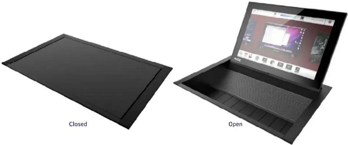
The HPX-MSP-10 / HydraPort Touch Connection Port with 10.1" Panel is a 10 Module HydraPort Connection Port with a 10.1" Modero S Series Touch Panel built into the cover. By combining device connectivity and room control into a single unit, the HPX-MSP-10 reduces clutter and saves space on the table top. Thanks to an elegant yet practical design, HPX-MSP-10 looks great in any room, from huddle spaces to large conference rooms. When closed, the unit sits flush with the table top to keep the meeting space neat and clean. When open, the unit provides easy access to the HydraPort modules and a full-featured Modero S Series Touch Panel.
The HPX-MSP-10 includes a specially designed, ultra-thin 10.1" control panel that includes all the great Modero S features, including a brilliant 24-color depth, PoE connectivity, video streaming, and VoIP support – all at an economical price point.
natural_image
Two black electronic devices labeled 'Closed' and 'Open', shown from front and side views (no text or symbols on the devices themselves)FIG. 3 HPX-MSP-10 (Open & Closed positions)
HPX-MSP-10 Specifications
| HPX-MSP-10 Specifications | |
| MODELS AVAILABLE: • HPX-MSP-10-SL, Silver: FG571-09• HPX-MSP-10-BL, Black: FG571-10 | |
| WEIGHT 5.75 lbs (2.15 Kg) | |
| Dimensions (HWD): | 4.567 (116mm) x 13.221 (335.82mm) x 8.488 (215.60mm) - see FIG. 8 on page 15 |
| Cutout Dimensions: Width: 11.008" (279.61mm), Length: 7.878" (200.10mm) | |
| POWER CONSUMPTION • Full-On: 14W (max)• T y p i c a l : 7 . 5 W• S t a n d b y : 4 . 5 W• Shutdown: 0.7W• Start-Up Inrush Current: Not applicable due to PoE standard | |
| EXTERNAL POWER SUPPLY REQUIRED | Optimal performance requires use of one of the following AMX PoE power supplies (not included):• PS-POE-AF-TC, PoE Injector, 802.3AF Compliant (FG423-83)• NXA-ENET8-2POE, Gigabit PoE Ethernet Switch (FG2178-63)Note: AMX does not support the use of non-AMX power supplies |
| TOUCH SCREEN DISPLAY | • Display Type: TFT Active Matrix Color LCD• Display Size (WH): Landscape: 9.1" x 5.9" (230mm x 149mm), 10.8" (274mm) diagonal• Viewable Area (WH): Landscape: 8.5" x 5.4" (217mm x 136mm ), 10.0" (256mm) diagonal• Resolution: Landscape: 1280x800• Aspect Ratio: Landscape: 16:9• Brightness: 350 cd/m2• Contrast Ratio: 800:1• Color Depth: 16.7M colors• Illumination: LED• T o u c h O v e r l a y : R e s l s t l v e |
| VIEWING ANGLE | 85°/85°/85°/85° (Up/Down/Left/Right) |
| HPX-MSP-10 Specifications (Cont.) | |
| MEMORY • SDRAM: 512 MB | • Flash : 4 GBMaximum Project Size: 2.4 GB flash available to user |
| COMMUNICATIONS • Ethernet: | 10/100 Auto MDI-X, RJ-45 connector.Supported IP and IP-Based Protocols: UCP, TCP, ICMP, ICSP, IGMP,DHCP, Telnet, FTP, DNS, RFB (for VNC), HTTPUSB: (1) USB host 2.0, Type A port: Firmware upgrade, touch panel file transfer, JPEG image viewer, HID PeripheralsBluetooth®: Mouse/Keyboard: HID Profile v1.1, requires MXA-BT, Bluetooth USB Adapter (FG5968-19) and MXA-HST, Bluetooth Handset (FG5968-17) |
| VIDEO • Supported Video Codecs: | MPEG2-TS: MPEG-2 Main Profile@High Level up to 720p at 25 fps (decode)MPEG-2-TS: H.264 High Profile@Layer 4, AAC-LC up to 720p at 25 fps (decode)MJPEG up to 720p at 25 fps (decode)Supported Video Transport Streams: MPEG-TS for MPEG2 and H.264; HTTP for MJPEGMax Number of Active Video Streams: One decode |
| AUDIO • Microphone: -42 dB ±3 dB sensitivity FET microphoneSpeakers: 4 ohm, 1.5 Watt, 500 Hz cutoff frequencySupported Audio Codecs:MP2 Layer I and II, MP3 (8 kHz, 11.025 kHz, 12 kHz, 16 kHz, 22.05 kHz, 24 kHz, 32 kHz, 44.1 kHz, 48 kHz)AAC-LC (8 kHz, 96 kHz)G.711 with μLaw (VoIP encode/decode at 8 kHz)File Formats: WAV, MP3 (as part of touch panel file only - no USB storage)Intercom: Full Duplex VoIP, SIP v2.0 (supported with AMX-CSG) | |
| GRAPHICS ENGINE | AMX G4: AMX's exclusive, powerful G4 graphics engine – the driving force behind the advanced graphics and image processing capability on a variety of AMX Touch Panels and other devices (see TPD4 Operations Guide for more information) |
| EMBEDDED APPLICATIONS • Remote Management: VNC Server, G4 Web ControlPanel-to-Panel Conferencing: Receives video and returns audio for panel-to-panel communicationAudio Conferencing: Audio (Full Duplex Intercom) | |
| FRONT PANEL COMPONENTS | Sleep Button: Sleep button to activate sleep mode and powering off. Also provides access to setup pages (can be disabled) |
| CONNECTIONS | • Ethernet: 10/100 port, RJ-45 connector• USB: (1) USB host 2.0, Type A portPower: PoE (Power over Ethernet), 802.3af, class 0 |
| ENVIRONMENTAL | • Temperature (Operating): 32°F to 104°F (0°C to 40°C)• Temperature (Storage): 4°F to 140°F (-20°C to 60°C)• Humidity (Operating): 20% to 85% RH• Humidity (Storage): 5% to 85% RH• Heat Dissipation: On: 27.3 BTU/hr, Standby: 10.9 BTU/hr |
| INCLUDED ACCESSORIES | • Cardstock Installation Cutout Template, 10" HydraPort Touch (68-0571-02)• 4 Side Clamps |
| OPTIONAL ACCESSORIES | • HPX-AC-TMPLT-MSP10, Aluminum Installation Router Guide for HPX-MSP-10 (FG559-96)• HydraPort Connectivity Modules - build your own custom configuration at www.amx.com/hydraportpreview |
| CERTIFICATIONS | • FCC Part 15 Class B• AS/NZS CISPR 22 Class B• EN 55022 Class B and EN 55024• I E C / E N - 60 9 5 0• RoHS/WEEE compliant |
Installing HPX Flip-Up Panels
Overview
Read these instructions in their entirety before beginning the installation.
CAUTION: his installation requires specific woodworking skills. This installation should be performed by an experienced person, comfortable with woodworking operations. Only a professional, AMX-qualified installer should perform this installation. Installation must conform to all local codes. This product may not be installed by the end-user.
1) Insert Additional HydraPort Connectivity Modules
Additional HydraPort Connectivity Modules are installed in the HPX-MSP-7/10 Base Assembly by sliding them on to the mounting rails (similar to other HPX Assemblies).
NOTE: Note: A typical installation will include several additional HydraPort Connectivity Modules. HydraPort Connectivity Modules often require backside termination. Refer to the installation guide for each Module for details. The backside termination for each Module can and should be completed before the Module is installed into the HPX-MSP-7/10 Base Assembly.
To access the mounting rails, remove either of the side covers from the HPX-MSP-7/10 Base Assembly:
- Remove the Philips-head Mounting Screws that secure the Side Cover to the HPX Base Assembly.
NOTE: Do not remove the two upper socket screws
- There are six Mounting Screws on the HPX-MXP-7 (FIG. 4):

FIG. 4 Removing the Side Cover (HPX-MSP-7)
- There are seven Mounting Screws on the HPX-MXP-10 (FIG. 4):

FIG. 5 Removing the Side Cover (HPX-MSP-10)
- Gently lift one end of the Side Cover to free it from the enclosure, then carefully pull the opposite side to remove it. Note that with the Side Cover removed, the mounting rails (inside the enclosure) are accessible (see FIG. 4).
- Slide the pre-terminated modules one at a time onto the mounting rails.
Note the orientation of each module: the faceplate on each HPX module has a tab on one side and a matching notch on the other. These tabs and notches allow the modules to interlock when installed. Ensure that the modules are oriented consistently, so that the faceplates are stacked and interlocked when the modules are installed on the mounting rails (see FIG. 6).

FIG. 6 Inserting Modules Into the HPX Base Assembly
Route the cables from each module up through the bottom of the base assembly.
NOTE: Refer to each HPX module's Installation Guide for installation and termination details.
- Replace the side cover on the HPX Base Assembly:
a. Insert the leading edge of the Slide Cover into the HPX Base Assembly enclosure.
b. Make sure that the Slide Cover is aligned with the tabs on the edge of the enclosure.
c. Gently press the other side of the Side Cover so that it snaps into place.
d. Replace all six Philips-head Mounting Screws.
2) Select a Suitable Location
Location Notes
- Always use an appropriate template (either the included Cardstock Cutout Template, or the optional HPX-AC-TMPLT-MSP7 or HPX-AC-TMPLT-MSP10 Aluminum Installation Router Guide) to establish the size of the hole needed to install the HPX-MSP-7/10. It is crucial to the installation that the cutout hole is located and sized properly.
- Take care to ensure that the system does not interfere with the normal use of the workspace. For example, on a table or work surface, ensure that the system does not interfere with the user's legs when they are seated at the table.
- If installing HydraPort Retractable Cable Modules, ensure that the pull-out length of the cable (1.5m) can reach all potential users, as excessively pulling on a fully extended cable can irreparably damage the retractor module.
• Refer to the Mounting Surface Requirements below:
Mounting Surface Requirements
| HPX-MSP-7/10 Mounting Surface Requirements | |
| Above Mounting Surface: 9.57" | x 10.55" x 4.53" (243mm x 268mm x 115mm) |
| Below Mounting Surface: 15.08" | x 11.54" x 6.26" (383mm x 293mm x 159mm) |
| Mounting Surface Thickness: Min: 0.5" (12.7mm) / Max: 2.0" (50mm) | |
HPX-MSP-7 Dimensions and Space Requirements
Note the dimensions and space requirements for installing the HPX-MSP-7 (FIG. 7).
![5.837" [148.25 mm] 6.526" [165.75 mm] 10.571" [268.51 mm] 9.159" [232.65 mm] 4.449" [113 mm] 4.567" [116 mm] 8.280" [210.30 mm]](/content/2026/05/907172/images/f72881cfea2e6684ba821c5c108b5de8402d1ee40287bfb41b9f3626387cbc9b.jpg)
FIG. 7 HPX-MSP-7 Dimensions
HPX-MSP-10 Dimensions and Space Requirements
Note the dimensions and space requirements for installing the HPX-MSP-10 (FIG. 7).
![7.799" [198.10 mm] 8.488" [215.60 mm] 13.221" [335.82 mm] 11.809" [299.96 mm] 4.449" [113 mm] 4.567" [116 mm] 10.930" [277.61 mm]](/content/2026/05/907172/images/8c6302af5ca0f8c1814fc6a6f24d1c23a4f4120b5f821824fb4a2a54aaea1a6d.jpg)
FIG. 8 HPX-MSP-10 Dimensions
3) Cut the Hole In the Mounting Surface
The HydraPort Touch Base Assembly comes with a Cardstock Installation Template that can be used to locate the perfect spot and to mark the perimeter for cutting the table surface. The following cutout dimensions are required for the HPX-MSP-7 Base Assembly:
| Cutout Dimensions | ||
| Width Length | ||
| HPX-MSP-7 8.358" (212.30mm) | 5.915" (150.25 mm) | |
| HPX-MSP-10 11.008" (279.61 mm) | 7.878" (200.10 mm) | |
CAUTION: Avoid creating a cutout that is smaller than the specified dimensions. If the cutout hole is cut too small, the HPX Base Assembly may be "squeezed" slightly when installed, which can adversely affect Flip-up motions due to friction.
-
Use the included Cardstock Installation Template to locate the desired position of the HydraPort Touch Base Assembly.
-
Use the Cardstock Installation Template to mark the edges of the cutout.
NOTE: Note: Very little clearance exists between the HydraPort Base Assembly and the hole cutout in the mounting surface.
- Align the cutout carefully with the edges or other features of the mounting surface. If the cutout is misaligned, the installed unit will be misaligned.
- Take care to ensure that the top surface of the mounting surface is not damaged beyond the width of the trim bezel as the cutout is made.
- Use an appropriate drill and drill bit to make a starting hole within the boundary of the cutout. Use an appropriate saw, such as a jigsaw to finish the cutout.
- Make sure cutting tool used is appropriate for the material to be cut and will not tear or chip the top surface.
- Note that the process of making the cutout will create substantial dust and prepare the environment appropriately.
4) Install the HPX-MSP-7/10 Into the Mounting Surface
The HPX-MSP-7 and HPX-MSP-10 both use four Side Clamps (included) to secure the unit to the mounting surface - no tools required;
- Run all cables that are connected to the installed HPX modules through the cutout in the mounting surface.
- Slide the HPX-MSP-7/10 into the cutout. Make sure that the top of the unit is level and nearly flush with the top of the mounting surface (FIG. 9):

FIG. 9 HPX Touch Installed in the mounting Surface cutout
Note that the trim around the top of the HPX covers the edges of the cutout hole.
- Use all four included Side Clamps to secure the HPX-MSP-7/10 to the mounting surface (FIG. 10):

FIG. 10 HPX Touch Assembly and Side Clamps
To slide a Side Clamp into one of the Clamp Slots on the side of the HPX base assembly:
Mounting Surface (bottom side)

FIG. 11 Side Clamp (X4)
a. Insert the Slide Clamp into a Clamp Slot on the HPX Base Assembly.
b. Press down on the Release Tab on the Side Clamp (see FIG. 10), and slide the clamp into the ratcheted Clamp Slot until it is contacts the underside of the mounting surface.
c. Release the Release Tab to lock the Clamp into position. To adjust the Clamp position in the Clamp Slot (or to remove the Clamp), press the Release Tab and move the Clamp as necessary. Do this for all four Side Clamps. Ensure that all four clamps are fully inserted, and are all touching the underside of the mounting surface.
d. Tighten the thumb screws on all four Clamps to secure the HPX assembly to the mounting surface (FIG. 12):

FIG. 12 Tighten the Side Clamps to secure the HPX to the Mounting Surface
- Repeat this process for the remaining three Side Clamps. All four clamps should be used.
- When all four Slide Clamps are installed, re-check each of the thumb screws and make sure they are all tight.
5) Connect Ethernet and USB Cables
Once the HPX unit is installed in the mounting surface, plug in the Ethernet and (optionally) USB cable. The Ethernet and USB ports are located on the bottom of the HPX unit (FIG. 13):
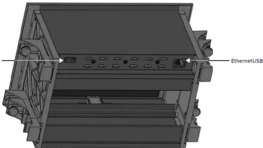
FIG. 13 HPX Bottom view - Ethernet and USB ports
- Ethernet: Connect to an 802.3AF compliant PoE power supply (PS-POE-AF-TC or NXA-ENET8-2POE, not included).
- USB: Can be used for up to four actions (two commissioning, and two for end users): Firmware upgrade, touch panel file transfer, JPEG image viewer, and HID Peripherals.
NOTE: For end user access to USB drive, use a single or double USB HydraPort module such as HPX-N100-USB or HPX-N102-USB. For end user HID peripheral such a mouse or keyboard, plug directly (or via a 3rd party USB hub) into the HPX Touch unit.
Secure Cables Beneath the Mounting Surface
Use the tie-wrap slots provided on the lower edge of each of the Side Covers (FIG. 14) to secure cabling to the HPX and modules, via the four included tie-wraps:

FIG. 14 HPX Bottom view - Ethernet and USB ports
Troubleshooting
Overview
The HPX-MSP-7/10 are designed to allow removal of the Touch Panel Assembly from the HPX Base without the need to remove the HPX Base from the mounting surface.
- It may be necessary to remove the Touch Panel Assembly to access the Spring Tension Adjust screw.
- In the rare event that the Modero Touch Panel in the HPX-MSP-7/10 needs servicing, it can removed from the HPX Base Assembly without removing other HPX Modules or uninstalling the HPX Base.
Removing the Touch Panel Assembly
1) Power Off the Panel and Disconnect Cables
Disconnect all cables (Ethernet/PoE and USB) from the HPX-MSP-7/10. The Ethernet and USB connectors are located on the bottom of the HPX unit (see FIG. 13 on page 17).
2) Remove the Touch Panel Assembly From the HPX Base Assembly
The Touch Panel Assembly is secured to the HPX Base Assembly with three Philips-head screws. These Touch Panel Assembly screws are located on the bottom surface of the panel, and are accessible from beneath the Base Assembly (FIG. 15):

FIG. 15 Removing the Touch Panel from the HPX Base Assembly
NOTE: FIG 15 shows an HPX-MSP-7, but the screw locations and lift-up procedure are the same for the HPX-MSP-10.
- From underneath the mounting surface, remove the three screws that secure the Touch Panel Assembly to the HPX Base (as shown in FIG. 15).
- Carefully lift the Touch Panel Assembly straight up and slide it out of the HPX Base.
Adjusting the Flip-Up Movement for the Panel
The HPX-MSP-7/10 use an internal spring mechanism to lift the touch panel to its raised position. When properly adjusted, the panel will lift smoothly until it is fully raised, without any rebound. The lift mechanism is factory-adjusted before shipping. In most cases there is no need to adjust the panel movement. However, in the case that an adjustment is needed, it is easily accomplished via the adjustable Lid Movement Adjust screws.
- If the panel does not lift fully to the raised position, it may be necessary to loosen the Lid Movement Adjust screws (to decrease resistance on the panel).
- If the panel flips up too quickly, it may be necessary to tighten the Lid Movement Adjust screws (to increase resistance on the panel).
1) Remove the Touch Panel Assembly from the HPX Base Assembly
It is necessary to remove the Touch Panel Assembly from the HPX Base Assembly to access the Lid Movement Adjust screws. Refer to the Removing the Touch Panel Assembly section on page 19.
2) Adjust the Lid Movement Adjust Screws
There is a Lid Movement Adjust screw located on each side of the Touch Panel Assembly. Note that there are three screws on the triangular side panels - the top screw is the Lid Movement Adjust screw (FIG. 16):

FIG. 16 Touch Panel Assembly - Lid Movement Adjust screws
Increasing Flip-Up Panel Motion Resistance
If the touch panel fails to lift completely to its raised position, try decreasing the resistance of panel movement by loosening the Lid Movement Adjust screws (one on each side of the Touch Panel Assembly):
- Turn the Lid Movement Adjust screws counter clock-wise to loosen the screw and decrease resistance.
- Repeat these adjustments until the touch panel flips-up completely and smoothly.
Decreasing Flip-Up Panel Motion Resistance
If the touch panel lifts too quickly to its raised position (which can cause the panel rebound slightly when it flips open), try increasing the resistance of panel movement by tightening the Lid Movement Adjust screws (one on each side of the Touch Panel Assembly):
- Turn the Lid Movement Adjust screws clock-wise to tighten the screw and increase resistance.
- Repeat these adjustments until the touch panel flips-up completely and smoothly.
NOTE: Limit each adjustment to quarter-turns, and be sure to adjust the Lid Movement Adjust screw on each side equally.
3) Replace the Touch Panel Assembly into the HPX Base Assembly
Once the Lid Movement Adjust screws have been adjusted, replace the Touch Panel Assembly into the HPX Base Assembly:
- Carefully slide the Touch Panel Assembly back into it's position in the HPX Base Assembly until it is fully seated in place.
- Replace the three Touch Panel Assembly screws (accessible from the beneath the HPX Base Assembly).

- HYDRAPORT TOUCH CONNECTION PORTS
- IMPORTANT SAFETY INSTRUCTIONS
- COPYRIGHT NOTICE
- LIABILITY NOTICE
- AMX WARRANTY AND RETURN POLICY
- ESD WARNING
- FCC AND CANADA EMC COMPLIANCE INFORMATION:
- EU COMPLIANCE INFORMATION:
- WEEE NOTICE:
- CHINA COMPLIANCE INFORMATION:
- Table of Contents
- HPX-MSP-7/10 HydraPort Touch Connection Ports 6
- HPX-MSP-7 7
- HPX-MSP-10 9
- Installing HPX Flip-Up Panels 11
- Troubleshooting 19
- HPX-MSP-7/10 HydraPort Touch Connection Ports
- Overview
- HPX-MSP-7
- HPX-MSP-10
- Installing HPX Flip-Up Panels
- 1) Insert Additional HydraPort Connectivity Modules
- 2) Select a Suitable Location
- Location Notes
- Mounting Surface Requirements
- HPX-MSP-7 Dimensions and Space Requirements
- HPX-MSP-10 Dimensions and Space Requirements
- 3) Cut the Hole In the Mounting Surface
- 4) Install the HPX-MSP-7/10 Into the Mounting Surface
- 5) Connect Ethernet and USB Cables
- Secure Cables Beneath the Mounting Surface
- Troubleshooting
- Removing the Touch Panel Assembly
- 1) Power Off the Panel and Disconnect Cables
- 2) Remove the Touch Panel Assembly From the HPX Base Assembly
- Adjusting the Flip-Up Movement for the Panel
- 1) Remove the Touch Panel Assembly from the HPX Base Assembly
- 2) Adjust the Lid Movement Adjust Screws
- Increasing Flip-Up Panel Motion Resistance
- Decreasing Flip-Up Panel Motion Resistance
- 3) Replace the Touch Panel Assembly into the HPX Base Assembly
Brand : AMX
Model : HPX-MSP-7-SL
Category : Touchscreen