
M09CR - Air conditioner Malmbergs - Free user manual and instructions
Find the device manual for free M09CR Malmbergs in PDF.


| Product Type | Portable Air Conditioner |
| Brand | Malmbergs |
| Model | M09CR |
| Cooling Capacity | 9000 BTU/h (2600 W) |
| Applicable Area | 14-20 m² |
| Air Flow | 420 m³/h |
| Sound Level | 46 dB |
| Energy Rating | A |
| Power Supply | 220-240 V~, 50 Hz, 1 Ph |
| Dimensions (W x H x D) | 430 x 720 x 320 mm |
| Net Weight | 29.5 kg |
| Protection Class | IP X0 |
| Operating Modes | Auto, Cool, Dry, Fan |
| Fan Speeds | Low, Med, High, Auto |
| Temperature Range (Cool) | 17-30°C (62-88°F) |
| Timer | Auto On/Off, 0-24 hours |
| Sleep Mode | Yes (gradual temperature change) |
| Swing Function | Manual and automatic louver control |
| Remote Control | Included (batteries: 2 x AAA) |
| Window Kit | Included for vertical or horizontal windows |
| Exhaust Hose | Included, length adjustable (30-120 cm) |
| Air Filter | Washable, clean every 2 weeks |
| Drainage | Manual bottom drain or continuous drain hose |
| Safety Features | Auto restart after power outage, 3-minute delay, error codes |
| Certification | CE |
Frequently Asked Questions - M09CR Malmbergs
User questions about M09CR Malmbergs
0 question about this device. Answer the ones you know or ask your own.
Ask a new question about this device
Download the instructions for your Air conditioner in PDF format for free! Find your manual M09CR - Malmbergs and take your electronic device back in hand. On this page are published all the documents necessary for the use of your device. M09CR by Malmbergs.
USER MANUAL M09CR Malmbergs
natural_image
Line drawing of a portable air conditioner unit with control panel and door (no text or symbols)SE
INNEHÅLL
Säkerhetsanvisningar ...... sida 3
Identification of Parts 28-29
Air Conditioner Features 30
Operation Instructions 31
Installation Instructions ....32-36
Care and Maintenance 37
Trouble Shooting 38
Technical Specifications 38
SE
Fig. 2
- Kontrollpanel
- Horisontell luftriktare (automatisk swing-funktion)
- Styrhjul
- Bärhandtag (båda sidor)
Baksida

Fig. 3
natural_image
Line drawing of a portable air conditioner unit with cooling fins and ventilation slots (no text or symbols)Driftsavbrott
natural_image
Line drawing of a cabinet or cabinet frame with a handle and side panel (no text or symbols)Fig. 16

Fig. 17
INSTALLATION I ETT SKJUTFÖNSTER
natural_image
Two cylindrical pipe fittings with curved arrows indicating rotation, no text or symbols presentFig. 18a Fig. 18b

natural_image
Technical line drawing of a mechanical device with a coiled spring and fan (no text or symbols)Fig. 20

natural_image
Diagram showing a device connected to a curved pipe with a diagonal line crossing it (no text or symbols present)Fig. 22
INSTALLATION AV UTBLÅSSLANG
natural_image
Diagram of a mechanical or electrical component with no visible text, numbers, or symbolsFig. 25
VATTENDRÄNERING
natural_image
Technical illustration of a mechanical device with internal components and directional arrows indicating motion (no text or symbols)Fig. 29
RENGÖRING OCH UNDERHÅLL
VIKTIGT
Kuva 2
Kuva 3
natural_image
Line drawing of a Kuva 5 air conditioner unit with cooling fan and ventilation slots (no text or symbols on device)Sähkökatko
natural_image
Line drawing of a cabinet or shelf unit with a handle and side panel (no text or symbols)
ASENNUS TYÖNTÖIKKUNAAN
natural_image
Two illustrations of a coiled tube with internal blades and curved arrows indicating rotation (no text or symbols)Kuva 18a Kuva 18b

natural_image
Technical line drawing of an air conditioning unit with coiled tubing and fan (no text or symbols)Kuva 20

natural_image
Diagram showing a device connected to a curved pipe with a diagonal line crossing it, no text or symbols present.Kuva 22
ULOSPUHALLUKSEN ASENTAMINEN
natural_image
Diagram of a mechanical or electrical component with no visible text, numbers, or symbolsKuva 25
VEDEN TYHJENNYS
natural_image
Technical illustration of a mechanical device with internal components and directional arrows indicating motion (no text or symbols)Kuva 29
PUHDISTUS JA HUOLTO
TÄRKEÄÄ
In this manual you will find many helpful hints on how to use and maintain your air conditioner properly. Just a little preventative care on your part can save you a great deal of time and money over the life of your air conditioner. Before operating this product, please read the instructions carefully and save this manual for future reference.
SAFETY PRECAUTIONS
SAFETY RULES
To prevent injury to the user or other people and property damage, the following instructions must be followed. Incorrect operation due to ignoring of instructions may cause harm or damage.
ALWAYS DO THIS
Your air conditioner should be used in such a way that it is protected from moisture, e.g. condensation, splashed water etc. Do not place or store your air conditioner where it can fall or be pulled into water or any other liquid. Unplug immediately.
Always transport your air conditioner in a vertical • position and stand on a stable, level surface during use.
Turn off the product when not in use.
Always contact a qualified person to carry out • repairs. If the supply cord is damaged it must be repaired by a qualified repairer.
Keep an air path of at least 30 cm all around the • unit from walls, furniture and curtains.
If the air conditioner is knocked over during use, • turn off the unit and unplug from the mains supply immediately.
NEVER DO THIS
Do not operate your air conditioner in a wet room • such as a bathroom or laundry room.
Do not touch the unit with wet or damp hands or • when barefoot.
Do not press the buttons on the control panel with • anything other than your fingers.
Do not remove any fixed covers. Never use this • appliance if it is not working properly, or if it has been dropped or damaged.
Never use the plug to start and stop the unit. • Always use the switch on the control panel.
Do not cover or obstruct the inlet or outlet grilles.
Do not use chemicals to clean or come in to contact with the unit. Do not use the unit in the presence of inflammable substances or vapour such as alcohol, insecticides, petrol, etc.
Do not allow children to operate the unit unsupervised.
- Do not use this product for functions other than those described in this instruction manual.
ENERGY SAVE
- Locate the unit where furniture cannot obstruct the air flow.
- Keep blinds/curtains closed during the sunniest part of the day.
- Keep the filters clean.
- Keep doors and windows closed to keep cool air in and warm air out.
OPERATING CONDITION
The air conditioner must be operated within the temperature range indicated below:
| Mode | Room Temperature |
| Cool | ≥ 17^ (62°F) |
| Dry | ≥ 13^ (54°F) |
SUGGESTED TOOLS FOR WINDOW KIT INSTALLATION
- Screwdriver (medium size Phillips)
- Tape measure or ruler
- Knife or scissors
- Saw (in the event that the window kit needs to be cut down in size because the window is too narrow for direct installation)
IDENTIFICATION OF PARTS
WARNING FOR YOUR SAFETY
- Do not store or use gasoline or other flammable vapours and liquids in the vicinity of this or any other appliance.
- Avoid fire hazard or electric shock. Do not use an extension cord or an adaptor plug. Do not remove any prong from the power cord.
WARNING ELECTRICAL INFORMATION
- Be sure the electrical service is adequate for the model you have chosen. This information can be found on the serial plate, which is located on the side of the cabinet and behind the grille.
- Be sure the air conditioner is properly grounded. To minimize shock and fire hazards, proper grounding is important. The power cord is equipped with a three-prong grounding plug for protection against shock hazards.
- Your air conditioner must be used in a grounded wall socket. The wall socket must not be equipped with a timer.
Ensure that the wall socket is accessible after the unit installation.
ACCESSORIES
| Parts Parts Name | Quantity | |
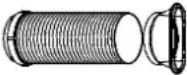 | Exhaust hose and adaptor B (flat mouth) 1 set | |
| [G2xH] | Adaptor B (round mouth) 1 set | |
 | Wall exhaust adaptor A 1 pc | |
 | Expansion plug and wooden screw 4 pcs | |
 | Window slider kit | 1 set |
 | Foam seal | 3 pcs |
 | Remote control | 1 pc |
 | Battery (for remote control) | 2 pcs |
Check that all the accessories are included in the package and please refer to the installation instructions for their usage.
NAME OF PARTS
Front

Fig. 2
- Operation Panel
- Horizontal Louver Blade (swings automatically)
- Caster Wheel
- Carrying Handle (both sides)
Rear
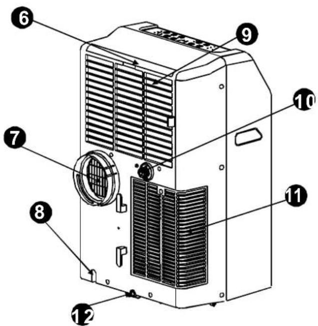
Fig. 3
- Upper Air Filter (behind the grille)
- Air Outlet
- Power Cord Outlet
- Air Intake
- Drain Outlet
- Air Intake
- Bottom Tray Drain Outlet
AIR CONDITIONER FEATURES
Before you begin, thoroughly familiarize yourself with the control panel and remote control and all its functions, then follow the symbol for the functions you desire.
The unit can be controlled by the unit control panel alone or with the remote control.
NOTE: This manual does not include Remote Control Operations, see the 'Remote Control Instruction' packed with the unit for details.
OPERATION PANEL OF THE AIR CONDITIONER

1. MODE select button
Selects the appropriate operating mode. Each time you press the button, a mode is selected in a sequence that goes from AUTO, COOL, DRY and FAN. The mode indicator light illuminates under the different mode settings. Fig. 4.
2. TIMER button
Used to initiate the AUTO ON start time and AUTO OFF stop time program, in conjunction with the ▲ and ▼ buttons.
3. POWER button
Power switch on/off.
4. SLEEP button
Used to initiate the SLEEP operation.
5. FAN button
Controls the fan speed. Press to select the fan speed in four steps: LOW, MED, HI and AUTO. The fan speed indicator light illuminates under different fan settings except under AUTO speed. When AUTO fan speed is selected, all the fan indicator lights turn dark.
6. UP ▲ and DOWN ▼ buttons
Used to adjust the temperature settings in 1^ C ( 2^ F) increments, in a range of 17^ C ( 62^ F) to 30^ C ( 88^ F) or the TIMER setting in a range of 0-24 hrs.
NOTE: The control is capable of displaying temperature in degrees Fahrenheit or degrees Celsius. To convert from one to the other, press and hold the Up and Down buttons at the same time, for 3 seconds.
7. LED Display
Shows the set temperature in "°C" or "°F" and Auto-timer settings. While on DRY and FAN modes, it shows the room temperature.
Error codes
E1- Room temperature sensor error
Unplug the unit and plug it back in. If error repeats, call for service.
E2- Evaporator temperature sensor error
Unplug the unit and plug it back in. If error repeats, call for service.
E3- Display panel communication error
Unplug the unit and plug it back in. If error repeats, call for service.
P1- Bottom tray is full
Connect the drain hose and drain the collected water away. If error repeats, call for service.
8. SWING button
When the operation is ON, press the SWING button to stop the louver at the desired angle. The moving angle of the louver is 6^ for each press. Keep pressing the button without releasing for more than 2 seconds, will activate the auto swing feature.
OPERATING INSTRUCTIONS
COOL OPERATION
Press the "MODE" button until the "COOL" indicator light comes on.
Press the ADJUST buttons ▲ or ▼ to select your desired room temperature. The temperature can be set within a range of 17-30°C (62-88°F).
Press the "FAN SPEED" button to choose the fan • speed.
DRY OPERATION
Press the "MODE" button until the "DRY" indicator light comes on.
Under this mode, you cannot select a fan speed or adjust the temperature. The fan motor operates at LOW speed.
Keep windows and doors closed for the best dehu- midifying effect.
Do not put the duct to window.
AUTO OPERATION
When you set the air conditioner in AUTO mode, it will automatically select cooling or fan only operation depending on what temperature you have selected and the room temperature.
The air conditioner will control room temperature • automatically round the temperature point set by you.
Under AUTO mode, you cannot select the fan • speed.
FAN OPERATION
Press the "MODE" button until the "FAN" indicator light comes on.
Press the "FAN SPEED" button to choose the fan • speed. The temperature cannot be adjusted.
Do not put the duct to window.
TIMER OPERATION
When the unit is on, first press the Timer button, the TIMER OFF indicator light illuminates. It indicates that the Auto Stop program is initiated.
- When the unit is off, first press the Timer button, the TIMER ON indicator light illuminates. It indicates that the Auto Start program is initiated.
- Press or hold the UP or DOWN button to change the Auto time by 0.5 hour increments, up to 10 hours, then at 1 hour increments up to 24 hours. The control will count down the time remaining until start.
- The selected time will register in 5 seconds and the system will automatically revert back to display the previous temperature setting.
Turning the unit ON or OFF at any time or adjust- ing the timer setting to 0.0 will cancel the Auto Start/Stop timed program.
- When the malfunction (E1 or E2) occurs, the Auto Start/Stop timed program will also be cancelled.
SLEEP OPERATION
Press this button, the selected temperature will increase by 1^ C ( 2^ F) during 30 minutes. The temperature will then increase by another 1^ C ( 2^ F) after an additional 30 minutes. This new temperature will be maintained for 7 hours before it returns to the originally selected temperature. This ends the Sleep mode and the unit will continue to operate as originally programmed.
Note: This feature is unavailable under FAN or DRY mode.
OTHER FEATURES
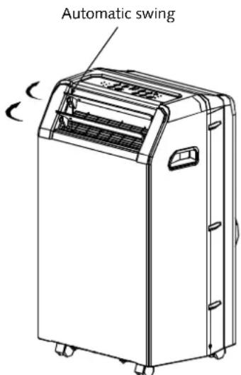
Fig. 5
Power Outage
In the case of a power outage or interruption, the unit will automatically re-start, in the settings last used, after the power is restored.
Wait 3 minutes before resuming operation
After the unit has stopped, it cannot be restarted in the first 3 minutes. This is to protect the unit. Operation will automatically start after 3 minutes.
Adjust the air flow direction automatically
- When operation is ON, the louver opens fully. Use the SWING button on the remote control to stop the louver at the desired angle.
- The louver move up to an angle of 6^ for each press until it move to a position which would affect the cooling effect of the air conditioner, it would automatically change the swing direction.
- Keep pressing the button without releasing for more than 2 seconds, will activate the auto swing feature. The louver swings as shown in Fig. 5.
INSTALLATION INSTRUCTIONS


LOCATION
The air conditioner should be placed on a firm foundation to minimize noise and vibration. For safe and secure positioning, place the unit on a smooth, level floor strong enough to support the unit.
The unit has caster wheels to aid placement, but it should only be rolled on smooth, flat surfaces. Use caution when rolling on carpet surfaces. Do not attempt to roll the unit over objects.
The unit must be placed within reach of a properly rated grounded socket.
Never place any obstacles around the air inlet or outlet of the unit.
Allow at least 30 cm of space from the wall for efficient air-conditioning.
WINDOW KIT INSTALLATION
Your window kit has been designed to fit most standard "vertical" and "horizontal" window applications.
However, it may be necessary for you to improvise/modify some aspects of the installation procedures for certain types of windows. Please refer to Fig. 8 and Fig. 9 for minimum and maximum window openings.


Window stool
Fig. 12

Fig. 13
INSTALLATION IN A DOUBLE-HUNG SASH WINDOW
- Cut the foam seal (adhesive type) to the proper length and attach it to the window stool. Fig. 10.
- Attach the window slider kit to the window stool. Adjust the length of the window slider kit according to the width of window, short the adjustable window kit if the width of window is less than 68.5 cm (27"). Open the window sash and place the window slider kit on the window stool. Fig. 11.
- Cut the foam seal (adhesive type) to the proper length and attach it on the top of the window. Fig. 12.
- Close the window sash securely against the window.
- Cut the foam seal to an appropriate length and seal the open gap between the top window sash and outer window sash. Fig. 13.

Fig. 14

Fig. 15

natural_image
Line drawing of a cabinet or cabinet frame with a handle and side panel (no text or symbols)Fig. 16

Fig. 17
INSTALLATION IN A SLIDING SASH WINDOW
- Cut the foam seal (adhesive type) to the proper length and attach it to the window frame. Fig. 14.
- Attach the window slider kit to the window stool. Adjust the length of the window slider kit according to the width of window, short the adjustable window kit if the width of window is less than 27 inches. Open the window sash and place the window slider kit on the window stool. Fig. 15.
- Cut the foam seal (adhesive type) to the proper length and attach it on the top of the window. Fig. 16.
- Close the sliding sash securely against the window.
- Cut the foam seal to an appropriate length and seal the open gap between the top window sash and outer window sash. Fig. 17.

natural_image
Two cylindrical pipe fittings with curved arrows indicating rotation (no text or symbols)Fig. 18a Fig. 18b

natural_image
Technical line drawing of an air conditioning unit with coiled tubing and fan (no text or symbols)Fig. 20
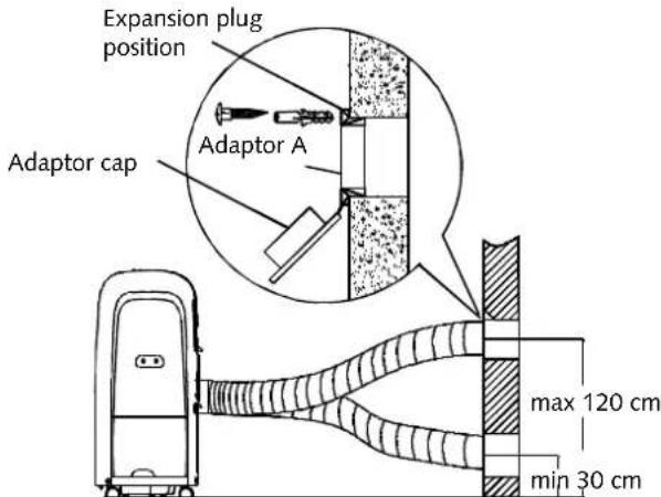
Fig. 21

natural_image
Diagram showing a device connected to a curved pipe with a diagonal line crossing it, no text or symbols present.Fig. 22
EXHAUST HOSE INSTALLATION
The exhaust hose and adaptor must be installed or removed in accordance with the usage mode.
| COOL mode Install | |
| FAN mode Remove | |
| DEHUMIDIFY mode Remove |
-
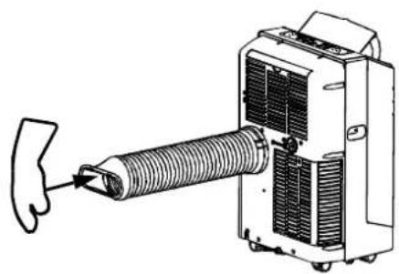
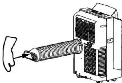
Install the window Exhaust adaptor B onto the exhaust hose as shown in Fig. 18a. or Fig. 18b. Refer to the previous pages for window kit installation.
-
Place the exhaust hose against the air outlet opening hook (See Fig. 19). When installing the exhaust hose, in order to install easily, the exhaust hose should be kept straight. Do not bend the hose (See Fig. 20).
The exhaust hose can be installed into the wall
-
Prepare a hole in the wall. Install the wall Exhaust adaptor A onto the wall (outside) by using 4 expansion plugs and wooden screws, be sure to fix thoroughly (See Fig. 21).
-
Attach the Exhaust hose to the Wall exhaust adaptor A.
Note: Cover the hole using the adaptor cap when not in use.
The duct can be compressed or extended moderately according to the installation requirement, but it is desirable to keep the duct length to a minimum.
IMPORTANT:
Do not over bend the duct (See Fig. 22).
natural_image
Diagram of a mechanical or electrical component with no visible text, numbers, or symbolsFig. 25
WATER DRAINAGE
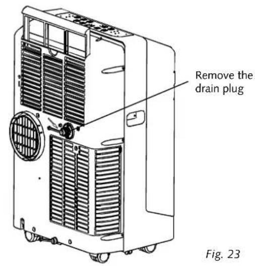
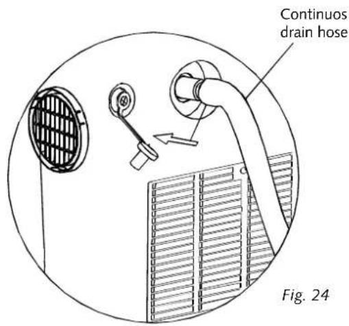
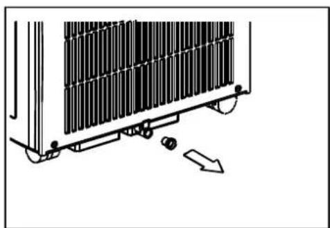
During dehumidifying mode, remove the drain • plug from the back of the unit, install the drain connector (5/8" universal female mender) with 3/4" hose (locally purchased). For the models without drain connector, just attach the drain hose to the hole. Place the open end of the hose directly over the drain area in your basement floor. Please refer to Fig. 23 and 24.
When the water level of the bottom tray reaches • a predetermined level, the unit beeps 8 times, the digital display area shows "P1". At this time the air conditioning/dehumidification process will immediately stop. However, the fan motor will continue to operate (this is normal).
Carefully move the unit to a drain location, remove the bottom drain plug and let the water drain away (Fig. 25). Restart the machine until the "P1" symbol disappears. If the error repeats, call for service.

Remove the
screw and take
the air inlet
grille down

natural_image
Technical line drawing of a portable air conditioner unit with cooling fan and ventilation slots (no text or labels)Fig. 27


natural_image
Technical illustration of a mechanical component with internal structure and directional arrows (no text or symbols)Fig. 29
CARE AND MAINTENANCE
IMPORTANT
1) Be sure to unplug the unit before cleaning or servicing.
2) Do not use gasoline, thinner or other chemicals to clean the unit.
3) Do not wash the unit directly under a tap or using a hose. It may cause electrical danger.
4) If the power cord is damaged, it should be repaired by the manufacturer or its agency.
AIR FILTER
Clean the air filter at least once every two weeks • to prevent inferior fan operation because of dust.
Removal•
This unit has two filters. Grasp the upper filter tab (Fig. 26), pull the filter "out" then "up". Remove the lower filter by loosening the screw, taking down the air inlet grille, then removing the air filter as shown in Fig. 27 and 28.
Cleaning•
Wash the air filter by immersing it gently in warm water, about 40^ C ( 104^ F), with neutral detergent. Rinse the filter and dry it in a shady place.
Mounting•
Insert the upper air filter from above after cleaning, attach the lower air filter on the air inlet grille, then install the grille by using the screw.
UNIT ENCLOSURE
Use a soft cloth soaked with neutral detergent to • clean the unit enclosure. Finish by wiping the unit with a dry clean cloth.
STORAGE
Remove the rubber plug at the back of the unit • and attach a hose to drain outlet. Place the open end of the hose directly over the drain area in your basement floor (See Fig. 23 and 24).
Remove the plug from the bottom drain outlet, • all the water in bottom tray would drain out (See Fig. 25).
- Keep the appliance running on FAN mode for half a day in a warm room to dry the appliance inside and prevent mold forming.
- Stop the appliance and unplug it.
- Remove the batteries from the remote control.
- Clean the air filter and reinstall it.
- Unscrew the exhaust hose to the right or left and pull out for disassembling (Fig. 29), and cover the window (wall) hole with the adaptor cap.
TROUBLE SHOOTING
| Troubles Possible Causes | Suggested Remedies | |
| Unit does not start when pressing the on/off button | P1 appears in the display window Drain the | water in the bottom tray |
| Room temperature is lower than the set temperature (cooling mode) | Reset the temperature | |
| Not cool enough The wind | lows or doors in the room are not closed | Make sure all the windows and doors are closed |
| There are heat sources inside the room Rem | move the heat sources if possible | |
| Exhaust air duct is not connected or blocked | Connect the duct and make sure it can function properly | |
| Temperature setting is too high Decrease the | set temperature | |
| Air filters are blocked by dust Clean the air filters | ||
| Noisy or vibration The ground is not level or not flat enough Place the unit on a flat, level ground if possible | ||
| Gurgling sound The sound comes from the flowing of the refrigerant inside the air-conditioner | It is normal | |
TECHNICAL SPECIFICATIONS
Power supply: 220-240V\~, 50Hz, 1 Ph
Cooling capacity: 9000BTU/h 2600W
Applicable area: 14-20 m²
Sound level: 46dB
Air flow: 420 m^3/h
Energy rating: A
Dims WxHxD: 430x720x320 mm
Net weight: 29.5 kg
Protection class: IP X0
Note
The rating data indicated on the energy label is based on the testing condition of installing the un-extended air exhaust duct without adaptor A and B (The duct and the adaptor A and B are listed in the accessories chart of the Instruction Manual).

CE
MALMBERGS
- SE
- INNEHÅLL
- Baksida
- Driftsavbrott
- INSTALLATION I ETT SKJUTFÖNSTER
- INSTALLATION AV UTBLÅSSLANG
- VATTENDRÄNERING
- RENGÖRING OCH UNDERHÅLL
- VIKTIGT
- Sähkökatko
- ASENNUS TYÖNTÖIKKUNAAN
- ULOSPUHALLUKSEN ASENTAMINEN
- VEDEN TYHJENNYS
- PUHDISTUS JA HUOLTO
- TÄRKEÄÄ
- SAFETY PRECAUTIONS
- SAFETY RULES
- ALWAYS DO THIS
- NEVER DO THIS
- ENERGY SAVE
- OPERATING CONDITION
- SUGGESTED TOOLS FOR WINDOW KIT INSTALLATION
- IDENTIFICATION OF PARTS
- WARNING FOR YOUR SAFETY
- WARNING ELECTRICAL INFORMATION
- NAME OF PARTS
- AIR CONDITIONER FEATURES
- MODE select button
- TIMER button
- POWER button
- SLEEP button
- FAN button
- UP ▲ and DOWN ▼ buttons
- LED Display
- Error codes
- E1- Room temperature sensor error
- E2- Evaporator temperature sensor error
- E3- Display panel communication error
- P1- Bottom tray is full
- SWING button
- OPERATING INSTRUCTIONS
- COOL OPERATION
- DRY OPERATION
- AUTO OPERATION
- FAN OPERATION
- TIMER OPERATION
- SLEEP OPERATION
- OTHER FEATURES
- Power Outage
- Wait 3 minutes before resuming operation
- Adjust the air flow direction automatically
- INSTALLATION INSTRUCTIONS
- LOCATION
- WINDOW KIT INSTALLATION
- INSTALLATION IN A DOUBLE-HUNG SASH WINDOW
- INSTALLATION IN A SLIDING SASH WINDOW
- EXHAUST HOSE INSTALLATION
- The exhaust hose can be installed into the wall
- IMPORTANT:
- WATER DRAINAGE
- CARE AND MAINTENANCE
- IMPORTANT
- AIR FILTER
- Removal•
- Cleaning•
- Mounting•
- UNIT ENCLOSURE
- STORAGE
- TROUBLE SHOOTING
- TECHNICAL SPECIFICATIONS
- Note
- MALMBERGS
Brand : Malmbergs
Model : M09CR
Category : Air conditioner