
VRM640C - Refrigerator INDESIT - Free user manual and instructions
Find the device manual for free VRM640C INDESIT in PDF.




| Product type | Ceramic hob built-in |
| Brand | INDESIT |
| Model | VRM640C |
| Dimensions (W x D x H) | 590 x 510 x 55 mm |
| Weight | 9 kg |
| Electrical supply | 220-240 V ~ 50/60 Hz, single-phase |
| Total power | 6200 W |
| Number of cooking zones | 4 radiant zones |
| Expandable zones | Yes (dual cooking zone) |
| Residual heat indicator | Yes, for each zone |
| Controls | 4 rotary knobs with 12 power levels |
| Cooking types | Traditional and expandable radiant zones |
| Cleaning | Damp sponge, scraper for soil, special ceramic hob cleaners |
| Surface material | Ceramic glass |
| Frame | Stainless steel (models with frame) |
| General safety | Automatic shut-off not specified, residual heat indicator, do not use barefoot |
| Installation | Built-in with hook and centering spring fixing |
| Intended use | Domestic, food cooking |
| Standards | CE (2006/95/EC, 2004/108/EC, 93/68/EEC) |
Frequently Asked Questions - VRM640C INDESIT
User questions about VRM640C INDESIT
0 question about this device. Answer the ones you know or ask your own.
Ask a new question about this device
Download the instructions for your Refrigerator in PDF format for free! Find your manual VRM640C - INDESIT and take your electronic device back in hand. On this page are published all the documents necessary for the use of your device. VRM640C by INDESIT.
USER MANUAL VRM640C INDESIT
Electrical connection
Description of the appliance, 21
Switching on the glass ceramic hob
Precautions and tips, 22
Practical advice on using the appliance
General safety
Disposal
Care and maintenance, 23
Switching the appliance off
Cleaning the appliance
Disassembling the hob
Technical description of the models, 24
! Before operating your new appliance please read this instruction booklet carefully. It contains important information concerning the safe operation, installation and maintenance of the appliance.
! Please keep these operating instructions for future reference. Pass them on to any new owners of the appliance.
Positioning
Keep all packaging material out of the reach of children. It may present a choking or suffocation hazard (see Precautions and tips).
The appliance must be installed by a qualified professional in accordance with the instructions provided. Incorrect installation may cause harm to people and animals or may damage property.
Built-in appliance
Use a suitable cabinet to ensure that the appliance functions properly.
- The supporting surface must be heat-resistant up to a temperature of approximately 100°C.
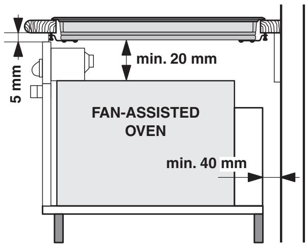
- If the appliance is to be installed above an oven, the oven must be equipped with a forced ventilation cooling system.
- Avoid installing the hob above a dishwasher: if this cannot be avoided, place a waterproof separation device between the two appliances.
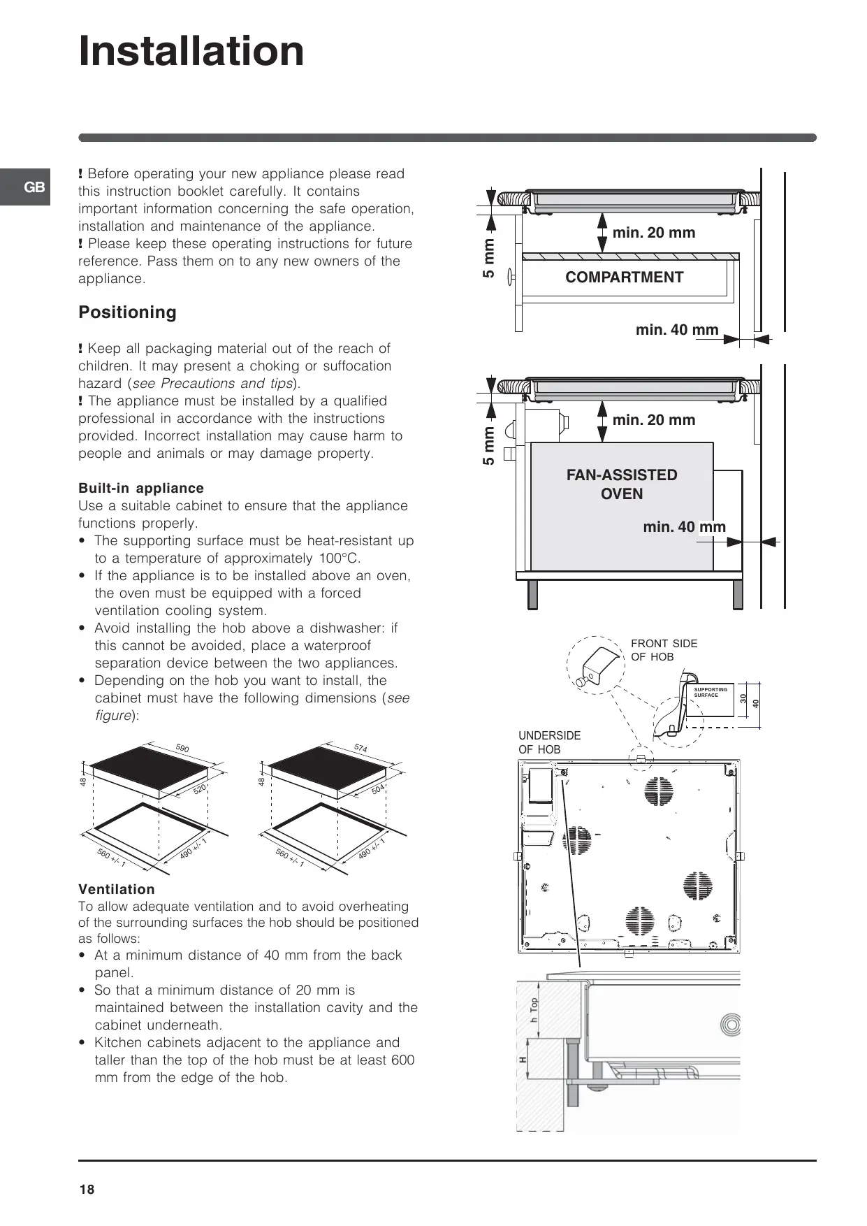
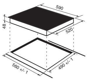
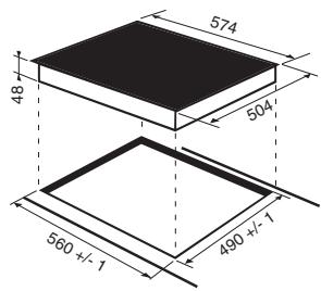
- Depending on the hob you want to install, the cabinet must have the following dimensions (see figure):
Ventilation
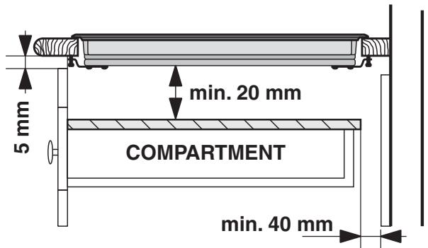
To allow adequate ventilation and to avoid overheating of the surrounding surfaces the hob should be positioned as follows:
- At a minimum distance of 40 mm from the back panel.
- So that a minimum distance of 20 mm is maintained between the installation cavity and the cabinet underneath.
- Kitchen cabinets adjacent to the appliance and taller than the top of the hob must be at least 600 mm from the edge of the hob.

Fixing
The appliance must be installed on a perfectly level supporting surface.
Any deformities caused by improper fixing could affect the features and operation of the hob.
The thickness of the supporting surface should be taken into account when choosing the length of the screws for the fixing hooks:
• 30 mm thick: 17.5 mm screws • 40 mm thick: 7.5 mm screws
Fix the hob as follows:
- Use short flat-bottomed screws to fix the 4 alignment springs in the holes provided at the central point of each side of the hob.
- Place the hob in the cavity, make sure it is in a central position and push down on the whole perimeter until the hob is stuck to the supporting surface.
- For hobs with raised sides: After inserting the hob into its cavity, insert the 4 fixing hooks (each has its own pin) into the lower edges of the hob, using the long pointed screws to fix them in place, until the glass is stuck to the supporting surface.
! The screws for the alignment springs must remain accessible. ! In order to adhere to safety standards, the appliance must not come into contact with electrical parts once it has been installed. ! All parts which ensure the safe operation of the appliance must not be removable without the aid of a tool.
Electrical connection
! The electrical connection for the hob and for any built-in oven must be carried out separately, both for safety purposes and to make extracting the oven easier.
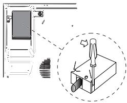
Terminal board
UNDERSIDE OF HOB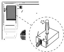
On the lower part of the appliance there is a connection box for the different types of electricity supply (the picture is only an indication and is not an exact representation of the purchased model).
Single-phase connection
The hob is equipped with a pre-connected electricity supply cable, which is designed for single-phase connection. Connect the wires in accordance with the instructions given in the following table and diagrams:
| Voltage and mains frequency | Electrical cable | Wire connection |
| 220-240V 1+N ~ 50/60 Hz | 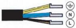 | ± : yellow/greenN: the two blue wires togetherL: brown and black together |
Other types of connection
If the mains supply corresponds with one of the following:
Voltage and mains frequency
- 400V - 2+N \~ 50/60 Hz • 220-240V 3 \~ 50/60 Hz
- 400V - 2+2N \~ 50/60 Hz
Separate the wires and connect them in accordance with the instructions given in the following table and diagrams:
| Voltage and mains frequency | Electrical cable | Wire connection |
| 400V - 2+N ~50/60 Hz220-240V 3 ~50/60 Hz | 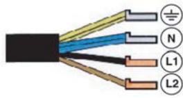 | ± : yellow/green; N : the two blue wires together L1 : black L2 : brown |
| 400V - 2+2N ~50/60 Hz | ± : yellow/green; N1 : blue N2 : blue L1 : black L2 : brown |
If the mains supply corresponds with one of the following: Voltage and mains frequency
- 400V 3 - N \~ 50/60 Hz
proceed as follows:
! The cable provided is not suitable for the following types of installation.
- Use a suitable supply cable, H05RR-F or higher, with the right dimensions (cable cross section: 25 mm).
- To open the terminal board, use a screwdriver as a lever under the side tabs of the cover (see Terminal board picture).
- Loosen the cable clamp screw and the terminal board screws in accordance with the type of connection required and position the connection supports as shown in the following table and diagrams.
- Position the wires in accordance with the information given in the following table and diagrams and connect the appliance by tightening all the screws for the springs as much as possible.
| Voltage and mains frequency | Electrical connections | Terminal board |
| 400V 3-N ~50/60 Hz | 1 2 3 4 5L1 L2 L3 N | Three-phase 400 |
- Secure the power supply cable by fastening the cable clamp screw, then put the cover back on.
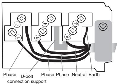
Three-phase 400
Connecting the electricity supply cable to the mains
If the appliance is being connected directly to the electricity mains, an omnipolar switch must be installed with a minimum opening of 3 mm between contacts.
! The installer must ensure that the correct electrical connection has been made and that it is fully compliant with safety regulations.
Before connecting the appliance to the power supply, make sure that:
- The appliance is earthed and the plug is compliant with the law.
- The socket can withstand the maximum power of the appliance, which is indicated on the data plate located on the appliance itself.
- The voltage falls within the range of values indicated on the data plate.
- The socket is compatible with the plug of the appliance. If the socket is incompatible with the plug, ask an authorised technician to replace it. Do not use extension cords or multiple sockets.
! Once the appliance has been installed, the power supply cable and the electrical socket must be easily accessible.
! The cable must not be bent or compressed.
! The cable must be checked regularly and replaced by authorised technicians only.
! The manufacturer declines any liability should these safety measures not be observed.
! Do not remove or replace the power supply cable for any reason. Its removal or replacement will void the warranty and the CE marking. INDESIT does not assume liability for accidents or damage arising from replacement/removal of the original power supply cable. Replacement can only be accepted when carried out by personnel authorised by INDESIT and using an original spare part.
Switching on the glass ceramic hob
Traditional cooking zones
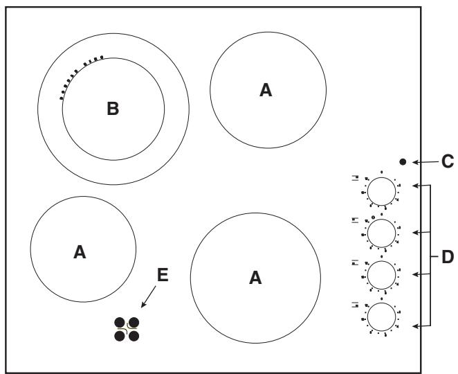
Traditional cooking zones (A) consist of circular heating elements. They turn red approximately ten seconds after they have been switched on.
Each cooking zone is fitted with a control knob (D) which allows you to select from 12 different temperature settings between a minimum of 1 and a maximum of 12.
Extendable cooking zones
The extendable radiant elements (B) are distinguished by the fact that they have a double heating zone. You can switch the smaller internal cooking zone on its own, or both the external and internal zones.
The control knob (D) allows you to choose between two power levels, which may both be adjusted between a minimum value of 1 and a maximum of 12:
- The lowest power level can be set by turning the knob clockwise from 1 to 12.
- Turn the knob completely round (◎), until you hear a slight click, to enable the maximum power level. This in turn can be adjusted to a value between 12 and 1 by turning the knob anticlockwise. To restore the minimum power level, turn the knob and set it back to position 0. For double cooking zones, the first part of the knob movement activates the smaller (internal) cooking zone. To activate both (internal and external), it is necessary to turn the knob completely (◎) and then select the desired power level between 12 and 1.
Recommended power levels for various types of cooking:
| Set. | Radiant Burner |
| 0 | Off. |
| 1 | To melt butter and chocolate. |
| 2 | To heat liquids. |
| 3 | |
| 4 | For creams and sauces. |
| 5 | |
| 6 | For cooking at the boiling point. |
| 7 | |
| 8 | For Roasts. |
| 9 | |
| 10 | For boiling large pieces of meat. |
| 11 | |
| 12 | For frying. |
| For utilising both cooking areas. |
Operation indicator light (C)
This is illuminated when a heating zone has been activated.
Residual heat indicator light (E)
This indicates that one or more cooking zones are at a temperature greater than 60°C, even after the cooking zones have been switched off. Some models have 4 residual heat indicator lights, one for each cooking zone.
This appliance has been designed and manufactured in compliance with international safety standards. The following warnings are provided for safety reasons and must be read carefully.
CE This appliance conforms to the following European Economic Community directives:
- 2006/95/EEC dated 12/12/06 (Low Voltage) and subsequent amendments; -2004/108/EEC dated 15/12/04 (Electromagnetic Compatibility) and subsequent amendments;
- 93/68/EEC dated 22/07/93 and subsequent amendments.
General safety
Make sure that the air inlet behind the fan grille is never obstructed. The built-in hob should, in fact, be provided with suitable ventilation for the cooling of the electronic components used in the appliance.
- The appliance was designed for domestic use inside the home and is not intended for commercial or industrial use.
- The appliance must not be installed outdoors, even in covered areas. It is extremely dangerous to leave the appliance exposed to rain and storms.
- Do not touch the appliance when barefoot or with wet or damp hands and feet.
- The appliance must be used by adults only for the preparation of food, in accordance with the instructions outlined in this booklet. Any other use of the appliance (e.g. for heating the room) constitutes improper use and is dangerous. The manufacturer may not be held liable for any damage resulting from improper, incorrect and unreasonable use of the appliance.
- Do not use the hob as a worktop or chopping board.
- The glass ceramic hob is resistant to mechanical shocks, but it may crack (or even break) if hit with a sharp object such as a tool. If this happens, disconnect the appliance from the electricity mains immediately and contact a Service Centre.
- Ensure that power supply cables of other electrical appliances do not come into contact with the hot parts of the hob.
- Remember that the cooking zones remain relatively hot for at least thirty minutes after they have been switched off. An indicator light provides a warning when residual heat is present (see Start-up and use).
- Keep any object which could melt away from the hob, for example plastic and aluminium objects, or products with a high sugar content. Be especially careful when using plastic film and aluminium foil or packaging: if placed on surfaces which are still hot, they may cause serious damage to the hob.
- Always make sure that pan handles are turned towards the centre of the hob in order to avoid accidental burns.
- When unplugging the appliance, always pull the plug from the mains socket; do not pull on the cable.
- Never perform any cleaning or maintenance work without having disconnected the appliance from the electricity mains.
- The appliance should not be operated by people (including children) with reduced physical, sensory or mental capacities, by inexperienced individuals or by anyone who is not familiar with the product. These individuals should, at the very least, be supervised by someone who assumes responsibility for their safety or receive preliminary instructions relating to the operation of the appliance.
- Do not let children play with the appliance.
- Do not look at the halogen lamps in the cooking zones for long if they are present.
- Do not place metal objects (knives, spoons, pan lids, etc.) on the hob as they may become hot.
- The appliance is not intended to be operated by means of an external timer or separate remote-control system.
Disposal
- When disposing of packaging material: observe local legislation so that the packaging may be reused.
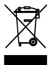
- The European Directive 2002/96/EC relating to Waste Electrical and Electronic Equipment (WEEE) states that household appliances should not be disposed of using the normal solid urban waste cycle. Exhausted appliances should be collected separately in order to optimise the cost of re-using and recycling the materials inside the machine, while preventing potential damage to the atmosphere and to public health. The crossed-out dustbin is marked on all products to remind the owner of their obligations regarding separated waste collection.
For further information relating to the correct disposal of exhausted household appliances, owners may contact the public service provided or their local dealer.
Switching the appliance off
Disconnect your appliance from the electricity supply before carrying out any work on it.
Cleaning the appliance
! Do not use abrasive or corrosive detergents (for example, products in spray cans for cleaning barbecues and ovens), stain removers, anti-rust products, powder detergents or sponges with abrasive surfaces: these may scratch the surface beyond repair.
! Never use steam cleaners or pressure cleaners on the appliance.
- It is usually sufficient simply to wash the hob using a damp sponge and dry it with absorbent kitchen towel.
- If the hob is particularly dirty, rub it with a special glass ceramic cleaning product, then rinse well and dry thoroughly.
- To remove more stubborn dirt, use a suitable scraper. Remove spills as soon as possible, without waiting for the appliance to cool, to avoid residues forming crusty deposits. You can achieve excellent results by using a rust-proof steel wire sponge - specifically designed for glass ceramic surfaces - soaked in soapy water.
- If any plastic or sugary substances are accidentally melted on the hob, remove them immediately with the scraper, while the surface is still hot.
- Once it is clean, the hob may be treated with a special protective maintenance product: the invisible film left by this product protects the surface from drips during cooking. This maintenance task should be carried out while the appliance is warm (not hot) or cold.
- Always remember to rinse the appliance well with clean water and dry it thoroughly: residues can become encrusted during subsequent cooking processes.
Stainless steel frame (only in models with outer frame)
Stainless steel can be marked by hard water which has been left on the surface for a long time, or by cleaning products containing phosphorus. After cleaning, it is advisable to rinse the surface well and dry it thoroughly. If water is spilt on the surface, dry it quickly and thoroughly.
! Some hobs have an aluminium frame which is similar to stainless steel. Do not use any cleaning or degreasing products which are not suitable for use with aluminium.
Disassembling the hob
If it is necessary to disassemble the hob:
- Loosen the screws fixing the alignment springs on each side.
- Loosen the screws holding the fixing hooks in each corner.
- Take the hob out of its installation cavity.
! Do not attempt to repair the appliance yourself. If the appliance breaks down, contact a Service Centre.
Practical advice on using the appliance
In addition, to obtain the best results from your hob:
- Use pans with a thick, flat base in order to fully utilise the cooking zone.
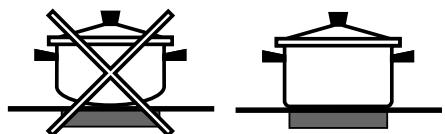
- Always use pans with a diameter which is large enough to cover the hotplate fully, in order to use all the available heat.
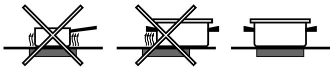
- Make sure that the base of the cookware is always clean and dry, in order to fully utilise and extend the life of both the cooking zones and the cookware.
- Avoid using the same cookware which has been used on gas burners: the heat concentration on gas burners may distort the base of the pan, causing it not to adhere correctly.
Technical description of the models
GB
This table provides a model-by-model list of the energy absorption values, type of heating elements and diameters of each cooking zone.
| Hobs | VRM 641 D X VRM 641 D CVRM 641 MD IX VRM 641 MD C | VEM 645 C | ||
| Cooking zone | Power (W) | Diameter (mm) | Power (W) | Diameter (mm) |
| Back Left | HD 2200/1000 | 210/140 | A 2200 | 210 |
| Back Right | H 1400 | 160 | H 1400 | 160 |
| Front Left | H 1200 | 145 | H 1200 | 145 |
| Front Right | H 1800 | 180 | H 1800 | 180 |
| Total power | 6600 | 6600 | ||
| Hobs | VRM 640 X VRM 640 CVRM 640 VRM 640 M IXVRM 640 M C | VRM 630 CVRM 630 M C | ||
| Cooking zone | Power (W) | Diameter (mm) | Power (W) | Diameter (mm) |
| Back Left | H 1800 | 180 | H 2300 | 210 |
| Back Right | H 1400 | 160 | H 1400 | 160 |
| Front Left | H 1200 | 145 | ||
| Front Right | H 1800 | 180 | H 1800 | 180 |
| Total power | 6200 | 5500 | ||
Key:
H = single hilight
HD = double highlight
A = single halogen

Italian, 1

French, 9

English, 17

German, 25

Spanish, 33

Portuguese, 41

Polish, 49

H = individual highlight
HD = double highlight
A = individual halogen

Italian, 1

French, 9

English, 17

German, 25

Spanish, 33

Portuguese, 41

Polish, 49

REVERSED HEATING PLATE
- POSITIONING
- BUILT-IN APPLIANCE
- VENTILATION
- FIXING
- ELECTRICAL CONNECTION
- TERMINAL BOARD
- SINGLE-PHASE CONNECTION
- OTHER TYPES OF CONNECTION
- CONNECTING THE ELECTRICITY SUPPLY CABLE TO THE MAINS
- THE MANUFACTURER DECLINES ANY LIABILITY SHOULD THESE SAFETY MEASURES NOT BE OBSERVED
- SWITCHING ON THE GLASS CERAMIC HOB
- TRADITIONAL COOKING ZONES
- EXTENDABLE COOKING ZONES
- OPERATION INDICATOR LIGHT (C)
- RESIDUAL HEAT INDICATOR LIGHT (E)
- GENERAL SAFETY
- DISPOSAL
- SWITCHING THE APPLIANCE OFF
- CLEANING THE APPLIANCE
- DISASSEMBLING THE HOB
- PRACTICAL ADVICE ON USING THE APPLIANCE
- TECHNICAL DESCRIPTION OF THE MODELS
- KEY
Brand : INDESIT
Model : VRM640C
Category : Refrigerator