
700-00041 - Surveillance Camera Adj - Free user manual and instructions
Find the device manual for free 700-00041 Adj in PDF.


| Product Type | Network Bullet Camera |
| Brand | Adj |
| Model | 700-00041 (also compatible with 700-00040, 700-00046, 700-00055) |
| Power Supply | AC 24V or DC 12V (SELV and Limited Power Source) |
| Adjustment Range | Pan: 0° to 360°, Tilt: 0° to 90°, Rotation: 0° to 360° |
| Operating Temperature | -30°C to +60°C |
| Mounting Type | Ceiling mount (wall mount possible) |
| Installation Accessories | Drill template and expansion screws included |
| Network Interface | Ethernet (RJ45) |
| Management Software | iVMS-4200 client software |
| Web Browser Support | Internet Explorer 6.0+, Safari 5.02+, Firefox 3.5+, Chrome 8+ |
| Operating System Requirements | Windows XP SP1+, Vista, Win7, Server 2003/2008 32-bit |
| CPU Requirement | Intel Pentium IV 3.0 GHz or higher |
| RAM Requirement | 1 GB or higher |
| Display Resolution | 1024x768 or higher |
| Compliance | FCC Part 15, CE (LVD, EMC, RoHS), WEEE, Battery Directive |
| Safety Certification | UL60950-1 tested for fire, shock, casualty hazards |
| Protection Features | Do not expose to laser beam; avoid extreme temperatures and humidity |
| CMOS Cleaning | Use clean cloth with ethanol; avoid touching with fingers |
| Adjustable Bracket | Yes (3-axis) |
| Sun Shield | Yes (included) |
| Back Box | Yes |
| Grounding Screw | Yes |
| Reset Button | Yes |
Frequently Asked Questions - 700-00041 Adj
User questions about 700-00041 Adj
0 question about this device. Answer the ones you know or ask your own.
Ask a new question about this device
Download the instructions for your Surveillance Camera in PDF format for free! Find your manual 700-00041 - Adj and take your electronic device back in hand. On this page are published all the documents necessary for the use of your device. 700-00041 by Adj.
USER MANUAL 700-00041 Adj
computer, peripherals
and security
Network Bullet Camera
700-00040
700-00041
700-00046
700-00055
Guida rapida
Figure 1-1 Bullet Camera Overview
Table 1-1 Description
natural_image
Technical line drawing of a mechanical component with screws and a side panel (no text or symbols)Figure 2-2 Secure the Camera to the Ceiling
Figure 2-3 3-axis Adjustment
flowchart
graph LR
    A["Network Camera"] -->|Network cable| B["Switch"]
    B -->|Network cable| C["Computer"]
Figure 3-1 Wiring over LAN
Figure 3-3 Modify Network Parameters
Display: 1024×768 resolution or higher
Web Browser: Internet Explorer 6.0 and above version, Apple Safari 5.02 and above version, Mozilla Firefox 3.5 and above version and Google Chrome8 and above version
Passaggi:
Figure 4-2 Download Plug-in
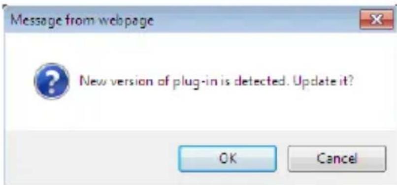
Figure 4-3 Download Plug-in
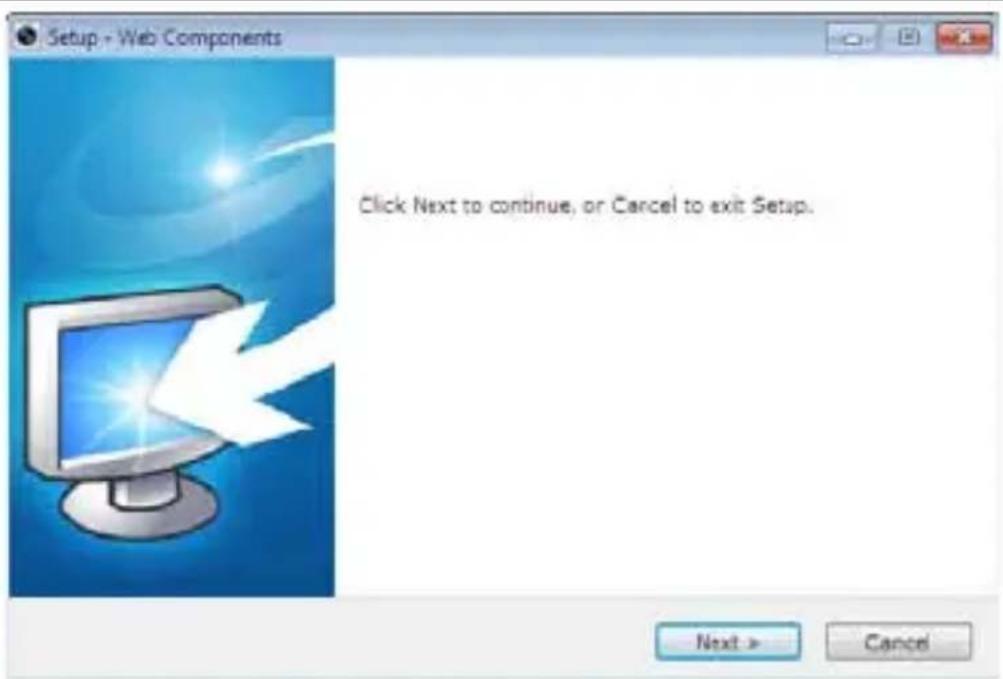
Figure 4-4 Install Plug-in
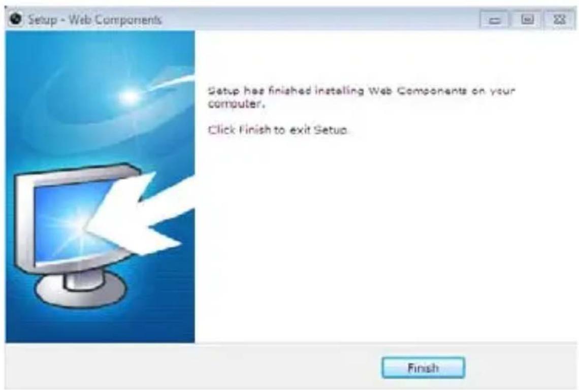
Figure 4-5 Install Plug-in
computer, peripherals
and security
Network Bullet Camera
700-00040
700-00041
700-00046
700-00055
Quick Operation Guide
Thank you for purchasing our product. If there are any questions, or requests, please do not hesitate to contact the dealer.
About This Manual:
This manual applies to 700-00040,700-00041, 700-00046, 700-00055 bullet camera.
This manual may contain several technical incorrect places or printing errors, and the content is subject to change without notice. The updates will be added to the new version of this manual. We will readily improve or update the products or procedures described in the manual.
DISCLAIMER STATEMENT
"Underwriters Laboratories Inc. ("UL") has not tested the performance or reliability of the security or signaling aspects of this product. UL has only tested for fire, shock or casualty hazards as outlined in UL's Standard(s) for Safety, UL60950-1. UL Certification does not cover the performance or reliability of the security or signaling aspects of this product. UL MAKES NO REPRESENTATIONS, WARRANTIES OR CERTIFICATIONS WHATSOEVER REGARDING THE PERFORMANCE OR RELIABILITY OF ANY SECURITY OR SIGNALING RELATED FUNCTIONS OF THIS PRODUCT.
Regulatory Information
FCC Information
FCC compliance: This equipment has been tested and found to comply with the limits for a digital device, pursuant to part 15 of the FCC Rules. These limits are designed to provide reasonable protection against harmful interference when the equipment is operated in a commercial environment. This equipment generates, uses, and can radiate radio frequency energy and, if not installed and used in accordance with the instruction manual, may cause harmful interference to radio communications. Operation of this equipment in a residential area is likely to cause harmful interference in which case the user will be required to correct the interference at his own expense.
FCC Conditions
This device complies with part 15 of the FCC Rules. Operation is subject to the following two conditions:
- This device may not cause harmful interference.
- This device must accept any interference received, including interference that may cause undesired operation.
EU Conformity Statement

This product and - if applicable - the supplied accessories too are marked with "CE" and comply therefore with the applicable harmonized European standards listed under the
Low Voltage Directive 2006/95/EC, the EMC Directive 2004/108/EC, the RoHS Directive 2011/65/EU.
natural_image
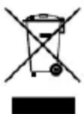
Symbol of a trash bin with crossed lines indicating no waste or discharge (no text or labels)2012/19/EU (WEEE directive): Products marked with this symbol cannot be disposed of as unsorted municipal waste in
the European Union. For proper recycling, return this product to your local supplier upon the purchase of equivalent new equipment, or dispose of it at designated collection points. For more information see: www.recyclethis.info.

2006/66/EC (battery directive): This product contains a battery that cannot be disposed of as unsorted municipal waste in the European Union. See the product documentation for specific battery information. The battery is marked with this symbol, which may include lettering to indicate cadmium (Cd), lead (Pb), or mercury (Hg). For proper recycling, return the battery to your supplier or to a designated collection point. For more information see: www.recyclethis.info
Safety Instruction
These instructions are intended to ensure that user can use the product correctly to avoid danger or property loss.
The precaution measure is divided into "Warnings" and "Cautions"
Warnings: Serious injury or death may occur if any of the warnings are neglected.
Cautions: Injury or equipment damage may occur if any of the cautions are neglected.
 |  |
| Warnings Follow these safeguards to prevent serious injury or death. | Cautions Follow these precautions to prevent potential injury or material damage. |

Warnings
In the use of the product, you must be in strict compliance with the electrical safety regulations of the nation and region.
Please refer to technical specifications for detailed information.
Input voltage should meet both the SELV(Safety Extra Low Voltage) and the Limited Power Source with AC 24V or DC 12V according to the IEC60950-1 standard. Please refer to technical specifications for detailed information.
Do not connect several devices to one power adapter as adapter overload may cause over-heating or a fire hazard.
Please make sure that the plug is firmly connected to the power socket.
When the product is mounted on wall or ceiling, the device shall be firmly fixed.
If smoke, odor or noise rise from the device, turn off the power at once and unplug the power cable, and then please contact the service center.
If the product does not work properly, please contact your dealer or the nearest service center. Never attempt to disassemble the camera yourself. (We shall not assume any responsibility for problems caused by unauthorized repair or maintenance.)

Cautions
Make sure the power supply voltage is correct before using the camera.
Do not drop the camera or subject it to physical shock.
Do not touch CMOS modules with fingers. If cleaning is necessary, use clean cloth with a bit of ethanol and wipe it gently. If the camera will not be used for an extended period, please replace the lens cap to protect the CMOS from dirt.
Do not aim the camera at the sun or extra bright places. Blooming or smearing may occur otherwise (which is not a malfunction), and affect the endurance of CMOS at the same time.
The CMOS may be burned out by a laser beam, so when any laser equipment is in using, make sure that the surface of CMOS will not be exposed to the laser beam.
Do not place the camera in extremely hot, cold (the operating temperature shall be-30°C\~+60°C), dusty or damp locations, and do not expose it to high electromagnetic radiation.
To avoid heat accumulation, good ventilation is required for operating environment.
Keep the camera away from liquid while in use.
While in delivery, the camera shall be packed in its original packing, or packing of the same texture.
Regular part replacement: a few parts (e.g. electrolytic capacitor) of the equipment shall be replaced regularly according to their average enduring time. The average time varies because of differences between operating environment and using history, so regular checking is recommended for all the users. Please contact with your dealer for more details.
Improper use or replacement of the battery may result in hazard of explosion. Replace with the same or equivalent type only. Dispose of used batteries according to the instructions provided by the battery manufacturer.
1 Overview
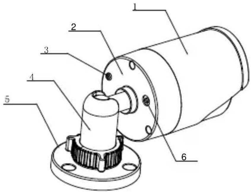
Figure 1-1 Bullet Camera Overview
Table 1-1 Description
| No. Description | |
| 1 Sun Shield | |
| 2 Back Box | |
| 3 Grounding Screw | |
| 4 Adjustable Bracket | |
| 5 Mounting Base | |
| 6 Reset |
2 Installation
Before you start:
- Please make sure that the device in the package is in good condition and all the assembly parts are included.
● Make sure that all the related equipment is power-off during the installation. - Check the specification of the products for the installation environment.
● Make sure the power supply is matched with your required voltage to avoid damage. - If the product does not function properly, please contact your dealer or the nearest service center. Do not disassemble the camera for repair or maintenance by yourself.
- Please make sure that the wall is strong enough to withstand three times the weight of the camera.
Steps:
- Attach the drill template on the wall.
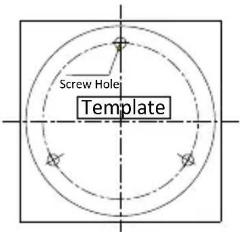
Figure 2-1 Attach the template
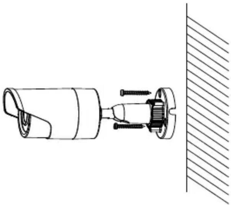
- Secure the camera to the ceiling with the supplied expansion screws.
natural_image
Technical line drawing of a mechanical assembly with screws and a side panel (no text or symbols)Figure 2-2 Secure the Camera to the Ceiling
- Adjust the Lens
1). Loosen the adjustable nut on the bracket.
2). Adjust the panning angle [0\~360°] of the camera.
3). Adjust the tilting angle [0 90^] of the camera.
4). Rotate 0\~360° to adjust azimuth angle of the image.
5). Tighten the adjustable nut to complete the installation.
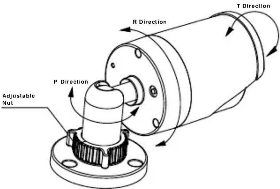
Figure 2-3 3-axis Adjustment
3 Setting the Network Camera over the LAN
Purpose:
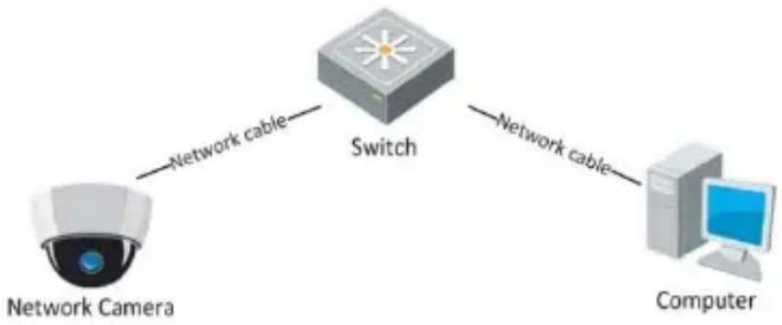
To view and configure the camera via LAN (Local Area Network), you need to connect the network camera in the same subnet with your PC. Then install the iVMS-4200 software to search and change the IP address of the network camera. The following figure shows the cable connection of a network camera and a PC:
flowchart
graph LR
    A["Network Camera"] -->|Network cable| B["Switch"]
    B -->|Network cable| C["Computer"]
Figure 3-1 Wiring over LAN
Set the IP address of the camera for accessing via LAN.
Steps:
- Use iVMS-4200 client software to detect the online devices. Please refer to the user manual of iVMS-4200 client software for detailed information.
- Search online devices automatically
After launch iVMS-4200 software, it automatically searches the online devices every 15 seconds from the subnet where your computer locates. It displays
the total number and information of the searched devices in the Online Devices interface.
Go to Device Management, and click Server tab on the left-top of the window, and you can see the online devices listed on the right bottom of the window.
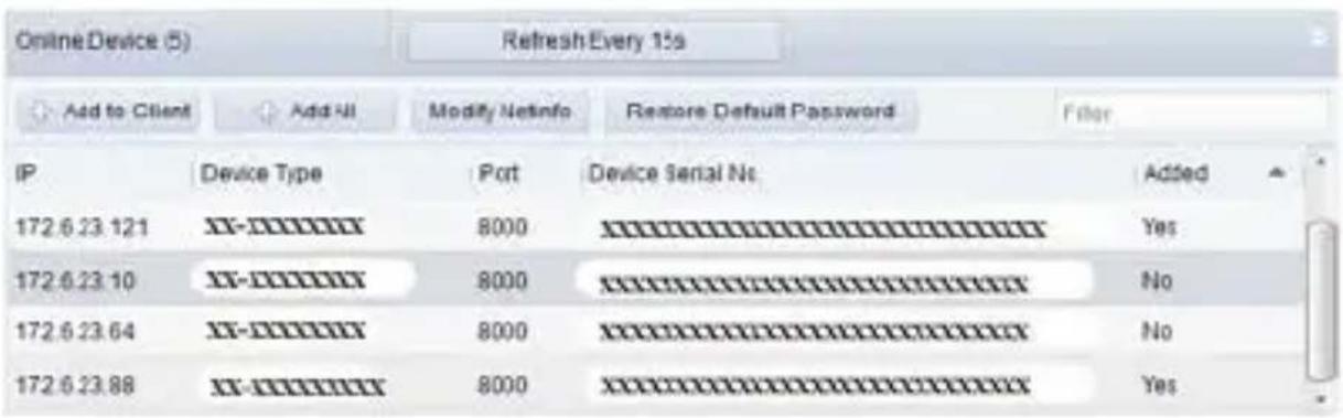
Figure 3-2 Search Online Devices
Device can be searched and displayed in the list in 15 seconds after it went online; it will be removed from the list in 45 seconds after it went offline.
- Search online devices manually
You can also click to refresh the online device list
manually. The newly searched devices will be added to the online list.
- Change the IP address and subnet mask to the same subnet as of your PC.
Steps:
1). Click the device to be modified in the device list and click to modify the network parameters.
Modify Netinfo
2). Edit the modifiable network parameters, e.g. IP address and port number.
3). Enter the admin password in the Manager Password field and click to save the changes.
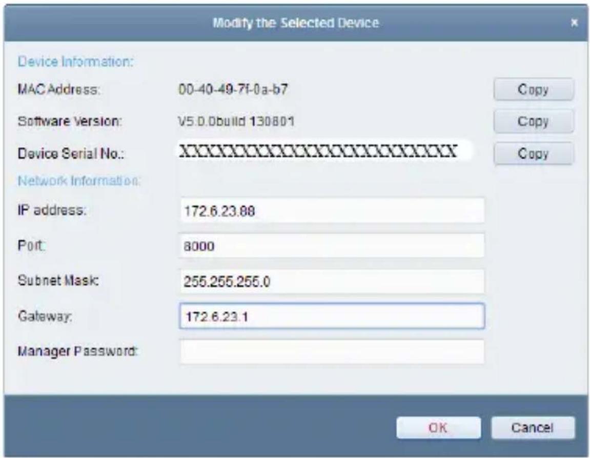
Figure 3-3 Modify Network Parameters

- The default value of the IP address is “192.0.0.64”. The default user name is “admin”, and password is “12345”.
- For accessing the network camera from different subnets, please set the gateway for the network camera after you log in.
4 Accessing via Web Browser
System Requirement:
Operating System: Microsoft Windows XP SP1 and above version / Vista / Win7 /
Server 2003 / Server 2008 32bits
CPU: Intel Pentium IV 3.0 GHz or higher
RAM: 1G or higher
Display: 1024×768 resolution or higher
Web Browser: Internet Explorer 6.0 and above version, Apple Safari 5.02 and above version, Mozilla Firefox 3.5 and above version and Google Chrome8 and above version
Steps:
- Open the web browser.
- In the browser address bar, input the IP address of the network camera, e.g., 192.0.0.64 and hit the enter key to enter the login interface.
-
Input the user name and password.
-
Click

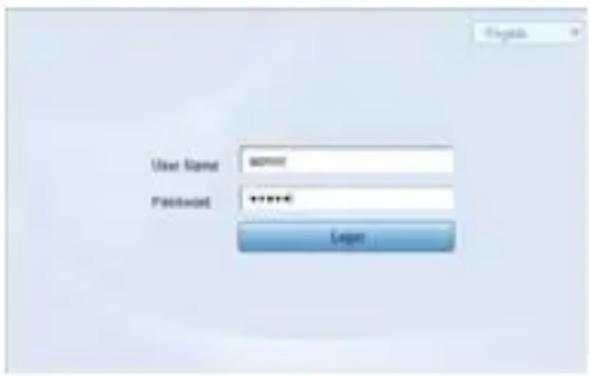
Figure 4-1 Login Interface
- Install the plug-in before viewing the live video and managing the camera. Please follow the installation prompts to install the plug-in.
You may have to close the web browser to finish the installation of the plug-in.
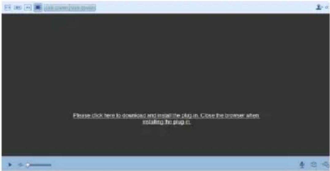
Figure 4-2 Download Plug-in

Figure 4-3 Download Plug-in
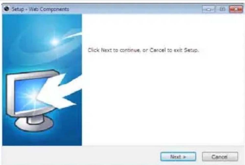
Figure 4-4 Install Plug-in
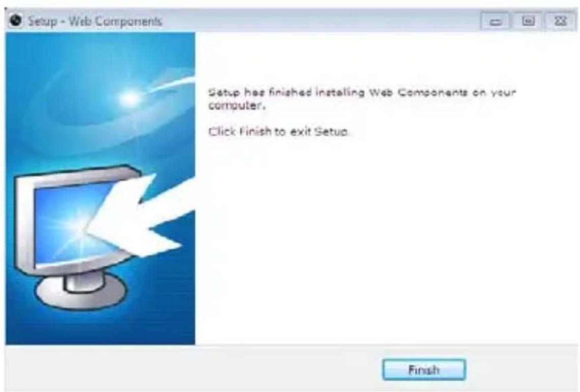
Figure 4-5 Install Plug-in
- Reopen the web browser after the installation of the plug-in and repeat the above steps 2-4 to login.
For detailed instructions of further configuration, please refer to the user manual of network camera.
SCOPRI L'INTERO MONDO ADJ
natural_image
Black CRT computer tower with keyboard and mouse, no visible text or symbols on the device body
natural_image
White ADJ mobile phone with circular dial and antenna (no visible text or symbols)
natural_image
Hand interacting with a touchscreen display showing a '155' button, next to a black hardcover (no text or symbols on the device)
natural_image
Close-up of a hand holding a small object, with a camera lens visible in the background (no text or symbols)VIENI A TROVARCI SU

www.adj.it
for Benelux: www.adjbenelux.com

- Network Bullet Camera
- Passaggi:
- About This Manual:
- DISCLAIMER STATEMENT
- Regulatory Information
- FCC Information
- FCC Conditions
- EU Conformity Statement
- Safety Instruction
- Warnings
- Cautions
- Overview
- Installation
- Before you start:
- Steps:
- Setting the Network Camera over the LAN
- Purpose:
- Set the IP address of the camera for accessing via LAN.
- - Search online devices manually
- Accessing via Web Browser
- System Requirement:
- SCOPRI L'INTERO MONDO ADJ
- VIENI A TROVARCI SU
Brand : Adj
Model : 700-00041
Category : Surveillance Camera