
REG Sentry Access Control - Access Control System BOSCH - Free user manual and instructions
Find the device manual for free REG Sentry Access Control BOSCH in PDF.


| Product Type | Access Control System |
| Brand | Bosch |
| Model | REG Sentry |
| Dimensions (Approx.) | 300 x 200 x 100 mm |
| Weight (Approx.) | 2 kg |
| Power Supply | 12V DC, 1A |
| Supported Credentials | Proximity cards, PIN codes |
| Number of Users | Up to 1000 |
| Number of Doors | 1 (expandable) |
| Communication | Wiegand, RS-485 |
| Operating Temperature | 0°C to 50°C |
| Main Functions | Door lock control, event logging, time schedules |
| Maintenance | Clean with a dry, soft cloth; avoid liquids |
| Safety Features | Tamper switch, anti-passback support |
| Spare Parts & Repairability | Replacement parts available from Bosch service centers |
| General Information | Designed for small to medium businesses; indoor use |
Frequently Asked Questions - REG Sentry Access Control BOSCH
User questions about REG Sentry Access Control BOSCH
0 question about this device. Answer the ones you know or ask your own.
Ask a new question about this device
Download the instructions for your Access Control System in PDF format for free! Find your manual REG Sentry Access Control - BOSCH and take your electronic device back in hand. On this page are published all the documents necessary for the use of your device. REG Sentry Access Control by BOSCH.
USER MANUAL REG Sentry Access Control BOSCH
Licence Plate Recognition System
Installation and Instruction Manual
Reg-Sentry
The following instructions assume a good working knowledge of the windows operating system. If you are networking this unit, it is assumed that you have a good working knowledge of network systems. If either of these assumptions are incorrect it advised that you consult an expert before attempting to install and commission the Reg-Sentry unit.
Licence Plate Recognition Access Control System
(REG-SENTRY)
Installation Instructions
Contents Page
Description....3
Installation....3
Camera Installation....3
Camera Positioning....3
Reg-Sentry Installation....4
Wall Mounting....4
Cable Connection....5
Commissioning 7
Trouble Shooting....11
Network Setting 11
Return to Default Setting 14
LED Location and Function 15
Figure 1 Camera view angles ok....3
Figure 2 Camera view angles too big....3
Figure 3:Mounting Hole Positions....4
Figure 4: Stand Alone Configuration....5
Figure 5: Sentry ID Text Box....7
Figure 6: Password Box....8
Figure 7: Live Stream Function....8
Figure 8:Settings Window....9
Figure 9: Black/White List ....10
Figure 10: License Plate Removal ....10
Figure 11: Network Connection....11
Figure 12: Local Area Connection Properties ....11
Figure 13: Internet Protocol (TCP/IP) Properties ......12
Figure 14: Reg-Sentry Web Service Logon Page 12
Figure 15:System Information Hyperlink....13
Figure 16: Change Network Settings Hyperlink 13
Figure 17: Network Setting Page ....14
Figure 18: Link Connection J8....14
Figure 19: LED Location ....15
Figure 20: SentryViewer Interface Help Document....16
Figure 21: Settings Menu Help Document ....17
Description
The Reg-Sentry is a self contained access controller that uses automatic licence plate recognition (ALPR). It requires a single video input (we recommend only using a Bosch security systems ALPR camera) and provides a switched relay output (NO/COM/NC) that can be utilised for access control. The switched output operates in conjunction with a user definable black/white list that is downloadable to the Reg-Sentry via an ethernet (TCP/IP) connection.
Installation
The REG-SENTRY will accept an input supply of 12V-24V AC or DC and is supplied with 4m of power cable already fitted. The input current at 24Vdc is typical 0.15A (3.6W). The recommended rating of a 12Vdc power supply is 0.34A minimum (4.1W).
The operating temperature range for the unit is -40^ to +50^ .
Camera Installation
Please refer to the installation manual for the ALPR camera unit
Camera Positioning
The camera should be mounted in such a way that in the resulting image of a single line license plate a horizontal line can be drawn which crosses both the left edge and the right edge of the license plate.
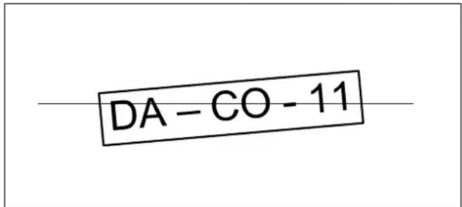
Figure 1 Camera view angles ok

Figure 2 Camera view angles too big
Mount the camera in such way that an ideal image of the license plate is captured when the license plate is in the centre of in the recorded image. The camera should be focussed on the spot where the incoming vehicle is likely to stop. It is advantageous to mark this area with a stop sign e.t.c. so that you can ensure a good image of the vehicles licence plate.
NB The capture software requires that the license plate should take up from 25 to 33% of the image horizontally. The licence plate should be situated at the specified operating distance of the attached ALPR camera, please refer to the manufacturer's installation manual.
The maximum vertical view angle of an ALPR camera is 30 degrees.

The maximum horizontal view angle of an ALPR camera is 25 degrees.
In most systems the horizontal angle and vertical angles are somewhere between 15 and 20 degrees.
Avoid possible blocking objects in the view path of the camera such as (moveable) bars.
Reg-Sentry Installation
Wall Mounting
The REG-SENTRY is supplied in a polycarbonate box, with 4.5mm fixing holes in the base, these can be accessed by removing the lid of the unit. The mounting holes are located directly below the lid screw mounting holes. The mounting holes are 113.5mm apart along the width of the base and 163.5mm apart along the length of the base. See fig 1.

Figure 3:Mounting Hole Positions
Cable Connection

Figure 4: Stand Alone Configuration
There are five cable glands present on the Reg-Sentry (see fig 4). These glands will accommodate cables with an external diameter of 3mm to 6.5mm.
Video Cable (Screw terminal type Reg-Sentry)
At the top of the box is the video cable entry point. A good quality 75Ω video cable should be used between the camera and the Reg-Sentry.
1) Feed the cable into the top of the sentry unit through the cable gland.
2) Strip back the video cable sheath by no more than 10mm (see fig 4).
3) Peel the braid away from the central insulation and twist into a single conductor.
4) Strip back the central Insulation to expose no more than 5mm of conductor (see fig 4).
5) Insert the braid into the screw terminal labelled "GND" that is associated with the "Y" terminal. The central conductor should be inserted into the screw terminal labelled "Y". NB Ensure that the camera is disconnected from its power supply during this operation, and that the video cable screen (braid) is connected before the central conductor.
6) Lock the cable in position using the screw terminals.
7) Tighten the outer nut of the cable gland until a firm seal has been made to the cable.
Video Cable (BNC type Reg-Sentry)
At the top of the box is the video cable entry point. A good quality 75Ω video cable should be used between the camera and the Reg-Sentry.
1) Feed the cable into the top of the sentry unit through the cable gland.
2) Refer to BNC connector manufacturers instructions on how to attach the BNC to the internal end of the video cable.
3) Connect the BNC connector to the socket provided. NB Ensure that the camera is disconnected from its power supply during this operation.
4) Tighten the outer nut of the cable gland until a firm seal has been made to the cable.
Relay Cable
A 3 core cable will be required to access the relay outputs (for installation to the barrier), normally closed (NC), Common (COM) and normally open (NO).
1) Feed the cable into the cable gland at the bottom of the Reg-Sentry (see fig 4).
2) Strip the cable sheath to expose no more than 20mm of the 3 internal cables.
3) Strip the internal cables to expose no more than 5mm of conductor.
4) Insert the cables into the NC/COM/NO screw terminals and lock down.
5) Tighten the outer nut of the cable gland until a firm seal has been made to the cable.
The relay outputs will need to be connected to the control mechanism of the barrier / Gate to be controlled. You will need to refer to the manufacturer's installation manual. The relay is rated at 30W with a maximum operating voltage of 125 VAC and 110VDC.
Power Cable
A 4mm power cable is already provided. This will accept both AC and DC inputs from 12 to 24 volts. The input current at 24Vdc is typical 0.15A (3.6W). The recommended rating of a 12Vdc power supply is 0.34A minimum (4.1W).
Network Connection
A network connection is required to commission the Reg-Sentry. This can either be from a standalone PC/Laptop (i.e. an adhoc connection) or a networked system. A standard network cable (Cat 5e) will be adequate for either situation.
A cable gland has been provided should you wish to hardwire the unit to your network, however you will need to crimp an RJ45 connector internally to the Reg-Sentry to do this as the RJ45 connector will not pass through the cable gland.
Commissioning
To commission the Reg-Sentry you will need to connect the unit to a PC using the network connector on the p.c.b. Use a standard network cable (Cat 5e) to make this connection.
The following instructions assume a good working knowledge of the windows operating system. If you are networking this unit, it is assumed that you have a good working knowledge of network systems. If either of these assumptions are incorrect, it advised that you consult an expert before attempting to commission the Reg-Sentry unit.
The Reg-Sentry uses a TCP/IP interface which is DHCP enabled. If a DHCP server is not detected the Reg-Sentry unit will default to a static IP address of 192.168.0.204.
The Reg-Sentry uses port 50000 for its communications, if you are using a firewall you will need to configure the firewall to allow access to port 50000 and to the SentryViewer program.
1) Install the Sentry Viewer onto your PC/Laptop using the installer package provided on the Reg-Sentry CD.
Alternatively you can copy the "Reg-Sentry Viewer" folder onto your computer (i.e. C:). The "Reg-Sentry Viewer" folder can be found on the Reg-Sentry CD.
2) Attach the Reg-Sentry to the computer using a Cat5e network cable.
3) Apply power to the Reg-Sentry. The "DSP_F" LED will start flashing, wait until this LED stops flashing and is continually lit (the LED is green in colour). N.B. no processing will occur until this LED has stopped flashing.
4) Launch the Sentry Viewer using the executable file "SentryViewer.exe" or desktop icon.
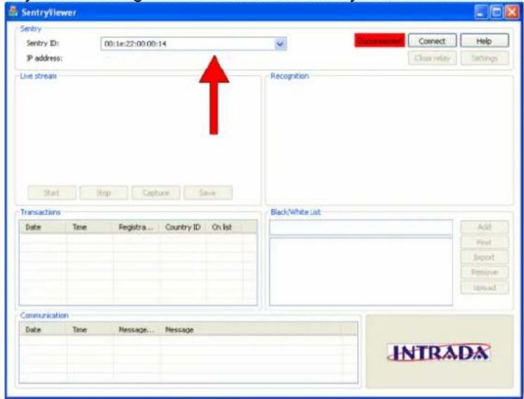
Figure 5: Sentry ID Text Box
5) Enter the IP address assigned to the Reg-Sentry into Sentry ID box. The default IP address when not using a DHCP server is 192.168.0.204. If you are connecting to a DHCP server then you will need to contact your network administrator to obtain the IP address of your device. If you have problems connecting to the Reg-Sentry then refer to the Network settings section of this manual.
6) Once connected, the password box will now appear in front of the viewer. Initially, the password is unset. Clicking on the ok button without entering any text into the box will give you full access to the sentry viewer.

Figure 6: Password Box
7) The Sentry Viewer has a live video stream facility. This live video stream will however slow down the function of the Reg-Sentry significantly and is only provided as an aid to commissioning the unit i.e. for setting up your camera placement to achieve an optimum viewing angle.
The live video stream is activated by clicking on the "Start" button. The blue LED labelled "DSP 2" indicates when the live video stream is active.
The "Stop" button will deactivate the live video stream.
The "Capture" button enables a single frame from the camera to be captured, this can then be stored by clicking on the "Save" button. The resulting JPEG file is stored in a file location that can be set in the settings menu.

Figure 7: Live Stream Function
8) The Settings menu has several functions and is activated by clicking on the "Settings" button, see fig 8. NB Please wait until the window is fully populated before attempting to change any of the settings.
8.1) The name of the sentry unit can be set by entering an appropriate name into the camera name text box
8.2) The onboard date can be set using the dropdown calendar.
8.3) The onboard time can be set using the "time" text box and the up/down arrows
8.4) Security level, this can be set for high, medium and low. The high setting only allows for exact matches to the black/white list. The medium setting will allow for a 1 character difference and the low setting will allow a 2 character difference from the black/white list.
8.5) A variable time period for the relay switch can be set using the "Close Relay Duration" text box.
8.6) Black/White List Type, a white list will close the relay switch for any number plate on the black/white list. A black list will close the relay switch for any number plate not on the black/white list. The Reg-Sentry can only be operated as either a black list or a white list.
8.7) While the Sentry Viewer has an active connection with a Reg-Sentry unit it will copy the transaction list (text only) into a text file. The location of this text file can be specified using the "storage directory" text box. NB Any captured camera frames that are saved will also be saved in this directory.
8.8) While the SentryViewer has an active connection with a Reg-Sentry unit, it can store recognition images to a local hard drive. To activate this function, click on the tickbox, "save recognition images". All images will be saved in the image storage path. The location can be specified using the "image storage path" text box.
8.9) The SentryViewer password can be set by clicking on the "change password" button
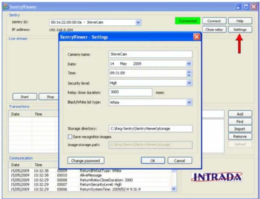
Figure 8: Settings Window
9) The basic function of the Reg-Sentry is to compare captured licence plates with those stored on a list. To enter a single license plate onto the list, enter the text string (i.e. license plate) into the text box labelled "Black / White list".
Click the "ADD" button. This will add the license plate the list displayed on the sentry viewer. To upload the displayed list to the Reg-Sentry, click on the "Upload" button. The entire license plate list is then copied to the Reg-Sentry.
A list of license plates can also be loaded into the Sentry Viewer using an unformatted text file (one license plate per line). Clicking on the "Import" button will open a standard browser that will enable you to locate your text file.
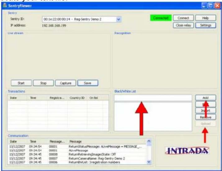
Figure 9: Black/White List
10) To remove a license plate from the list, select the number plate by clicking on it and the click on the remove button. This will remove the license plate from the list on the Sentry Viewer. Click on the "upload" button to copy the list to the Reg-Sentry N.B. You need to upload the list to remove the license plate from the Reg-Sentry.

Figure 10: License Plate Removal
Trouble Shooting
Network Setting
The default Reg-Sentry IP address is 192.168.0.204. It is possible that this IP address will be incompatible with your hardware i.e. it is not within the range of IP addresses that your server or computer will allow. If a non DHCP server is used or the device is connected directly to a PC / Laptop this incompatibility can cause the Reg-Sentry not to communicate with the computer running the Sentry Viewer software.
If this is the case then you will need to alter the network setting of your "Local Area Connection" on your PC or laptop to enable initial access to the Reg-Sentry. This can be done by selecting "My Network places" from the windows start menu and viewing the network connections page.
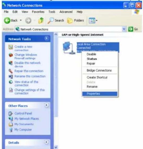
Figure 11: Network Connection
Right click on the relevant local area connection and select properties.

Figure 12: Local Area Connection Properties
Select "Internet Protocol (TCP/IP)" and then click on the "Properties" button.

Figure 13: Internet Protocol (TCP/IP) Properties
Select the "Use the following IP address" option and then enter the following IP address, 192.168.0.200. Enter the subnet mask as 255.255.255.0
N.B. Make a note of any current settings before changing the network settings.
Once the pc network settings have been change you will be able to access the Reg-Sentry by typing 192.168.0.204 into your web browser.

Figure 14: Reg-Sentry Web Service Logon Page
The login password will be the last 4 characters of the Reg-Sentry MAC address. Using the web service provided will enable you to alter the Reg-Sentry's IP address to a suitable value for your system. Once this is done you should revert to your old network settings.
Once you have logged on select the systems information page

ARVOO AC-01

Figure 15:System Information Hyperlink
Follow the change network settings hyperlink

Figure 16: Change Network Settings Hyperlink

Figure 17: Network Setting Page
This page allows all the relevant network setting to be changed.
Return to Default Setting
In the event that your network settings are lost or incorrect, it is possible to return the Reg-Sentry unit to its default setting. NB the Reg-Sentry unit is statically sensitive and antistatic precautions should be observed during the following procedure.
1) Remove the power from the unit and then the lid. Remove the fascia from the unit by unscrewing the four retaining screws.
2) Place a link across pins 9 and 10 of connector J8.
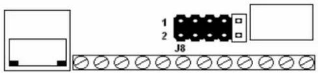
Figure 18: Link Connection J8
3) Return power to the unit, once the unit has rebooted you will be able to access the network settings as described above using the IP address 192.168.0.204.
4) Once you have changed the network settings as required (remember to save them), power down the unit and remove the link from pins 9 and 10 of connector J8.
5) Replace the fascia and lid.
LED Location and Function

Figure 19: LED Location
DSP 1, Lit when a video input is detected. The LED is orange in colour. If this LED is not lit then you should inspect your video cable and ensure that your camera is functioning correctly.
DSP 2, Lit when a live video stream is being provided to the sentry viewer, the LED is blue in colour. During normal operation the live stream should be switched off, you should always ensure that DSP2 is unlit after you have commissioned the unit.
DSP 3, Lit when a recognised number plate is present on the black/white list, the LED is orange in colour.
DSP 4, Lit when a number plate has been processed, the LED is green in colour.
D1, unused
D2, unused
D3, Lit when the relay has been switched. The LED is orange in colour. When this LED is lit the relay is energised and your barrier should operate, if this is not the case inspect all connections from the unit to the barrier control box.
D4, unused
DSP_F, Indicates either a communications fault or a processing fault, this LED will flash continuously when there is no network connection (however the unit should function normally i.e. licence plates are processed). If the Reg-Sentry is not functioning normally (i.e. no licence plates are processed) and this LED is flashing continuously then there is a fault with the unit and you should return the unit for repair. This LED is green in colour.
POWER, this LED will flash briefly if there is a power fault. The LED colour is RED. During normal operation this LED will be unlit. If this LED is lit, inspect all power connections.

Figure 20: SentryViewer Interface Help Document
![SecurityViewer - Settings Camera name: 20 March 2009 Field for specifying the security level of the white/black list matching algorithm in the Sentry. High - Only clear readable license plates are matched with the list (less false reject but a bit of higher chance of false match) Medium - Even license plates not very clearly visible (e.g. due to dir or damaging) are matched with the list (less false reject but a bit of higher chance of false match) Leasy close duration: 3000 msec White Field for specifying the time in milliseconds That the relay of the Sentry stays closed. Black/white list type: White Field for specifying whether the list is used as while list or black list White - The relay of the Sentry is closed when the read license plate is matched with a license on the white list. Black - The relay of the Sentry is closed when the read license plate is not matched with a license plate on the black list. Field for specifying where the list is used as while list or black list White - The relay of the Sentry is closed when the read license plate is matched with a license on the white list. Save recognition images Image storage path: C:\SENTRYIMAGES\ Field for specifying the directory where files generated by the SentryViewer are stored. Close the settings claoq and applies the settings. Open the change password dialog Change Password Open the change password dialog Sett[YIEWER - Change password] X OK Cancel Crosses the claoq without changing the password. Crosses the claoq without changing the password. Old password: New password: Confirm new password: Closest the claoq when the password is changed successfully. The password is stored in the Sentry. Closest the claoq without changing the password. Field for specifying the old password (dots are shown instead of the typed characters) Field for specifying the new password (dots are shown instead of the typed characters) Field for confirming the new password (dots are shown instead of the typed characters) Field for confirming the old password (dots are shown instead of the typed characters) Field for specifying the old password (dots are shown instead of the typed characters) Field for specifying the new password (dots are shown instead of the typed characters) Field for specifying the old password (dots are shown instead of the typed characters)](/content/2026/05/859840/images/8e4e41116620296f5ea681a69bcb4fd95657f941b3710e6c178a9012a776b9bc.jpg)
Figure 21: Settings Menu Help Document
This product complies with
Electromagnetic Compatibility Directive meeting the following standards
EN 61000-6-3: 2001, A11: 2004
EN 50130-4, A1: 1998, A2: 2003
EN55022: 2006 –Class A limits only
FCC:2005 Parts 15.107 & 15.109 –Class A
This equipment has been tested and found to comply with the limits for a class A digital device, pursuant to part 15 of the FCC rules. These limits are designed to provide reasonable protection against harmful interference when the equipment is operated in a commercial environment. This equipment generates, uses and can radiate radio frequency energy and if not installed in accordance with the instruction manual, may cause harmful interference to radio communications.
Operation of this equipment in a residential area is likely to cause interference in which case the user will be required to correct the interference at his/her own expense.
Bosch Security Systems GB Ltd
Derwent House,
Colbourne Crescent,
Nelson Park Ind Est
Cramlington,
Northumberland,
NE23 1WB
England
Tel: +44 (0) 1670 730187
Fax: +44 (0) 1670 730188

- Licence Plate Recognition System
- Installation and Instruction Manual
- Reg-Sentry
- Licence Plate Recognition Access Control System
- (REG-SENTRY)
- Installation Instructions
- Contents Page
- Description
- Installation
- Camera Installation
- Camera Positioning
- Reg-Sentry Installation
- Wall Mounting
- Cable Connection
- Video Cable (Screw terminal type Reg-Sentry)
- Video Cable (BNC type Reg-Sentry)
- Relay Cable
- Power Cable
- Network Connection
- Commissioning
- Trouble Shooting
- Network Setting
- Return to Default Setting
- LED Location and Function
Brand : BOSCH
Model : REG Sentry Access Control
Category : Access Control System