
865-M7 (V1.1) - Motherboard ECS - Free user manual and instructions
Find the device manual for free 865-M7 (V1.1) ECS in PDF.


| Product Type | Motherboard |
| Brand | ECS (Elitegroup Computer Systems) |
| Model | 865-M7 (V1.1) |
| Chipset | Intel 865G/865PE |
| Form Factor | ATX |
| Dimensions (W x D) | 305 mm x 244 mm |
| Weight | Approximately 1.0 kg (2.2 lbs) |
| CPU Socket | LGA775 |
| Supported CPUs | Intel Pentium 4, Celeron |
| Memory Type | DDR SDRAM |
| Maximum Memory | 2 GB (2 x DIMM slots) |
| Expansion Slots | 1 x AGP 8x, 3 x PCI |
| Storage Interfaces | 2 x IDE, 2 x SATA |
| USB Ports | 4 x USB 2.0 (back panel), additional via headers |
| Audio | Realtek ALC655 6-channel codec |
| Integrated Graphics | Intel Extreme Graphics 2 (865G only) |
| Power Supply | Standard ATX power supply (20-pin) |
| BIOS | AMI BIOS with support for Plug and Play |
| Operating Systems Supported | Windows 98/ME/2000/XP |
| Maintenance & Cleaning | Use compressed air to remove dust; avoid liquid cleaners. Handle with anti-static precautions. |
| Safety | Follow ESD safety rules; unplug power before servicing. |
| Spare Parts & Repairability | CPU, RAM, and expansion cards are user-replaceable. Onboard components are not user-serviceable. |
| General Information | Designed for Intel Pentium 4 processors; includes integrated LAN and audio. |
Frequently Asked Questions - 865-M7 (V1.1) ECS
User questions about 865-M7 (V1.1) ECS
0 question about this device. Answer the ones you know or ask your own.
Ask a new question about this device
Download the instructions for your Motherboard in PDF format for free! Find your manual 865-M7 (V1.1) - ECS and take your electronic device back in hand. On this page are published all the documents necessary for the use of your device. 865-M7 (V1.1) by ECS.
USER MANUAL 865-M7 (V1.1) ECS
The TÜV CERT Certification Body for QM Systems of RWTÜV Systems GmbH
hereby certifies in accordance with TÜV CERT procedure that
ELITEGROUP COMPUTER SYSTEMS CO., LTD. ECS MANUFACTURING (SHENZHEN) CO., LTD. ELITE TECHNOLOGY (SHENZHEN) CO., LTD.
2F, No. 240, Sec. 1, Nel Hu Road, Taipei, Taiwan 114, R.O.C. No. 22, Alley 38, Lane 91, Sec. 1, Nel Hu Road, Taipei, Taiwan 114, R.O.C. No. 20 & No. 26, Free Trade Zone, Shataujiao, Shenzhen City, GuangDong Province, China
has established and applies a quality system for
Design, Manufacturing and Sales of Mainboards, Personal Computers, Notebooks and Peripheral Cards
An audit was performed, Report No. 2.5-1585/2000
Proof has been furnished that the requirements according to
ISO 9001 : 2000 / EN ISO 9001 : 2000 / JIS Q 9001 : 2000 / ANSI/ASQC Q9001 : 2000
are fulfilled. The certificate is valid until 27 January 2007
Certificate Registration No. 04100 2000 1325
The company has been certified since 2000

Essen, 04.03.2004


ISO14001
CERTIFICATE
Certificate NO.: 05-2001-065
We hereby certify that
ECS Manufacturing(Shenzhen) Co., Ltd
by reason of its
Environmental Management System
has been awarded this certificate for
compliance with the standard
ISO14001:1996
The Environmental Management System
applies in the following area:
The manufacture of Mother Board and Peripheral Card and interrelated
management activities of ECS Manufacturing(Shenzhen) Co.,Ltd.
which is located in No.20, Free Trade Zone, Shatuojiao, Shenzhen, P. R. China.
Date of issue: 30th Dec 2001
Date of expiry: 29th Dec 2004
Signed by:

This publication, including all photographs, illustrations and software, is protected under international copyright laws, with all rights reserved. Neither this manual, nor any of the material contained herein, may be reproduced without written consent of the author.
Version 1.0
◆▲○□
The information in this document is subject to change without notice. The manufacturer makes no representations or warranties with respect to the contents hereof and specifically disclaims any implied warranties of merchantability or fitness for any particular purpose. The manufacturer reserves the right to revise this publication and to make changes from time to time in the content hereof without obligation of the manufacturer to notify any person of such revision or changes.
*]***○***□■
Microsoft, MS-DOS and Windows are registered trademarks of Microsoft Corp.
MMX, Pentium, Pentium-II, Pentium-III, Celeron are registered trademarks of Intel Corporation.
Other product names used in this manual are the properties of their respective owners and are acknowledged.
◆◆◆◆◆◆◆◆◆◆◆◆◆◆◆◆◆◆◆◆◆◆◆◆◆◆◆◆◆◆◆◆◆◆◆◆◆◆◆◆◆◆◆◆◆◆◆◆◆◆◆◆◆◆◆◆◆◆◆◆◆◆◆◆◆◆◆◆◆◆◆◆◆◆◆◆◆◆◆◆◆◆◆◆◆◆◆◆◆◆◆◆◆◆◆◆◆◆◆◆ ◆ ◆ ◆ ◆ ◆ ◆ ◆ ◆ ◆ ◆ ◆ ◆ ◆ ◆ ◆ ◆ ◆ ◆ ◆ ◆ ◆ ◆ ◆ ◆ ◆ ◆ ◆ ◆ ◆ ◆ ◆ ◆ ◆ ◆ ◆ ◆ ◆ ◆ ◆ ◆ ◆ ◆ ◆ ◆ ◆ ◆ ◆ ◆ ◆ ◆ ◉ ◉ ◉ ◉ ◉ ◉ ◉ ◉ ◉ ◉ ◉ ◉ ◉ ◉ ◉ ◉ ◉ ◉ ◉ ◉ ◉ ◉ ◉ ◉ ◉ ◉ ◉ ◉ ◉ ◉ ◉ ◉ ◉ ◉ ◉ ◉ ◉ ◉ ◉ ◉ ◉ ◉ ◉ ◉ ◉ ◉ ◉ ◉ ◉ ◉ ◎
This equipment has been tested and found to comply with the limits for a Class B digital device, pursuant to Part 15 of the FCC Rules. These limits are designed to provide reasonable protection against harmful interference in a residential installation. This equipment generates, uses, and can radiate radio frequency energy and, if not installed and used in accordance with the instructions, may cause harmful interference to radio communications. However, there is no guarantee that interference will not occur in a particular installation. If this equipment does cause harmful interference to radio or television reception, which can be determined by turning the equipment off and on, the user is encouraged to try to correct the interference by one or more of the following measures:
- Reorient or relocate the receiving antenna.
- Increase the separation between the equipment and the receiver.
- Connect the equipment onto an outlet on a circuit different from that to which the receiver is connected.
- Consult the dealer or an experienced radio/TV technician for help.
Shielded interconnect cables and a shielded AC power cable must be employed with this equipment to ensure compliance with the pertinent RF emission limits governing this device. Changes or modifications not expressly approved by the system's manufacturer could void the user's authority to operate the equipment.
◆◆◆◆◆◆◆◆◆◆◆◆◆◆◆◆◆◆◆◆◆◆◆◆◆◆◆◆◆◆◆◆◆◆◆◆◆◆◆◆◆◆◆◆◆◆◆◆◆◆◆◆◆◆◆◆◆◆◆◆◆◆◆◆◆◆◆◆◆◆◆◆◆◆◆◆◆◆◆◆◆◆◆◆◆◆◆◆◆◆◆◆◆◆◆◆◆◆◆◆ ◊◆◆◆◆◆◆◆◆◆◆◆◆◆◆◆◆◆◆◆◆◆◆◆◆◆◆◆◆◆◆◆◆◆◆◆◆◆◆◆◆◆◆◆◆◆◆◆◆◆◆◆◆◆◆◆◆◆◆◆◆◆◆◆◆◆◆◆◆◆◆◆◆◆◆◆◆◆◆◆◆◆◆◆◆◆◆◆◆◆◆◆◆◆◆◆◆◆◆◆
This device complies with part 15 of the FCC rules. Operation is subject to the following conditions:
- This device may not cause harmful interference, and
- This device must accept any interference received, including interference that may cause undesired operation.
This class B digital apparatus meets all requirements of the Canadian Interference-causing Equipment Regulations.
The manual consists of the following:
Chapter 1
| Introducing the Motherboard | Describes features of the motherboard. |
| Go to ➔ page 1 | |
| Chapter 2 | Describes installation of motherboard components. |
| Installing the Motherboard | Go to ➔ page 7 |
| Chapter 3 | Provides information on using the BIOS Setup Utility. |
| Using BIOS | Go to ➔ page 31 |
| Chapter 4 | Describes the motherboard software |
| Using the Motherboard Software | Go to ➔ page 53 |
Preface i
◆◆◆□▼◆◆
Introducing the Motherboard 1
Introduction....1
Features....2
Motherboard Components....4
÷ 米□▼米□ ✗
Installing the Motherboard 7
Safety Precautions....7
Choosing a Computer Case....7
Installing the Motherboard in a Case....7
Checking Jumper Settings....8
Setting Jumpers....8
Checking Jumper Settings....9
Jumper Settings....9
Connecting Case Components....10
Front Panel Connector....11
Installing Hardware....12
Installing the Processor....12
Installing Memory Modules....14
Installing a Hard Disk Drive/CD-ROM....16
Installing a Floppy Diskette Drive....18
Installing Add-on Cards....19
Dual Monitor Installation (For Windows XP)....23
Dual Monitor Installation (For Windows 2000)....24
Connecting Optional Devices....26
Connecting I/O Devices....29
÷° √⊗ √⊗
Using BIOS 31
About the Setup Utility....31
The Standard Configuration....31
Entering the Setup Utility....31
Updating the BIOS....33
Using BIOS....33
Standard CMOS Features....34
Advanced BIOS Features....36
Advanced Chipset Features....39
Integrated Peripherals....41
Power Management Setup....46
PNP/PCI Configurations....48
PC Health Status....49
Frequency/Voltage Control....50
Load Fail-Safe Defaults....51
Load Optimized Defaults....51
Set Supervisor/User Password....51
Save & Exit Setup Option....51
Exit Without Saving....52
+※□▼□√
X√ X√
Using the Motherboard Software 53
About the Software CD-ROM....53
Auto-installing under Windows 98/ME/2000/XP....53
Running Setup....54
Manual Installation....56
Utility Software Reference....56
Multi-Language Translation
Introduction
Thank you for choosing 865-M7 motherboard of great performance and with enhanced function. 865-M7 motherboard carries a Micro-ATX form factor of 244 x 244 mm. This motherboard is a high performance, enhanced function motherboard that supports LGA775 socket for the latest Intel Pentium 4/Celeron processors for high-end business or personal desktop markets.
The motherboard incorporates the 865GV Northbridge (NB) and ICH5 Southbridge (SB) chipsets. The Northbridge supports a Front Side Bus (FSB) frequency of 800/533MHz using a scalable FSB VCC_CPU. The memory controller supports DDR memory DIMM frequencies of 400/333/266MHz. It supports four DDR SDRAM up to maximum memory of 4GB. DDR Maximum memory bandwidth of 3.2GB/s in single-channel mode (DDR400) and 6.4GB/s in dual-channel mode (DDR400) are supported. One AGP Express slot is used to installed an AGP graphics card that emulates the AGP function.
The ICH5 Southbridge supports three PCI slots which are PCI 2.3 compliant. This motherboard accommodates eight USB 2.0 ports for serial transfers at 480Mb/s (four ports at the rear I/O & two headers onboard). This motherboard complies with AC'97 2.3 CODEC and supports up to six channels of PCM audio output (full AC3 decode). Two onboard IDE connectors support 4 IDE devices in ATA-100/66/33 mode. The Southbridge integrates two Serial ATA host controllers that are SATA v1.0 compliant, supporting two SATA ports with maximum transfer rate up to 150MB/s each. One optional CNR slot allow users to insert CNR cards with Modem and Audio functionality.
There is an advanced full set of I/O ports in the rear panel, including PS/2 mouse and keyboard connectors, COM1, LPT1, VGA port, and four USB ports, one optional 1394a port, one optional LAN port, and audio jacks for microphone, line-in, and line-out. In addition to its excellent performance and stability, the motherboard is highly suited for surfing the Internet and for rich multimedia applications, including streaming video download and are ideal for workstations and high-end home use.
Features
Processor
The 865-M7 uses an LGA775 type of Pentium 4 that carries the following features:
- Accommodates the latest Intel P4/Celeron processors
• Supports a system bus (FSB) of 800/533MHz - Supports "Hyper-Threading" technology CPU
“Hyper-Threading” technology enables the operating system into thinking it’s hooked up to two processors, allowing two threads to be run in parallel, both on separate “logical” processors within the same physical processor.
Chipset
Intel's 865GV (GMCH) Northbridge (NB) and 82801EB (ICH5) Southbridge (SB) chipsets are based on an innovative and scalable architecture with proven reliability and performance.
865GV (NB) • Supports P4/Celeron processors with data transfer rate up to 800/533/400MHz.
• Supports DDR SDRAM at 400/333/266MHz
- AGTL+Host Bus with Integrated Termination Supporting 32-Bits Host Addressing
• 8-bits/66MHz 8X Hub Interface to the Intel 1CH5
- Provides an integrated graphics accelerator delivering cost-effective 3D, 2D and video capabilities.
ICH5 (SB) • Supports up to six PCI Masters fully compliant with PCI 2.3 specification at 33MHz
• Supports 2 channels Ultra ATA 100 bus master IDE controllers
• Supports two Serial ATA Host Controllers
- Compliant with AC'97 v2.3 supporting 6 Channels of audio outputs
• Supports eight USB 2.0 ports for serial transfers at 480Mb/s maximum
Memory
This memory controller can accommodate up to four 2.5V DIMM DDR SDRAM, supporting DDR400/333/266MHz with maximum memory size of 4GB capability.
Audio CODEC
- 16-bit Stereo full-duplex CODEC with 48KHz sampling rate
• Compliant with AC'97 2.3 specifications
• Supports double sampling rate (96KHz) of DVD audio playback
• Support S/PDIF input and output function - Direct Sound 3D TM compatible
Graphics
• 3D setup and render engine
• 2D/3D graphics enhancement
• Video DVD/PV-VCR
• High quality texture engine
• Zone Rendering support
- Video Overlay
Expansion Options
The motherboard comes with the following expansion options:
- Three 32-bit PCI slots
• One AGP Express slot - Two 7-pin SATA connectors
- Two IDE connectors which support four IDE devices
• One floppy disk drive interface
• One optional CNR slot
The motherboard supports Ultra DMA bus mastering with transfer rates of 100/66 33MB/s.
Onboard LAN (optional)
• Supports 10Mb/s and 100Mb/s N-Way Auto-negotiation operation
• Half and Full Duplex
• Supports Wake-on-LAN (WOL) function and remote wake-up
• Supports Full Duplex Flow Control (IEEE 802.3x)
Integrated I/O
The motherboard has a full set of I/O ports and connectors:
- Two PS/2 ports for mouse and keyboard
- One serial port
- One parallel port
- Four USB ports
• One VGA port
• One LAN port (optional)
• One 1394 port (optional)
• Audio jacks for microphone, line-in and line-out
BIOS Firmware
This motherboard uses Award BIOS that enables users to configure many system features including the following:
• Power management
- CPU parameters
• CPU and memory timing
The firmware can also be used to set parameters for different processor clock speeds.

Some hardware specifications and software items are subject to change without prior notice.

Motherboard Components

Table of Motherboard Components
| LABEL | COMPONENT |
| 1 CPU Socket LGA775 socket | for P4/Celcron CPUs |
| 2 CPU_FAN CPU cooling fan | connector |
| 3 DIMM1~DIMM4 184-pin DDR | SDRAM slots |
| 4 IR1 | Onboard infrared header |
| 5 FDD1 Floppy disk drive connector | |
| 6 ATX1 Standard 20-pin ATX | power connector |
| 7 IDE1 Primary IDE connector | |
| 8 IDE2 Secondary IDE connector | |
| 9 SPK1 Speaker header | |
| 10 PWR_FAN Power cooling fan connector | |
| 11 CLR_CMOS Clear CMOS jumper | |
| 12 SATA1~2 | Serial ATA connectors |
| 13 PANEL1 Front panel switch/LED header | |
| 14 BIOS_WP BIOS flash protect jumper | |
| 15 USB3-4 Front Panel USB headers | |
| 16 1394A2* | Onboard 1394a header |
| 17 COM2 | Onboard serial port header |
| 18 CNR1* Communications Networking Riscr slot | |
| 19 SPDIFO1 SPDIF out header | |
| 20 CD_IN Analog audio input connector | |
| 21 PCI1~PCI3 32-bit add-on card slots | |
| 22 JP4 | LAN Enable/Disable jumper |
| 23 AGP1 AGP Express slot | |
| 24 AUDIO1 | Front panel audio header |
| 25 SYS_FAN | Case cooling fan connector |
| 26 ATX12V | 4-pin +12V power connector |
“*” stands for optional components.
This concludes Chapter 1. The next chapter explains how to install the motherboard.
×
★★○□
Safety Precautions
- Follow these safety precautions when installing the motherboard
- Wear a grounding strap attached to a grounded device to avoid damage from static electricity
- Discharge static electricity by touching the metal case of a safely grounded object before working on the motherboard
- Leave components in the static-proof bags they came in
- Hold all circuit boards by the edges. Do not bend circuit boards
Choosing a Computer Case
There are many types of computer cases on the market. The motherboard complies with the specifications for the Micro-ATX system case. First, some features on the motherboard are implemented by cabling connectors on the motherboard to indicators and switches on the system case. Make sure that your case supports all the features required. Secondly, 865-M7 supports one or two floppy diskette drives and four enhanced IDE drives. Make sure that your case has sufficient power and space for all drives that you intend to install.
Most cases have a choice of I/O templates in the rear panel. Make sure that the I/O template in the case matches the I/O ports installed on the rear edge of the motherboard.
This motherboard carries a Micro-ATX form factor of 244 x 244 mm. Choose a case that accommodates this form factor.
Installing the Motherboard in a Case
Refer to the following illustration and instructions for installing the motherboard in a case.
Most system cases have mounting brackets installed in the case, which correspond the holes in the motherboard. Place the motherboard over the mounting brackets and secure the motherboard onto the mounting brackets with screws.
Ensure that your case has an I/O template that supports the I/O ports and expansion slots on your motherboard.
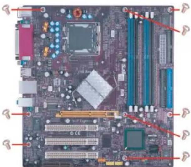

Do not over-tighten the screws as this can stress the motherboard.
Checking Jumper Settings
This section explains how to set jumpers for correct configuration of the motherboard.
Setting Jumpers
Use the motherboard jumpers to set system configuration options. Jumpers with more than one pin are numbered. When setting the jumpers, ensure that the jumper caps are placed on the correct pins.
The illustrations show a 2-pin jumper. When the jumper cap is placed on both pins, the jumper is SHORT. If you remove the jumper cap, or place the jumper cap on just one pin, the jumper is OPEN.
This illustration shows a 3-pin jumper. Pins 1 and 2 are SHORT

SHORT

OPEN

Checking Jumper Settings
The following illustration shows the location of the motherboard jumpers. Pin 1 is labeled.
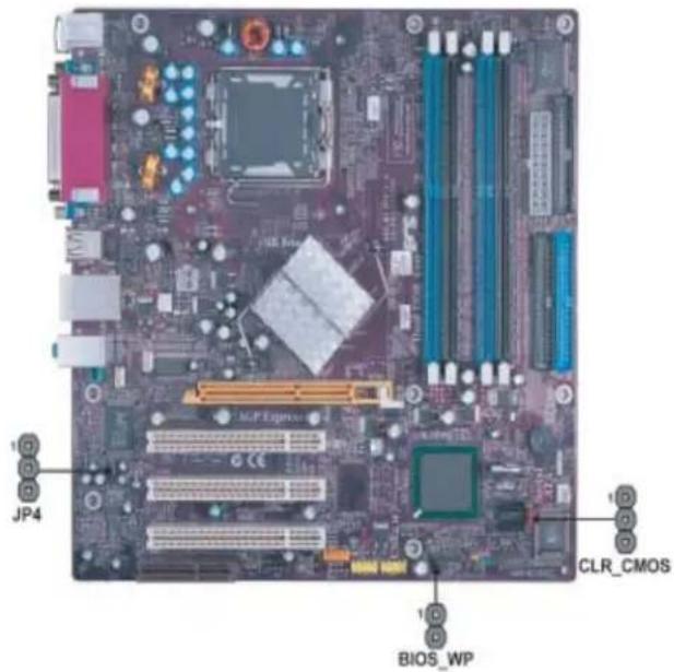
Jumper Settings
| Jumper | Type | Description | Setting (default) | |
| CLR_CMOS | 3-pin | CLEAR CMOS | 1-2: NORMAL2-3: CLEARBefore clearing the CMOS, make sure to turn off the system. | Clear CMOS1(MOC) |
| 2-pinBI | DISPROTECT | OPEN: DISABLESHORT: ENABLE | BIOS_WP1(WNC) | |
| JP4 | 3-pin | LAN FUNCTION | 1-2: ENABLE2-3: DISABLE | JP41(MTS) |
Connecting Case Components
After you have installed the motherboard into a case, you can begin connecting the motherboard components. Refer to the following:
1 Connect the CPU cooling fan cable to CPU_FAN.
2 Connect the case cooling fan connector to SYS_FAN.
3 Connect the power cooling fan connector to PWR_FAN.
3 Connect the case speaker cable to SPK1.
4 Connect the case switches and indicator LEDs to the PANEL1.
5 Connect the standard power supply connector to ATX1.
6 Connect the auxiliary case power supply connector to ATX12V.
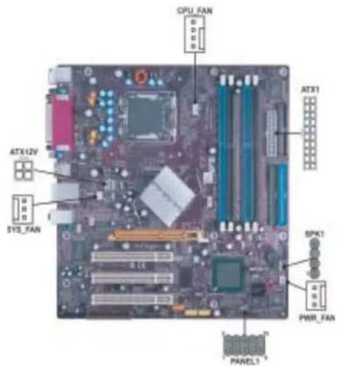
CPUFAN1: FAN Power Connectors
| Pin Signal Name Function | ||
| 1 GND System Ground | ||
| 2 +12V Power +12V | ||
| 3 | Sense | Sensor |
| 4 | PWM | CPU FAN control |

Users please note that the fan connector supports the CPU cooling fan of 1.1A\~2.2A (26.4W max.) at +12V.
SYS FAN/PWR FAN: FAN Power Connectors
| Pin Signal Name Function | |
| 1 GND System Ground | |
| 2 +12V Power +12V | |
| 3 Sense Sensor | |
SPK1: Internal speaker
| Pin Signal Name | |
| 1 Signal | |
| 2 Key | |
| 3 Ground | |
| 4 VCC | |
ATX1: ATX 20-pin Power Connector
| Pin Signal Name Pin Signal Name | |||
| 1 +3.3V 11 +3.3V | |||
| 2 +3.3V 12 -12V | |||
| 3 Ground 13 Ground | |||
| 4 | +5V | 14 | PSON# |
| 5 Ground 15 Ground | |||
| 6 | +5V | 16 | Ground |
| 7 Ground 17 Ground | |||
| 8 | PWRGD | 18 | -5V |
| 9 | +5VSB | 19 | +5V |
| 10 +12V 20 +5V | |||
ATX12V: ATX 12V Power Connector
| Pin Signal Name | |
| 1 | Ground |
| 2 | Ground |
| 3 | +12V |
| 4 | +12V |
Front Panel Header
The front panel header (PANEL1) provides a standard set of switch and LED headers commonly found on ATX or micro-ATX cases. Refer to the table below for information:

| Pin | Signal Name | Function | Pin | Signal Name | Function |
| 1 | HD_LED_P | Hard disk LED(+) | 2 | FP PWR/SLP | *MSG LED(+) |
| 3 | HD_LED_N | Hard disk LED(-) | 4 | FP PWR/SLP | *MSG LED(-) |
| 5 | RST_SW_N | Resct Switch(-) | 6 | PWR_SW_P | Power Switch(+) |
| 7 | RST_SW_P | Resct Switch(+) | 8 | PWR_SW_N | Power Switch(-) |
| 9 | RSVD | Reserved | 10 | Key No pin |
*MSG LED (dual color or single color)
Hard Drive Activity LED
Connecting pins 1 and 3 to a front panel mounted LED provides visual indication that data is being read from or written to the hard drive. For the LED to function properly, an IDE drive should be connected to the onboard IDE interface. The LED will also show activity for devices connected to the SCSI (hard drive activity LED) connector.
Power/Sleep/Message waiting LED
Connecting pins 2 and 4 to a single or dual-color, front panel mounted LED provides power on/off, sleep, and message waiting indication.
Reset Switch
Supporting the reset function requires connecting pin 5 and 7 to a momentary-contact switch that is normally open. When the switch is closed, the board resets and runs POST.
Power Switch
Supporting the power on/off function requires connecting pins 6 and 8 to a momentary-contact switch that is normally open. The switch should maintain contact for at least 50 ms to signal the power supply to switch on or off. The time requirement is due to internal debounce circuitry. After receiving a power on/off signal, at least two seconds elapses before the power supply recognizes another on/off signal.
Installing Hardware
Installing the Processor

Caution: When installing a CPU heatsink and cooling fan make sure that you DO NOT scratch the motherboard or any of the surface-mount resistors with the clip of the cooling fan. If the clip of the cooling fan scrapes across the motherboard, you may cause serious damage to the motherboard or its components.
On most motherboards, there are small surface-mount resistors near the processor socket, which may be damaged if the cooling fan is carelessly installed.
Avoid using cooling fans with sharp edges on the fan casing and the clips. Also, install the cooling fan in a well-lit work area so that you can clearly see the motherboard and processor socket.
Before installing the Processor
This motherboard automatically determines the CPU clock frequency and system bus frequency for the processor. You may be able to change these settings by making changes to jumpers on the motherboard, or changing the settings in the system Setup Utility. We strongly recommend that you do not over-clock processors or other components to run faster than their rated speed.

Warning: Over-clocking components can adversely affect the reliability of the system and introduce errors into your system. Over-clocking can permanently damage the motherboard by generating excess heat in components that are run beyond the rated limits.
This motherboard has an LGA775 processor socket. When choosing a processor, consider the performance requirements of the system. Performance is based on the processor design, the clock speed and system bus frequency of the processor, and the quantity of internal cache memory and external cache memory.
CPU Installation Procedure
The following illustration shows CPU installation components.
A. Unload the cap
- Use thumb & forefinger to hold the lifting tab of the cap.
- Lift the cap up and remove the cap completely from the socket.
B. Open the load plate
- Use thumb & forefinger to hold the hook of the lever, pushing down and pulling aside unlock it.
- Lift up the lever.
- Use thumb to open the load plate. Be careful not to touch the contacts.
C. Install the CPU on the socket
- Orientate CPU package to the socket. Make sure you match triangle marker to pin 1 location.
D. Close the load plate
- Slightly push down the load plate onto the tongue side, and hook the lever.
- CPU is locked completely.
E. Apply thermal grease on top of the CPU.
F. Fasten the cooling fan supporting base onto the CPU socket on the motherboard.
G. Make sure the CPU fan is plugged to the CPU fan connector. Please refer to the CPU cooling fan user's manual for more detail installation procedure.
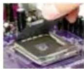
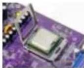
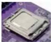


To achieve better airflow rates and heat dissipation, we suggest that you use a high quality fan with 3800 rpm at least. CPU fan and heatsink installation procedures may vary with the type of CPU fan/heatsink supplied. The form and size of fan/heatsink may also vary.
Installing Memory Modules
865-M7 accommodates four 184-pin 2.5V unbuffered Double Data Rate (DDR) SDRAM (Synchronous Dynamic Random Access Memory) memory modules, and supports up to DDR400/333/266. Each module can be installed with 1GB of memory, the total maximum memory size is 4GB.
DDR SDRAM memory module table
| Memory module Memory Bus | |
| DDR266 | 133MHz |
| DDR333 | 166MHz |
| DDR400 | 200MHz |

Do not remove any memory module from its antistatic packaging until you are ready to install it on the motherboard. Handle the modules only by their edges. Do not touch the components or metal parts. Always wear a grounding strap when you handle the modules.
Installation Procedure
Refer to the following to install the memory modules.
1 This motherboard supports unbuffered DDR SDRAM only.
2 Push the latches on each side of the DIMM slot down.
3 Align the memory module with the slot. The DIMM slots are keyed with notches and the DIMMs are keyed with cutouts so that they can only be installed correctly.
4 Check that the cutouts on the DIMM module edge connector match the notches in the DIMM slot.
5 Install the DIMM module into the slot and press it firmly down until it seats correctly. The slot latches are levered upwards and latch on to the edges of the DIMM.
6 Install any remaining DIMM modules.
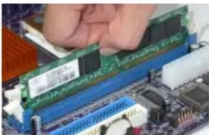
Table A: DDR (memory module) QVL (Qualified Vendor List)
The following DDR400 memory modules have been tested and qualified for use with this motherboard.
| Size | Vendor | Module Name |
| 128MB | Infineon | HYS64D16301GU-5-B |
| NANYA | NT128D64SH4B1G-5T | |
| 256MB | Infineon | HYS64D32300GU-5-B |
| Infincon | HYS64D32300HU-5-C | |
| Micron | MT16VDDT3264AG-403B2 | |
| Micron | MT8VDDT3264AG-40BC4 | |
| NANYA | NT256D64S88B1G-5T | |
| SAMSUNG | M368L3223DTM-CC4 | |
| 512MB | Infineon | HYS64D64320HU-5-C |
| Micron | MT16VDDT6464AG-40BC4 | |
| NANYA | NT512D64S8HB1G-5T | |
| SAMSUNG | M368L6423DTM-CC4 | |
| SAMSUNG | M368L6423ETM-CCC |
Installing a Hard Disk Drive/CD-ROM
This section describes how to install IDE devices such as a hard disk drive and a CD-ROM drive.
About IDE Devices
Your motherboard has a primary and secondary IDE channel interface (IDE1 and IDE2). An IDE ribbon cable supporting two IDE devices is bundled with the motherboard.

You must orient the cable connector so that the pin1 (color) edge of the cable corresponds to the pin 1 of the I/O port connector.
IDE1: Primary IDE Connector
The first hard drive should always be connected to IDE1.


IDE2: Secondary IDE Connector
The second drive on this controller must be set to slave mode. The configuration is the same as IDE1.
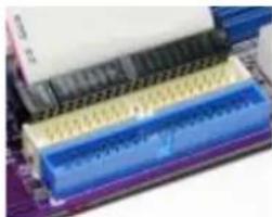
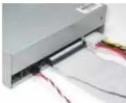
IDE devices enclose jumpers or switches used to set the IDE device as MASTER or SLAVE. Refer to the IDE device user's manual. Installing two IDE devices on one cable, ensure that one device is set to MASTER and the other device is set to SLAVE. The documentation of your IDE device explains how to do this.
About UltraDMA
This motherboard supports UltraDMA 100/66/33. UDMA is a technology that accelerates the performance of devices in the IDE channel. To maximize performance, install IDE devices that support UDMA and use 80-pin IDE cables that support UDMA 100/66.
About SATA Connectors
Your motherboard features two SATA connectors supporting a total of two drives. SATA, or Serial ATA (Advanced Technology Attachment) is the standard interface for the IDE hard drives which are currently used in most PCs. These connectors are well designed and will only fit in one orientation. Locate the SATA connectors on the motherboard and follow the illustration below to install the SATA hard drives.
Installing Serial ATA Hard Drives
To install the Serial ATA (SATA) hard drives, use the SATA cable that supports the Serial ATA protocol. This SATA cable comes with an SATA power cable. You can connect either end of the SATA cable to the SATA hard drive or the connector on the motherboard.

SATA cable (optional)

SATA power cable (optional)
Refer to the illustration below for proper installation:
1 Attach either cable end to the connector on the motherboard.
2 Attach the other cable end to the SATA hard drive.
3 Attach the SATA power cable to the SATA hard drive and connect the other end to the power supply.


This motherboard does not support the "Hot-Plug" function.
Installing a Floppy Diskette Drive
The motherboard has a floppy diskette drive (FDD) interface and ships with a diskette drive ribbon cable that supports one or two floppy diskette drives. You can install a 5.25-inch drive and a 3.5-inch drive with various capacities. The floppy diskette drive cable has one type of connector for a 5.25-inch drive and another type of connector for a 3.5-inch drive.

You must orient the cable connector so that the pin 1 (color) edge of the cable corresponds to the pin 1 of the I/O port connector.
FDD1: Floppy Disk Connector
This connector supports the provided floppy drive ribbon cable. After connecting the single end to the onboard floppy connector, connect the remaining plugs on the other end to the floppy drives correspondingly.

Installing Add-on Cards
The slots on this motherboard are designed to hold expansion cards and connect them to the system bus. Expansion slots are a means of adding or enhancing the motherboard's features and capabilities. With these efficient facilities, you can increase the motherboard's capabilities by adding hardware that performs tasks that are not part of the basic system.

AGP Express Slot
The AGP Express slot is used to install a graphics adapter that emulates the AGP function. In order to get better performance and compatibility on our special design AGP Express slot, we recommend users use one of the AGP graphics cards that have been tested by our company. Please refer to page 21 for the "supported list".
PCI Slot
This motherboard is equipped with three standard PCI slots. PCI stands for Peripheral Component Interconnect and is a bus standard for expansion cards, which for the most part, is a supplement of the older ISA bus standard. The PCI slots on this board are PCI v2.3 compliant.
CNR1 Slot (optional)
This slot is used to insert CNR cards with Modem and Audio functionality.

Before installing an add-on card, check the documentation for the card carefully. If the card is not Plug and Play, you may have to manually configure the card before installation.
[Unreadable]
Follow these instructions to install an add-on card:
1 Remove a blanking plate from the system case corresponding to the slot you are going to use.
2 Install the edge connector of the add-on card into the expansion slot. Ensure that the edge connector is correctly seated in the slot.
3 Secure the metal bracket of the card to the system case with a screw.


For some add-on cards, for example graphics adapters and network adapters, you have to install drivers and software before you can begin using the add-on card.
Table A: Supported List of AGP Express Slot
The following VGA chipsets have been tested and qualified for use with this motherboard.
| VGA Chip | Model name | AGP 4X/8X |
| NVIDIA | GAWWARD Geforce3 TI200 128MB | 4X |
| Leadtek A250TDT TI4400 128MB | ||
| Leadtek WinFast A250 LE TD GF4 TI4200 64MB | ||
| BiTC GeForce4 MX440 64MB | 8X | |
| Gigabyte GeForce FX5700U 128MB | ||
| Leadtek WinFast A350 GeForce FX5900-TDH 256MB | ||
| Leadtek WinFast A380 GeForce FX5950 Ultra TDM 256MB | ||
| Leadtek WinFast A280 LE TD GF4 TI4200 128MB | ||
| MSI GeForce FX5800-TD 128MB | ||
| Millennium Silver TI4600 128MB | ||
| Triplex GeForce FX5200 64MB | ||
| ATI | ATI R7000 64MB | 4X |
| ATI R7500 64MB | ||
| ATI R9000 128MB | ||
| ATI Radeon 9500 64MB | ||
| ATI Radcon 9700PRO 128MB | ||
| ECS R9200LE-64T |

For the latest supported AGP graphics list, please visit our website:
www.ecs.com.tw/ECSWeb/Support/agp.aspx
Once the AGP VGA card is properly installed under Windows 2000 or Windows XP, the below picture will be shown. And users will see the icon 🔍 if the driver is not well-installed in the system.
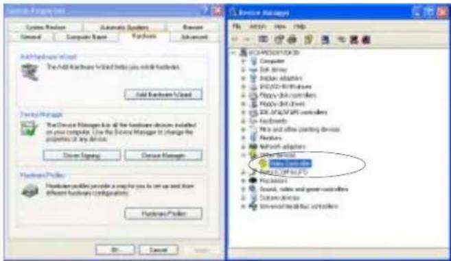

-
It is normal to see the icon as the onboard VGA card is "Disabled".
-
To install the system with an add-on AGP VGA card, users must make sure to install the driver of add-on AGP VGA card before you install the onboard VGA driver. If the onboard VGA driver has already been installed before you install the add-on AGP VGA card, the system will set the onboard VGA as the primary graphics adapter automatically. In this situation, if you want to install the add-on AGP VGA card, you need to remove the onboard VGA driver first, then install the add-on AGP VGA card and its driver, or it will "no display" when your monitor connects to AGP VGA card.
-
Please note that if both of the onboard VGA and the AGP Express Slot are connected to the monitors, the system will set the AGP Express slot as the primary graphics adapter automatically, and the onboard VGA will be functionless.
Dual Monitor
In order to enable “Dual Monitor” Function, users must have “Two Monitors”, “Two Graphics Devices” (one is for AGP VGA card; the other one is for onboard VGA) and Windows 2000 or Windows XP that supports the Dual Monitor Function. Users must follow the “Dual Monitor Installation” shown as below.
Dual Monitor Installation (For Windows XP)
If the onboard VGA is already installed, and you want to use the add-on AGP VGA card, you may follow the installation step 1-6 as the following.
However, users may go to Step 4 directly if the add-on AGP VGA card is already installed; then turned on the onboard VGA devies for “secondary display”.
Step 1: Remove the Onboard VGA Driver
Go to "Control Panel"
Choose "Add or Remove Programs"
Choose "Intel® Extreme Graphics Driver"
Click "Remove"
Shut down the computer
Step 2: Install the Add-on AGP VGA Card
Shut down the system
Install the add-on AGP VGA card in the AGP Express slot
Turn on the computer

When you turn on the system, windows might report Found New Hardware Wizard, "Video Controller (VGA Compatible)" or "Video Controller". When you see the Found New Hardware Wizard dialogue box, DO NOT insert any disk in your CD/DCD ROM before clicking on the "Next" button. The Windows Auto-search will not be finished till it can't search the related driver.
Step 3: Install the Add-on AGP VGA Card Driver
Install the add-on AGP VGA Card driver
Restart the computer
Step 4: Install the Onboard VGA Driver
Install the onboard VGA driver from our support CD to utilize Dual Monitor Function. Please refer to the follow path.
CD-ROM:\VGA\Intel845_865\Win2K&XP\Graphics\Setup.exe
Restart the computer.

If the add-on AGP VGA card driver and onboard VGA drivers are installed, the dual-monitor display will be enabled. As soon as it is enabled, follow the instructions to view the status of the dual-monitor display or adjust the parameters of the two monitors.
Step 5: Right click the desktop. Select "Properties" as shown in the below.

Step 6: Select "Display Properties". Click "Settings"
Then the parameters of the two minitors can be adjusted.
Dual Monitor Installation (For Windows 2000)
If the onboard VGA is already installed, and you want to use the add-on AGP VGA card, you may follow the installation step 1-6 as the following.
However, users may go to Step 4 directly if the add-on AGP VGA card is already installed; then turned on the onboard VGA devices for "secondary display".
Step 1: Install the Add-on AGP VGA Card
Shut down the system
Install your add-on AGP VGA card in the AGP Express slot
Turn on the computer
Step 2: Install the Add-on AGP VGA Card Driver
Install the add-on AGP VGA card driver
Restart the computer

Windows might report Found New Hardware Wizard once the system is turned on. When you see the Found New Hardware Wizard dialogue box, please click on "Cancel" and DO NOT install the onboard VGA driver.
Step 3: Remove the Onboard VGA Driver
Go to "Control Panel"
Choose "Add or Remove Programs"
Choose "Intel ⑧ Extreme Graphics Driver" Click (D++, R) and Print the
Click "Remove" and Restart the computer

When you turn on the system, windows might report Found New Hardware Wizard, "Video Controller (VGA Compatible)" or "Video Controller". When you see the Found New Hardware Wizard dialogue box, DO NOT insert any disk in your CD/DVD-ROM before clicking on the "Next" button. The Windows Auto-search will not be finished until it can't search the related driver.
Step 4: Install the Onboard VGA Driver
Install the Onboard VGA driver from our support CD to utilize Dual Monitor Function. Please refer to the below path.
CD-ROM:\VGA\Intel845_865\Win2K&XP\Graphics\Setup.exe
Restart the computer

If the add-on AGP VGA card driver and onboard VGA drivers are installed, the dual-monitor display will be enabled. As soon as it is enabled, follow the instructions to view the status of the dual-monitor display or adjust the parameters of the two monitors.
Step 5: Right clock the desktop. Select "Properties" as shown in the below.
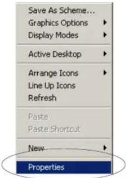
Step 6: Select "Display Properties", then click "Settings".
Then the parameters of the two monitors can be adjusted.
Connecting Optional Devices
Refer to the following for information on connecting the motherboard's optional devices:

SPDIFO1: SPDIF out header
This is an optional header that provides an S/PDIF (Sony/Philips Digital Interface) output to digital multimedia device through optical fiber or coaxial connector.
| Pin Signal Name Function | |
| 1 SPDIF SPDIF digital output | |
| 2 +5VA 5V analog Power | |
| 3 Key No pin | |
| 4 GND Ground | |
AUDIO1: Front Panel Audio header
This header allows the user to install auxiliary front-oriented microphone and line-out ports for easier access.
| Pin Signal Name Function | ||
| 1 AUD_MIC Front Panel | Microphone input signal | |
| 2 AUD_GND Ground used by Analog Audio Circuits | ||
| 3 AUD_MIC_BIAS Microphone Power | ||
| 4 AUD_VCC Filtered +5V used by Analog Audio Circuits | ||
| 5 AUD_F_R Right Channel audio signal to Front Panel | ||
| 6 | AUD_RET_R | Right Channel Audio signal to Return from Front Panel |
| 7 REVD Reserved | ||
| 8 Key No Pin | ||
| 9 | AUD_F_L | Left Channel Audio signal to Front Panel |
| 10 | AUD_RET_L | Left Channel Audio signal to Return from Front Panel |
USB3/4: Front Panel USB headers
The motherboard has four USB ports installed on the rear edge I/O port array. Additionally, some computer cases have USB ports at the front of the case. If you have this kind of case, use auxiliary USB connector to connect the front-mounted ports to the motherboard.
| Pin Signal Name Function | |
| 1 USBPWR Front Panel USB Power | |
| 2 USBPWR Front Panel USB Power | |
| 3 USB_FP_P0- USB Port 0 Negative Signal | |
| 4 USB_FP_P1- USB Port 1 Negative Signal | |
| 5 USB_FP_P0+ USB Port 0 Positive Signal | |
| 6 USB_FP_P1+ USB Port 1 Positive Signal | |
| 7 GND Ground | |
| 8 GND Ground | |
| 9 Key No pin | |
| 10 USB_FP_OC0 Overcurrent Signal | |

Please make sure that the USB cable has the same pin assignment as indicated above. A different pin assignment may cause damage or system hang-up.
SATA1/2: Serial ATA connectors
These connectors are use to support the new Serial ATA devices for the highest date transfer rates (150 MB/s), simpler disk drive cabling and easier PC assembly. It eliminates limitations of the current Parallel ATA interface. But maintains register compatibility and software compatibility with Parallel ATA.
| Pin Signal Name Pin Signal Name | ||
| Pin Signal Name Function | ||
| 1 Ground 2 TX+ | ||
| 3 TX-4 Ground | ||
| 5 RX-6 RX+ | ||
| 7 Ground - - | ||
COM2: Onboard serial port header
Connect a serial port extension bracket to this header to add a second serial port to your system.
| Pin Signal Name Function | |
| 1 NDCDB | Data carry detect |
| 2 NSINB | Serial Data In |
| 3 NSOUTB Serail Data Out | |
| 4 NDTRB | Data terminal ready |
| 5 GND Ground | |
| 6 NDSRB | Date set ready |
| 7 NRTSB | Request to send |
| 8 NCTSB | Clear to send |
| 9 NRIB Ring Indicator | |
| 10 KEY | Key |
IR1: Infrared header
The mainboard supports an Infrared (IR1) data port. Infrared ports allow the wireless exchange of information between your computer and similarly equipped devices such as printers, laptops, Personal Digital Assistants (PDAs), and other computers.
| Pin | Signal Name | Function |
| 1 | Not Assigned | Not assigned |
| 2 | Key No pin | |
| 3 | +5V IR Power | |
| 4 | GND Ground | |
| 5 | IRTX IrDA serial output | |
| 6 | IRTX IrDA serial input |
CD_IN: Analog Audio Input header
| Pin Signal Name Function | |
| 1 CD in_L CD In left channel | |
| 2 GND Ground | |
| 3 GND Ground | |
| 4 CD in_R CD In right channel | |
1394A2: Onboard IEEE 1394a header (optional)
Connect this header to any device with IEEE 1394a interface.
| Pin Signal Name Pin Signal Name | |||
| 1 TPA+ 2 TPA- | |||
| 3 GND 4 GND | |||
| 5 TPB+ 6 TPB- | |||
| 7 Cable-Power 8 Cable-Power | |||
| 9 | Key Pin | 10 | GND |
Connecting I/O Devices
The backplane of the motherboard has the following I/O ports:
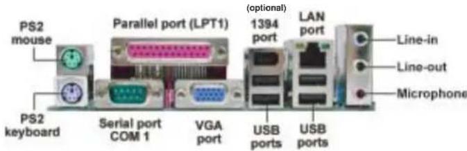
PS2 Mouse Use the upper PS/2 port to connect a PS/2 pointing device.
PS2 Keyboard Use the lower PS/2 port to connect a PS/2 keyboard.
Parallel Port (LPT1) Use LPT1 to connect printers or other parallel communications devices.
Serial Port (COM1) Use the COM port to connect serial devices such as mice or fax/modems. COM1 is identified by the system as COM1/3.
VGA Port Connect your monitor to the VGA port.
LAN Port (optional) Connect an RJ-45 jack to the LAN port to connect your computer to the Network.
USB Ports Use the USB ports to connect USB devices.
1394 Port (optional) Connect your 1394a device to any device with Firewire interface.
Audio Ports Use the three audio ports to connect audio devices. The first jack is for stereo line-in signal. The second jack is for stereo line-out signal. The third jack is for microphone.
This concludes Chapter 2. The next chapter covers the BIOS.
√
★★○□
About the Setup Utility
The computer uses the latest Award BIOS with support for Windows Plug and Play. The CMOS chip on the motherboard contains the ROM setup instructions for configuring the motherboard BIOS.
The BIOS (Basic Input and Output System) Setup Utility displays the system's configuration status and provides you with options to set system parameters. The parameters are stored in battery-backed-up CMOS RAM that saves this information when the power is turned off. When the system is turned back on, the system is configured with the values you stored in CMOS.
The BIOS Setup Utility enables you to configure:
- Hard drives, diskette drives and peripherals
• Video display type and display options - Password protection from unauthorized use
• Power Management features
The settings made in the Setup Utility affect how the computer performs. Before using the Setup Utility, ensure that you understand the Setup Utility options.
This chapter provides explanations for Setup Utility options.
The Standard Configuration
A standard configuration has already been set in the Setup Utility. However, we recommend that you read this chapter in case you need to make any changes in the future.
This Setup Utility should be used:
- when changing the system configuration
- when a configuration error is detected and you are prompted to make changes to the Setup Utility
- when trying to resolve IRQ conflicts
- when making changes to the Power Management configuration
- when changing the password or making other changes to the Security Setup
Entering the Setup Utility
When you power on the system, BIOS enters the Power-On Self Test (POST) routines. POST is a series of built-in diagnostics performed by the BIOS. After the POST routines are completed, the following message appears:
Press DEL to enter SETUP
Pressing the delete key accesses the BIOS Setup Utility:
Phoenix-AwardBIOS CMOS Setup Utility:
| ►Standard CMOS Features | ►Frequency Control |
| ►Advanced BIOS Features Load Fail Safe Defaults | |
| ►Advanced Chipset Features Load Optimized Defaults | |
| ►Integrated Peripherals Set Supervisor Password | |
| ►Power Management Setup Set User Password | |
| ►PnP/PCI Configurations Save & Exit Setup | |
| ►PC Health Status Exit Without Saving | |
| Esc: Quit ↑↓→← : Select ItemF10: Save & Exit Setup | |
| Time, Date, Hard Disk Type... | |
BIOS Navigation Keys
The BIOS navigation keys are listed below:
| KEY FUNCTION |
| ESC Exits the current menu |
| ←↑↓→←↑c=ells through the items on a menu |
| +/-/PU/PD Modifies the selected field's values |
| F10 Saves the current configuration and exits setup |
| F1 Displays a screen that describes all key functions |
| F5 Loads previously saved values to CMOS |
| F6 Loads a minimum configuration for troubleshooting |
| F7 Loads an optimum set of values for peak performance |
Updating the BIOS
You can download and install updated BIOS for this motherboard from the manufacturer's Web site. New BIOS provides support for new peripherals, improvements in performance, or fixes for known bugs. Install new BIOS as follows:
1 If your motherboard has a BIOS protection jumper, change the setting to allow BIOS flashing.
2 If your motherboard has an item called Firmware Write Protect in Advanced BIOS features, disable it. (Firmware Write Protect prevents BIOS from being overwritten.
3 Create a bootable system disk. (Refer to Windows online help for information on creating a bootable system disk.)
4 Download the Flash Utility and new BIOS file from the manufacturer's Web site. Copy these files to the system diskette you created in Step 3.
5 Turn off your computer and insert the system diskette in your computer's diskette drive. (You might need to run the Setup Utility and change the boot priority items on the Advanced BIOS Features Setup page, to force your computer to boot from the floppy diskette drive first.)
6 At the A:\ prompt, type the Flash Utility program name and press
7 Type the filename of the new BIOS in the "File Name to Program" text box. Follow the onscreen directions to update the motherboard BIOS.
8 When the installation is complete, remove the floppy diskette from the diskette drive and restart your computer. If your motherboard has a Flash BIOS jumper, reset the jumper to protect the newly installed BIOS from being overwritten.
Using BIOS
When you start the Setup Utility, the main menu appears. The main menu of the Setup Utility displays a list of the options that are available. A highlight indicates which option is currently selected. Use the cursor arrow keys to move the highlight to other options. When an option is highlighted, execute the option by pressing
Some options lead to pop-up dialog boxes that prompt you to verify that you wish to execute that option. Other options lead to dialog boxes that prompt you for information.
Some options (marked with a triangle ▶) lead to submenus that enable you to change the values for the option. Use the cursor arrow keys to scroll through the items in the submenu.
In this manual, default values are enclosed in parenthesis. Submenu items are denoted by a triangle ▶.
Standard CMOS Features
This option displays basic information about your system.
Phoenix-AwardBIOS CMOS Setup Utility Standard CMOS Features
| Date (mm:dd:yy) Mon, Sep 17 2004Time (hh:mm:ss) 13 : 4 : 54IDE Channel 0 MasterIDE Channel 0 SlaveIDE Channel 1 MasterIDE Channel 1 SlaveDrive A [1.44M, 3.5 in.]Floppy 3 Mode Support [Disabled]Video [EGA\VGA]Halt On [All Errors]Base Memory 640KExtended Memory 65535KTotal Memory 1024K | Item Help |
| Menu Level ▶Change the day, month, year and century. |
| ↑↓→←:Move Enter: Select +/-/PU/PD:Value F10:Save ESC:Exit F1:General HelpF5:Previous Values F6:Fail-Safe Defaults F7:Optimized Defaults |
Date and Time
The Date and Time items show the current date and time on the computer. If you are running a Windows OS, these items are automatically updated whenever you make changes to the Windows Date and Time Properties utility.
▶IDE Devices (None)
Your computer has two IDE channels (Primary and Secondary) and each channel can be installed with one or two devices (Master and Slave). In addition, this motherboard supports two SATA channels (Primary and Secondary) and each channel allows one SATA device to be installed. Use these items to configure each device on the IDE channel.
Press
Phoenix-AwardBIOS CMOS Setup Utility IDE Primary Master
| IDE HDD Auto-Detection [Press Enter]IDE Channel 0 Master [Auto]Access Mode [Auto]Capacity 0 MBCylinder 0Head 0Precomp 0Landing Zone 0Sector 0 | Item Help |
| Menu Level ▶▶To auto-detect the HDD's size, head...on this channel |
| ↑↓→←:Move Enter: Select +/-/PU/PD:Value F10:Save ESC:Exit F1:General HelpF5:Previous Values F6:Fall-Safe Defaults F7:Optimized Defaults |
IDE HDD Auto-Detection
Press

If you are setting up a new hard disk drive that supports LBA mode, more than one line will appear in the parameter box. Choose the line that lists LBA for an LBA drive.

IDE Channel 0/1 Master/Slave (Auto)
Leave this item at Auto to enable the system to automatically detect and configure IDE devices on the channel. If it fails to find a device, change the value to Manual and then manually configure the drive by entering the characteristics of the drive in the items described below.
Refer to your drive's documentation or look on the drive casing if you need to obtain this information. If no device is installed, change the value to None.

Before attempting to configure a hard disk drive, ensure that you have the configuration information supplied by the manufacturer of your hard drive. Incorrect settings can result in your system not recognizing the installed hard disk.
Access Mode (Auto)
This item defines ways that can be used to access IDE hard disks such as LBA (Large Block Addressing). Leave this value at Auto and the system will automatically decide the fastest way to access the hard disk drive.
Press
Drive A (1.44M, 3.5 in./None)
These items define the characteristics of any diskette drive attached to the system. You can connect one or two diskette drives.
Floppy 3 Mode Support (Disabled)
Floppy 3 mode refers to a 3.5-inch diskette with a capacity of 1.2 MB. Floppy 3 mode is sometimes used in Japan.
Video (EGA/VGA)
This item defines the video mode of the system. This motherboard has a built-in VGA graphics system; you must leave this item at the default value.
Halt On (All Errors)
This item defines the operation of the system POST (Power On Self Test) routine. You can use this item to select which types of errors in the POST are sufficient to halt the system.
Base Memory, Extended Memory, and Total Memory
These items are automatically detected by the system at start up time. These are display-only fields. You cannot make changes to these fields.
Advanced BIOS Features
This option defines advanced information about your system.
Phoenix-AwardBIOS CMOS Setup Utility Advanced BIOS Features
![CPU Feature [Press Enter] Hard Disk Boot Priority [Press Enter] CPU L3 Cache [Enabled] Hyper-Threading Technology [Enabled] Quick Power On Self Test [Enabled] First Boot Device [Floppy] Second Boot Device [Hard Disk] Third Boot Device [CDROM] Boot Other Device [Enabled] Boot Up Floppy Seek [Disabled…](/content/2026/05/859275/images/12da78e7a38e9dd7856daf9e22036ec81d04a4feb483d8729b27d284b21e2399.jpg)
↑↓→← : Move Enter: Select +/-/PU/PD:Value F10:Save ESC:Exit F1:General Help F5:Previous Values F6:Fail-Safe Defaults F7:Optimized Defaults
CPU Feature (Press Enter)
Users please note that this function is only available for Prescott CPUs. Scroll to this item and press
Phoenix-AwardBIOS CMOS Setup Utility CPU Feature
| Delay Prior to thermal Thermal Management TM2 Bus Ratio [0 X] TM2 Bus VID Limit CPUID MaxVal [Disabled] NX BIOS Control [Disabled] | [16 Min] [Thermal Monitor 1] [0.8375V] | Item Help |
| Menu Level ▶▶Thermal Monitor 1 (On die throttling)Thermal Monitor 2 Ratio & VID transition |
↑↓→←: Move Enter: Select +/-/PU/PD:Value F10:Save ESC:Exit F1:General Help F5:Previous Values F6"Fail-Safe Defaults F7:Optimized
Delay Prior to Thermal (Thermal Monitor 1)
This item enables you to set the delay time before the CPU enters auto thermal mode.
Thermal Management (Thermal Monitor 1)
This item displays CPU's temperature and enables you to set a safe temperature to Prescott CPU.
TM2 Bus Ratio (0X)
This item helps you to set the frequency (bus ratio) of the throttled performance that will be initiated when the on-die sensor goes from not hot to hot. You may set the bus ratio number from 0-255. This feature is available when CPU supports Thermal Monitor 2.
TM2 Bus VID (0.8375V)
This item helps you to set the voltage of the throttled performance that will be initiated when the on-die sensor goes from not hot to hot. This feature is available when CPU supports Thermal Monitor 2.
This item can support Prescott CPUs for old OS. Users please note that under NT 4.0, it must be set "Enabled", while under WinXP, it must be set "Disabled".
NX BIOS Control (Disabled)
Users please leave this item in its default setting under Windows XP OS. Change the value to "Disabled" if users are to install Linux OS.
Press
▶ Hard Disk Boot Priority (Press Enter)
Scroll to this item and press
Phoenix-AwardBIOS CMOS Setup Utility Hard Disk Boot Priority
| 1. Pri. Master:2. Pri. Slave:3. Sec. Master:4. Sec. Slave:5. USBHDD0:6. USBHDD1:7. USBHDD2:8. Bootable Add-in Cards | Item Help |
| Menu Level ▶▶Use < ↑ >or < ↓>to select a device, then press <--> to move it up, or <-> to move it down the list. Pressto exit this menu. |
CPU L3 Cache (Enabled)
All Prescott processors that can be installed in this mainboard use Level 3 (L3) cache memory to improve performance. Leave this item at the default value for better performance. This item is only available when you use L3 cache supported CPU.
Hyper-Threading Technology (Enabled)
This item is only available when the chipset supports Hyper-Threading and you are using a Hyper-Threading CPU.
Quick Power On Self Test (Enabled)
Enable this item to shorten the power on testing (POST) and have your system start up faster. You might like to enable this item after you are confident that your system hardware is operating smoothly.
First/Second/Third Boot Device (Floppy/Hard Disk/CDROM)
Use these three items to select the priority and order of the devices that your system searches for an operating system at start-up time.
Boot Other Device (Enabled)
When enabled, the system searches all other possible locations for an operating system if it fails to find one in the devices specified under the First, Second, and Third boot devices.
Boot Up Floppy Seek (Disabled)
If this item is enabled, it checks the size of the floppy disk drives at start-up time. You don't need to enable this item unless you have a legacy diskette drive with 360K capacity.
Boot Up NumLock Status (On)
This item defines if the keyboard Num Lock key is active when your system is started.
Gate A20 Option (Fast)
This item defines how the system handles legacy software that was written for an earlier generation of processors. Leave this item at the default value.
Typematic Rate Setting (Disabled)
If this item is enabled, you can use the following two items to set the typematic rate and the typematic delay settings for your keyboard.
- Typematic Rate (Chars/Sec): Use this item to define how many characters per second are generated by a held-down key.
- Typematic Delay (Msec): Use this item to define how many milliseconds must elapse before a held-down key begins generating repeat characters.
Security Option (Setup)
If you have installed password protection, this item defines if the password is required at system start up, or if it is only required when a user tries to enter the Setup Utility.
APIC Mode (Enabled)
This item allows you to enable or disable the APIC (Advanced Programmable Interrupt Controller) mode. APIC provides symmetric multi-processing (SMP) for systems, allowing support for up to 60 processors.
OS Select For DRAM > 64 MB (Non-OS2)
This item is only required if you have installed more than 64 MB of memory and you are running the OS/2 operating system. Otherwise, leave this item at the default.
HDD S.M.A.R.T Capability (Disabled)
The S.M.A.R.T. (Self-Monitoring, Analysis, and Reporting Technology) system is a diagnostics technology that monitors and predicts device performance. S.M.A.R.T. software resides on both the disk drive and the host computer.
Report No FDD For WIN 95 (Yes)
This item determines whether the BIOS will report no FDD for Windows 95 OS.
Delay for HDD (Secs) (0)
Users may set a delay from 1 to 15 seconds in the cold boot process. Some hard disk drives need extra time to spin up in order to identify correctly. If the system does not start after the memory test, try to add tomes in this field.
Small Logo (EPA) Show (Disabled)
Enables or disables the display of the EPA logo during boot.
Advanced Chipset Features
These items define critical timing parameters of the motherboard. You should leave the items on this page at their default values unless you are very familiar with the technical specifications of your system hardware. If you change the values incorrectly, you may introduce fatal errors or recurring instability into your system.
Phoenix-AwardBIOS CMOS Setup Utility Advanced Chipset Features
![DRAM Timing Selectable [By SPD] CAS Latency Time [2] Active to Precharge Delay [8] DRAM RAS# to CAS# Delay [4] DRAM RAS# Precharge [4] Memory Frequency For [Auto] System BIOS Cacheable [Disabled] Video BIOS Cacheable [Disabled] AGP Aperature Size (MB) [128] Init Display First [PCI Slot] ** Photon Ac…](/content/2026/05/859275/images/0e6a0111501bc55b5f1d8ef314ee6775faee27bff19a46c3bc49b9c4eb4e2a37.jpg)
↑↓→←:Move Enter: Select +/-/PU/PD:Value F10:Save ESC:Exit F1:General Help F5:Previous Values F6:Fail-Safe Defaults F7:Optimized Defaults
DRAM Timing Selectable (By SPD)
Enables you to select the CAS latency time in HCLKs of 2, 2.5, or 3. The value is set at the factory depending on the DRAM installed. Do not change the values in this field unless you change specifications of the installed DRAM or the installed CPU.
CAS Latency Time (2)
This item controls the timing delay (in clock cycles) before the DRAM starts a read command after receiving it.
Active to Precharge Delay (8)
This precharge time is the number of cycles it takes for DRAM to accumulate its charge before refresh.
DRAM RAS# to CAS# Delay (4)
This field lets you insert a timing delay between the CAS and RAS strobe signals, used when DRAM is written to, read from, or refreshed. Disabled gives faster performance; and Enabled gives more stable performance.
DRAM RAS# Precharge (4)
Select the number of CPU clocks allocated for the Row Address Strobe (RAS#) signal to accumulate its charge before the DRAM is refreshed. If insufficient time is allowed, refresh may be incomplete and data lost.
Memory Frequency For (Auto)
This item sets the main memory frequency. When you used an external graphics card, you can adjust this to enable the best performance for your system.
System BIOS Cacheable (Disabled)
When this item is enabled, the System BIOS will be cached for faster execution.
Video BIOS Cacheable (Disabled)
When this is enabled, the Video RAM will be cached resulting to better performance. However, if any program was written to this memory area, this may result in system error.
AGP Aperture Size (MB) (128)
This item defines the size of the aperture if you use an AGP graphics adapter. The AGP aperture refers to a section of the PCI memory address range used for graphics memory. We recommend that you leave this item at the default value.
Init Display First (PCI Slot)
This item allows you to choose the primary display card.
Fast Chip Select (Auto)
This item allows you to read the Data transfer from CPU to GMCH.
CPC Addr/Control (Auto)
This item allows you to increase the performance when DDR400 DIMM is installed and set this item to "Enabled". However, this might cause the system to become UNSTEADY.
Turbo Mode (Auto)
This item allows you to increase the performance of CPU L2 cache timing at high speed.
On-Chip VGA (Enabled)
This item allows you to enable or disable the onboard VGA function.
On-Chip Frame Buffer Size (8MB)
This item allows you to set the onboard frame buffer size, ranging from 1MB, 8MB, to 16MB.
Boot Display (Auto)
This item allows you to set the boot display function to be "Auto", "CRT", "EFP", "TV", "CRT+EFP", or "CRT+TV".
Integrated Peripherals
These options display items that define the operation of peripheral components on the system's input/output ports.
Phoenix-AwardBIOS CMOS Setup Utility Integrated Peripherals
| ► OnChip IDE Device [Press Enter] ► Onboard Device [Press Enter] ► SuperIO Device [Press Enter] | Item Help |
| Menu Level ► |
↑↓→←:Move Enter: Select +/-/PU/PD:Value F10:Save ESC:Exit F1:General Help F5:Previous Values F6:Fail-Safe Defaults F7:Optimized Defaults
▶ OnChip IDE Device
Scroll to this item and press
Phoenix-AwardBIOS CMOS Setup Utility OnChip IDE Device
| IDE HDD Block Mode [Enabled] On-chip Primary PCI IDE [Enabled] IDE Primary Master PIO [Auto] IDE Primary Slave PIO [Auto] IDE Primary Master UDMA [Auto] IDE Primary Slave UDMA [Auto] On-chip Secondary PCI IDE [Enabled] IDE Secondary Master PIO [Auto] IDE Secondary Slave PIO [Auto] IDE Secondary Master UDMA [Auto] IDE Secondary Slave UDMA [Auto] ATA 66/100 Cable Msg [Enabled] *** On-Chip Serial ATA Setting*** SATA Mode [IDE] On-chip Serial ATA [Disabled] Serial ATA Port0 Mode [Primary Master] Serial ATA Port1 Mode Primary Master | Item Help |
| Menu Level ▶▶ |
↑↓→← : Move Enter: Select +/-/PU/PD:Value F10:Save ESC:Exit F1:General Help F5:Previous Values F6:Fail-Safe Defaults F7:Optimized Defaults
IDE HDD Block Mode (Enabled)
Block mode is also called block transfer, multiple commands, or multiple sector read/write. If your IDE hard drive supports block mode (most new drives do), select Enabled for automatic detection of the optimal number of block read/write per sector the drive can support.
On-Chip Primary/Secondary PCI IDE (Enabled)
This integrated peripheral controller contains an IDE interface with support for two IDE channels. Select Enabled to activate each channel separately.
IDE Primary/Secondary Master/Slave PIO (Auto)
Each IDE channel supports a master device and a slave device. These four items let you assign the kind of PIO (Programmed Input/Output) was used by the IDE devices. Choose Auto to let the system auto detect which PIO mode is best, or select a PIO mode from 0-4.
IDE Primary/Secondary Master/Slave UDMA (Auto)
Each IDE channel supports a master device and a slave device. This mainboard supports UltraDMA technology, which provides faster access to IDE devices. If you install a device that supports UltraDMA, change the appropriate item on this list to Auto. You may have to install the UltraDMA driver supplied with this mainboard in order to use an UltraDMA device.
ATA 66/100 Cable Msg (Enabled)
This item enables or disabled the display of the ATA 66/100 Cable Msg. If you install a device that supports UDMA, change the appropriate item on this list to Auto. You may have to install the UDMA driver supplied with this motherboard in order to use an UDMA device.
SATA Mode (IDE)
Use this item to select the mode of the Serial ATA.
Enables or disables the built-in on-chip Serial ATA.
Serial ATA Port0/Port1 Mode (Primary Master)
Use this item to select the SATA0 master or SATA1 master.
Press
▶ Onboard Device
Scroll to this item and press
Phoenix-AwardBIOS CMOS Setup Utility Onboard Device
![USB Controller [Enabled] USB 2.0 Controller [Enabled] USB Keyboard Support [Enabled] USB Mouse Support [Enabled] AC97 AUDIO [Auto] Onboard LAN Device [Enabled] Onboard LAN Boot ROM [Disabled] Onboard 1394 Device [Enabled] Item Help Menu Level ▶▶](/content/2026/05/859275/images/f7e6d0e9790aceb26fa1b611f1d0296cedc6613141428fa05daae1cbda1ad47c.jpg)
↑↓→←:Move Enter: Select +/-/PU/PD:Value F10:Save ESC:Exit F1:General Help F5:Previous Values F6:Fail-Safe Defaults F7:Optimized Defaults
USB Controller (Enabled)
This item enables the USB controller. Leave this at the default "Enabled" if you want to connect USB devices to your computer.
USB 2.0 Controller (Enabled)
Enable this item if want to use the USB 2.0.
USB Keyboard Support (Enabled)
This item allows the BIOS to interact with a USB keyboard or mouse to work with MS-DOS based utilities and non-Windows modes.
USB Mouse Support (Enabled)
Enable this item if you plan to use a mouse connected through the USB port in a legacy operating system (such as DOS) that does not support Plug and Play.
AC97 AUDIO (Enabled)
This option allows you to control the onboard AC97 audio. Disable this item if you are going to install a PCI audio add-on card.
Onboard LAN Device (Enabled)
This option allows you to enable or disable the onboard LAN function.
Onboard LAN Boot ROM (Disabled)
Use this item to enable and disable the booting from the onboard LAN or a network add-in card with a remote boot ROM installed.
Onboard 1394 Device (Enabled)
This option allows you to enable or disable the onboard 1394 function.
Press
▶SuperIO Device
Scroll to this item and press
Phoenix-AwardBIOS CMOS Setup Utility
SuperIO Device
![POWER ON Function [Hot Key] KB Power ON Password [Enter] Hot key Power ON [Ctrl-F12] Onboard FDC Controller [Enabled] Onboard Serial Port1 [3F8/IRQ4] UART 2 Mode Control [Disabled] UART Mode Select [Normal] RxD, TxD Active [Hi, Lo] IR Transmission Delay [Enabled] UR2 Duplex Mode [Half] Use IR Pins […](/content/2026/05/859275/images/a6794ecb4fcfd1f90f36df4db75e5c76ab9201d63b96d78a7c4d92582fc47f76.jpg)
↑↓→←:Move Enter:Select +/-/PU/PD:Value F10:Save ESC:Exit F1:General Help F5:Previous Values F6:Fail-Safe Defaults F7:Optimized Defaults
POWER ON Function (Hot Key)
This feature allows you to set the method by which your system can be turned on.
KB Power ON Password (Enter)
When the POWER ON Function is set to Password, use this item to set the password.
Hot Key Power On (Ctrl-F12)
When the POWER ON Function is set to Hot Key, use this item to set the hot key combination that turns on the system.
Onboard FDC Controller (Enabled)
Select Enabled if your system has a floppy disk controller (FDC) installed on the system board and you wish to use it. If you install an add-in FDC or the system has no floppy drive, select Disabled in this field.
Onboard Serial Port1 (3F8/IRQ4)
This option is used to assign the I/O address and interrupt request (IRQ) for onboard serial port1 (COM1).
UART 2 Mode Control (Disabled)
This item allows users to enable or disable the onboard UART2 mode control.
UART Mode Select (2F8/IRQ3)
This field is available if the “Onboard Serial Port 2” is set to any option but Disabled. UART Mode Select enables you to select the infrared communication protocol-Normal (default), IrDA, or ASKIR. IrDA is an infrared communication protocol with a maximum baud rate up to 115.2K bps. ASKIR is Sharp’s infrared communication protocol with a maximum baud rate up to 57.6K bps.
RxD, TxD Active (Hi, Lo)
This feature enables you to set the IR reception/transmission polarity as High or Low
IR Transmission Delay (Enabled)
This field enables you to set the whether the IR transmission rate will be delayed while converting to receiving mode.
UR2 Duplex Mode (Half)
This field is available when UART 2 Mode is set to either ASKIR or IrDA. This item enables you to determine the infrared function of the onboard infrared chip. The options are Full and Half (default). Full-duplex means you can transmit and receive data simultaneously. Half-duplex is the transmission of data in either transmitting or receiving, only one direction at a time.
Use IR Pins (IR-Rx2Tx2)
Please consult your IR peripheral documentation to select the correct setting of the TxD and RxD signals.
Onboard Parallel Port (378/IRQ7)
This option is used to assign the I/O address and interrupt request (IRQ) for the onboard parallel port.
Parallel Port Mode (ECP)
Enables you to set the data transfer protocol for your parallel port. There are four options: SPP (Standard Parallel Port), EPP (Enhanced Parallel Port), ECP (Extended Capabilities Port), and ECP+EPP.
SPP allows data output only. Extended Capabilities Port (ECP) and Enhanced Parallel Port (EPP) are bi-directional modes, allowing both data input and output. ECP and EPP modes are only supported with EPP- and ECP-aware peripherals.
ECP Mode Use DMA (3)
When the onboard parallel port is set tp ECP mode, the parallel port can use DMA3 or DMA1.
Power On After Power Fail (Off)
This item enables your computer to automatically restart or return to its last operating status after power returns from a power failure.
Press
Power Management Setup
This option lets you control system power management. The system has various power-saving modes including powering down the hard disk, turning off the video, suspending to RAM, and software power down that allows the system to be automatically resumed by certain events.
The power-saving modes can be controlled by timeouts. If the system is inactive for a time, the timeouts begin counting. If the inactivity continues so that the timeout period elapses, the system enters a power-saving mode. If any item in the list of Reload Global Timer Events is Enabled, then any activity on that item will reset the timeout counters to zero.
If the system is suspended or has been powered down by software, it can be resumed by a wake up call that is generated by incoming traffic to a modem, a LAN card, a PCI card, or a fixed alarm on the system realtime clock
Phoenix-AwardBIOS CMOS Setup Utility
Power Management Setup
![ACPI Suspend Type [S3 (STR)] Run VGABIOS If S3 Resume [Auto] Video Off Method [DPMS] Video Off In Suspend [Yes] Suspend Type [Stop Grant] Modern Use IRQ [3] Suspend Mode [Disabled] HDD Power Down [Disabled] Soft-Off by PWR-BTTN [Instant-Off] Resume by PCI PME [Enabled] Resume by Ring [Disabled] Resu…](/content/2026/05/859275/images/920e5124a642b4d934900903f4febef9c1c67381b14b76fac982ea41e588e85d.jpg)
↑↓→← :Move Enter: Select +/-/PU/PD:Value F10:Save ESC:Exit F1:General Help F5:Previous Values F6:Fail-Safe Defaults F7:Optimized Defaults
ACPI Suspend Type (S3(STR))
Use this item to define how your system suspends. In the default, S1 (POS), the suspend mode is equivalent to a software power down. If you select S3 (STR), the suspend mode is suspend to RAM, i.e., the system shuts down with the exception of a refresh current to the system memory.
Run VGABIOS if S3 Resume (Auto)
Use this item to initialize the VGA BIOS from S3 (Suspend to RAM) sleep state.
Video Off Method (DPMS)
This item defines how the video is powered down to save power. This item is set to DPMS (Display Power Management Software) by default.
Video Off In Suspend (Yes)
This option defines if the video is powered down when the system is put into suspend mode.
Suspend Type (Stop Grant)
If this item is set to the default Stop Grant, the CPU will go into Idle Mode during power saving mode.
MODEM Use IRQ (3)
If you want an incoming call on a modem to automatically resume the system from a power-saving mode, use this item to specify the interrupt request line (IRQ) that is used by the modem. You might have to connect the fax/modem to the motherboard Wake On Modem connector for this feature to work.
Suspend Mode (Disabled)
The CPU clock will be stopped and the video signal will be suspended if no Power Management events occur for a specified length of time. Full power function will return when a Power Management event is detected. Options are from 1 Min to 1 Hour and Disabled.
HDD Power Down (Disabled)
The IDE hard drive will spin down if it is not accessed within a specified length of time. Options are from 1 Min to 15 Min and Disable.
Soft-Off by PWR-BTTN (Instant-Off)
Under ACPI (Advanced Configuration and Power management Interface) you can create a software power down. In a software power down, the system can be resumed by Wake Up Alarms. This item lets you install a software power down that is controlled by the power button on your system. If the item is set to Instant-Off, then the power button causes a software power down. If the item is set to Delay 4 Sec. then you have to hold the power button down for four seconds to cause a software power down.
Resume by PCI PME (Enabled)
This item specifies whether the system will be awakened from power saving modes when activity or input signal of the specified hardware peripheral or component is detected.
Resume by Ring (Disabled)
An input signal on the serial Ring indicator (RI) line (in other words, and incoming call on the modem) awakens the system from a soft off state.
Resume by USB (S3) (Disabled)
This option allows the activity of the USB devices (keyboard and mouse) to wake-up the system from S3 sleep state.
Resume by Alarm (Disabled)
When set to Enabled, additional fields become available and you can set the date (day of the month), hour, minute and second to turn on your system. When set to 0 (zero) for the day of the month, the alarm will power on your system every day at the specified time.
** Reload Global Timer Events **
This field indicates which events waken the system from power saving mode.
Primary/Secondary IDE 0/1 (Disabled)
When this item is enabled, the system power will resume the system from a power saving mode if there is any activity on primary or secondary IDE channel 0 or 1.
When this item is enabled, the system power will resume the system from a power saving mode if there is any activity on FDD, COM, or LPT port.
PCI PIRQ [A-D] # (Disabled)
When this item is enabled, the system power will resume the system from a power saving mode if there is any activity on PCI or PIRQ devices.
PNP/PCI Configurations
This section describes configuring the PCI bus system. PCI (Peripheral Component Interconnect) is a system, which allows I/O devices to operate at speeds nearing CPU's when they communicate with own special components. All the options describes in this section are important and technical and it is strongly recommended that only experienced users should make any changes to the default settings.
Phoenix-AwardBIOS CMOS Setup Utility PnP/PCI Configurations
| Reset Configuration Data [Disabled] Resources Controlled By [Auto(ESCD)] x IRQ Resources Press Enter PCI/VGA Palette Snoop [Disabled] Assign IRQ For USB [Enabled] INT Pin 1 Assignment [Auto] INT Pin 2 Assignment [Auto] INT Pin 3 Assignment [Auto] INT Pin 4 Assignment [Auto] INT Pin 5 Assignment [Auto] INT Pin 6 Assignment [Auto] INT Pin 7 Assignment [Auto] INT Pin 8 Assignment [Auto] | Item Help |
| Menu Level ▶▶ Default is Disabled. Select Enabled to reset Extended System Configuration Data (ESCD) when you exit Setup If you have installed a new add-on and the system reconfiguration has caused such a serious conflict that the OS cannot boot |
↑↓→←:Move Enter: Select +/-/PU/PD:Value F10:Save ESC:Exit F1:General Help F5:Previous Values F6:Fail-Safe Defaults F7:Optimized Defaults
Reset Configuration Data (Disabled)
When you enable this item and restart the system, any Plug and Play configuration data stored in the BIOS Setup is cleared from memory.
Resources Controlled By (Auto(ECSD))
You should leave this item at the default Auto(ESCD). Under this setting, the system dynamically allocates resources to Plug and Play devices as they are required. If you cannot get a legacy ISA (Industry Standard Architecture) expansion card to work properly, you might be able to solve the problem by changing this item to Manual, and then opening up the IRQ Resources submenu.
- In the IRQ Resources submenu, if you assign an IRQ to Legacy ISA, then that Interrupt Request Line is reserved for a legacy ISA expansion card. Press
PCI/VGA Palette Snoop (Disabled)
This item is designed to overcome problems that can be caused by some non-standard VGA cards. This board includes a built-in VGA system that does not require palette snooping so you must leave this item disabled.
Assign IRQ For USB (Enabled)
“Enable” or “Disable” this item when users are to assign IRQ for the USB interface onboard.
INT Pin1\~8 Assignment (Auto)
Identifies the interrupt request (IRQ) line assigned to a device connected to the PCI interface of your system.
PC Health Status
On motherboards that support hardware monitoring, this item lets you monitor the parameters for critical voltages, critical temperatures, and fan speeds.
Phoenix-AwardBIOS CMOS Setup Utility PC Health Status
| Target Temperature [Disabled]Shutdown Temperature [Disabled]Vcore (V)3.30 V5.00 V12.00 V1.50 V5VSB (V)VBT (V)Current System TemperatureCurrent CPU TemperatureCurrent System FAN SpeedCurrent CPU FAN SpeedCurrent Power FAN Speed | Item Help |
| Menu Level ▶ |
↑↓→←:Move Enter: Select +/-/PU/PD:Value F10:Save ESC:Exit F1:General Help F5:Previous Values F6:Fail-Safe Defaults F7:Optimized Defaults
Target Temperature (Disabled)
This item enables throttling when CPU targets the temperature.
Shutdown Temperature (Disabled)
Enables you to set the maximum temperature the system can reach before powering down.
System Component Characteristics
These items allow end users and technicians to monitor data provided by the BIOS on this motherboard. You cannot make changes to these fields.
- Current CPU/System Temperature
- CPU Fan Speed
- CPU Core Voltage
- Battery Voltage
Frequency Control
This item enables you to set the clock speed and system bus for your system. The clock speed and system bus are determined by the kind of processor you have installed in your system.
Phoenix-AwardBIOS CMOS Setup Utility
Frequency Control
CPU Clock Ratio [8X]
Auto Detect PCI Clk [Enabled]
Spread Spectrum [Enabled]
Async AGP/PCI CLK [Disabled]
CPU Clock [100MHz]
Item Help
Menu Level

↑↓→←:Move Enter:Select +/-/PU/PD:Value F10:Save ESC:Exit F1:General Help
F5:Previous Values F6:Fail-Safe Defaults F7:Optimized Defaults
CPU Clock Ratio (8X)
Enables you to set the CPU clock. The CPU clock ratio times the CPU Host/PCI Clock should equal the core speed of the installed processor. (For unlock Ratio CPU only.)
Example: CPU Clock Ratio 8
CPU Frequency X100
Installed CPU Clock Speed 800 MHz
Auto Detect DIMM/PCI CIk (Enabled)
When this item is enabled, BIOS will disable the clock signal of free DIMM and PCI slots.
Spread Spectrum (Enabled)
If you enable spread spectrum, it can significantly reduce the EMI (Electro-Magnetic Interference) generated by the system.
Async AGP/PCI CLK (Disabled)
This item allows you to select the fixed clock to generate the output to AGP/PCI frequency.
CPU Clock (100MHz)
Use the CPU Host Clock to set the frontside bus frequency for the installed processor (usually 133 MHz, 100 MHz, or 66 MHz).
Load Fail-Safe Defaults Option
This option opens a dialog box that lets you install fail-safe defaults for all appropriate items in the Setup Utility:
Press
Load Optimized Defaults Option
This option opens a dialog box that lets you install optimized defaults for all appropriate items in the Setup Utility. Press
Set Supervisor/User Password
When this function is selected, the following message appears at the center of the screen to assist you in creating a password.
ENTER PASSWORD
Type the password, up to eight characters, and press
To disable password, just press
PASSWORD DISABLED
If you have selected "System" in "Security Option" of "BIOS Features Setup" menu, you will be prompted for the password every time the system reboots or any time you try to enter BIOS Setup.
If you have selected "Setup" at "Security Option" from "BIOS Features Setup" menu, you will be prompted for the password only when you enter BIOS Setup.
Supervisor Password has higher priority than User Password. You can use Supervisor Password when booting the system or entering BIOS Setup to modify all settings. Also you can use User Password when booting the system or entering BIOS Setup but can not modify any setting if Supervisor Password is enabled.
Save & Exit Setup Option
Highlight this item and press
Exit Without Saving
Highlight this item and press

If you have made settings that you do not want to save, use the "Exit Without Saving" item and press < Y> to discard any changes you have made.
This concludes Chapter 3. Refer to the next chapter for information on the software supplied with the motherboard.
+**□▼□√
*▲■■**★□**□□□□□□
About the Software CD-ROM
The support software CD-ROM that is included in the motherboard package contains all the drivers and utility programs needed to properly run the bundled products. Below you can find a brief description of each software program, and the location for your motherboard version. More information on some programs is available in a README file, located in the same directory as the software.

Never try to install all software from folfer that is not specified for use with your motherboard.
Before installing any software, always inspect the folder for files named README.TXT, INSTALL.TXT, or something similar. These files may contain important information that is not included in this manual.
Auto-installing under Windows 98/ME/2000/XP
The Auto-install CD-ROM makes it easy for you to install the drivers and software for your motherboard.

If the Auto-install CD-ROM does not work on your system, you can still install drivers through the file manager for your OS (for example, Windows Explorer). Refer to the Utility Folder Installation Notes later in this chapter.
The support software CD-ROM disc loads automatically under Windows 98/ME/2000/XP. When you insert the CD-ROM disc in the CD-ROM drive, the autorun feature will automatically bring up the install screen. The screen has three buttons on it, Setup, Browse CD and Exit.


If the opening screen does not appear; double-click the file "setup.exe" in the root directory.
*▲■★☆□★★□□★□D
Setup Tab
| Setup | Click the Setup button to run the software installation program. Select from the menu which software you want to install. |
| Browse CD | The Browse CD button is the standard Windows command that allows you to open Windows Explorer and show the contents of the support CD.Before installing the software from Windows Explorer, look for a file named README.TXT, INSTALL.TXT or something similar. This file may contain important information to help you install the software correctly.Some software is installed in separate folders for different operating systems, such as DOS, WIN NT, or WIN98/95. Always go to the correct folder for the kind of OS you are using.In install the software, execute a file named SETUP.EXE or INSTALL.EXE by double-clicking the file and then following the instructions on the screen. |
| Exit | The EXIT button closes the Auto Setup window. |
Application Tab
Lists the software utilities that are available on the CD.
Read Me Tab
Displays the path for all software and drivers available on the CD.
Running Setup
Follow these instructions to install device drivers and software for the motherboard:
- Click Setup. The installation program begins:


The following screens are examples only. The screens and driver lists will be different according to the motherboard you are installing.
The motherboard identification is located in the upper left-hand corner.

XX
- Click Next. The following screen appears:

- Check the box next to the items you want to install. The default options are recommended.
- Click Next run the Installation Wizard. An item installation screen appears:

- Follow the instructions on the screen to install the items.
Drivers and software are automatically installed in sequence. Follow the onscreen instructions, confirm commands and allow the computer to restart a few times to complete the installation.
Manual Installation
Insert the CD in the CD-ROM drive and locate the PATH.DOC file in the root directory. This file contains the information needed to locate the drivers for your motherboard.
Look for the chipset and motherboard model; then browse to the directory and path to begin installing the drivers. Most drivers have a setup program (SETUP.EXE) that automatically detects your operating system before installation. Other drivers have the setup program located in the operating system subfolder.
If the driver you want to install does not have a setup program, browse to the operating system subfolder and locate the readme text file (README.TXT or README.DOC) for information on installing the driver or software for your operating system.
Utility Software Reference
All the utility software available from this page is Windows compliant. They are provided only for the convenience of the customer. The following software is furnished under license and may only be used or copied in accordance with the terms of the license.

These software(s) are subject to change at anytime without prior notice. Please refer to the support CD for available software.
AWARD Flash Memory Utility
This utility lets you erase the system BIOS stored on a Flash Memory chip on the motherboard, and lets you copy an updated version of the BIOS to the chip. Proceed with caution when using this program. If you erase the current BIOS and fail to write a new BIOS, or write a new BIOS that is incorrect, your system will malfunction. Refer to Chapter 3, Using BIOS for more information.
WinFlash Utility
The Award WinFlash utility is a Windows version of the DOS Award BIOS flash writer utility. The utility enables you to flash the system BIOS stored on a Flash Memory chip on the motherboard while in a Windows environment. This utility is currently available for WINXP\ME\2000\98SE. To install the WinFlash utility, run WINFLASH.EXE from the following directory: \UTILITY\WINFLASH 1.51
PC-CILLIN
The PC-CILLIN software program provides anti-virus protection for your system. This program is available for Windows 2000/ME/98SE/XP and Windows NT. Be sure to check the readme.txt and install the appropriate anti-virus software for your operating system.
We strongly recommend users to install this free anti-virus software to help protect your system against viruses.
This concludes Chapter 4.
Caractéristiques
Processeur
- ISO14001
- CERTIFICATE
- ◆▲○
- ]***○
- ◆◆◆◆◆◆◆◆◆◆◆◆◆◆◆◆◆◆◆◆◆◆◆◆◆◆◆◆◆◆◆◆◆◆◆◆◆◆◆◆◆◆◆◆◆◆◆◆◆◆◆◆◆◆◆◆◆◆◆◆◆◆◆◆◆◆◆◆◆◆◆◆◆◆◆◆◆◆◆◆◆◆◆◆◆◆◆◆◆◆◆◆◆◆◆◆◆◆◆◆ ◆ ◆ ◆ ◆ ◆ ◆ ◆ ◆ ◆ ◆ ◆ ◆ ◆ ◆ ◆ ◆ ◆ ◆ ◆ ◆ ◆ ◆ ◆ ◆ ◆ ◆ ◆ ◆ ◆ ◆ ◆ ◆ ◆ ◆ ◆ ◆ ◆ ◆ ◆ ◆ ◆ ◆ ◆ ◆ ◆ ◆ ◆ ◆ ◆ ◆ ◉ ◉ ◉ ◉ ◉ ◉ ◉ ◉ ◉ ◉ ◉ ◉ ◉ ◉ ◉ ◉ ◉ ◉ ◉ ◉ ◉ ◉ ◉ ◉ ◉ ◉ ◉ ◉ ◉ ◉ ◉ ◉ ◉ ◉ ◉ ◉ ◉ ◉ ◉ ◉ ◉ ◉ ◉ ◉ ◉ ◉ ◉ ◉ ◉ ◉ ◎
- ◆◆◆◆◆◆◆◆◆◆◆◆◆◆◆◆◆◆◆◆◆◆◆◆◆◆◆◆◆◆◆◆◆◆◆◆◆◆◆◆◆◆◆◆◆◆◆◆◆◆◆◆◆◆◆◆◆◆◆◆◆◆◆◆◆◆◆◆◆◆◆◆◆◆◆◆◆◆◆◆◆◆◆◆◆◆◆◆◆◆◆◆◆◆◆◆◆◆◆◆ ◊◆◆◆◆◆◆◆◆◆◆◆◆◆◆◆◆◆◆◆◆◆◆◆◆◆◆◆◆◆◆◆◆◆◆◆◆◆◆◆◆◆◆◆◆◆◆◆◆◆◆◆◆◆◆◆◆◆◆◆◆◆◆◆◆◆◆◆◆◆◆◆◆◆◆◆◆◆◆◆◆◆◆◆◆◆◆◆◆◆◆◆◆◆◆◆◆◆◆◆
- USING THE MOTHERBOARD SOFTWARE 53
- INTRODUCTION
- FEATURES
- PROCESSOR
- CHIPSET
- MEMORY
- AUDIO CODEC
- GRAPHICS
- EXPANSION OPTIONS
- ONBOARD LAN (OPTIONAL)
- INTEGRATED I/O
- BIOS FIRMWARE
- SAFETY PRECAUTIONS
- CHOOSING A COMPUTER CASE
- INSTALLING THE MOTHERBOARD IN A CASE
- CHECKING JUMPER SETTINGS
- SETTING JUMPERS
- CONNECTING CASE COMPONENTS
- FRONT PANEL HEADER
- HARD DRIVE ACTIVITY LED
- POWER/SLEEP/MESSAGE WAITING LED
- RESET SWITCH
- POWER SWITCH
- INSTALLING HARDWARE
- INSTALLING THE PROCESSOR
- BEFORE INSTALLING THE PROCESSOR
- CPU INSTALLATION PROCEDURE
- INSTALLING MEMORY MODULES
- DDR SDRAM MEMORY MODULE TABLE
- INSTALLATION PROCEDURE
- INSTALLING A HARD DISK DRIVE/CD-ROM
- ABOUT IDE DEVICES
- IDE1: PRIMARY IDE CONNECTOR
- IDE2: SECONDARY IDE CONNECTOR
- ABOUT ULTRADMA
- ABOUT SATA CONNECTORS
- INSTALLING SERIAL ATA HARD DRIVES
- INSTALLING A FLOPPY DISKETTE DRIVE
- FDD1: FLOPPY DISK CONNECTOR
- INSTALLING ADD-ON CARDS
- AGP EXPRESS SLOT
- PCI SLOT
- CNR1 SLOT (OPTIONAL)
- DUAL MONITOR
- DUAL MONITOR INSTALLATION (FOR WINDOWS XP)
- STEP 1: REMOVE THE ONBOARD VGA DRIVER
- STEP 2: INSTALL THE ADD-ON AGP VGA CARD
- STEP 3: INSTALL THE ADD-ON AGP VGA CARD DRIVER
- STEP 4: INSTALL THE ONBOARD VGA DRIVER
- DUAL MONITOR INSTALLATION (FOR WINDOWS 2000)
- STEP 1: INSTALL THE ADD-ON AGP VGA CARD
- STEP 2: INSTALL THE ADD-ON AGP VGA CARD DRIVER
- STEP 3: REMOVE THE ONBOARD VGA DRIVER
- CD-ROM:\VGA\INTEL845_865\WIN2K&XP\GRAPHICS\SETUP.EXE
- STEP 5: RIGHT CLOCK THE DESKTOP. SELECT "PROPERTIES" AS SHOWN IN THE BELOW
- STEP 6: SELECT "DISPLAY PROPERTIES", THEN CLICK "SETTINGS
- CONNECTING OPTIONAL DEVICES
- SPDIFO1: SPDIF OUT HEADER
- AUDIO1: FRONT PANEL AUDIO HEADER
- USB3/4: FRONT PANEL USB HEADERS
- SATA1/2: SERIAL ATA CONNECTORS
- COM2: ONBOARD SERIAL PORT HEADER
- IR1: INFRARED HEADER
- CD_IN: ANALOG AUDIO INPUT HEADER
- 1394A2: ONBOARD IEEE 1394A HEADER (OPTIONAL)
- CONNECTING I/O DEVICES
- ABOUT THE SETUP UTILITY
- THE STANDARD CONFIGURATION
- ENTERING THE SETUP UTILITY
- PRESS DEL TO ENTER SETUP
- BIOS NAVIGATION KEYS
- UPDATING THE BIOS
- USING BIOS
- STANDARD CMOS FEATURES
- DATE AND TIME
- IDE DEVICES (NONE)
- IDE HDD AUTO-DETECTION
- IDE CHANNEL 0/1 MASTER/SLAVE (AUTO)
- ACCESS MODE (AUTO)
- DRIVE A (1.44M, 3.5 IN./NONE)
- FLOPPY 3 MODE SUPPORT (DISABLED)
- VIDEO (EGA/VGA)
- HALT ON (ALL ERRORS)
- BASE MEMORY, EXTENDED MEMORY, AND TOTAL MEMORY
- ADVANCED BIOS FEATURES
- CPU FEATURE (PRESS ENTER)
- DELAY PRIOR TO THERMAL (THERMAL MONITOR 1)
- THERMAL MANAGEMENT (THERMAL MONITOR 1)
- TM2 BUS RATIO (0X)
- TM2 BUS VID (0.8375V)
- NX BIOS CONTROL (DISABLED)
- HARD DISK BOOT PRIORITY (PRESS ENTER)
- CPU L3 CACHE (ENABLED)
- HYPER-THREADING TECHNOLOGY (ENABLED)
- QUICK POWER ON SELF TEST (ENABLED)
- FIRST/SECOND/THIRD BOOT DEVICE (FLOPPY/HARD DISK/CDROM)
- BOOT OTHER DEVICE (ENABLED)
- BOOT UP FLOPPY SEEK (DISABLED)
- BOOT UP NUMLOCK STATUS (ON)
- GATE A20 OPTION (FAST)
- TYPEMATIC RATE SETTING (DISABLED)
- SECURITY OPTION (SETUP)
- APIC MODE (ENABLED)
- OS SELECT FOR DRAM > 64 MB (NON-OS2)
- HDD S.M.A.R.T CAPABILITY (DISABLED)
- REPORT NO FDD FOR WIN 95 (YES)
- DELAY FOR HDD (SECS) (0)
- SMALL LOGO (EPA) SHOW (DISABLED)
- ADVANCED CHIPSET FEATURES
- DRAM TIMING SELECTABLE (BY SPD)
- CAS LATENCY TIME (2)
- ACTIVE TO PRECHARGE DELAY (8)
- DRAM RAS# TO CAS# DELAY (4)
- DRAM RAS# PRECHARGE (4)
- MEMORY FREQUENCY FOR (AUTO)
- SYSTEM BIOS CACHEABLE (DISABLED)
- VIDEO BIOS CACHEABLE (DISABLED)
- AGP APERTURE SIZE (MB) (128)
- INIT DISPLAY FIRST (PCI SLOT)
- FAST CHIP SELECT (AUTO)
- CPC ADDR/CONTROL (AUTO)
- TURBO MODE (AUTO)
- ON-CHIP VGA (ENABLED)
- ON-CHIP FRAME BUFFER SIZE (8MB)
- BOOT DISPLAY (AUTO)
- INTEGRATED PERIPHERALS
- ONCHIP IDE DEVICE
- IDE HDD BLOCK MODE (ENABLED)
- ON-CHIP PRIMARY/SECONDARY PCI IDE (ENABLED)
- IDE PRIMARY/SECONDARY MASTER/SLAVE PIO (AUTO)
- IDE PRIMARY/SECONDARY MASTER/SLAVE UDMA (AUTO)
- ATA 66/100 CABLE MSG (ENABLED)
- SATA MODE (IDE)
- SERIAL ATA PORT0/PORT1 MODE (PRIMARY MASTER)
- ONBOARD DEVICE
- USB CONTROLLER (ENABLED)
- USB 2.0 CONTROLLER (ENABLED)
- USB KEYBOARD SUPPORT (ENABLED)
- USB MOUSE SUPPORT (ENABLED)
- AC97 AUDIO (ENABLED)
- ONBOARD LAN DEVICE (ENABLED)
- ONBOARD LAN BOOT ROM (DISABLED)
- ONBOARD 1394 DEVICE (ENABLED)
- SUPERIO DEVICE
- POWER ON FUNCTION (HOT KEY)
- KB POWER ON PASSWORD (ENTER)
- HOT KEY POWER ON (CTRL-F12)
- ONBOARD FDC CONTROLLER (ENABLED)
- ONBOARD SERIAL PORT1 (3F8/IRQ4)
- UART 2 MODE CONTROL (DISABLED)
- UART MODE SELECT (2F8/IRQ3)
- RXD, TXD ACTIVE (HI, LO)
- IR TRANSMISSION DELAY (ENABLED)
- UR2 DUPLEX MODE (HALF)
- USE IR PINS (IR-RX2TX2)
- ONBOARD PARALLEL PORT (378/IRQ7)
- PARALLEL PORT MODE (ECP)
- ECP MODE USE DMA (3)
- POWER ON AFTER POWER FAIL (OFF)
- POWER MANAGEMENT SETUP
- ACPI SUSPEND TYPE (S3(STR))
- RUN VGABIOS IF S3 RESUME (AUTO)
- VIDEO OFF METHOD (DPMS)
- VIDEO OFF IN SUSPEND (YES)
- SUSPEND TYPE (STOP GRANT)
- MODEM USE IRQ (3)
- SUSPEND MODE (DISABLED)
- HDD POWER DOWN (DISABLED)
- SOFT-OFF BY PWR-BTTN (INSTANT-OFF)
- RESUME BY PCI PME (ENABLED)
- RESUME BY RING (DISABLED)
- RESUME BY USB (S3) (DISABLED)
- RESUME BY ALARM (DISABLED)
- RELOAD GLOBAL TIMER EVENTS
- PRIMARY/SECONDARY IDE 0/1 (DISABLED)
- PCI PIRQ [A-D] # (DISABLED)
- PNP/PCI CONFIGURATIONS
- RESET CONFIGURATION DATA (DISABLED)
- RESOURCES CONTROLLED BY (AUTO(ECSD))
- PCI/VGA PALETTE SNOOP (DISABLED)
- ASSIGN IRQ FOR USB (ENABLED)
- INT PIN1\~8 ASSIGNMENT (AUTO)
- PC HEALTH STATUS
- TARGET TEMPERATURE (DISABLED)
- SHUTDOWN TEMPERATURE (DISABLED)
- SYSTEM COMPONENT CHARACTERISTICS
- FREQUENCY CONTROL
- CPU CLOCK RATIO (8X)
- AUTO DETECT DIMM/PCI CIK (ENABLED)
- SPREAD SPECTRUM (ENABLED)
- ASYNC AGP/PCI CLK (DISABLED)
- CPU CLOCK (100MHZ)
- LOAD FAIL-SAFE DEFAULTS OPTION
- LOAD OPTIMIZED DEFAULTS OPTION
- SET SUPERVISOR/USER PASSWORD
- ENTER PASSWORD
- PASSWORD DISABLED
- SAVE & EXIT SETUP OPTION
- EXIT WITHOUT SAVING
- ABOUT THE SOFTWARE CD-ROM
- AUTO-INSTALLING UNDER WINDOWS 98/ME/2000/XP
- APPLICATION TAB
- READ ME TAB
- RUNNING SETUP
- MANUAL INSTALLATION
- UTILITY SOFTWARE REFERENCE
- AWARD FLASH MEMORY UTILITY
- WINFLASH UTILITY
- PC-CILLIN
- CARACTÉRISTIQUES
- PROCESSEUR
Brand : ECS
Model : 865-M7 (V1.1)
Category : Motherboard