
TVVR35000 - Dictaphone ABUS - Free user manual and instructions
Find the device manual for free TVVR35000 ABUS in PDF.


| Product Type | Digital Voice Recorder (Dictaphone) |
| Brand | ABUS |
| Model | TVVR35000 |
| Dimensions | 100 x 30 x 15 mm |
| Weight | 50 g |
| Power Supply | Built-in rechargeable lithium-ion battery, USB-C charging |
| Battery Life | Up to 20 hours of recording |
| Storage | Internal 8GB, expandable via microSD up to 32GB |
| Audio Format | MP3 (128kbps), WAV (PCM) |
| Recording Modes | High Quality (HQ), Standard (SP), Long Play (LP) |
| Voice Activation | Yes, adjustable sensitivity |
| Noise Reduction | Yes, built-in filter |
| Password Protection | Yes, PIN code lock |
| Connectivity | USB-C, microSD slot, 3.5mm headphone jack |
| Display | OLED screen, 128x64 pixels |
| Controls | Play, Record, Stop, Menu, Volume +/-, Mode |
| Included Accessories | USB-C cable, earphones, lanyard, pouch |
| Maintenance | Clean with a soft dry cloth; do not use liquids or abrasives |
| Safety | Keep away from moisture and extreme temperatures; do not disassemble |
| Spare Parts & Repairability | Battery and microSD card are user-replaceable; other repairs by authorized service |
| Country of Origin | China |
Frequently Asked Questions - TVVR35000 ABUS
User questions about TVVR35000 ABUS
0 question about this device. Answer the ones you know or ask your own.
Ask a new question about this device
Download the instructions for your Dictaphone in PDF format for free! Find your manual TVVR35000 - ABUS and take your electronic device back in hand. On this page are published all the documents necessary for the use of your device. TVVR35000 by ABUS.
USER MANUAL TVVR35000 ABUS
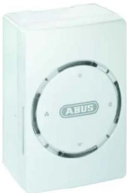
ABUS 4-channel video storage TVVR35000
natural_image
White rectangular electronic device labeled 'ABUS' with circular control panel (no additional text or symbols visible)User manual
Version 1.0
CE
English
These user manual contains important information for installation and operation.
This should be also noted when this product is passed on to a third party.
Therefore look after these operating instructions for future reference!
A list of contents with the corresponding page number can be found in the index.
i
Pay attention to the information in the separate quick guide.
Device overview
Status LED

- Power LED
- Network LED
- Data storage LED
- WLAN LED
Overview
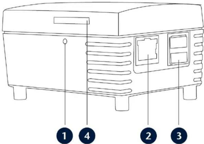
- Reset button: Restart system
- LAN: RJ45 connection (for connecting to a network)
- USB ports: for USB 2.0 devices (e.g. external HDD)
- SD card: SD slot for an SD card, max. 32 GB
Device overview ....3
Quick guide....7
Before you start....7
Establishing the connections 7
Configuring the device 7
Important safety information....8
Explanation of symbols....8
Proper use 8
General information 8
Power supply 8
Overloading / overvoltage 9
Cables 9
Installation location/operating environment 9
Care and maintenance....10
Accessories....10
Putting into operation....10
Children and the device....10
Introduction 11
General information ....11
Unpacking the device....11
Scope of delivery 11
System operation....12
Connections....12
Starting the device 12
Status LED 12
Setting up a connection....13
Setting up the system ....13
Login ....13
Installing the plug-in....14
Live image....15
Overview 15
Camera view 15
Favourites view....15
Operating mode 16
Manual recording (Panic Record) 16
Camera control 16
Using the numeric field ....17
Camera selection....17
Saving camera positions (presets) 17
Relays 17
Switching the image geometry....18
Activating and deactivating the cameras....18
Favourites ....19
Playback....20
Overview 20
Presentation view....20
Time stream....20
Playback bar 21
Export....22
Configuration....23
Camera 23
Setting up an IP camera 23
Deleting an IP camera 24
Extended mode....24
I/O module....25
I/O module 25
Overview 25
Settings 25
Drive 26
Drive 26
SD card, USB-1 and USB-2....26
Actions....27
Actions 27
Overview 27
Recordings 27
Creating a schedule....28
Deleting a schedule 28
Changing a schedule 28
Notifications 29
Commands....30
Storage....31
Network....32
Overview 32
General 32
LAN 33
WLAN 33
E-mail....34
Ports....35
Security 36
Security 36
Permissions 36
User....37
Other....38
Other 38
Date/Time....38
Firmware update 39
Safe mode....39
Troubleshooting....40
Device cleaning and care 41
Note......41
Disposal 41
Information on the EU directive on waste electrical and electronic equipment 41
Information on the European RoHS directive 41
GPL licence information....41
Technical data....42
Quick guide
Before you start
The following preparatory steps must be made:
- Pay attention to the general information, safety information and notes on setting up and connecting the device (see page 8 - 12).
- Check the contents of the package for completeness and damages.

Note
Pay attention to the information in the separate quick guide.
Establishing the connections

Note
Pay attention to the minimum radius when laying cables. Do not kink the cable.
- Connect the network cameras and the LAN connection on the device to the network.
- Set up the connection to the mains power supply, the Power LED lights up.
Configuring the device

Note
Pay attention to the information in the separate quick guide.
- You must configure the following settings in sequence:
- Camera
- I/O module
- Drive
- Actions
- Network
- Security
- Other
Important safety information
Explanation of symbols
The following symbols are used in this manual and on the device:
Symbol
Signal word Meaning


Warning Indicates a risk of injury or health hazards.
Warning Indicates a risk of injury or health hazards caused by electrical voltage.


Important Indicates possible damage to the device/accessories.
Note Indicates important information.
The following labels are used in the text:
Meaning
- ... Set of tasks or instructions with a defined sequence in the text
- ... Set of points or warnings without a defined sequence in the text
- ...
Proper use
Only use the device for the purpose which it was designed and built for. Any other use is considered inappropriate.
This device may only be used for the following purpose(s):
- This 4-channel video storage is used in combination with connected video signal sources (IP cameras) for object surveillance.
i
Note
Data storage is subject to national data-protection guidelines.
During installation, inform your customers regarding the existence of these guidelines.
General information
Before using the device for the first time, read the following instructions carefully and pay attention to all warnings, even if you are already familiar with electronic devices.

Warning
All guarantee claims become invalid for damages caused by non-compliance with these operating instructions.
We cannot be held liable for resulting damages.

Warning
We cannot be held liable in the event of material or personal damage caused by improper operation or non-compliance with the safety information.
All guarantee claims are invalid in such cases.
Keep this manual in a safe place for future reference.
If you pass on or sell the device, you must also include this user manual.
This device has been manufactured in accordance with international safety standards.
Power supply
- Only operate this device through a power source which supplies the mains power specified on the type plate.
- If you are unsure of the power supply at the installation location, contact your power supply company.

Warning
Avoid data loss!
Always use an uninterruptible power supply (UPS) with overvoltage protection.
- Disconnect the device from the mains power supply before carrying out maintenance or installation work.
- To disconnect the device completely from the mains power supply, the plug must be disconnected from the mains socket. Therefore, the device should be positioned so that direct and unobstructed access to the mains socket is guaranteed at all times and the plug can be disconnected immediately in an emergency.
- To avoid the possibility of fires, the plug should always be disconnected from the network socket if the device is not used for long periods. Disconnect the device from the mains power supply before impending electrical storms, or use an uninterruptible power supply.

Warning
Never open the device on your own! There is a risk of electric shocks! If it is necessary to open the device, consult trained personnel or your local maintenance specialist.
Overloading / overvoltage
- Avoid overloading of mains sockets, extension cables and adapters as this can result in fires or electric shocks.
- Use overvoltage protection to prevent damages caused by overvoltage (e.g. electrical storms).
Cables
- Always hold cables by the connector, and do not pull the cable itself.
- Never touch the mains cable with wet hands, as this can lead to a short circuit or electric shock.
- Never knot the cable, and do not tie it to other cables.
- All cables should be laid so that they cannot be stepped on or cause an obstruction.
- A damaged mains cable can cause a fire or electric shock. Check the mains cable from time to time.
- Never modify or manipulate the mains cable or plug.
- Do not use plug adapters or extension cables that do not conform to the applicable safety standards, and do not make alterations to power supply cables or mains cables.
Installation location/operating environment
- Position the device on a firm, level surface and do not place any heavy objects on the device.
- The device is not designed for operation in rooms subject to high temperatures or moisture (e.g. bathrooms), or in excessively dusty rooms.
- Operating temperature: 5 °C to 35 °C. The device may only be operated in moderate climate conditions.
Ensure the following:
- The device must not be exposed to direct heat sources (e.g. heaters);
- The device must not be exposed to direct sunlight or strong artificial light;
- The device must not be placed in close proximity to magnetic fields (e.g. loudspeakers);
-
Naked flames (e.g. candles) must not be placed on or near the device;
-
Contact with spraying or dripping water and aggressive liquids must be avoided;
- The device must not be operated in close proximity to water, and must not be submerged under any circumstances (do not place objects containing water on or near the device, such as vases or drinks);
- Foreign objects must not penetrate the device;
- The device must not be exposed to strong variations in temperature, as this can lead to condensation and electrical short circuits.
- The device must not be exposed to excessive jolts or vibrations.
Care and maintenance
Maintenance is necessary if the device has been damaged. This includes damage to the plug, mains cable and housing, penetration of the interior by liquids or foreign objects, exposure to rain or moisture or when the device does not work properly or has fallen.
- Disconnect the device from the mains power supply before maintenance (e.g. cleaning).
- If smoke develops or unusual noises or odours are detected, then switch off the device immediately and pull the mains plug from the socket. In such cases, the device should not be used until it has been inspected by a qualified technician.
- Maintenance work should only be carried out by qualified specialists.
- Never open the housing on the device or accessories. There is a risk of fatal injury due to an electric shock when the housing is opened.
- Clean the device housing and remote control with a damp cloth.
- Do not use solvents, white spirit or thinners as these can damage the surface of the device.
- Do not use any of the following substances:
- Salt water, insecticides, solvents containing chlorine or acids (ammonium chloride) or scouring powder.
- Gently rub the surface with a cotton cloth until it is completely dry.

Warning
The device works under dangerous voltages. The device must only be opened by authorised specialists. All maintenance and service work must be carried out by authorised firms. Improper repairs can expose device users to the risk of fatal injury.
Accessories
- Only connect devices that are suitable for the intended purpose. Otherwise, hazardous situations or damage to the device can occur.
Putting into operation
- Observe all safety and operating instructions before putting the device into operation for the first time.

Warning
When installing the device in an existing video surveillance system, ensure that all devices are disconnected from the mains power supply and low-voltage circuit.

Warning
If in doubt, have a specialist technician carry out assembly, installation and connection of the device.
Improper or unprofessional work on the mains power supply or domestic installation puts both you and other persons at risk.
Connect the installations so that the mains power circuit and low-voltage circuit always run separately from each other. They should not be connected at any point or become connected as a result of a malfunction.
Children and the device
- Do not allow children access to electrical devices. Never allow children to use electrical devices without supervision. Children may not be able to accurately detect possible risks. Small parts can be life-threatening if swallowed.
- Keep batteries away from small children. Call for medical assistance immediately if a battery is swallowed.
- Keep packaging materials away from children (danger of suffocation).
- This device should not be used by children. If used improperly, spring-loaded parts can be ejected and cause injuries to children (e.g. eye injuries).
Introduction
Dear customers,
Thank you for purchasing this product.
This product complies with current domestic and European regulations. Conformity has been proven, and all related certifications are available from the manufacturer on request (www.abus-sc.com).
To maintain this status and to guarantee safe operation, it is your obligation to observe these operating instructions!
Read the entire operating manual carefully before putting the product into operation and pay attention to all operating and safety information!
All company names and product descriptions are trademarks of the corresponding owner. All rights reserved.
In the event of questions, please contact your local maintenance specialist or dealer.

Disclaimer
These operating instructions have been produced with the greatest care. Should you discover any missing information or inaccuracies, please contact us under the address shown on the back of the manual. ABUS Security-Center GmbH does not accept any liability for technical and typographical errors, and reserves the right to make changes to the product and operating instructions at any time and without prior warning. ABUS Security-Center GmbH is not liable or responsible for direct or indirect damages resulting from the equipment, performance and use of this product. No forms of guarantee are accepted for the contents of this document.
General information
In order to use the device correctly, read this user manual carefully and keep it in a safe place for later use.
This manual contains instructions on 4-channel video storage operation and maintenance.
Consult an authorised specialist if the device needs to be repaired.
Unpacking the device
Handle the device with extreme care when unpacking it.
The packaging is made of reusable materials, and should always be passed on for recycling.
We recommend the following:
Paper, plastic packaging, cardboard and corrugated cardboard should be disposed of in the appropriate recycling containers.
If recycling containers are not available in your local area, then you can dispose of these materials as domestic waste.
If the original packaging has been damaged, inspect the device. If the device shows signs of damage, then return it in the original packaging and contact the manufacturer.
Scope of delivery
- 4-channel video storage
- Quick Guide
- Manual on CD
- 1,8 m Power cable
• 1,5 m network cable
• EU-Plug - UK-Plug
- AUS-Plug
System operation
Connections

Note
See the overview on page 4.
| No. | NameFunction |
| 1 | Reset button:• The system is restarted |
| 2 | LAN:• RJ45 connection (for connecting to a network) |
| 3 | USB ports:• For external USB 2.0 devices (e.g. external HDD) |
| 4 | SD card:• Max. 32 GB |
Starting the device

Important
The device must only be connected to the mains voltage supply specified on the type plate.
For safety reasons, use an uninterruptible power supply (UPS).
When the device is connected to the power supply, the Power LED lights up in green.
If the device has been started correctly, the LEDs no. 2–4 flash 3 times in total.
Status LED

Note
See the overview on page 3.
| No. | State | Function |
| 1 Green System status is OK | ||
| 2 Green | Off | Network connectedNetwork not connected |
| 3 Green | Off | Data storage activeData storage inactive |
| 4 Blue | Green | WLAN activated and network connectedWLAN activated and network not connectedWLAN deactivated |
Setting up a connection
Setting up the system
Install and start the "IP Installer" on the enclosed software CD.

Click "Search" – the program will search the network for any connected NAS devices.
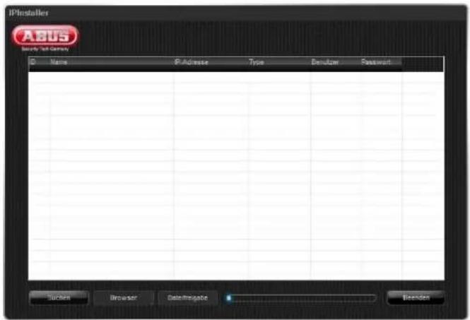
Once the search is finished, you will be shown a list of devices found in the network. When you double-click a list entry, a connection to the video buffer is set up.
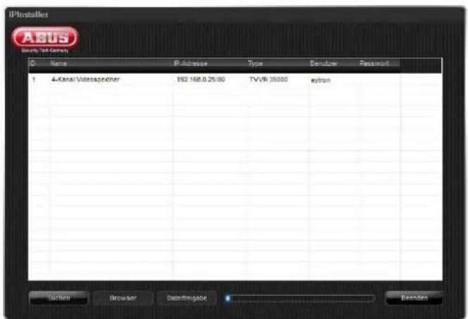
Login
Select your preferred language. Enter "eytron" in the "User name" field.

If you are using MS Internet Explorer 8, you are requested to select the display procedure to be used. Two options are available:
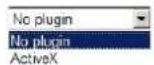
If you want to use the standard display procedure, you select "No plug-in" in the selection box and the desired user by clicking on the key switch. For this procedure, no installation on the client PC is required.
If you want an improved presentation of the live images, you must install the browser enhancement (ActiveX plugin). Using this plug-in, the application can display the live images in the MPEG-4 compression method. The advantages of this method are more fluid presentations and improved quality for the live images.
On the login screen, select the ActiveX display method and login to the system by clicking the key switch.
i
Note
The ActiveX plug-in can only be used for connections to the local network. It cannot be sued for connections from the Internet or from subnets via a router, and no selection options will be provided for the user.
Installing the plug-in
When a camera is activated for the first time, you are requested to install the required plug-in for your web browser.
MS Internet Explorer 8:
Click on Install - the installation of the plug-in starts.

When the plug-in has been installed successfully, the camera is displayed by ActiveX.
In some cases, the execution of the plug-in may be blocked by Internet Explorer (IE8).

Then the security settings must be modified in the Internet options (Extras menu → Internet options).
Select the Security tab page, then click on the Custom level button.
In the list in the dialog that appears, change the item "Initialize and script ActiveX controls not marked 'Safe for scripting'" from the deactivated to the activated state. Close all the windows again using OK.

Now the browser must be closed and restarted. The plugin can now be used.
Firefox 3.6, Chrome 4.1 and Safari 5:
Install the QuickTime plug-in on the enclosed software CD.
The same plug-in is used for all three browsers.
When the plug-in has been installed successfully, the camera is displayed by the QuickTime plug-in.
Live image
Overview
The live view starts automatically after the login.

The screen header contains the following menus:
- Logout
Click on "Logout" to log out of the system.
- Settings
Click on "Settings" to go to the device menu.
- Support
Click on "Support" to go to the online help.
The system status, date and time are displayed on the top right.
Status symbols
- The following symbols are displayed depending on the operating status of the device:
| Symbol | Meaning |
 | AlarmLights up when a video signal from an IP cam-era is lost. |
 | RecordingLights up when video data from at least one camera is recorded. |
| [SSAK] | MalfunctionLights up if a fault occurs, e.g. HDD problem. |
Camera view
natural_image
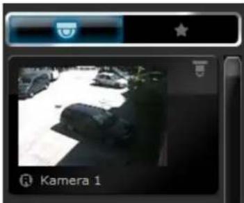
Camera 1 interface showing a black-and-white photo of a parked car on a paved surface (no text or symbols visible)Here, all the activated cameras are listed in a slide view. The camera type is indicated by the camera symbol on the top right-hand side of the slide. This can vary as follows:
- Pan/tilt camera with network connection
• Network camera or video server
The camera name is always displayed at the bottom of the slide.
If the camera is recording, the Record symbol appears on the slide.
Favourites view

All the favourites stored are displayed here. This is indicated by the favourites symbol.

Note
For more information, see page 19.
Operating mode
A basic distinction is made between two categories:
| Symbol | Meaning | |
 | Live mode | |
 | Playback mode | |
The live mode is used for viewing what is currently being monitored by the system's cameras.
The playback mode is used to access the video data recorded by the individual cameras.
i
Note
For more information on the playback mode, see page 20.
Manual recording (Panic Record)
Activating the Manual Recording button ensures that recordings are made from all the currently activated cameras. The recording continues until the button is deactivated again.
It is then possible to watch the recordings in Playback mode.
| Symbol | Meaning | |
 | Manual recording ON | |
 | Manual recording OFF | |
Camera control
The operating panel on the lower right-hand edge of the screen is used to control pan/tilt cameras.
| Symbol | Meaning | |
 | You click on the desired direction button to control the camera accordingly. | |
 | The current image area can be enlarged using the zoom function. | |
To direct a camera, left-click that camera's live image in the live window section.
However, only the camera currently selected can be directed in this way.
Alternatively, the camera can be selected by means of the numeric field. For this, the number of the camera to be activated must be entered.
If a pan/tilt camera has been selected, the camera's analogue zoom is used. With fixed cameras, the image is zoomed in on digitally.
i
Note
For an analogue camera with a zoom objective, when used in connection with a video server, the camera's analogue zoom is used.
Using the numeric field
The numeric field can be divided into three separate operating modes:
- Camera selection
- Presets
- Relays
The current selection is shown in an LCD display.

| Symbol | Meaning |
| Camera selection | |
| Presets(stored camera positions) | |
| Relays | |
| Pan/tilt camera returns to the starting position | |
| Reset input mode to two-digit(max. entry 99) | |
| Number keys |
Camera selection
If the camera selection symbol is activated, the number key can be used to include a camera directly in the live image.

In this example, number key 1 was clicked, and camera 1 was directly included in the live image.
Saving camera positions (presets)
The presets can be used to save and call up specific camera positions for pan/tilt cameras. Presets are saved by pressing and holding down a number key on the keyboard while the preset mode is activated. You then receive confirmation on the live image of the relevant camera (e.g. Preset 1 has been set).
When saving more than nine presets, you first have to switch the preset input to the two-digit mode using the
-- button. The preset is then saved by pressing and holding down the number key after entering the second digit.
Example for saving preset 14:
| No. | Symbol | Meaning | |
| 1 |  | Activate pan/tilt cam-era | |
| 2 |  | Define image area | |
| 3 |  | Switch keyboard to preset mode | |
| 4 |  | Activate two-digit mode | |
| 5 |  | Enter first digit | |
| 6 |  | Enter second digit and hold down key | |
| 7 | PtZ Preset 1 was saved | Confirmation of saved preset | |
Relays
Here you can control relays directly from the cameras set up or from a video server.
Click on the symbol for relays and select the relevant allocated digit for the relay. When you click on the digit, the corresponding relay is switched on for the camera or the video server.
Switching the image geometry
The camera puck + can be used to represent a total of 3 different views.
The views are only switched once the mouse button is released.
The following is a more detailed description of how to use the camera puck.

The camera puck is used to increase or decrease the number of camera windows. For example, if more free camera places are required, the puck must be moved along the horizontal plane towards the plus sign (in quadratic view).
If the puck is moved along the vertical plane, the current view is changed to the 1Plus view. The further the puck is moved away from the top left-hand corner, the larger the 1Plus window.
If more free windows are required again in this view, they can be created by moving the puck along the horizontal plane (+/-).
Activating and deactivating the cameras
Drag and drop a camera into a free live window to activate (switch on) the camera.
To do this, switch to the live mode (No. 1). Next, move the view switch to the camera view (No. 2).
In the Camera view, click the slide of the desired camera and hold down the left mouse button (No. 3).
Now move the mouse to a free camera window and release the left mouse button (No. 4). The camera is then embedded in the desired window.
If you wish to embed the camera in another window, you can again use the drag and drop function to move the embedded live image to another window.
To deactivate (switch off) a camera, simply release the camera outside the chrome frame using drag and drop (No. 5). We recommend dragging the camera back to the slide list.
Example of activating a camera:
| No. | Symbol | Meaning | |
| 1 | Select the live mode | ||
| 2 | Select the camera view | ||
| 3 |  | Select a slide and hold down the left mouse button | |
| 4 |  | Select a free camera window and release the left mouse button | |
| 5 |  | Deactivate camera | |

Note
When activating it for the first time, please see the notes on installing a plug-in for your web browser on page 14.
Favourites
When using multiple cameras, it is advisable to save certain camera views as favourites.
To display the cameras again, only the favourite needs to be activated instead of each individual camera. Another advantage is that the image geometry currently set is also saved when a favourite is created. This means there is no need for manual switching between the views.
We differentiate between 3 favourite types:
• Live favourite
- Playback favourite with bar display
- Playback favourite with full-screen display
| Symbol | Meaning |
 | Live favourite |
 | Playback favourite with bar view |
 | Playback favourite with full-screen database playback |
Depending on the operating mode in which the favourite was created, that mode is restored when the favourite is activated.
Example for creating and deleting a favourite in the live mode:
| No. | Symbol | Meaning | |
| 1 |  | Switch the operating mode to the live mode | |
| 2 |  | Set the desired image geometry | |
| 3 | 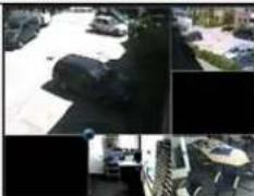 | Activate the desired cameras and define the sequence in the live window | |
| 4 |  | Switch the view switch to the Favourites view | |
| 5 |  | Create a new favourite | |
| 6 |  | Assign a name for the favourite to be saved, and confirm with OK | |
| 7 |  | New favourite is displayed as slide (wrong image) | |
| 8 |  | Delete the selected favourite | |
When this slide is dragged into the live window, the image geometry is changed according to the saved view, and the cameras are displayed in the corresponding sequence. In the process, the existing cameras are replaced.
i
Note
Favourites are created separately for each user. This means that favourites cannot be seen by other users when in multiple-user mode. No supervisor rights are needed for the creation of favourites.
i
Note
The procedure for creating a favourite applies in the same way to the playback favourite with bar view and the playback favourite with full-screen database playback.
Playback
Overview
Click on the playback symbol to go to the playback mode.

When switching to playback mode, the keyboard at the lower edge of the screen is replaced by the playback controls. A time stream is also added to the interface, which is used for selecting when playback starts and for defining the backup space.
If you have switched to the playback mode, all the camera fields that can be used are empty. To start a play-back, you first have to activate the camera to be played back in one of the fields.
The process here is the same as for activating/deactivating the cameras in the live mode.
If any cameras are already activated when the system switches to database playback, these cameras are used for playback (synchronous playback).

Note
For more information on creating archives, see page 31.
Presentation view
There are two different presentation views in the play-back mode:
| Symbol | Meaning |
 | Playback in bar view |
 | Playback with full-screen database playback |
The bar view is used to present the current recording. Here we differentiate between the following colours:
| Symbol | Meaning |
 | Continuous recording (yellow bars) |
 | Activity recognition (grey bars) |
 | External data (copper-coloured bars) |
Time stream
The time stream enables quick access to the saved video data.
Explanation of the time stream:
| Wacha | No | D | W | Op | F | S | So |
| 24.08.2013 11:54:00 | 08.09.2013 11:54:00 | ||||||
| Symbol Meaning | |
 | Backup period |
 | Slider for start time |
 | Navigating on the time stream |
 | View switch |
You can click on and pull the blue bar to select your backup period.
The slider for the start time specifies the absolute start time. If the start time is to be a certain date or time, the slider must be set to the desired starting position by clicking and dragging with the mouse. Please note that you may have to first switch to a higher-level view (e.g. month or day) to select the starting point.
The view switch on the left-hand side of the time stream is used for switching the current playback period. It can be switched between year, month, week, day, hour or minute. Depending on the position of the slider, the time stream caption (units) is changed accordingly.
You can select the backup period directly using the calendar button.
Open the calendar by clicking the calendar button in playback mode.

After the day is selected, the view window automatically changes to the day view, and existing data for cameras can be exported.
Playback bar
Once you have made all the settings, you can play back the selected cameras using the Forward and Reverse buttons.
The meaning of the individual playback buttons is explained in the following:
| Symbol | Meaning |
 | Jump to previous event |
 | One frame backwards |
 | Reverse playback |
 | Forward playback |
 | One frame forwards |
 | Jump to next event |
The speed controller can also be used to set the
playback speed to between 0.125x and 8x.
If you hold down the one frame Forwards or Backwards button, the video is automatically played back until you release the button again.

Note
If no recording exists for the selected period, a blue image with the caption "No video" is displayed instead of the video image.
Export
You have the option to save a single frame or video data. Saving video data:
| Pos. | Meaning |
| 1 | Switch to the playback mode |
| 2 | Select a camera using drag and drop |
| 3 | Select the period to be backed up |
| 4 | Click on  |
| 5 | A download window opens |
| 6 | Click on “Save” |
| 7 | Select a storage location |
| 8 | Click on “Save” again |
The video data recorded can be played back with any standard media player. If your program has difficulties playing the data, check that the corresponding codecs (MJPEG, MPEG-4, H264) is installed.
Saving a single frame:
| Pos. | Meaning |
| 1 | Switch to the playback mode |
| 2 | Select a camera using drag and drop |
| 3 | Select the image using the slider |
| 4 | Click on “Image export” |
| 5 | A download window opens |
| 6 | Click on “Save” |
| 7 | Select a storage location |
| 8 | Click on “Save” again |
You can now print out the single image or send it by e-mail.
Repeat the above steps to save additional video data or individual images.
Configuration
Camera
Click on "Settings" at the top left to go to the configuration menu. Select the Camera button.
A completely configured camera (user name, password and a valid IP address) is necessary for successfully setting up an IP camera.
Otherwise, configure the camera according to the camera documentation until access over a web browser is possible.
For the first access, no cameras are set up yet.
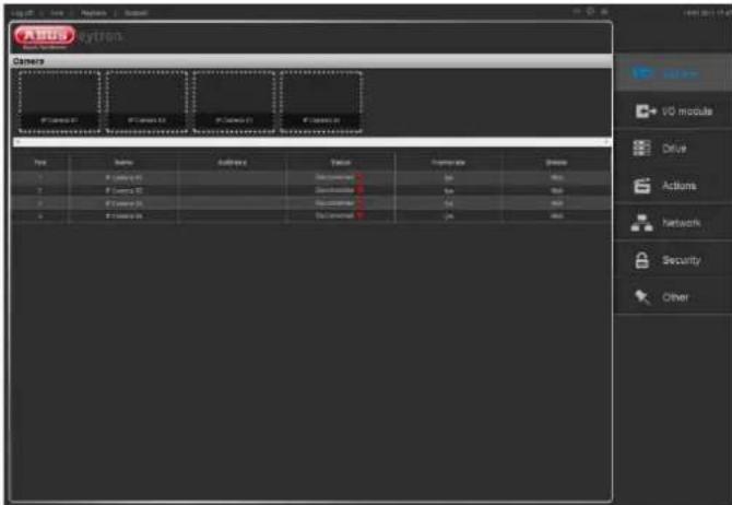
If a camera is set up, it is listed in the overview and you can see a preview image in the preview bar.
Explanation of the overview:
| Text | Meaning |
| Name | Name of your IP camera |
| Address | Address of your IP camera |
| Status | Green → connectedRed → disconnected |
| Frame rate | Frame rate currently set |
| Bit rate | Bit rate amount |
Setting up an IP camera
In the camera overview, click on an empty preview image to include a new camera.
This takes you directly to the settings for the new camera.

Steps for setting up a camera:
| Pos. | Meaning |
| 1 | Tick the “Activate camera” box |
| 2 | Click on search the network for the available camerasThe drop-down menu provides you with a list of the cameras foundSelect an IP address for your camera |
| 3 | Enter a name for the camera in the “Name” field |
| 4 | The camera type is included automatically |
| 5 | If a user name and password have been configured in the camera for access, they must be entered in the “User name” and “Password” fields |
| 6 | Select the “Permanent” button to set up permanent recording for your camera |
| 7 | Select the “Activity” button for your camera to record when it detects activity |
| 8 | Select the “Event” button to record for an external eventIn the drop-down menu, select a digital input to be evaluated |
| 9 | Now click on “Save” |
When you select a recording type, a schedule is automatically created and linked to the selected camera.
You also have to assign a storage drive to the selected camera in order to be able to record video data – see page 33.
Your camera is now configured for live image presentation, and a preview image appears in the slide bar.

Note
To be able to set up activity detection, you must ensure that the activity detection is activated within the camera. You will find more information on this in the instructions for the camera.
Deleting an IP camera
To delete a camera from the configuration, proceed as follows:
| Pos. | Meaning |
| 1 | Select the camera to be deleted in the preview bar |
| 2 | Remove the “Activate camera” checkmark |
| 3 | Click on “Save” |
| 4 | Your camera has now been deleted from the configuration |
i
Note
If you want to include the deleted camera in the system again, you have to enter all the parameters for your camera again.
Extended mode
Click on the "Extended mode" button
A menu opens for changing the settings for stream 1 and stream 2.
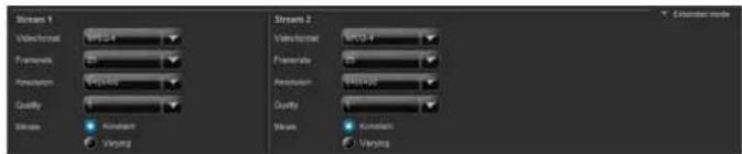
Here you now have the option to set up stream 1 and stream 2 separately.
Settings for a stream:
| Pos. | Meaning |
| 1 | Select the video format |
| 2 Select the frame ratein images per second | |
| 3 | Select a resolution |
| 4 | Select the settings for the quality of the video stream |
| 5 | Select the “Constant” bit rate→ The video quality can vary according to the level of activity |
| 6 | Select the “Variable” bit rate→ Constant video quality |
| 7 | Activate audio→ The audio function of the camera is used |
| 8 | Now click on “Save” |
i
Note
If the bit rate is set to "Variable" for all the cameras, there is a risk that the network bandwidth will not be sufficient to transmit all the connected cameras with the same level of quality.
When you click "Save", the changed settings are automatically sent to the camera.
I/O module
I/O module
Click on "I/O module" to go to the I/O module overview.

The I/O module is divided into the following subsections:
- Overview
- Settings
Click on a symbol to go to the settings.
The I/O module is used to include the IP relays and IP inputs of cameras.
Overview
Here you see a summary of the status of your I/O detectors.

Explanation:
| Text | Meaning |
| Name | Name of the input or output |
| Type | Input or output |
| Status | Connected or disconnected |
| Alarm | Yes or no |
Settings
All the connected cameras are displayed here that have a digital input/output.
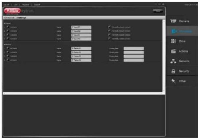
Explanation of the setting options:
| Text | Meaning |
| IP input | All the digital inputs for the connected cameras are listed here |
| Activate | Set the “Activate” checkbox to be able to use the digital input |
| Name | Enter a name |
| Opener | Not activated: The input works as a closer. That is, the standard setting is that it is openActivated: The input works as a closer. That is, the standard setting is that it is closed |
| IP relays | All the digital outputs for the connected cameras are listed here |
| Activate | Set the “Activate” checkbox to be able to use the digital output |
| Name | Enter a name |
| Closing time | Enter a closing time in seconds→ Period for which the relay remains closed after being used |
| Save | Click on “Save” to accept the settings. |

Note
You can now use the digital inputs and outputs for commands and messages – see pages 29 - 30.
Drive
Drive
Click on "Drive" to go to the drive overview.
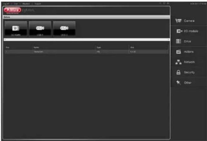
The overview is divided into the following subsections:
- SD card
- USB-1
- USB-2
Click on a symbol to go to the settings.
i
Note
When you format the drive, all the data located on it is lost forever.
i
Note
If you remove the drive before "Disconnecting" it first, you risk losing data.
You can only assign one drive usage to a drive.
- Storage drive Drive is only used for storing video data.
- Backup drive → Drive can only be used for backing up video data.
SD card, USB-1 and USB-2

You have the following options for configuring the drive:
| Pos. | Meaning |
| 1 | Select a drive → it is coloured blue in the preview |
| 2 | Set the checkmark in “Use drive” |
| 3 | Select the drive usage:Storage driveBackup drive |
| 4 | Displays the currently selected size and the total size of the drive |
| 5 | In “VMS usage” you can reserve storage space for the VMS on the drive |
| 6 | Click on “Format drive” to format the driveWhen the formatting is completed, you receive a message about how the formatting procedure went |
| 7 | Click on “Show contents” to view the contents of the drive |
| 8 | To be able to remove the drive, click on “Disconnect drive”You receive a message stating that you can now remove the drive |
i
Note
When using the drive for the first time, format it.
Actions
Actions
Click on "Actions" to go to the actions overview.

The overview is divided into the following subsections:
- Overview
- Schedule
- Notifications
- Commands
- Storage
Click on a symbol to go to the settings.
Overview
In the overview menu, you see a summary of the actions currently set up for your cameras.

If no actions are set up yet, the overview menu is empty.
Explanation of the overview menu:
| Text | Meaning |
| Name | Name of your IP camera |
| Schedule | Schedule set up: yes / no |
| Recording | Recording: yes / no |
| Command | Which command is set up |
| Message | Which message is set up |
Recordings
In the recordings menu, you see the schedule set up for your camera. Under the menu item "Set up IP camera", the recording type has already been defined. On this screen, permanent recording was selected.

In the standard setting, the entire recording period is selected. With this setting, recording takes place every day from 0:00 – 23:59.
You can set up schedules based on 15 minute periods. The coloured representation of the different recording types and possible combinations is explained as follows:
| Symbol | Meaning |
| Permanent recording | |
| Activity detection | |
| Event recording | |
| Permanent recording and activity detection | |
| Permanent and event recording | |
| Activity detection and event recording | |
| Permanent, activity and event recording |
Creating a schedule
To create an individual schedule, proceed as follows:
| No. | Symbol | Meaning | |
| 1 |  | Select a camera in the preview bar | |
| 2 | 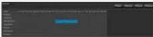 | Click on the desired starting time and keep the left mouse button pressed. Select the desired area.(10.00 – 16.00) | |
| 3 | 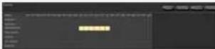 | Click on the type of recording you want (permanent recording) | |
| 4 | Click on “Save” | ||
If you want to select a whole day, click on the weekday you want.
To select a specific period for the entire week, click on the corresponding time.
Deleting a schedule
To delete the schedule, proceed as follows:
| No. | Symbol | Meaning |
| 1 |  | Select a camera in the preview bar |
| 2 | 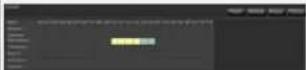 | Select the period you want to delete |
| 3 | 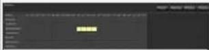 | Click on “Delete” |
| 4 | Click on “Save” |
Changing a schedule
To change the schedule for your recording, proceed as follows:
| No. | Symbol | Meaning |
| 1 |  | Select a camera in the preview bar |
| 2 |  | Select the period you want to change |
| 3 |  | Click on the type of re-cording you want to add (activity detection) |
| 4 | Click on “Save” |
You can set up the schedule to meet your requirements. Up to 3 recording types are possible at the same time.
Notifications

Here you can set up up to 3 notifications for each camera.
A notification can be triggered by:
- Movement (IP MD)
→ The notification is triggered if the camera detects movement - I/O (IP Input)
→ The notification is triggered if a digital input is activated on the camera - Camera disconnected
→ If the network connection for the camera is interrupted, the notification is triggered
The following destinations can be set:
- Text message to an e-mail address
- Text message to the browser
- Text message to a VMS station (software)
Under the "E-mail" menu item, you have the option of sending a text message to an e-mail address.
| Pos. | Meaning |
| 1 | Enter the destination address |
| 2 | Text → Enter a text to be sent with the e-mail |
Set the "Attach camera picture" checkbox to send a current image with the e-mail.
Under the "Browser" menu item, you have the option of sending a text message to the browser.
| Pos. | Meaning |
| 1 | Enter a text that you want to appear in the browser |
Under the "Software" menu item, you can send a message to the VMS that will appear in the live image there.
| Pos. | Meaning |
| 1 | Enter the address of the VMS station |
| 2 | Text → Enter a text to be sent to the VMS station |
To complete your configuration, please click on "Save".
Example for setting up a notification:
Camera 1 is to send an e-mail if movement is detected.
| Pos. | Meaning |
| 1 | Select camera 1 in the preview bar |
| 2 | Tick the “1. Activate Message” checkbox |
| 3 | Select the “IP MD 1” menu item |
| 4 | Select the “E-mail” menu item |
| 5 | Enter an e-mail address |
| 6 | Enter a text to be sent with the e-mail |
| 7 | Click on “Save” |
If camera 1 detects movement, an e-mail is now sent with the text entered.
i
Note
To be able to set up this command, you must have set up movement detection in the camera. In addition, a valid e-mail address must be set up – see page 34.
Commands

Here you can set up up to 3 commands for each camera.
The following commands are available:
- Go to preset
- Start tour
- IP Relais
Under the "Event" menu item, you can set when a command is to be triggered.
| Pos. | Meaning |
| 1 | Select a camera in preview bar |
| 2 | Tick the “1. Activate Command” checkbox |
| 3 | Select “IP MD”, “IP Input” or “Camera separately” |
Under the "Command" menu item, you can set which type of command is to be executed.
| Pos. | Meaning |
| 1 | Select “PTZ-Position”, “PTZ Tour”, “Relay Level” or “Relay Edge” |
Level:
When the relay contact is used with level control, the contact remains closed until opened manually by the user.
Edge:
When the relay contact is used with edge control, the contact remains closed until the set hold time has elapsed.
Under the "Selection" menu item, you can set which preset is to be used, which tour started, or which relay switched.
| Pos. | Meaning |
| 1 | Select a preset position, a tour or a relay. |
To complete your configuration, please click on "Save".
Example for setting up a command:
Camera 1 is to go to preset position 1 if movement is detected.
| Pos. | Meaning |
| 1 | Select camera 1 in the preview bar |
| 2 | Tick the “1. Activate Command” checkbox |
| 2 | Select the “IP MD 1” menu item |
| 3 | Select the “PTZ-Position” menu item |
| 4 | Select the “Preset position 1” menu item |
| 5 | Click on “Save” |
Now camera 1 will go to preset position 1 if movement is detected.
i
Note
To be able to set up this command, you must have set up movement detection in the camera. In addition, preset position 1 must be stored.
Storage
In the storage menu, you can enter settings for creating an archive and assign a storage drive to the camera.
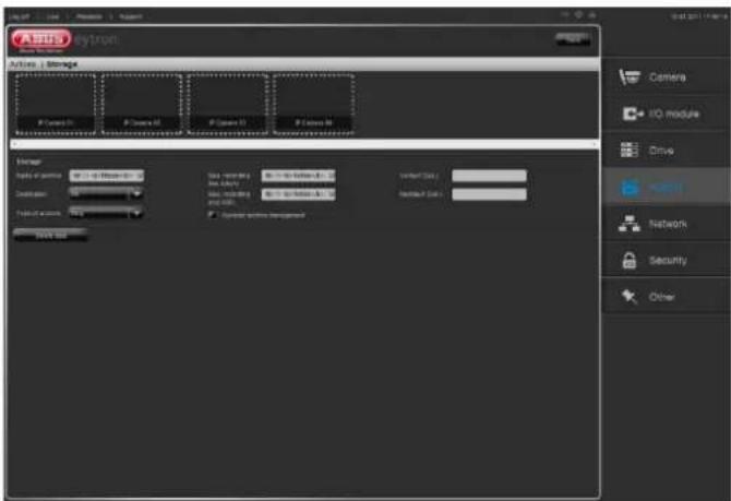
Archives are used to store video data.
We differentiate between the following archives:
- Ring archive
- Alarm archive
Ring archive:
When the ring archive is completely full, the oldest video data is automatically overwritten.
Alarm archive:
This archive can only be filled with video data once. Further image data is then ignored until the user has manually deleted the memory.
Enter the lead or lag time in seconds (max. 60 seconds), in order to record data before or after the alarm in the case of an alarm.
Click on "Delete data" to delete the archive manually.
Tick the "Dynamic archive management" checkbox.
With this setting, the stored video data is overwritten as soon as the max. memory size of the archive has been reached.

Note
Please see the information on including a drive on page 25.
Procedure for setting up an archive:
| Pos. | Meaning |
| 1 | Select a camera |
| 2 | Enter an archive name |
| 3 | Select an archive destination |
| 4 | Select the archive type |
| 5 | Enter either a max. recording time or a max. recording size for which the archive is to be used |
To complete your configuration, please click on "Save".

Note
To be able to select a storage drive, you have to set this up first. See page 26.
Example for setting up an archive:
The archive is to have the following properties:
- Camera: camera 1
- Archive name: Test_1
- Destination: USB-1
- Archive type: ring archive
- Max. recording time: 7 days
| Pos. | Meaning |
| 1 | Connect the drive to USB-1 and declare it as a storage drive |
| 2 | Select camera 1 |
| 3 | Enter Test_1 as the archive name |
| 4 | Select USB-1 as the destination |
| 5 | Select ring archive as the archive type |
| 6 | Enter 7 for the max. recording time |
| 7 | Click on “Save” to accept the change |
You have now set up an archive for camera 1.
Network
Overview
Click on "Network" to go to the overview.
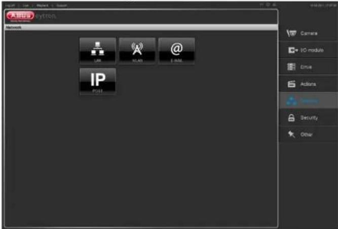
The overview is divided into the following subsections:
• LAN
- WLAN
- E-mail
- RTSP
Click on a symbol to go to the settings.
General
An overview of relevant terms when using the device in a network can be found below.
| Parameter Setting | |
| IP address An IP address is the unique address of a network device within a network.This address may only appear once within a network. Certain IP address ranges are reserved for public networks (e.g. the Internet). | |
| Subnet mask | A subnet mask is a bit mask used for making decisions and assignments during routing.255.255.255.0 is the standard subnet mask in home networks. |
| Gateway | A gateway is a network device which allows all other network devices to access the Internet.This can be the computer connected to the DSL modem or – usually – the router or access point within the network. |
| Name server | The name server is responsible for assigning a unique IP address to a web address or URL (e.g. www.google.de). Also known as DNS (Domain Name Server).When a domain name is entered into a browser, the DNS searches for the corresponding IP address of the server and |
| forwards the query on.The IP of the provider's DNS can be entered here. However, it is often sufficient to select the IP of the gateway. This then forwards the queries independently to the provider DNS. | |
| DHCP | The DHCP server automatically assigns the IP address, subnet mask, gateway and name server to a network device.DHCPs are available in current routers.The DHCP service must be specially set and activated (see the corresponding manual for more information).Note:When using fixed IP addresses and a DHCP server, make sure that the fixed IP addresses are outside the address range assigned by DHCP. Otherwise, problems could occur. |
| Port | A port is an interface used for communication by different programs. Certain ports are fixed (21: Telnet, 23: FTP), whilst others can be freely selected. Ports are important for different applications (e.g. external access to the device over a browser). |
| MAC address | The MAC address (Media Access Control or Ethernet ID) is the specific hardware address of the network adapter.This is used for the unique identification of the device in a computer network. |
| SSID | Service Set IdentifierCode to distinguish different WLAN networks |
LAN
You have to enter all the necessary parameters here for your device to function in the wireline network.
The standard setting is DHCP, so that you find your device when you first access the network.

Steps required for setting up LAN:
| No. | Text | Meaning |
| 1 | MAC address | Is determined automatically |
| 2 Obtain IP automatically | IP address is assigned dynamically via DHCP | |
| 3 Use the following settings | You can assign the following parameters manually | |
| 4 IP address | Address of the network device in the network (manual assignment) | |
| 5 Subnet mask | Enter your subnet mask (255.255.255.0 standard) | |
| 6 DNS server | Address of the Domain Name Server (usually the IP address of the gateway) | |
| 7 Gateway | Enter the address of the gateway for Internet access | |
Click on "Save" to accept the new settings.
WLAN
The 4-channel video storage features a WLAN network interface for wireless data transmission in an IP network.
The 4-channel video buffer must be connected via a network cable for the initial configuration of all WLAN parameters.

If you wish to configure the WLAN interface, proceed as follows:
| No. | Text | Meaning |
| 1 | WLAN | WLAN settings |
| 2 | Activate | Tick the “Activate” checkbox to switch on the WLAN |
| 3 | SSID | The drop-down menu provides you with a list of the networks foundSelect a network |
| 4 | WLAN mode Select the WLAN connection mode hereInfrastructure: The device is connected to a network via an access pointAd-hoc: A direct network connection is set up between two network devices(Peer-to-peer environment) | |
| 5 | Channel | Set the channel which the access point uses for transmission |
| 6 | Security | Setting for WLAN network security |
| 7 Encryption | You can set the encryption method for wireless transmission hereWEP: A 64 or 128 bit key is used for encryption. To communicate with other devices, these keys must be the same.WPA-PSK / WPA2-PSK: Dynamic keys are used for this method. TKIP or AES can be used as encryption protocols. |
| 8 Algorithm | Select the corresponding type of encryption.WEP: no selectionWPA-PSK / WPA2-PSK: TKIP or AES |
| 9 Key | Enter the network key |
| 10 IP address | Settings for the IP address |
| 11 Option 1: Obtain automatically | IP address is assigned dynamically via DHCP→ The following input fields are inactive, as they were obtained from DHCP |
| 12 Option 2: Use the following settings | You can assign the following parameters manually |
| 13 IP address | Address of the network device in the network when assigned manually |
| 14 Subnet mask | Enter your subnet mask (255.255.255.0 standard) |
| 15 DNS server | Address of the Domain Name Server (usually the IP address of the gateway) |
| 16 Gateway | Enter the address of the gateway for Internet access |
Once the 4-channel video buffer is connected to the network by WLAN, the LED for WLAN lights up in blue.
For the system operator to be able to react to errors or incoming alarms, the software can be used to send an e-mail to a recipient in the event of an alarm.
To be able to send e-mails, you must have set up an e-mail account. If no e-mail account has been set up, you can do this using a free e-mail provider on the Internet.
You will then receive an e-mail address, user name and password, and server addresses for sending (SMTP server) and receiving (POP3 server) e-mails. The
SMTP server must then be entered in the e-mail configuration.
The following describes how to set this up:

| No. | Text | Meaning |
| 1 | SMTP server | Enter your user data |
| 2 | User | Enter your user name |
| 3 | Password | Enter your password |
| 4 | Save | Click on “Save” to save your entries |

Note
If you do not know the required SMTP server data, you can request it from your e-mail provider or system administrator.
Ports
Here you can enter settings for the ports.
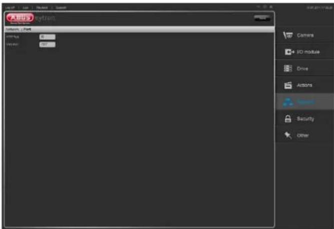
The standard setting for the HTTP port is port 80. The standard setting for the VMS port is port 1927.
Only change these settings if it is necessary.
Security
Security
Click on "Security" to go to the security overview.
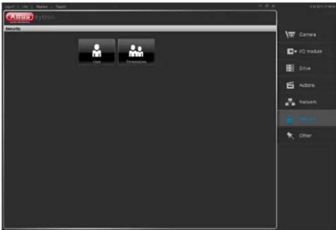
In the security settings, new users can be created, or the system access for each user can be configured individually.
Permissions
Permissions are very important for the software. They allow access to databases and cameras.
When a user logs in, the permission level is always checked.
There are 3 permission levels, which can be set individually:
- Supervisor
- Operator
- Guest
Creating a permission level:

You can define the settings for the permission level as follows:
| No. | Text | Meaning |
| 1 | Permission level | Displays the permission level currently selected |
| 2 | Live image | Set the checkbox for the corresponding camera to grant permission |
| 3 | Playback | Set the checkbox for the corresponding camera to grant permission |
| 4 | Save | Click on “Save” to save your entries |
In the "Live" field you can define the cameras that the user can view and control.
You define access to the database in the "Playback" field. To complete your configuration, please click on "Save". You can now assign the permission level created to a user.
User
You have the option of creating up to 3 users here.

The default user is eytron, which has supervisor permission. For security reasons, this user should be changed, or an individual password assigned.
Also ensure that one user with supervisor permission exists at all times, as only this user can configure the system.
| No. | Text | Meaning |
| 1 | Activate | Tick the “Activate” box |
| 2 | Name | Enter a user name |
| 3 | Password | Enter a user password |
| 4 | Permissions | Select a permission level |
| 5 | Save | Click on “Save” to save your entries |
You have created a new user, which you can now use.
Other
Other
Click on "Other" to go to the overview for other features.

The overview is divided into the following subsections:
- Date/Time
- Firmware update
Click on a symbol to go to the settings.
Date/Time
Here you can enter settings for the date and time.

| No. | Text | Meaning |
| 1 | Current date and time | Shows the setting for the date/time currently stored in the device |
| 2 PC clock | Shows the date/time on the PC from which you access the device | |
| 3 Keep current settings | No changes to the settings | |
| 4 Synchronize with PC | The date and time of the PC are taken over for the device |
| 5 Synchronize with time server (NTP) | Automatic updating of the date and time via a time server (Network Time Protocol)Enter the domain name of the time server(e.g. ptbtime1.ptb.de) |
| 6 Time zone | Select the time zone in which the device is located |
| 7 Summertime/ wintertime | Box ticked: Automatically adjust clockBox not ticked: Do not automatically adjust clock |
| 8 Date and time format | Select a format for the display |
Click on "Save" to accept the changed settings.
Firmware update
Here you can update your firmware.
Under www.abus-sc.com you can download the latest firmware for your product at any time.
Please always ensure that you are using the latest firmware on your 4-channel video storage.

| No. | Text | Meaning |
| 1 | Type | Shows the product name |
| 2 | Version | Version of the installed firmware |
| 3 | Image file | Click on “Search” and select the firmware file |
| 4 | Upload | Click on “Upload” to load the firmware |
It takes a moment to install the new firmware, and the progress display shows this.
After a firmware update, the device restarts and you have to login to the system again.

Note
To be able to perform a firmware update, please connect a drive.

Important
Never disconnect the device from the power supply during a firmware update, as this can damage the device.
Safe mode
If your device will not start correctly, e.g. after a firmware update, then it is in the safe mode.
You can only find your device in the network using the ABUS IP Installer.
Starting screen in safe mode:

In safe mode, please install the latest firmware.
Progress display in safe mode:

Afterwards, your device starts as usual and you can login to the system again.
Troubleshooting
Before calling the Service department, read the following information to determine the possible cause of a malfunction.
| Malfunction Cause Solution | ||
| No power | Mains cable not connected | Connect the mains cable securely to the socket |
| No current in the power socket | Try using a different device at the socket | |
| The connection cable is damaged | Replace the cable | |
| No image | ActiveX is not installed | Install ActiveX (see p. 14) |
| USB port is not working | Device is not supported | Connect a compatible USB medium (USB 2.0) |
| USB hub was used Connect the USB medium directly | ||
| No data on the SD card | Data storage device incorrectly removed | Use the Eject button to remove the data storage device (see p. 26) |
| Network access not possible | Network cable connection is loose | Connect the network cable |
| Network settings are incorrect (DHCP, IP address, etc.) | Check the network configuration and correct it, if necessary (see page 33) | |
| Recording not possible | No drive present | Connect a drive and declare it as a storage drive |
| Sudden deactivation of the device | Temperature inside the device is too high | Clean the device and remove any obstructions from the ventilation area |
Device cleaning and care
Note
- Your device requires no maintenance. Protect the device from dust, dirt and moisture.
Disposal
Information on the EU directive on waste electrical and electronic equipment
To protect the environment, do not dispose of the device with domestic waste at the end of its service life. It can be disposed of at one of the appropriate collection points in your country. Please obey your local regulations when disposing of material.

Dispose of the device in accordance with EU directive 2002/96/EC – WEEE (Waste Electrical and Electronic Equipment). If you have any questions, please contact the department of your local authority which is responsible for waste disposal. Used equipment can be disposed of, for example, by your local or municipal authority, the local waste disposal company or your dealer.
Information on the European RoHS directive
The device complies with the RoHS directive.
Compliance with the RoHS directive means that the product or component does not contain more than the following maximum concentrations of the following substances in homogeneous materials, unless the substance is part of an application that is excluded from the RoHS directive:
a) 0.1% lead (by weight)
b) Mercury
c) Hexavalent chromium
d) Polybrominated biphenyl (PBB) and polybrominated diphenyl ether
e) 0.01% cadmium (by weight)
GPL licence information
Here we wish to inform you that the 4-channel video storage contains Open Source Software, which is licensed exclusively under the GNU General Public Licence (GPL). To ensure that your use of the programs conforms with GPL, please refer to the GPL licence conditions.
Licence text:
The licence text for the GNU General Public Licence can be viewed on the enclosed software CD or on the ABUS Security Center homepage under
http://www.abus-sc.de/DE/Service-
Downloads/Software?q=GPL
Source code
The source codes used can be obtained on request from ABUS Security Center at the e-mail address license@abus-sc.com, to be purchased for up to 3 years.
Technical data
Subject to alterations and errors.
| 4-channel video storage | TVVR35000 |
| IP camera support | ABUS Security - Center |
| Channels (IP only) | 4 x IP @ 2.0 MPx |
| Compression | H.264, MPEG-4, MJPEG |
| Operating mode | Triplex |
| Resolution | 160 x 120 to 1920 x 1080 |
| PTZ control | ABUS pan/tilt IP cameras, video server |
| Total frame rate | 100 fps @ 2.0 MPx |
| Storage medium | 2 x USB 2.0 storage medium, 1 x SD card (max. 32 GB) |
| Network interfaces | RJ-45 Ethernet 10/100 IEEE 802.11 b/g |
| Network access | Web browser, Samba, VMS software |
| Data backup | USB storage medium |
| Alarming | Pre/post alarm buffer 0–60 sec. / unlimited, OSD display, e-mail |
| Operation modes | Manual, schedule, motion detection, video failure |
| Search modes | Date & time |
| User levels | Password manager, 3 authorisation levels, password lists |
| Parallel access | 3 |
| Supported desktop browsers | Internet Explorer 8 32/64 Bit, Firefox 3.6, Chrome 4.1, Safari 5 |
| Desktop browser live view | min. 1024 x 768 |
| Power supply | 100–240 VAC, 50–60 Hz |
| Power consumption | max. 20 W |
| Operating temperature | 5°C ~ 35°C |
| Dimensions (W x H x D) | 95 x 65 x 48.5 mm |
| Weight | 0.2 kg |
| Scope of delivery | 1.8 m power cable, 1.5 m network cable, EU Plug, UK Plug, Manual (on CD), Quickstart manual |
ABUS 4-channel video storage
TVVR35000
Manufacturer:
86444 Affing (Germany)
- ABUS 4-channel video storage TVVR35000
- English
- Device overview
- Status LED
- Overview
- Device overview ....3
- Quick guide....7
- Important safety information....8
- Introduction 11
- System operation....12
- Setting up a connection....13
- Live image....15
- Playback....20
- Configuration....23
- I/O module....25
- Drive 26
- Actions....27
- Network....32
- Security 36
- Other....38
- Troubleshooting....40
- Device cleaning and care 41
- Disposal 41
- GPL licence information....41
- Technical data....42
- Quick guide
- Before you start
- Note
- Establishing the connections
- Configuring the device
- Important safety information
- Explanation of symbols
- Symbol
- Signal word Meaning
- Meaning
- Proper use
- i
- General information
- Warning
- Power supply
- Overloading / overvoltage
- Cables
- Installation location/operating environment
- Ensure the following:
- Care and maintenance
- Accessories
- Putting into operation
- Children and the device
- Introduction
- Disclaimer
- Unpacking the device
- Scope of delivery
- System operation
- Connections
- Starting the device
- Important
- Setting up a connection
- Setting up the system
- Login
- Installing the plug-in
- MS Internet Explorer 8:
- Firefox 3.6, Chrome 4.1 and Safari 5:
- Live image
- Status symbols
- Camera view
- Favourites view
- Operating mode
- Manual recording (Panic Record)
- Camera control
- Using the numeric field
- Camera selection
- Saving camera positions (presets)
- Relays
- Switching the image geometry
- Activating and deactivating the cameras
- Favourites
- Playback
- Presentation view
- Time stream
- Playback bar
- Export
- Configuration
- Camera
- Setting up an IP camera
- Deleting an IP camera
- Extended mode
- I/O module
- Settings
- Drive
- Actions
- Recordings
- Creating a schedule
- Deleting a schedule
- Changing a schedule
- Notifications
- Example for setting up a notification:
- Commands
- Level:
- Edge:
- Example for setting up a command:
- Storage
- Ring archive:
- Alarm archive:
- Example for setting up an archive:
- Network
- General
- LAN
- WLAN
- Ports
- Security
- Permissions
- User
- Other
- Date/Time
- Firmware update
- Safe mode
- Troubleshooting
- Device cleaning and care
- Disposal
- Information on the EU directive on waste electrical and electronic equipment
- Information on the European RoHS directive
- GPL licence information
- Technical data
- ABUS 4-channel video storage
Brand : ABUS
Model : TVVR35000
Category : Dictaphone