
DP-30L - Turntable DENON - Free user manual and instructions
Find the device manual for free DP-30L DENON in PDF.
| Product type | Vinyl turntable |
| Brand | DENON |
| Model | DP-30L (DP-30L(S) silver) |
| Drive system | Direct drive by AC motor |
| Speeds | 33 1/3 rpm, 45 rpm |
| Speed adjustment | ±3% by button, stroboscope |
| Wow and flutter | < 0.018% WRMS |
| Signal-to-noise ratio | > 75 dB (DIN-B) |
| Start-up time | < 2 seconds at 33 1/3 rpm |
| Platter | Die-cast aluminum, diameter 300 mm, weight 1.5 kg |
| Tonearm | Static balance, effective length 220 mm, overhang 16 mm |
| Vertical tracking force | 0–2.5 g (graduation 0.1 g) |
| Anti-skating | Yes, adjustable |
| Automatic lift | Yes, servo-controlled (auto-lift) |
| Included cartridge | DL-8A (MM), output 3 mV, diamond stylus 0.65 mil |
| Cartridge weight | Approximately 5.7 g |
| Headshell weight | 8 g |
| Dimensions (W x D x H) | 450 x 403 x 104 mm (cover closed) |
| Weight | Approximately 9.5 kg |
| Power consumption | 15 W |
| Power supply | Mains (nominal voltage per country) |
| Maintenance | Clean with soft cloth, no lubrication required |
| Safety | Do not expose to humidity, do not open the housing |
| Replacement parts | Stylus DSN-42 (for cartridge DL-8A) |
Frequently Asked Questions - DP-30L DENON
User questions about DP-30L DENON
0 question about this device. Answer the ones you know or ask your own.
Ask a new question about this device
Download the instructions for your Turntable in PDF format for free! Find your manual DP-30L - DENON and take your electronic device back in hand. On this page are published all the documents necessary for the use of your device. DP-30L by DENON.
USER MANUAL DP-30L DENON
OPERATING INSTRUCTIONS
SERVO-CONTROLLED DIRECT DRIVE RECORD PLAYER

INSTRUCTIONS D'UTILISATION
DE PLATINE TOURNE-DISQUES
A ENTRAINEMENT DIRECT ET SERVOCOMMANDE

TO PREVENT FIRE OR SHOCK HAZARD, DO NOT EXPOSE THIS APPLIANCE TO RAIN OR MOISTURE.
Caution
- Handle the power supply cord carefully
Do not damage or deform the power supply cord. If it is damaged or deformed, it may cause electric shock or malfunction when used. When removing from wall outlet, be sure to remove by holding the plug attachment and not by pulling the cord.
- Do not open bottom cover
In order to prevent electric shock, do not open the bottom cover. If problems occur, contact your DENON dealer.
- Do not insert anything inside
Do not insert metal objects or spill liquid inside the record player. Electric shock or malfunction may result.
Model DP.
Serial No.
Please, record and retain the Model name and serial number of your set shown on the rating label.
Models DP-30L and DP-30L S are different only in the base color. The DP-30L is painted dark brown while the DP-30L(S) is painted silver. Except for the base color, all the description about the DP-30L applies to the DP-30L(S) as well.
In some countries, either of the above models only is available.
The wires in this mains lead are coloured in accordance with the following code:
Green-and-yellow:
Earth
Blue:
Neutral
Brown:
Live
As the colours of the wires in the mains lead of this apparatus may not correspond with the coloured markings identifying the terminals in your plug proceed as follows.
The wire which is coloured green-and-yellow must be connected to the terminal in the plug which is marked by the letter E or by the safety earth symbol 12 or coloured green or green-and-yellow.
The wire which is coloured blue must be connected to the terminal which is marked with the letter N or coloured black.
The wire which is coloured brown must be connected to the terminal which is marked with the letter L or coloured red.
FOR YOUR SAFETY
(AUSTRALIAN MODEL ONLY)
To ensure safe operation, the three-pin plug supplied must be inserted only into a standard three-pin power point which is effectively earthed through the normal household wiring.
Extension cords used with the equipment must be three-core and be correctly wired to provide connection to earth. Wrongly wired extension cords are a major cause of fatalities.
The fact that the equipment operates satisfactorily does not imply that the power point is earthed and that the installation is completely safe. For your safety, if in any doubt about the effective earthing of the power point, contact a qualified electrician.
TABLE OF CONTENTS
FEATURES 4
PRECAUTIONS FOR USAGE 7
NAMES OF PARTS AND FUNCTIONS 9
HOW TO ASSEMBLE 12
HOW TO CONNECT 13
ADJUSTMENT 14
HOW TO PLAY. 15
MALFUNCTION ? 24
MAIN SPECIFICATIONS 26
INSTRUCTIONS FOR denon DL-8A STEREO CARTRIDGE 28
INSTRUCTIONS FOR SHURE M75B TYPE 2 CARTRIDGE 30
TABLE DES MATIERES
CHARACTERISTIQUES 4
PRECAUTIONS D'UTILISATION 7
DÉSIGNATION DES PIEÇES ET FONCTIONNALITÉS 10
MONTAGE 16
CONNEXION 17
RÉGLAGES 18
LECTURE DU DISQUE 19
UN MAUVAIS FONCTIONNEMENT ? 24
CHARACTERISTIQUES PRINCIPALES 26
INSTRUCTIONS CONCERNANT LA TÉTE DE LECTURE DENON DL-8A 29
INSTRUCTIONS CONCERNANT LA TÉTE DE LECTURE SHURE M75B TYPE 2 30
INHALTSVERZEICHNIS
1. Auto-lift mechanism with non-contact record-end sensor
The automatic arm lift (auto-lift) mechanism functions in such a way that when a record playback is finished, the tonearm is automatically lifted and the turntable rotation stops. This eliminates worry about unexpected wear of the stylus by leaving record at play. At the end of play, a non-contact record-end sensor senses the velocity change of the tonearm with an opto-electronic transducer, eliminating unnecessary load on the record or stylus, consequently sound quality is not impaired.
2. Newly developed angular control motor for arm lift
The arm lifting device employs a servo controlled angular control motor newly developed by DENON, resulting in a smooth and silent up-and-down tonearm motion.
3. New material employed for base
Newly developed special compound, having larger specific mass and superior vibration damping characteristic than convention al aluminum diecasting is employed for the base. Direct sound pressure from speakers or vibration from floor are isolated and, thus acoustic feed-back is effectively eliminated.
4. Front panel operation provides more flexible operation
The operation buttons and controls are arranged outside the dust over. More over, the speed change-over, start/stop and up/down functions are electrically actuated allowing soft touch button controls.
5. Direct drive system featuring speed detection with magnetic recording and AC motor.
The turntable speed is detected by DENON's magnetic recording detection system having numerous features. An AC motor is employed which has less irregularity of torque and much smoother roatation than a DC motor. Superb wow / flutter and rumble characteristics and stable rotation under various load or external conditions have been accomplished. This is the excellent direct drive system DENON proudly presents.
CHARACTERISTIQUES
In order to use this record player in its optimum condition to perform its best, please read this instruction manual thoroughly and acquire full understanding of correct usage beforehand. For future reference in case of problems, be sure to retain this manual after you read.
ALTERNATION OF THE RATED VOLTAGE AND FREQUENCY
The rated voltage and frequency for your set correspond to the main's voltage and frequency used in the country to which it is shipped. (The rated voltage and frequency are shown on the rating label on the set.) If it is necessary to alter the rated voltage and /or the rated frequency, CONTACT YOUR DENON DEALER.
LISEZ CE MANUEL AVANT L'EMPLOI
1. Handle the detecting head and magnetic coating with care
The speed detection head is positioned with a very small gap to the magnetic coating surface. Do not for any reason loosen the attaching screws. Also be very careful not to scratch the magnetic coating surface when attaching or detaching the turntable platter to or from the motor shaft. Do not bring a magnet near the magnetic coating nor wipe it with solvent such as paint thinner, trichlene, toluene, or the pulse signal for speed detection will be disturbed and accurate speed cannot be expected.
2. When moving tonearm
To provide high performance, the tonearm of this record player consists of many prism parts. Avoid impacts or twisting. Especially in mounting or removing the head-shell, do not forcibly move the tonearm more than the swing range in up-and-down or rotational directions.
3. Take care of the turntable platter
Do not turn the power ON while the turntable platter is removed, nor forcibly stall the platter. Problems may result.
4. Select a suitable location
As much as possible, avoid locations where the turntable is exposed directly to the sun, or where it is moist or dusty. Place it on a horizontal position with little vibration. Ris also recommended to place the speakers and the record player away from each other.
5. No lubrication needed
The motor bearings of this record player are filled with special oil, requiring no further lubrication.
6. In your absence
When the set is to be left unused for a long time, be sure to remove the power supply cord from the wall outlet.
7. Avoid insecticides and chemically treated cloth
Avoid insecticides, benzine or paint thinner since they can discolor or deform the cabinet or dust cover. When removing dust, wipe with soft cloth (such as Silicone cloth). Avoid using a chemically treated cloth since it can discolor or remove the paint.
8. If dust is accumulated on the turntable mat, wash it away with water
PRECAUTIONS D'UTILISATION
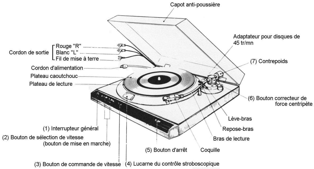
Turns the power ON ( ) and OFF ( ).
(2) Speed selection button (Start button at the same time)
When this button is pressed, the speed is selected, the platter starts protation and at the same time the arm lifter lowers. Press buttons.
"33" for record at 33-1/3 rpm
"45" for record at 45 rpm.
(3) Speed control knob
Turn this knob left or right to vary speed.
(4) Strobe viewing window
Minitor flow of strobe pattern while adjusting the speed.
(5) Stop button
Press this button, and the arm lifter ascends and the motor stops. Because of inertia, the platter continues rotation for a while before it stops.
(6) Anti-skating knob
In playback of record, an attraction force toward inside of record is introduced at the stylus. This force is varied by adjustment of this knob. Refer to page (14) for adjustment.
(7) Counterweight
The stylus force applied to the cartridge is adjusted by this weight. Refer to page (14) for adjustment.
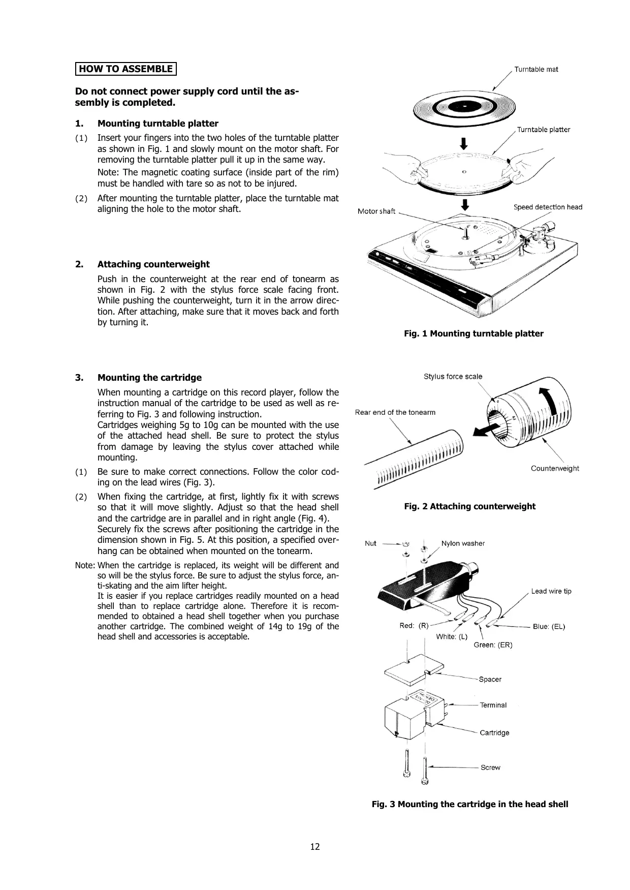
Do not connect power supply cord until the assembly is completed.
1. Mounting turntable platter
(1) Insert your fingers into the two holes of the turntable platter as shown in Fig. 1 and slowly mount on the motor shaft. For removing the turntable platter pull it up in the same way.
Note: The magnetic coating surface (inside part of the rim) must be handled with tare so as not to be injured.
(2) After mounting the turntable platter, place the turntable mat aligning the hole to the motor shaft.
2. Attaching counterweight
Push in the counterweight at the rear end of tonearm as shown in Fig. 2 with the stylus force scale facing front. While pushing the counterweight, turn it in the arrow direction. After attaching, make sure that it moves back and forth by turning it.
3. Mounting the cartridge
When mounting a cartridge on this record player, follow the instruction manual of the cartridge to be used as well as referring to Fig. 3 and following instruction.
Cartridges weighing 5g to 10g can be mounted with the use of the attached head shell. Be sure to protect the stylus from damage by leaving the stylus cover attached while mounting.
(1) Be sure to make correct connections. Follow the color coding on the lead wires (Fig. 3).
(2) When fixing the cartridge, at first, lightly fix it with screws so that it will move slightly. Adjust so that the head shell and the cartridge are in parallel and in right angle (Fig. 4).
Securely fix the screws after positioning the cartridge in the dimension shown in Fig. 5. At this position, a specified overhang can be obtained when mounted on the tonearm.
Note: When the cartridge is replaced, its weight will be different and so will be the stylus force. Be sure to adjust the stylus force, anti-skating and the aim lifter height.
It is easier if you replace cartridges readily mounted on a head shell than to replace cartridge alone. Therefore it is recommended to obtain a head shell together when you purchase another cartridge. The combined weight of 14g to 19g of the head shell and accessories is acceptable.
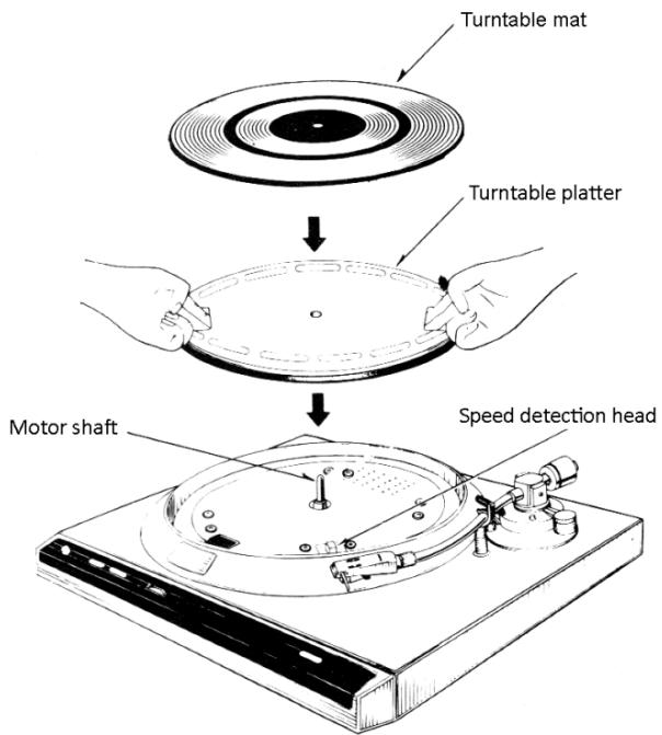
Fig. 1 Mounting turntable platter
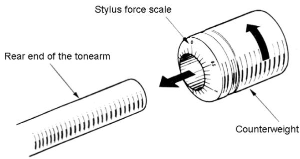
Fig. 2 Attaching counterweight
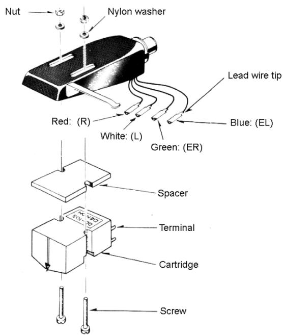
Fig. 3 Mounting the cartridge in the head shell
4. Attaching and detaching head shell on/from tonearm
(1) As shown in Fig. 6, align the guide pin with the slot at the tonearm end and insert.
(2) Turn the lock nut in the arrow direction in Fig. 6 until it stops and fix the head shell to the tonearm.
(3) For removing the head shell, turn the lock nut in the opposite direction of the arrow and gently pull it off.
5. Mounting dust cover
Hold the dust cover near the hinges by both hands as shown in Fig. 7 and push the "metal parts" of the hinges deep enough unto the "hinge catchers" of the cabinet.
For removing the dust cover, open it fully and pull it off in the same mariner.
HOW TO CONNECT
After assembly, make the following connections. Make correct and firm connections. Be sure that the power of amplifier is "off".
(1) Connect the L and R pin plugs of output cord to the L and R "phono" inputs of the amplifier to be used. (Fig. 8)
Also connect the Y-shaped lug of ground wire (combined with the output cord) to the "GND" terminal of the amplifier.
Note: Some cartridges may require a step-up transformer or a head amplifier depending on their type.
(2) Plug in the power supply cord to AC receptacle. (Or else, if AC outlet is provided on your amplifier connect the power supply cord thereto, referring to Fig. 8. Make sure at this time that the power capacity of the outlet is sufficient.)
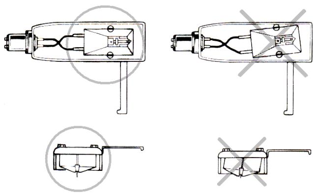
Fig. 4 Cartridge alignment
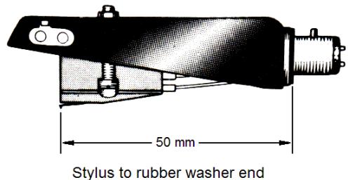
Fig. 5 Stylus point
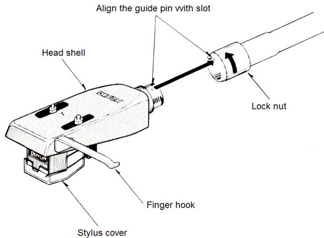
Fig. 6 Attaching head shell
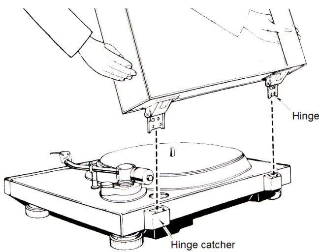
Fig. 7 Mounting dust cover
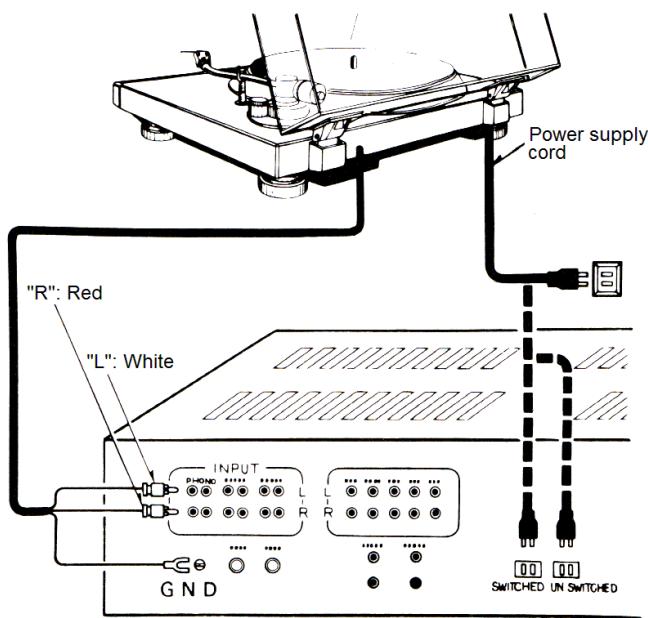
Fig. 8 Connection
ADJUSTMENT
1. Adjustment of stylus force
Set to the optimum stylus force for your cartridge as follows. If it is used with improper stylus force, mistracking or distorted sound may result. Use the cartridge always at optimum stylus force.
(1) Turn the power switch ON ( ).
(2) Press either "33" or "45" speed selection but-ton. Make sure the arm lifter is down and then turn OFF the power switch.
(3) Turn the anti-skating knob and set "0" to the reference line as in Fig. 9.
(4) Remove the stylus cover of the cartridge
(5) See Fig.10 and unlock the arm clamper. Hold the finger hook of the head shell (Fig. 6) with your fingers and remove the tonearm form the arm rest.
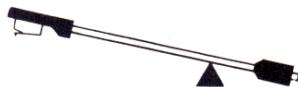
(6) Turn the counter weight to obtain horizontal balance as shown in Fig.11, taking your fingers off momentarily to check.
Note: Carefully and only momentarily remove your fingers to see the balance so that the stylus or tonearm will not be damaged.
(7) After the horizontal balance is obtained, return the tonearm to the arm rest and clamp it by the arm clampsper. Put the stylus cover as well.
(8) Then, being careful not to turn the counterweight, turn only the stylus force scale to bring "0" reading to the reference line. (This condition gives zero stylus force since the horizontal balance of the tonearm has been obtained.)
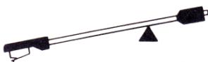
(9) Lastly, turn the counterweight in the arrow direction and bring the desired stylus force "2 (grams)", for example, on the scale ring to the reference line on the tonearm. (When the counterweight is turned, so is the stylus force scale ring. The number shows the stylus force in grams when turned in the arrow direction alter "0" balance. One division corresponds to 0.1 g.) Use whatever stylus force setting is recommended for your cartridge.
2. Adjustment of anti-skating
Turn the anti-skating knob and set the reading of scale to almost the same number as the stylus force. Read the scale at the reference line. Set to "2" on the reference line in the case of stylus force of 2 grams. (Fig. 12)
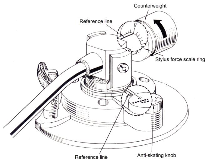
Fig. 9 "0" Setting
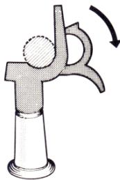
Fig. 10 Arm clamper
Turn the counterweight in the arrow direction in Fig. 9
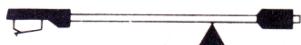
Horizontally balanced
Tum the counterweight in the opposite direction of the arrow in Fig. 9
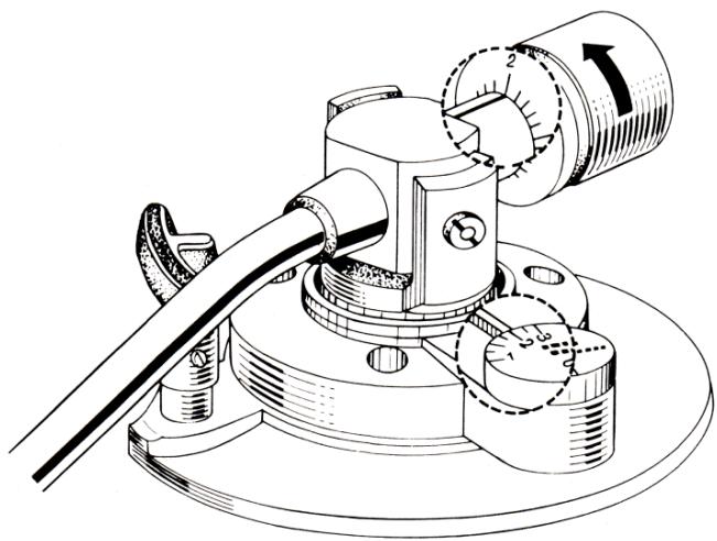
Fig. 11 Obtaining horizontal balance
Fig. 12 Stylus force at 2g
3. Adjustment of arm lifter
Adjust the height of arm lifter as follows. (Fig. 13)
(1) Turn the power switch ON (■) and press either of "33" or "45" speed selection buttons. Making sure the arm lifter is lowered, turn OFF (■) the power switch.
(2) Loosen the height fixing screw and let the arm lifter to the most lowerd position.
(3) Remove stylus cover, release clampper and place the tonearm over the record.
(4) With this condition, adjust the height of the arm lifter so that the gap between the arm lifter and the tonearm pipe is around 0.5 ~mm , and tighten the loosened screw.
Note: In order to avoid damaging the stylus, always put the stylus cover in place except when checking the gap by placing the stylus on the record.
HOW TO PLAY
Starting of play
(1) Turn the power switch ON ( ). The neon lamp in the strobe viewing window lights.
(2) Place a record on the platter, remove the stylus cover on the cartridge and release the arm clamper.
(3) Bring the tonearm over the desired position of the record and press either "33" or "45" speed selection button proper to the record. The indication lamp of the selected speed lights and at the same time, the turntable starts rotation and the stylus is lowered onto the record to start playing.
(4) When the last cut of one side is over, the stylus is automatically lifted off the record (auto-lift), and turntable rotation stops.
- Stopping play in the-middle
Press the stop button. The stylus is automatically lifted off the record and the turntable rotation stops.
- Adjustment of speed
Speed can be adjusted at both "33" and "45" by a single speed control knob. After lowering the stylus on the record, adjust the speed control knob so that the flow of strobe pattern in the strobe viweing window stops. The strobe patterns are lined up as in Fig. 14.
If the strobe pattern is flowing to the left (speed is fast), turn the speed control knob from left to right (to slow down speed), and if it is flowing to the right, turn it from right to left. This control knob changes speed more than ± 3% (Fig. 15)
Note: Even the strobe pattern stands still, it may flow a little, after a while. Since the neon lamp of this record player is lit by commercial power source, the strobe pattern flows if the power source frequency fluctuates even while the turntable speed is constant.
Note: The strobe pattern may sway a little front-and backward. This is because of eccentricity of strobe pattern and not the turntable platter. This causes no wow and flutter.
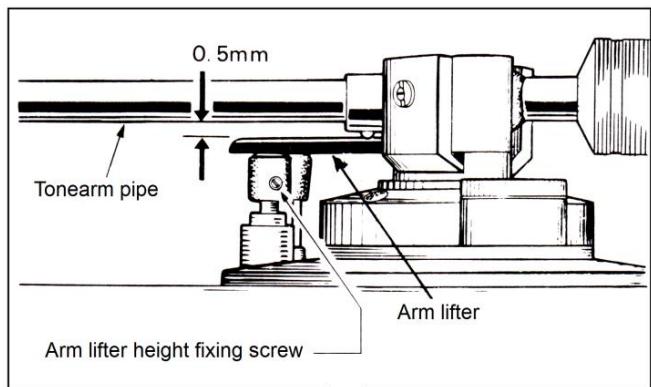
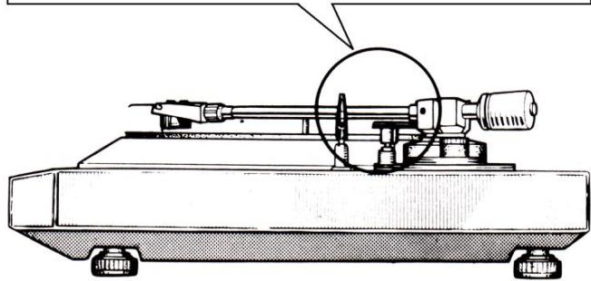
Fig. 13 Arm lifter height adjustment
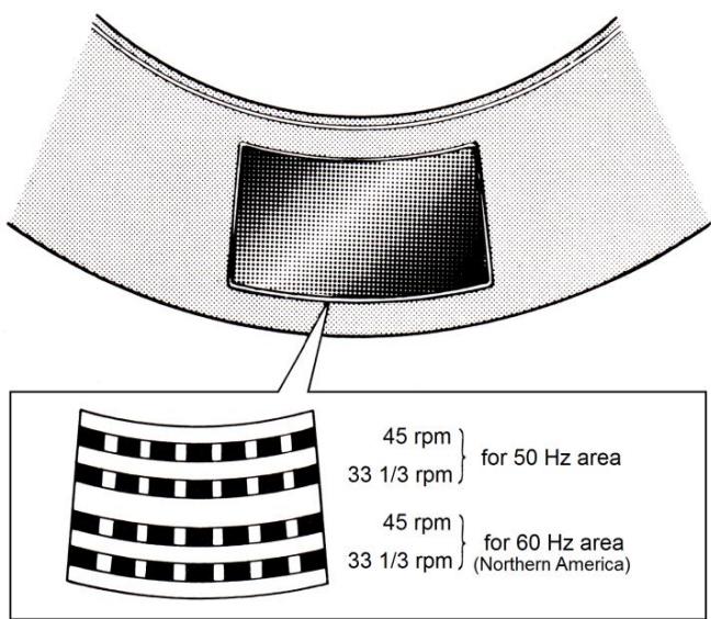
Fig. 14 Line-up of strobe pattern


Fig. 15 Adjustment of strobe pattern
MONTAGE
Malfunction? Please, check the following items
No sound reproduced
Referenceer
- Is cartridge to head shell connection correct? P.12, Fig. 3
- Is output cord connection to amplifier correct? P.13, Fig. 8
- Is adjustment and selection on amplifier correct? Instruction for amplifier.
Hum noise
- Is ground wire connected to amplifier? P.13, Fig. 8
- Is head shell secured by lock nut? P.13, Item 4
- Are pin plugs of output cord securely connected? - P.13, Fig. 8
Mistracking
- Is optimum stylus force set? P.14, Item 1
- Is arm lifter touching tonearm? P.15, Item 3
- Is record warped or scratched? Replace it.
- Is there dust accumulated on stylus? .... Clean it.
Arm does not go forward
- Is arm lifter height properly adjusted? P.15, Item 3
- Is the record scratched? Replace it.
- Is anything touching the tonearm? Check around the arm.
Stylus does not land on the record
- Is stylus force correctly adjusted? P.14, Item 1
- Is there gap between arm lifter and the arm tube? P.15 Item 3
Small sound
- Is amplifier setting suitable for cartridge type (output) ..... P.13, How to connect
Moment of inertia: 190Kg· cm^2 (including turntable mat)
Motor
Speed control system
- Tonearm
Type
Effective length
Overhang
Servo control by frequency detection.
Static balance type with automatic arm lift
220 mm
16 mm
Direct drive by AC motor
33-1/3 rpm, 45 rpm
Over ± 3^
less than 0.018^ , wrms (1)
More than 75dB (DIN-B)
Less than 2,0 sec. to reach 33-1/3 rpm nominal speed.
Diecast aluminum 300mm diam.
Static balance type with automatic arm lift
Tracking error
Stylus force range
Acceptable
cartridge weight
Weight of head shell
Shell connector
Arm lifter
General
Power Supply
Within 3^
0-2.5 g/rot. (1 division is 0.1 g) direct reading
5-10 g (with head shell provided)
8 g (excluding screws, nuts and spacer)
EIA standard 4P connector
Servo controlled by angular control motor
Rated Voltage and frequency are shown on rating label at back of cabinet and/or the label attached to the AC cord
15 W
450W X 403D X 140H (mm) (dust cover closed)
9.5 kg Approx
(1) Measured by DENON's method using magnetic pulse wheel
The above specifications and outward appearance are subject to alteration for improvement
CHARACTERISTIQUES PRINCIPALES
This instruction sheet presents additional instructions about the cartridge attached to the Model DP-30L direct drive record player.
Read this instruction sheet as well as the instruction manual (booklet) for the DP-30L record player.
CAUTION
The DL-8A is an MM (Moving Magnet) cartridge. Therefore, be sure to use amplifier provided with MM phono inputs.
ADJUSTMENT
The optimum stylus force for the DL-8A cartridge is 2g. Adjust the stylus force and antiskating in accordance with the "ADJUSTMENT OF STYLUS FORCE AND ANTI-SKATING" on Page 14 of the booklet.
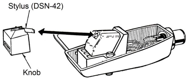
REPLACEMENT OF STYLUS
It depends on conditions of usage, but it is advisable to replace stylus at about every 500 hours of usage.
For replacement, remove the head shell from the tonearm, hold the knob as in the figure bellow and gently pull out the stylus. A new stylus should be fixed in the reverse procedure as above and be inserted firmly to the deepest position. Be sure to specify DENON DSN-42 stylus. If other styli are used, the performance and specifications will not be guaranteed.
REplacement OF CARTRIDGE
If you wish to use other cartridges, refer to "3. Mounting the cartridge" on Page 10 of the booklet. When the cartridge is replaced, the height of arm lifter must be adjusted. Refer also to "3. Adjustment of arm lifter" on Page 16.
SPECIFICATION FOR THE CARTRIDGE
Type:
Type No:
Output voltage:
Channel balance :
Channel separation :
Compliance:
Stylus tip:
Frequency response:
Weight:
Optimum load resistance:
Optimum load capacitance:
Replacement stylus:
MM type stereo cartridge
DL-8A
3mV (1KHz 50mm/s horizontal)
Within 2dB (1KHz)
More than 20dB (1KHz)
8 × 10^-6 ~cm / dyne
16.5 microm (0.65 mil) Radius tip diamond
20-30,000Hz
Approx. 5.7g
Approx. 50K ohms
Approx. 100pF
DSN-42 (0.65 mil, radius tip diamond stylus)
Specifications are subject to alteration for improvement.
5118123007
79.7 Printed in Japan
INSTRUCTIONS POUR LA TÉTE DE LECTURE STÉRÉO DL-8A DU TOURNE-DISQUE DENON DP-30L
*The N75-3 stylus may be used to reproduce the standard 78 rpm records. In this case, the amplifier should be set to "Monaural" or "A+B" mode.
**Formerly M75-6 TYPE 2.
***Formerly N75-6 TYPE 2.
TRACKABILITY:
M75ED TYPE 2 at a stylus force of 1 gram. Stylus force:
400Hz - 22~cm / sec
1,000Hz -33~cm / sec
10,000Hz 19 cm/sec.
M75G TYPE 2 at a stylus force of 1 gram.
400Hz 1 -20~cm / sec
1,000 Hz. — 28 cm/sec
10,000 Hz. — 18 cm/sec
M75B** TYPE 2, and M75EJ TYPE 2 at a stylus force of 2 grams
400 Hz. — 28 cm/sec
1,000 Hz. — 35 cm/sec
10,000 Hz. — 20 cm/sec
(Higher stylus forces within specified range improve trackability.)
FREQUENCY RESPONSE: From 20 to 20,000Hz
CHANNEL SEPARATION : Nominally 25 db at 1,000Hz
INPUT IMPEDANCE: Nominally 47,000 ohms (per channel).
Can be up to 70,000 ohms with almost inaudible change in frequency response.
INPUT CAPACITANCE: 400-500 picofarads per channel, including tonearm wiring and amplifier input capacitance.
INDUCTANCE: 720 millihenries
D.C. RESISTANCE: 630 ohms
MOUNTING: Standard 12 (12.7 mm) mounting center
WEIGHT: 6 grams
TERMINALS:4 terminals
CONNECTIONS: 4-Lead Stereo Connection: Connect "hot" lead of right channel to terminal "R" (usually red) and shield or ground lead of right channel to terminal "RG" (usually green). Connect "hot" lead of left channel to terminal "L" (usually white) and shield or ground lead of left channel to "LG" (usually blue). To prevent "ground loops" and hum, no common connection should be used at cartridge terminals.
CAUTION: Do not make solder connections to cartridge terminals. Make all solder connections to terminal jacks
provided before slipping them over the terminals.
MONAURAL OPERATION: For monaural playback of records, the left and right channels should be connected in parallel. This is accomplished most conveniently by setting the function switch on the associated amplifier to "A+B" or "Mono."
SUGGESTIONS FOR CLEANING YOUR STYLUS : To clean the stylus, use a camel's-hair brush (No. 2 size or smaller) dipped lightly in alcohol or alcohol-water solution; grain alcohol is preferred. (WARNING: Commercial record or stylus cleaning solutions may cause corrosion and permanent stylus damage.) The alcohol will remove any sludge deposits which may have coated the stylus tip. The brush bristles should be trimmed to a length no longer than 14 inch. ALWAYS brush the stylus with a forward movement from the rear (terminal end of the cartridge) to the front. NEVER brush or wipe the stylus from front to back or side to side.
RECORD CLEANING: An effective way to clean a record is to immerse it in a solution of mild dishwashing liquid detergent and lukewarm or cool water (preferably distilled water). Use a lint-free cloth to work the mixture into the grooves, following the grooves around for a thorough cleansing. Then, rinse with clear, cool or lukewarm water (preferably distilled) and dry with a lint-free cloth.
EASY STYLUS REPLACEMENT
Grasp molded housing of stylus between thumb and forefinger. Gently withdraw stylus by pulling forward out of cartridge. Grasp replacement stylus between thumb and forefinger and insert into stylus socket. Press stylus into socket until molded housing of the stylus mates with the cartridge case. Care must be taken not to allow the finger to slip off the molded housing of the stylus, resulting in damage to the stylus tip or shank.
SPECIAL NOTE: The Dynetic stylus assembly used in these cartridges is the most critical component. To maintain the original performance standards of your cartridge, be certain that any replacement stylus you buy bears the following certification on the package: "This Stereo Dynetic stylus is precision manufactured by Shure Brothers Inc."
AVOID INFERIOR IMITATIONS. THEY WILL SERIOUSLY DEGRADE THE PERFORMANCE OF YOUR CARTRIDGE. ALLGenuine "DYNETIC" STYLI ARE MANUFACTURED BY SHURE
BROTHERS INC.
GUARANTEE: This Shure product is guaranteed in normal use to be free from electrical and mechanical defects for a period of one year from the date of purchase. Please retain proof of purchase date. This guarantee includes all parts and labor. This guarantee does not include stylus wear.
SHIPPING INSTRUCTIONS: Carefully repack the unit and return it prepaid to the factory. If outside the United States, return the unit to your dealer or authorized Shure Service Center for repair. The unit will be returned to you prepaid.
PATENT NOTICE: Cartridge and stylus manufactured under one or more of the following U. Patents 3,055,988, 3,077,521, 3,077,522, and 3,463,889.
REEMPLACEMENT DE LA POINTE DE LECTURE

- Caution
- FOR YOUR SAFETY
- (AUSTRALIAN MODEL ONLY)
- TABLE OF CONTENTS
- TABLE DES MATIERES
- INHALTSVERZEICHNIS
- Auto-lift mechanism with non-contact record-end sensor
- Newly developed angular control motor for arm lift
- New material employed for base
- Front panel operation provides more flexible operation
- Direct drive system featuring speed detection with magnetic recording and AC motor.
- CHARACTERISTIQUES
- ALTERNATION OF THE RATED VOLTAGE AND FREQUENCY
- LISEZ CE MANUEL AVANT L'EMPLOI
- Handle the detecting head and magnetic coating with care
- When moving tonearm
- Take care of the turntable platter
- Select a suitable location
- No lubrication needed
- In your absence
- Avoid insecticides and chemically treated cloth
- If dust is accumulated on the turntable mat, wash it away with water
- PRECAUTIONS D'UTILISATION
- Mounting turntable platter
- Attaching counterweight
- Mounting the cartridge
- Attaching and detaching head shell on/from tonearm
- Mounting dust cover
- HOW TO CONNECT
- After assembly, make the following connections. Make correct and firm connections. Be sure that the power of amplifier is "off".
- ADJUSTMENT
- Adjustment of stylus force
- Adjustment of anti-skating
- Adjustment of arm lifter
- HOW TO PLAY
- Starting of play
- - Stopping play in the-middle
- - Adjustment of speed
- MONTAGE
- Malfunction? Please, check the following items
- No sound reproduced
- Hum noise
- Mistracking
- Arm does not go forward
- Stylus does not land on the record
- Small sound
- - Tonearm
- Tracking error
- Stylus force range
- Shell connector
- General
- CHARACTERISTIQUES PRINCIPALES
- REPLACEMENT OF STYLUS
- REplacement OF CARTRIDGE
- SPECIFICATION FOR THE CARTRIDGE
- INSTRUCTIONS POUR LA TÉTE DE LECTURE STÉRÉO DL-8A DU TOURNE-DISQUE DENON DP-30L
- TRACKABILITY:
- EASY STYLUS REPLACEMENT
- REEMPLACEMENT DE LA POINTE DE LECTURE
Brand : DENON
Model : DP-30L
Category : Turntable