
4403 - Router ZOOM - Free user manual and instructions
Find the device manual for free 4403 ZOOM in PDF.


| Product Type | Wireless-N 4-port Router |
| Brand | Zoom |
| Model | 4403 |
| Modes | Router, Ethernet Client, Repeater (WDS) |
| WAN Port | 1 x 10/100 Ethernet (RJ-45) |
| LAN Ports | 4 x 10/100 Ethernet (RJ-45) |
| Wireless Standard | IEEE 802.11b/g/n |
| Frequency Band | 2.4 GHz |
| Antenna | Detachable (1x), external |
| Wireless Security | WEP (64/128-bit), WPA, WPA2 (TKIP/AES) |
| Default SSID | Zoom |
| Default Channel | 10 |
| Default IP Address | 192.168.2.1 |
| Default Admin Password | admin |
| Power Supply | 5V DC, 1.0A |
| DHCP Server | Enabled by default (IP pool 192.168.2.100-200) |
| NAT | Enabled |
| WPS (Wi-Fi Protected Setup) | Supported (push button and PIN methods) |
| WDS (Wireless Distribution System) | Supported (Hybrid and WDS Only modes) |
| Operating Temperature | 0°C to 40°C (32°F to 104°F) |
| Storage Temperature | -20°C to 70°C (-4°F to 158°F) |
| Humidity (non-condensing) | 5% to 90% |
| Dimensions (W x D x H) | Not specified in manual |
| Weight | Not specified in manual |
Frequently Asked Questions - 4403 ZOOM
User questions about 4403 ZOOM
0 question about this device. Answer the ones you know or ask your own.
Ask a new question about this device
Download the instructions for your Router in PDF format for free! Find your manual 4403 - ZOOM and take your electronic device back in hand. On this page are published all the documents necessary for the use of your device. 4403 by ZOOM.
USER MANUAL 4403 ZOOM
This document contains proprietary information protected by copyright, and this Manual and all the accompanying hardware, software, and documentation are copyrighted. No part of this document may be photocopied or reproduced by mechanical, electronic, or other means in any form.
The manufacturer does not warrant that the hardware will work properly in all environments and applications, and makes no warranty or representation, either expressed or implied, with respect to the quality, performance, merchantability, or fitness for a particular purpose of the software or documentation. The manufacturer reserves the right to make changes to the hardware, software, and documentation without obligation to notify any person or organization of the revision or change.
All brand and product names are the trademarks of their respective owners.
© Copyright 2012
All rights reserved.
Contents
Contents 3
Getting Started....5
Package Contents....5
Introduction 5
Using the Router Mode....6
Step 1. Setup Login Password....8
Step 2. WAN Setup 9
Step 3. Wireless Settings....16
Wireless Security Settings....17
Step 4. Summary....19
Step 5. Finish....20
Resetting the Router to the Factory Configuration 21
Ethernet Client Mode 22
Step 1. Setup Login Password....25
Step 2. WAN Type Setup ....25
Step 3. Ethernet Client Mode page 26
Step 4. Summary....27
Step 5. Completing the Installation....29
Setting up the Wireless-N 4-port Router as a Repeater.... 30
Setting up a WDS network 30
Installing the Hardware 31
Setting Up the Router in Hybrid mode or WDS Only mode 32
Setting up a Network 34
To Connect Additional Wired Computers 34
To Connect a Network Device 34
Connecting Wireless Devices to the Wireless-N 4-port Router....36
Establishing your Wireless Network 36
Connecting a Windows 7 Computer with Built-in Wireless Capabilities....37
Connecting a Windows Vista Computer with Built-in Wireless Capabilities ....38
Connecting a Windows XP Computer with Built-in Wireless Capabilities ....39
Connecting a Wireless-enabled Computer or Device (including the iPhone® or other cellular phones, the iPod Touch®, etc.) to the Wireless-N 4-port Router......39
Connecting a Computer with a Wireless Adapter to the Wireless-N 4-port Router...40
Using the Configuration Manager's Advanced Program 42
Changing Default Settings 42
Online Help....42
Launching the Configuration Manager's Advanced Program....43
Configuring Basic Settings 44
The Basic Setup Page 44
The LAN Setup Page....46
The Wireless Settings Page 48
The Change Password Page....51
Configuring Forwarding Rules 52
The Virtual Server Page....53
The Port Triggering Page 54
The Miscellaneous Page 55
Configuring Security Settings 57
Packet Filters Page....57
The Domain Filters Page 59
The URL Blocking Page....60
The MAC Address Control Page 61
The Miscellaneous Page 62
Configuring Advanced Settings....64
The System Time Page 64
The System Log Page....65
The Dynamic DNS Page....67
The QoS Rule Page 68
The SNMP Page 69
The Routing Table Page 70
The Schedule Rule Page 71
Configuring Toolbox Settings....74
System Information Page....74
The Firmware Upgrade/Restore Page 74
The Backup Setting Dialog....75
The Reset to Default Dialog....75
The Reboot Dialog....76
The Miscellaneous Page 76
Appendix A: Troubleshooting Tips 77
Appendix B: TCP/IP Network Settings 80
Macintosh TCP/IP Settings 80
Mac OS X 10.7 (Lion), 10.6 (Snow Leopard), and 10.5 (Leopard)....80
Mac OS X 10.4 and 10.3 80
Mac OS 7.6.1 - 9.2.2....80
Windows TCP/IP Settings 81
Windows 7 Users:....81
Windows Vista Users: 81
Windows XP 82
Windows 2000....82
Windows 98/Mc....82
Appendix C: Setting up Your Network Using WPS 84
Configuration Methods 84
Method One....84
Method Two....84
Method Three 85
Appendix D: Registering Your Product and Getting Help.... 86
Appendix E: Regulatory Information.... 87
Europe - EU Declaration of Conformity 88
Limited Warranty....91
Getting Started
Package Contents
The package contains the Zoom Wireless-N 4-port Router, an RJ-45 Ethernet cable, a 5V 1.0A power cube, a Quick Start flyer, and a CD that contains additional documentation and warranty information.
If anything is missing or damaged, please contact Zoom Customer Support or whoever provided the Wireless-N 4-port Router.
Introduction
The Wireless-N 4-port Router can be used in 3 different modes. Once you determine which mode you want to use, you can follow the relevant chapters of this User Manual.
- Router Mode: The device is set up to be in Router Mode by default. In the Router Mode, the device provides wired and wireless access to clients on a network. Most users will use this mode. To use the Router Mode, go to Chapter 2.
- As an Ethernet Client, the Router allows a device with an Ethernet port, such as a gaming console, computer, or HDTV, to join an existing wireless network. You might use Ethernet Client mode for a device that doesn't have wireless capability, or for a device where you need the superior wireless range of the Wireless-N 4-port Router. To use the Router as an Ethernet Client, go to Chapter 3.
- In the Repeater Mode, the Router is used to extend the range of a wireless network. You can use this mode if, for example, the main wireless Router is in the basement of a multi-floor home and you are unable to access it from some locations. In this instance, you can install the Wireless-N 4-port Router on another floor of the house to provide access to both wired and wireless devices throughout the house. To use the Router as a Repeater, go to Chapter 4.
2
Using the Router Mode
This chapter explains how to setup your Wireless-N 4-port Router in Router Mode. Most users will select this mode. In Router Mode the Wireless-N 4-port Router typically connects to a broadband modem such as a Cable or ADSL modem and becomes the center of a wired and/or wireless network.
Installing the Hardware
1 Place the Wireless-N 4-port Router near a computer to be used for setup. This computer needs an Ethernet (LAN) port.
2 Turn off the computer.
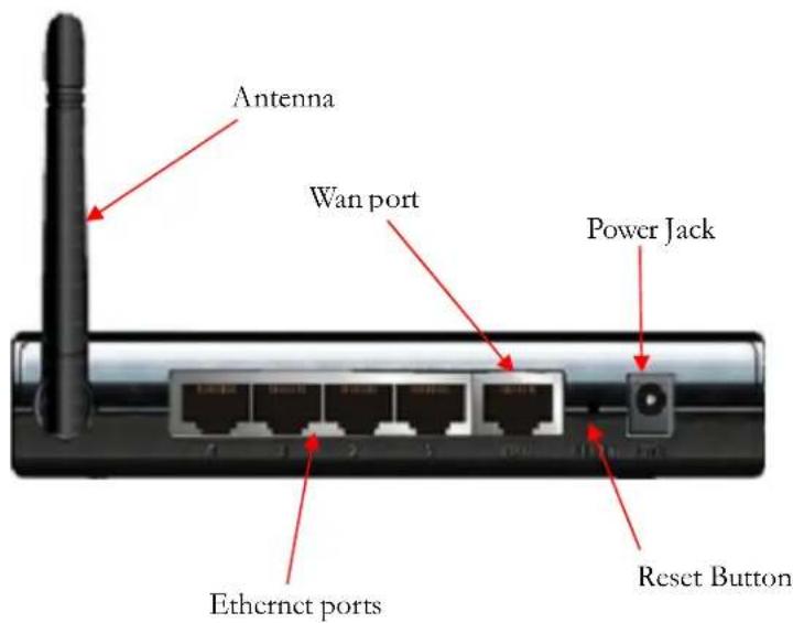
3 Attach the antenna to the Router if the antenna isn't already attached. (Remove the antenna from the package. Place the end of the detachable antenna on the open antenna connection port and rotate the antenna clockwise by hand until it no longer turns easily. It may take many turns before the antenna is completely connected. Move the antenna into a vertical orientation. The antenna should snap into place.)
4 Connect one end of the supplied Ethernet cable to the computer's Ethernet port and the other end to any of the Wireless-N 4-port Router's Ethernet (LAN) ports.
Note: If you are using a Cable or ADSL modem to access the Internet, unplug that Ethernet cable from your computer and plug it into the Router's WAN port. Then connect one end of the supplied
Ethernet cable to the computer's Ethernet port and the other end to any of the Wireless-N 4-port Router's Ethernet (LAN) ports.
5 Plug the supplied power cube into the Wireless-N 4-port Router and then into a power outlet.
Important: Use only the power cube shipped with the Wireless-N 4-port Router. Other power cubes may damage the device.
6 Turn on the computer. The connected Ethernet (LAN) port light should start blinking or stay on. If the connected Ethernet (LAN) light doesn't blink or turn on, please see Appendix A:
Troubleshooting Tips.
Using the Setup Wizard
1 In the computer's Web browser address bar, type http://192.168.2.1 and then click Enter.
2 When the USER'S MAIN MENU opens, it displays a Status page that lists the current values for a variety of settings. If the Status page doesn't appear, please see Appendix A: Troubleshooting Tips.
![System Status [HELP] Item WAN Status Sidenote Remaining Lease Time 00:00:00 Reconfiguring... Internet IP Address 0.0.0.0 Subnet Mask 0.0.0.0 Gateway 0.0.0.0 Domain Name Server 0.0.0.0 Wan MAC Address 00-50-18-64-4A-0D Firmware Version ZOOMv1.0.1 Wireless Status Item WLAN Status Sidenote Wireless mode Enable SSID Zoom Channel 10 Security None MAC Address 00-50-18-64-4A-0E Statistics Information WAN Statistics Inbound Outbound Oclets 0 3762 Unicast Packets 0 0 Non-unicast Packets 0 11 Refresh](/content/2026/05/857512/images/6b250417c82b57780d3f5caa8bc0020d5be993dc8fdc08fd132229f042d81ff0.jpg)
3 In the System Password field, type admin and then click Login.
Note: Later, if you change the System Password, you will use the new password to log in.
4 Click Wizard on the Toolbar to launch the Setup Wizard, which will guide you through the configuration process.

5 The Setup Wizard page opens.
![ZOOM ADMINISTRATOR'S MAIN MENU Status Wizard Advanced Logout Setup Wizard [EXIT] The Setup Wizard will guide you through a basic configuration. ► Step 1. Setup Login Password. ► Step 2. WAN Setup. ► Step 3. Wireless Setup. ► Step 4. Summary. ► Step 5. Finish. < Back [ Start > Password > WAN > Wireless > Summary > finish! ] Next >](/content/2026/05/857512/images/b98490784b8a4303edee1b2025c60bd50b6639faa9654aeee16e33b115e9faea.jpg)
6 Each of the five Steps guides you in configuring a specific setting or group of settings. When you click Next or Back, you move from one step to another. If there is a setting that you don't want to change, simply click Next to go to the next setting.
Step 1. Setup Login Password
To view or change configuration settings, you must enter a password. Your Router's default password admin was set by the factory and you used it to access the Configuration Manager initially. To safeguard your configuration, particularly if you make changes, we recommend that you change the login password. If you want to keep the default password, click Next and continue reading at step 2 below. If you want a new password, continue with step 1 directly below.
1 On the Setup Login Password page, type the old password (initially admin) in the Old Password field.
2 Type the new password in the New Password field.
3 Type the new password in the Reconfirm field, and then click Next.
Note: If you forget the new password, you won't have access to the Configuration Manager and will need to restore the device to its factory settings (see Resetting the Router to the Factory Configuration), thus losing any changes you made to your Router's configuration. To avoid this problem, we recommend that you write the new password here and on the bottom of your Wireless-N 4-port Router, and that you also save it elsewhere such as a settings document.
PASSWORD:
Step 2. WAN Setup
The WAN Type refers to the protocol used by your Internet Service Provider in establishing your Internet connection.
![ADMINISTRATOR's MAIN MENU Status Wizard Advanced Logout Setup Wizard - WAN Type Setup [EXIT] Select Auto Detect your Wan Connection if you are using the router with a Cable or ADSL modem. If you are using Static IP or want to access a network using PPTP or L2TP select Setup your Wan Connection Manually. If you want to use the router to allow a device with an Ethernet port to join an existing wireless network select Setup Ethernet Client Mode. Note: If you select Auto Detect and it is not successful it will automatically take you to the Setup your Wan Connection Manually page. ● Auto Detect your Wan Connection (most users) ○ Setup your Wan Connection Manually ○ Setup Ethernet Client Mode < Back [ Start > Password > WAN > Wireless > Summary > Finish! ] Next >](/content/2026/05/857512/images/a4e4fc692c7e7272867400dff2ea66296b3a7684b13774877136768e4424a360.jpg)
Selecting the WAN Type
On the WAN Type Setup page, you can either Auto Detect your WAN connection or Setup your WAN connection manually.
If you are not sure what connection type you are using, we suggest that you run Auto Detect since it only takes a couple of seconds to run and the Setup Wizard will automatically display the manual setup option page if Auto Detect fails. (The Auto Detect option only detects Dynamic IP and PPPoE.) If you Auto Detect your connection and it is successful, the Setup Wizard will display the appropriate page to set up your connection using either the Dynamic IP page (see Configuring the Dynamic IP Address on page 11) or the PPPoE page (See Configuring PPPoE on page 12) If you Auto Detect your connection and it is not successful, the Setup Wizard will display the Manually Selecting your WAN Type page as shown below.
Manually Selecting your WAN Type
If you selected Setup your WAN Connection Manually or the manual setup option page below appears after you run Auto Detect, select your connection from the following options:
![ADMINISTRATOR's MAIN MENU Status Wizard Advanced Logout Setup Wizard - Select WAN Type [ EXIT ] Dynamic IP Address (DHCP) - Select this if you are using a Cable modem or if your DSL modem does not use PPPoE. Most users will select this. PPP over Ethernet (PPPoE) - Select this if you are plugging a DSL modem into the router, and if your DSL service provider uses PPPoE. A DSL service provider will typically tell you whether you are using PPPoE, which requires you to enter an PPPoE-related password into the router. If you are using DSL with 1483 routed, bridged, or PPPoA modes, you are not using PPPoE. Static IP Address - Your ISP has given you a Static IP address. Typically you must request and pay extra for a static IP. Point to Point Tunneling Protocol (PPTP) - PPTP is more common in corporate environments and most users will not use this setting. Layer 2 Tunneling Protocol (L2TP) - L2TP is more common in corporate environments and most users will not use this setting < Back [ Start > Password > WAN > Wireless > Summary > finish! ] Next >](/content/2026/05/857512/images/793f0b48e2c589f0728fa54cc9030065b859d0cca8c9dac008c5d297530d691a.jpg)
- Dynamic IP Address: Select this if you are using a cable modem or if your ADSL modem does not use PPPoE. Most users will select this. (ADSL service providers will typically tell you whether you are using PPPoE, which requires you to enter a PPPoE-related password into the Router. If you are using ADSL with 1483 routed, bridged, or PPPoA modes, you are not using PPPoE.)
- PPPoE: Select this if you are using an ADSL Router with PPPoE.
- Static IP Address: Typically you must request and pay extra for a static IP. In the unlikely event that you have done this, select Static IP Address.
- L2TP: The Layer 2 Tunneling Protocol is more common in corporate environments and most users will not use this setting. In the unlikely event that you are using a VPN to access a network that uses Layer 2 Tunneling Protocol, select this option.
- PPTP: The Point to Point Tunneling Protocol is more common in corporate environments and most users will not use this setting. In the unlikely event that you are using a VPN that uses Point to Point Tunneling Protocol, select this option.
Note: If you read the discussion above and are still unsure which WAN Type to choose, please check with your service provider.
Click Next.
The relevant section immediately below depends on the WAN Type you selected.
Configuring the Dynamic IP Address
The page shown below only appears if you select the Dynamic IP Address button on the Select WAN Type menu or Auto Detect found a connection using Dynamic IP. Otherwise skip this section.
![ZOOM ADMINISTRATOR'S MAINI MENU Status Wizard Advanced Logout Setup Wizard - WAN Settings - Dynamic IP Address [EXIT] Host Name (optional) Enable Mac Cloning 00-50-18-64-49-FF Clone MAC < Back [ Start > Password > WAN > Wireless > Summary > Finish! ] Next >](/content/2026/05/857512/images/742676a72f5fcaadc00523e42741aeba646f33cd6efc304b3059c06e744d5930.jpg)
- Host Name (optional)
This is the name that identifies your Wireless-N 4-port Router. Some service providers require a host name. Your service provider supplies this name, if needed. Most users don't need to enter a host name.
- Enable Mac Cloning
This is the 12-digit Media Access Control (MAC) address of your Router. Cable Modem users should click the Clone MAC button to get the MAC address that was registered with your service provider for your device. Use the computer that was connected to your cable modem when cloning the MAC address.
Click Next to continue.
Go to Step 3. Wireless Settings
Configuring PPPoE
The page shown below only appears if you select the PPPoE button on the Select WAN Type menu or Auto Detect found a connection that uses PPPoE. Otherwise skip this section.
![ZOOM ADMINISTRATOR's MAIN MENU Status Wizard Advanced Logout Setup Wizard - WAN Settings - PPP over Ethernet [EXIT] PPPoE Username PPPoE Password Primary DNS 0.0.0.0 Secondary DNS 0.0.0.0 PPPoE Service Name (optional) Assigned IP Address 0.0.0.0 (optional) Password > WAN > Wireless > Summary > Finish!] Next >](/content/2026/05/857512/images/5b9b0e51b16ef35e3617672e7d23d87052df2cb96a96dbf209430a0cacdd321a.jpg)
- PPPoE Username
This is the PPPoE username supplied by your service provider.
- PPPoE Password
This is PPPoE password supplied by your service provider.
- Primary DNS
This is the Domain Name System (DNS) server's IP address. Your service provider supplies this address, if needed. Most users should not need to enter a DNS value.
- Secondary DNS
This is the IP address of an alternate Domain Name System (DNS) server. Your service provider supplies this address, if needed. Most users should not need to enter a secondary DNS value.
- PPPoE Service Name
This is the name assigned by your service provider to identify your service. The Service Name is optional. Most users will not enter a Service Name.
- Assigned IP Address
This is the optional IP address assigned by your service provider. Most users will not need to enter an Assigned IP Address.
Click Next to continue.
Go to Step 3. Wireless Settings.
Configuring the Static IP Address
The page shown below will only appear in the unlikely event that you select the Static IP Address button on the Select WAN Type menu. Otherwise skip this section.
![Setup Wizard - WAN Settings - Static IP Address Static IP Address 0.0.0.0 Subnet Mask 0.0.0.0 Default Gateway 0.0.0.0 Primary DNS 0.0.0.0 Secondary DNS 0.0.0.0 Password > WAN > Wireless > Summary > Finish! ] Next >](/content/2026/05/857512/images/a1ba3375478476dcd8ae110bd6c0334f90789f61a5449e77c5c4041d2441c35d.jpg)
- Static IP Address
This is the IP address that is given to you by your service provider when you sign up for a Static IP address. This address identifies your Wireless-N 4-port Router when seen from the Internet.
- Subnet Mask
This is the Router's subnet mask. Your service provider supplies this address.
- Default Gateway
This is the IP address of the ISP server. Your service provider supplies this address.
- Primary DNS
This is the Domain Name System (DNS) server's IP address. Your service provider supplies this address.
- Secondary DNS
This is the IP address of an alternate Domain Name System (DNS) server. Your service provider supplies this address.
Click Next to continue.
Go to Step 3. Wireless Settings.
Configuring PPTP
The page shown below only appears if you select the PPTP button on the Select WAN Type menu. Otherwise skip this section.
![ZOOM ADMINISTRATOR'S MAIN MENU Status Wizard Advanced Logout Setup Wizard - WAN Settings - PPTP [EXIT] IP Mode Dynamic IP Address My IP Address 0.0.0.0 My Subnet Mask 0.0.0.0 Gateway IP 0.0.0.0 Server IP Address/Name PPTP Username PPTP Password < Back [ Start > Password > WAN > Wireless > Summary > Finish! ] Next >](/content/2026/05/857512/images/256e0193ad2a69242da94a08081bc107c9ceb3779e4ee6746d31c3a301001df5.jpg)
- IP Mode
This is the mode used to generate the IP address. Select an option from the dropdown menu, based on your service provider's requirements.
- My IP Address
This is the private IP address that your service provider assigned to your Router.
• My Subnet Mask
This is the private subnet mask that your service provider assigned to your Router.
- Gateway IP
This is the IP address of the service provider's server. Your service provider supplies this address.
• Server IP Address/Name
This is the name and IP address of the PPTP server. Your service provider supplies this information, if needed.
- PPTP Username
This is the PPTP username that your service provider assigned to you.
- PPTP Password
This is PPTP password that your service provider assigned to you.
Click Next to continue.
Go to Step 3. Wireless Settings.
Configuring L2TP
The page shown below only appears if you select the L2TP button on the Select WAN Type menu. Otherwise skip this section.
![ADMINISTRATOR'S MAIN MENU Status Wizard Advanced Logout Setup Wizard - WAN Settings - L2TP [EXIT] IP Mode Dynamic IP Address IP Address 0.0.0.0 Subnet Mask 0.0.0.0 WAN Gateway IP 0.0.0.0 Server IP Address/Name L2TP Username L2TP Password < Back [ $start > Password > WAN > Wireless > Summary > Finish! ] Next >](/content/2026/05/857512/images/28393b095efebe39c317089a8899b4ece91211bcd5aef6d6d3b0f6e8652aab5c.jpg)
- IP Mode
This is the mode used to generate the IP address. Select an option from the dropdown menu, based on your service provider's requirements.
- IP Address
This is the IP address that identifies the L2TP server. Your service provider supplies this address.
- Subnet Mask
This is the Router's subnet mask. Your service provider supplies this address.
- WAN Gateway IP
This is the WAN Gateway IP address of the L2TP server. Your service provider supplies this address.
• Server IP Address/Name
This is the name and IP address of the L2TP server. Your service provider supplies this information, if needed.
• L2TP Username
This is the L2TP username or user name supplied by your service provider.
• L2TP Password
This is L2TP password supplied by your service provider.
Click Next to continue.
Go to Step 3. Wireless Settings.
Step 3. Wireless Settings
The Wireless Settings page lets you change the wireless settings for your Wireless-N 4-port Router. After running the Setup Wizard you will need to make sure that wireless devices connecting to the Wireless-N 4-port Router (computers, phones, tablets, game stations, etc.) are set up properly, compatible with your Router's wireless settings. For instructions, refer to Chapter 6, Connecting Wireless Devices to the Wireless-N 4-port Router.
If you are happy with your wireless settings (set at the factory to wireless without security), click Next. Otherwise, continue below.
![ADMINISTRATOR'S MAIN MENU Status Wizard Advanced Logout Setup Wizard - Wireless Settings [EXIT] Wireless Enable Disabled SSID (Wireless Network Name) Zoom Channel 10 < Back [ 'Start > Password > WAN > Wireless > Summary > Finish! ] Next >](/content/2026/05/857512/images/7919456f6e11aabf0664e775cd84ca502104661aa1ecc735619342387f280b58.jpg)
- Wireless Accept the default Enable. Click the Disable radio button only if you do not want wireless clients to access your network.
- SSID (Wireless Network Name) is the name that you want to give your wireless network. By default, the SSID for the Wireless-N 4-port Router is Zoom. You can change the SSID to a name of your choice. The SSID can be up to 32 alphanumeric characters. If you change the name, make sure that all devices on your Wireless-N 4-port Router's wireless network use the new SSID as the access point.
- Channel refers to the wireless network channel assigned to your LAN. By default, the Wireless-N 4-port Router uses channel 10. You would only change this setting if you were concerned about possible interference from another wireless access point using the same channel.
Note: Other wireless networks might be within range of your network. Your neighbors, for instance, may be within range. If you are having trouble connecting, try setting a different channel to see if that improves performance. You should try setting a channel that is at least a 5 channel difference than what you are using. By default, the Wireless-N 4-port Router is set to 10. You may want to try channel 4 or 5, for instance, if you have trouble connecting with the default channel (10).
Click Next to continue.
Wireless Security Settings
If you accepted the default to Enable the Wireless Module (on the Wireless Settings page at Step 3), the following page opens when you click Next.
![ADMINISTRATOR'S MAIN MENU Status Wizard Advanced Logout Setup Wizard - Wireless Security [EXIT] Security None None WEP WPA / WPA2 < Back [ Start > Password > WAN > Wireless > Summary > Finish! ] Next >](/content/2026/05/857512/images/0edf52c73c60ad50951c04a55092e75935de964893384c08499b7adbae6c9a83.jpg)
From the drop-down menu, you can choose either none, WEP, or WPA2/WPA. By default, the Router does not have security enabled. However, we strongly recommend that you configure wireless security for your network. You need to use the same security mode you select for your wireless Router for each wireless device using the Router. If a Pass Phrase or WEP key is used, it needs to be the same for all devices including the Router.
Select from the following options:
WPA2/WPA (Recommended): Most users should select the WPA2/WPA option. When you select this option, the Security Key field appears.
- Security Key: Please input 8 to 63 characters as your Security key.
| Field Entry | |
| Security Key | In the Security Key field, enter a value for the key between 8 and 63 characters.Write your key in the space below for future reference, and then enter it in the Security Key field:———————————————————————————— |
- WEP: You must select this option in the unlikely event that you have devices on your network that only support WEP. Otherwise we recommend WPA2/WPA. (Devices that only support WEP include older handheld game consoles, older MAC notebooks, and very old Windows notebooks. If you need to use WEP, enter the correct encryption key.)
| Field Entry | |
| Encryption WEP Key 1, 2, 3, 4 | You can choose to either use WEP 128 bit encryption or WEP 64 bit encryption. The difference is 128 bit is more secure and 64 bit is faster. We recommend selecting 64 bit.If you chose a 64-bit key length, 10 Hexadecimal characters are required. Hexadecimal characters are the numbers 0-9 and the characters A-F. Write the 10 Hexadecimal character key in the space below for future reference, and then enter it in the Key 1 box.____If you chose a 128-bit key length, 26 Hexadecimal characters are required. Hexadecimal characters are the numbers 0-9 and the characters A-F. Write the 26 Hexadecimal character key in the space below for future reference, and then enter it in the Key 1 box.____ |
None (the default): Select this if you don't plan to use wireless security or if all the devices on your network support WPS (WiFi® Protected Setup) and you wish to use WPS to set up wireless security. We recommend using the Setup Wizard with the options above to set up security for your Wireless-N 4-port Router. However, if you choose to use WPS, please refer to Appendix C: Setting up Your Network Using WPS.
Click Next.
Step 4. Summary
The Summary page displays the updated configuration settings for your Router and lets you accept, change, and test the configured values.
1 To edit your entries, click Back as many times as needed to access the page for the field(s) to be edited, then click Next to continue with your edits or to return to the updated Summary page.
2 The Wireless-N 4-port Router is set by default to test your network connection. If you do not wish to test your connection, please uncheck the Do you want to proceed with the network testing? checkbox.
3 When you're satisfied with the configured settings, click Confirm to save the new configuration.
![[WAN Setting] WAN Type Dynamic IP Address Host Name - Enable Mac Cloning 00-50-18-64-49-E5 [Wireless Setting] Wireless On SSID (Wireless Network Name) Zoom Channel 10 Security None ✓ Do you want to proceed with the network testing? < Back [ Start > Password > WAN > Wireless > Summary > Finish! ] Confirm Setup Wizard - Summary [ EXIT ] Please confirm the information below.](/content/2026/05/857512/images/fc6124c50fde63d162a57f5aa45565c4db8540ceae0e1a7b30a4ed750fd0ddc6.jpg)
Step 5. Finish
The Finish page displays the saved configuration settings for your Router.
![ZOOM ADMINISTRATOR's MAIN MENU Status Wizard Advanced Logout Setup Wizard - WAN Connection Test [EXIT] Congratulations!! The Internet connection is established. Connection information is WAN Type Dynamic IP Address IP Address 100.100.1.88 Submit Mask 255.255.255.0 Gateway 100.100.1.1 Domain Name Server 10.0.0.240 < Back [ Start > Password > WAN > Wireless > Summary > Finish! ] Finish](/content/2026/05/857512/images/bbdb53778823b8a2fb44924ea21de6d6078743d4a5680e798c403450c81b0bdf.jpg)
Click Finish to exit the Setup Wizard and return to the Main Menu.
Important! If you see the message "Connection to Internet Failed!" try the following:
- Check that the Ethernet cables are all securely connected.
- Check that you have installed an Ethernet cable from the Router's WAN port to the Ethernet port of your Cable or ADSL modem.
- Power off your computer, the Router and your modem, and then turn on modem and allow it to connect. Next turn on the Router, wait until the Router is completely powered up and the WLAN light is blinking, then turn on your computer. Try running the setup wizard again.
- Click the Reconfigure button and go through the configuration again. This time uncheck the Do you want to proceed with the Network Testing? button. After you Apply the settings, try opening your browser and going to your favorite web page. If this doesn't work contact Zoom Technical Support. See Appendix D, Registering your Product and Getting Help.
Congratulations! Your Wireless-N 4-port Router is now setup. If you need help connecting additional computers or devices to your Wireless-N 4-port Router please refer to:
Chapter 5, Setting up a Network for help on adding other computers or network devices through the Wireless-N 4-port Router's Ethernet ports.
Chapter 6, Connecting Wireless Devices to the Wireless-N 4-port Router for help on connecting wireless computers, phones, tablets and game stations.
In the unlikely event you need to make changes to the Wireless-N 4-port Router's advanced settings please see Chapter 7, Using the Configuration Manager's Advanced Program.
In the unlikely event that you need to reset the Router to the factory default configuration, insert the blunt end of a paper clip into the RESET hole on the back panel of the Router. Hold the clip in place for five (5) seconds.
3
Ethernet Client Mode
This chapter explains how to setup your Wireless-N 4-port Router as an Ethernet Client. Ethernet Client Mode allows a game station, computer, HDTV, or other device with an Ethernet port to use the Router to connect to a wireless network.
Configuring the Router by Using a Computer
1 Place the Wireless-N 4-port Router near a computer to be used for setup. This computer needs an Ethernet (LAN) port. This computer will be used to set up the Wireless-N 4-port Router. After the setup is complete, the Router can be connected to the device that needs wireless capability.
2 Turn off the computer.
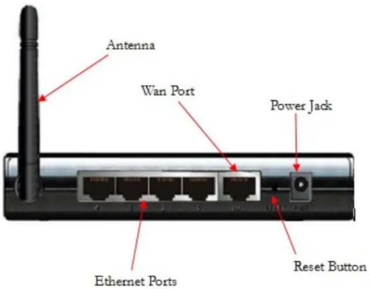
3 Attach the antenna to the Router if the antenna isn't already attached. (Remove the antenna from the package. Place the end of the detachable antenna on the open antenna connection port and rotate the antenna clockwise by hand until it no longer turns easily. It may take many turns before the antenna is completely connected. Move the antenna into a vertical orientation. The antenna should snap into place.)
4 Connect one end of the supplied Ethernet cable to the computer's Ethernet port and the other end to any of the Wireless-N 4-port Router's Ethernet (LAN) ports.
5 Plug the supplied power cube into the Wireless-N 4-port Router, and then into a power outlet.
Important: Use only the power cube shipped with the Wireless-N 4-port Router. Other power cubes may damage the device.
6 Turn on the computer. The connected Ethernet (LAN) port light should start blinking. If the connected Ethernet (LAN) light doesn't blink, please see Appendix A: Troubleshooting Tips.
Using the Setup Wizard
To launch the Configuration Manager, please follow these steps:
1 In the computer's Web browser address bar, type http://192.168.2.1 and then click Enter.
2 When the USER'S MAIN MENU opens, it displays a Status page that lists the current values for a variety of settings. If the Status page doesn't appear, please see Appendix A: Troubleshooting Tips.
![USER'S MAIN MENU Status System Password : 1 (default: admin) Login System Status [HELP] Item WAN Status Sidenote Remaining Lease Time 00.00.00 Reconfiguring... Internet IP Address 0.0.0.0 Subnet Mask 0.0.0.0 Gateway 0.0.0.0 Domain Name Server 0.0.0.0 Wan MAC Address 00-50-18-64-4A-0D Firmware Version ZOOM V1.0.1 Wireless Status Item WLAN Status Sidenote Wireless mode Enable SSID Zoom Channel 10 Security None MAC Address 00-50-18-04-4A-0E Statistics Information WAN Statistics Inbound Outbound Octels 0 3762 Unicast Packets 0 0 Non-unicast Packets 0 11 Refresh](/content/2026/05/857512/images/cfe80022d02f4eeb8e613a771457c50c1b7fdd45dfcec409cbff935252e0b05d.jpg)
3 In the System Password field, type admin and then click Login.
Note: Later, if you change the System Password, you will use the new password to log in.
4 Click Wizard on the Toolbar to launch the Setup Wizard, which will guide you through the configuration process.

5 The Setup Wizard page opens.
![ZOOM ADMINISTRATOR's MAIN MENU Status Wizard Advanced Logout Setup Wizard [EXIT] The Setup Wizard will guide you through a basic configuration. ► Step 1. Setup Login Password. ► Step 2. WAN Setup. ► Step 3. Wireless Setup. ► Step 4. Summary. ► Stop 5. Finish. < Back [ Start > Password > WALL > Wireless > Summary > Finish! ] Next >](/content/2026/05/857512/images/eb2b449ff81b9e79a2212d384f3ab07c4c0d0e54c5f0252ea4174eefc27d3d9e.jpg)
6 Each of the Steps guides you in configuring a specific setting or group of settings. When you click Next or Back, you move from one step to another. If there is a setting that you don't want to change, simply click Next to go to the next setting.
Step 1. Setup Login Password
To view or change configuration settings, you must enter a password. Your Router's default password admin was set by the factory and you used it to access the Configuration Manager initially. To safeguard your configuration, particularly if you make changes, we recommend that you change the login password. If you want to keep the default password, click Next and continue reading at step 2 below. If you want a new password, continue at step 1 directly below.
1 On the Setup Login Password page, type the old password (initially admin) in the Old Password field.
2 Type the new password in the New Password field.
3 Type the new password in the Reconfirm field, then click Next.
Note: If you forget the new password, you won't have access to the Configuration Manager and will need to restore the device to its factory settings (see Resetting the Router to the Factory Configuration), thus losing any changes you made to your Router's configuration. To avoid this problem, we recommend that you write the new password here and on the bottom of your Wireless-N 4-port Router, and that you also save it elsewhere such as a settings document.
PASSWORD:
Step 2. WAN Type Setup
On the WAN Type Setup page, select Setup Ethernet Client Mode. Then click Next.
![ADMINISTRATOR's MAIN MENU Status Wizard Advanced Logout Setup Wizard - WAN Type Setup [EXIT] Select Auto Detect your Wan Connection if you are using the router with a Cable or ADSL modem. If you are using Static IP or want to access a network using PPTP or L2TP select Setup your Wan Connection Manually. If you want to use the router to allow a device with an Ethernet port to join an existing wireless network select Setup Ethernet Client Mode. Note: If you select Auto Detect and it is not successful it will automatically take you to the Setup your Wan Connection Manually page. ○ Auto Detect your Wan Connection (most users) ○ Setup your Wan Connection Manually ● Setup Ethernet Client Mode < Back [ Start > Password > WAN > Wireless > Summary > Finish! ] Next >](/content/2026/05/857512/images/cfbbf8c94089291a8ad7c86a1666812e21e6241457b67d767dd2c7c168f9ffa1.jpg)
Step 3. Ethernet Client Mode page
1 Select the Enabled button to enable Ethernet Client Mode.
2 Select the radio button corresponding to the name of the wireless network (the SSID) you want to join.
3 If the wireless network you selected has security enabled, enter the Security Key used by your wireless network.
4 Click Next.
![Setup Wizard - Ethernet Client Mode [EXIT] Ethernet Client Mode Disable Enable SSID (Wireless Network Name) Security None None WEP WPA WPA2 Channel Signal Strength Security MAC Address Select SSID 1 0 WPA 00-13-10-EB-02-08 piano1 1 24 None 00-26-99-74-3B-C8 Imaginatik 1 50 WPA 00-17-C5-41-99-5F MDAWIFI 1 81 WPA 00-01-38-E1-A7-34 RemoteX6 1 5 WPA2 AC-67-06-73-B3-28 Credo-guest 1 96 None 00-40-36-3D-52-80 Zoom 10 WPA2 00-23-33-2C-D6-52 PS Voice 1 0 WPA2 00-23-33-2C-D6-51 Platform Solutions 1 96 None 00-40-36-3B-D5-CC Zoom 10 None 00-50-18-64-49-B6 Zoom 10 WPA2 00-16-D6-DA-D9-99 LBL 2 WPA2 00-50-18-21-D0-BF 4501 10 WPA2 E0-46-SA-37-A0-4A 4 WPA2 AC-67-06-33-B2-B8 Credo-guest 6 WPA2 AC-67-06-73-B2-B8 x7nfourth 6 WPA2 C8-3A-35-57-4F-19 Zoom 10 None 00-50-18-64-4A-OE zmo2014a 10 WPA 00-40-36-3D-6D-CF Media Silo T1 11 WPA2 00-24-36-AA-ED-51 Undo Scan AP < Back [ Start > Password > WAN > Wireless > Summary > Finish! ] Next >](/content/2026/05/857512/images/20180b8eb0be25fb27bcf120851effabea646ae510c6b0c69d0172b46174b34d.jpg)
Step 4. Summary
Click Confirm.
![ADMINISTRATOR's MAIN MENU Status Wizard Advanced Logout Setup Wizard - Summary [EXIT] Please confirm the information below. [Ethernet Client Mode] Ethernet Client mode Enable SSID Zoom < Back [ Start > Password > Ethernet Client Mode > Summary > Finish! ] Confirm](/content/2026/05/857512/images/c97977d6a60cf30f9382f50f8a1acf7b2593422c58c8a4cd4bcb30dd0217874d.jpg)
Next click Finish to go to the Status page.
![ZOOM ADMINISTRATOR's MAIN MENU Status Wizard Advanced Logout Setup Wizard [EXIT] Configuration is Completed. Please click Finish to complete your setup. This will take you to the Status page. Click Configure Again to run the setup wizard again. Configure Again [ Start > Password > Ethernet Client Mode > Summary > Finish! ] Finish](/content/2026/05/857512/images/d7e2b4e5b577e3ebed9cc0a130b128fb14919690ba94b7d9aa61da8751595a16.jpg)
You should now see the Ethernet Client Mode status. If it displays Connected your setup is complete. Congratulations!
(You may need to click the Refresh button to update the page if it does not say Connected.)
![ADMINISTRATOR's MAIN MENU Status Wizard Advanced Logout Ethernet Client Mode [HELP] Item Ethernet Client Mode Status Sidenote Ethernet Client mode Enable Connected SSID Zoom Channel 1 Security WPA2 (AES) MAC Address 00-50-18-64-49-E5 Edit View Log... Clients List... NAT Status... Refresh](/content/2026/05/857512/images/6bee7e664f5fdf1593c6e6974856e85a6dd9d4087bd0e57adfb237dd1d8da460.jpg)
Step 5. Completing the Installation
If you want to use the same PC (the one that you used to configure the Router) to connect to the Internet, please remove the Ethernet cable from the Ethernet port on the back of the Wireless-N 4-port Router and move it to the WAN port. Close all open browser windows and reboot the computer. When the computer powers up, open a browser and visit a webpage. If you are able to connect to the Internet, Congratulations! If you cannot connect to the Internet, please refer to Appendix A: Troubleshooting Tips.
If you want to give wireless access to a device other than the computer that you used to setup the Router you will need to move the Router to this device. Unplug the Ethernet cable from both the Router's Ethernet port and your computer's Ethernet port. (If you need to physically move the Router, unplug the power cube from the power outlet, move the Router to its new location and plug the power cube back in.) Power off the device that you wish to give wireless access. Now plug one end of the Ethernet cable into your device's Ethernet port. Plug the other end of the Ethernet Client into the Routers WAN port. Power back on your device. When the device powers up, try connecting to the Internet. If you are able to connect to the Internet, Congratulations! If you cannot connect to the Internet, please refer to Appendix A: Troubleshooting Tips.
In the unlikely event that you need to make changes to the settings, remove the Ethernet cable from the WAN port on the Wireless-N 4-port Router and move it to one of the Ethernet ports. Then reconnect the other end of the Ethernet cable to a PC. Power off the computer and power it back on. (This is important because the computer must locate the correct IP address for the modem. This is done when the computer is turned back on.) Log in to the Configuration Manager to use the Setup Wizard following the instructions at the beginning of this section.
Note: If you had to unplug any cables or make any changes to the computer that you used to configure the Wireless-N 4-port Router you now should restore that computer back to its original state.
Setting up the Wireless-N 4-port Router as a Repeater
This chapter explains how to set up the Wireless-N 4-port Router as a Repeater using WDS (Wireless Distribution System) to boost and extend the range of your wireless network. WDS is especially useful in large homes or workplaces, including ones with multiple floors. Additional routers may be used to extend the range of your wireless network in any direction. These routers can either connect to each other or to a central router.
Setting up a WDS network
Setting up a WDS network typically requires you to setup at least two routers. A base station router that is connected to your Cable or ADSL modem (or in the case of a wireless Cable or ADSL modem that supports WDS, the modem itself), and a remote station router that is located closer to the devices that are having trouble accessing your wireless network. The setup for the Wireless-N 4-port Router is the same whether or not you are using it as a base station or a remote station. However if you are using the Wireless-N 4-port Router as the base station you should have already configured the WAN connection as described in Chapter 2.
If you are using a router other than the Wireless-N 4-port Router as your base station you may need to setup WDS on that router. If you are unsure if you need to setup WDS in your router we recommend first setting up the Wireless-N 4-port Router as your remote station and trying to connect to the base station. If you are able to connect and access the Internet, you do not need to perform any additional setup on your router. If you can not access the Internet you may need to setup up the other router. Please refer to the documentation included with your device.
Note: You may need to know the Wireless-N 4-port Router's Wireless MAC address to setup the other router. The Wireless MAC address is located on the Wireless-N 4-port Router's Status page. Select the Wireless MAC address that appears in the middle of the page in the Wireless Status section, not the WAN MAC address in the System Status section.
If you wish to extend the range of your wireless network even further you may add additional Wireless-N 4-port Routers to your network. These routers can connect either to your base station router or to an existing remote station router.
Deciding which WDS Mode to Use
The Wireless-N 4-port Router supports both Hybrid Repeater mode and WDS Only mode. Hybrid mode is used when you want to extend the range of your wireless network to both wired
and wireless devices. WDS Only mode (also called a wireless bridge) only allows wired devices to be connected directly to the Repeater. WDS Only mode is typically used when you wish to connect two separate wired networks. Most users should select Hybrid mode.
Installing the Hardware
1 Place the Wireless-N 4-port Router near a computer to be used for setup. This computer needs an Ethernet (LAN) port.
2 Turn off the computer.
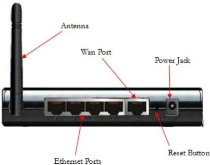
3 Attach the antenna to the Router if the antenna isn't already attached. (Remove the antenna from the package. Place the end of the detachable antenna on the open antenna connection port and rotate the antenna clockwise by hand until it no longer turns easily. It may take many turns before the antenna is completely connected. Move the antenna into a vertical orientation. The antenna should snap into place.)
4 Connect one end of the supplied Ethernet cable to the computer's Ethernet port and the other end to any of the Wireless-N 4-port Router's Ethernet (LAN) ports.
5 Plug the supplied power cube into the Wireless-N 4-port Router, and then into a power outlet. Important: Use only the power cube shipped with the Wireless-N 4-port Router. Other power cubes may damage the device.
6 Turn on the computer. The connected Ethernet (LAN) port light should start blinking. If the connected Ethernet (LAN) light doesn't blink, please see Appendix A: Troubleshooting Tips.
Setting Up the Router in Hybrid mode or WDS Only mode
To launch the Configuration Manager, please follow these steps:
1 In the computer's Web browser address bar, type http://192.168.2.1 and then click Enter.
2 When the USER'S MAIN MENU opens, it displays a Status page that lists the current values for a variety of settings. If the Status page doesn't appear, please see Appendix A: Troubleshooting Tips.
![USER'S MAIN MENU Status System Password : [default: admin] Login System Status [HELP] Item WAN Status Sidenote Remaining Lease Time 00.00.00 Reconfiguring... Internet IP Address 0.0.0.0 Subnet Mask 0.0.0.0 Gateway 0.0.0.0 Domain Name Server 0.0.0.0 Wan MAC Address 00-50-18-64-4A-0D Firmware Version ZOOM v1.0.1 Wireless Status Item WLAN Status Sidenote Wireless mode Enable SSID Zoom Channel 10 Security None MAC Address 00-50-18-04-4A-0E Statistics Information WAN Statistics Inbound Outbound Octels 0 3762 Unicast Packets 0 0 Non-unicast Packets 0 11 Refresh](/content/2026/05/857512/images/a03d0e37d7356241a2b694f37bfaf76a3cb037d3fa7a77ef8c3053b6d0a45db4.jpg)
3 In the System Password field, type admin and then click Login.
Note: Later, if you change the System Password, you will use the new password to log in.
4 Click on Advanced Setup. Click Enter.
5 Click Wireless from the left-side menu.
6 At WDS, click Configure.
7 On the WDS Settings page, select either WDS Only or Hybrid from the AP Mode drop-down menu.
Note: Hybrid mode allows wired and wireless access to the Wireless-N 4-port Router; WDS Only does not allow wireless access to the Wireless-N 4-port Router. Most users should select Hybrid mode.
8 From the Scanned AP's MAC drop-down menu, select the SSID (Wireless Network Name) of the AP (your Router is in Access Point mode when it broadcasts wirelessly) you want to connect to. The Scanned AP's MAC drop-down menu displays both the MAC address and SSID of the Wireless Networks that it has found. Make a note of what wireless channel and the type of security the AP you are connecting to is using.
9 From the Remote AP MAC drop-down menu, select the number of the field you want the MAC Address to be copied to, then click Copy to. Most users should select 1 to copy it to the first field.
10 Click Save to save your WDS settings.
11 Next, set up the Wireless-N 4-port Router to use the same wireless channel and security as the AP you just connected to. Click Wireless from the left-side menu to go to the main wireless page.
12 Select the Channel that the AP you just connected to is using from the drop-down menu.
13 Then select the Security type and enter the corresponding Key. Then click Save.
14 If this Wireless-N 4-port Router is not connected directly to your Cable or ADSL modem you should disable DHCP on the Wireless-N 4-port Router.. Disabling DHCP means that only the router connected to your modem will assign IP addresses.
To disable DHCP on the Wireless-N 4-port Router:
- Click LAN Setup from the menu.
- At the DHCP Server, select Disable. Then click Save.
- Click Reboot. At the message prompt, click OK.
- Close the browser. (You do not need to wait for it to reboot.) Then reboot the PC.
Note: If you had to unplug any cables or make any changes to the computer that you used to configure the Wireless-N 4-port Router you now should restore that computer back to its original state.
Congratulations! Your Wireless-N 4-port Router is now setup in Repeater mode. If you need help connecting additional computers or devices to your Wireless-N 4-port Router please refer to:
Chapter 5, Setting up a Network for help on adding other computers or network devices through the Wireless-N 4-port Router's Ethernet ports.
Chapter 6, Connecting Wireless Devices to the Wireless-N 4-port Router for help on connecting wireless computers, phones, tablets and game stations.
In the unlikely event you need to make changes to the Wireless-N 4-port Router's advanced settings please see Chapter 7, Using the Configuration Manager's Advanced Program.
Setting up a Network
Once the Wireless-N 4-port Router is set up in either Router Mode or Repeater Mode, you may now go ahead and set up the rest of your network. (If you are using the Wireless-N 4-port Router in Ethernet Client mode, skip this chapter.)
To set up your network, you can do any or all of the following, in any order that you choose:
- If you want to connect additional computers directly to the Wireless-N 4-port Router, see To Connect Additional Wired Computers below.
- If you want to connect additional computers or other devices using a wireless network, you should go to Chapter 6, Connecting Wireless Devices to the Wireless-N 4-port Router.
- In the unlikely event that you want to connect a hub, switch, router or other device directly to the Wireless-N 4-port Router, see To Connect a Network Device on page 34.
To Connect Additional Wired Computers
You can connect up to four computers that have Ethernet ports directly to the Wireless-N 4-port Router.
1 Shut down and power off the computer you want to connect to the Wireless-N 4-port Router. (This is important because the computer must locate the correct IP address for the modem. This is done when the computer is turned back on in step 3 below.)
2 Plug one end of an Ethernet cable into one of the Wireless-N 4-port Router ETHERNET ports and plug the other end into the computer's Ethernet port.
3 Turn on the computer.
4 Verify that your Internet connection is working. Open your Web browser (for instance, Internet Explorer, Firefox, or Chrome) and try to connect to a familiar Web address. If you are able to connect to the Internet, Congratulations! If you cannot connect to the Internet, please refer to Appendix A: Troubleshooting Tips.
5 Repeat steps 1–4 for each computer you want to add.
To Connect a Network Device
You can use one of the 4 ETHERNET (LAN) ports on the the Wireless-N 4-port Router to plug in a network device (for example, a hub, switch, router, or Homeplug adapter).
1 Plug one end of an Ethernet cable into one of the Wireless-N 4-port Router ETHERNET ports and the other end into the network device's Ethernet port. (For a hub or a switch, this is typically called an Uplink or Expansion port. For a router, this is typically called a WAN port.)
2 Set up your network and/or device. Refer to the documentation provided with your particular network device for instructions on how to do this.
3 Once your network and/or device is set up, reboot any computer that is part of the network.
4 Verify that your Internet connection is working. Open the Web browser (for instance, Internet Explorer, Firefox, or Chrome) on each computer and try to connect to a familiar Web address.
Congratulations! You have set up your wired devices. If you have wireless devices that you want to add to your network, go to Chapter 6, Connecting Wireless Devices to the Wireless-N 4-port Router
Connecting Wireless Devices to the Wireless-N 4-port Router
This chapter provides tips for connecting wireless devices (computers, phones, tablets, game stations, etc.) wirelessly to the Wireless-N 4-port Router. If you are familiar with this already, or if you prefer to use the instructions associated with each device, you don't need to read this chapter. You do need to make sure that each device connecting to the Wireless-N 4-port Router is set up to connect to the Router and its associated SSID, and that each device's wireless security settings are compatible with the Router's wireless security settings.
Establishing your Wireless Network
Note that for each computer or other device added to your wireless network, you will need to take appropriate steps for setting up that computer or other device. To do that, select one of the possibilities for that computer or other device below:
Many newer Windows 7, Vista, and XP computers have built-in wireless networking capabilities and do not require the installation of a wireless component. If this is the case, you should set up that computer's wireless connection using the Windows 7, Vista, or XP connect utility. See the sections below on connecting Windows 7 (page 36), Vista (page 38), or XP (page 38) computers with built-in wireless capabilities.
Some computers may have built-in wireless networking capabilities, but do not use the Windows 7, Vista, or XP utility to configure their device. If this is so, set up your computer's wireless connection using the instructions on page 39 for Connecting a Wireless-enabled Computer or Device to the Wireless-N 4-port Router.
If you have a non-computer wireless device like an iPhone or other cellular phone, iPod Touch, etc., see the instructions on page 39 for Connecting a Wireless-enabled Computer or Device to the Wireless-N 4-port Router.
Some computers may need a wireless network adapter installed. This can be a USB adapter, PC Card adapter, or PCI adapter. When you install the adapter, make sure that it is set to infrastructure or access point mode (NOT ad-hoc or peer-to-peer mode). If you need help installing your wireless adapter or setting its mode, refer to the documentation that came with it. After you install the adapter, see the instructions on page 40 for Connecting a Computer with a wireless adapter to the Wireless-N 4-port Router.
In the unlikely event that all the wireless devices you plan to connect to your network support Wi-Fi Protected Setup (WPS), you can use WPS to connect and secure your devices in one step. To use WPS please refer to Appendix C, Setting up your Network using WPS.
Connecting a Windows 7 Computer with Built-in Wireless Capabilities
1 From the taskbar, click on the wireless symbol.
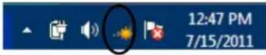
2 In the wireless network options box, highlight the Wireless Network name (SSID) you gave your wireless network in Step 3 of the Setup Wizard. If you did not change the Wireless Network (SSID), select the default name Zoom. If you want to automatically connect to the Wireless-N 4-port Router, click the Connect Automatically box. Then click Connect.
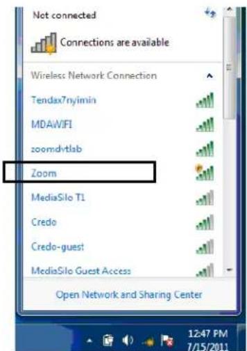
- If you enabled security in Step 3 of the Setup Wizard, enter the security key in the next dialog box and click Connect.
- Otherwise if your desired network is unsecured, in the message box select Connect Anyway.
When you click on the wireless network option box, Windows will scan for available networks. More than one wireless network may appear in the list. These are other wireless networks that are within range of your network. Your neighbors, for instance, may be within range of your network. Each wireless network has a channel associated with it. We recommend there be at least a five-channel difference between your network and those of your neighbors. Having less than a five-channel difference may result in interference with your connection. By default, the Wireless-N 4-port Router uses channel 10. If you need to change this channel, you must do so using the Wireless Setup page of the Zoom Configuration Manager. After logging in, select Wireless from the left-hand menu. On the Wireless page you can select a new channel from the drop-down menu.
To disconnect from the current network:
1 Left-click the wireless network icon in the notification area of the Windows taskbar.
2 Right-click your network ID and select Disconnect.
Connecting a Windows Vista Computer with Built-in Wireless Capabilities
1 From the Start menu select Connect to.
2 In the Connect to a network dialog box, highlight the Wireless Network name (SSID) you gave your wireless network in Step 3 of the Setup Wizard. If you did not change the Wireless Network (SSID) select the default name Zoom and click Connect.
- If your desired network is secured, in the next dialog box enter the security key or password and click Connect.
- If your desired network is unsecured, in the message box select Connect Anyway.
When you click on the wireless network option box, Windows will scan for available networks. More than one wireless network may appear in the list. These are other wireless networks that are within range of your network. Your neighbors, for instance, may be within range of your network. Each wireless network has a channel associated with it. We recommend there be at least a five-channel difference between your network and those of your neighbors. Having less than a five-channel difference may result in interference with your connection. By default, the Wireless-N 4-port Router uses channel 10. If you need to change this channel, you must do so using the Wireless Setup page of the Zoom Configuration Manager. For instructions on how to log in to the Zoom Configuration Manager, see page 7. After logging in, select Wireless from the left-hand menu. On the Wireless page you can select a new channel from the drop-down menu.
3 In the Successfully connected to [desired network] dialog box, you have three options. You can:
- Select Save the network and Start this connection automatically if you always want to connect to the same network. Then click Close. The next time you start your computer you will automatically connect to the selected network.
- Select Save the network and clear the Start this connection automatically check box if you don't want to automatically connect to this network every time you start your computer but you will want to connect in the future. Click Close to display the Select a location . . . dialog box where you choose a location. Windows Vista automatically applies the correct network security settings. If the User Account Control dialog box appears, click Continue.
- Click Close to complete the connection procedure. Select this option if you are connecting to this network only one time.
To disconnect from the current network:
1 From the Start menu, select Connect to.
2 In the Disconnect or Connect to another network dialog box, select the current network and click Disconnect.
3 In the Are You Sure? message box, click Disconnect again.
4 In the next dialog box, you can connect to another network or click Close to complete the disconnect procedure.
Connecting a Windows XP Computer with Built-in Wireless Capabilities
1 On your Windows desktop, click the Wireless Network Icon in the System Tray.
2 Windows will automatically scan for available wireless networks in your area. Any compatible networks within range will appear in the Available networks list. Double-click the Wireless Network name (SSID) you gave your wireless network in Step 3 of the Setup Wizard. If you did not change the Wireless Network name (SSID), select the default name Zoom.
- If you enabled security in Step 3 of the Setup Wizard, enter the security key in the next dialog box and click Connect.
- Otherwise if your desired network is unsecured, in the message box select Connect Anyway.
When you click on the wireless network option box, Windows will scan for available networks. More than one wireless network may appear in the list. These are other wireless networks that are within range of your network. Your neighbors, for instance, may be within range of your network. Each wireless network has a channel associated with it. We recommend there be at least a five-channel difference between your network and those of your neighbors. Having less than a five-channel difference may result in interference with your connection. By default, the Wireless-N 4-port Router uses channel 10. If you need to change this channel, you must do so using the Wireless Setup page of the Zoom Configuration Manager. For instructions on how to log in to the Zoom Configuration Manager, see page 7. After logging in, select Wireless from the left-hand menu. On the Wireless page you can select a new channel from the drop-down menu.
To disconnect from the current network:
1 On your Windows desktop, click the Wireless Network Icon in the System Tray.
2 Select your Network ID. And click on Disconnect.
Connecting a Wireless-enabled Computer or Device (including the iPhone® or other cellular phones, the iPod Touch®, etc.) to the Wireless-N 4-port Router
1 Go to the wireless-enabled computer or device that you want to add to the network. The device should have software that will let it perform a site search to scan for available wireless networks in your area. You may have to click on something similar to Settings and then Wi-Fi. When the Wireless Network name (SSID) that you gave the Wireless-N 4-port Router Step 3 of the Setup Wizard. If you did not change the Wireless Network name (SSID) select the default name Zoom. Select it as the network you want to use to connect to the Internet.
If you enabled security in Step 3 of the Setup Wizard enter the security key when prompted by your device.
Tip!
If you need help, refer to the documentation that came with your wireless device.
There are several site scan issues you should be aware of:
More than one wireless network may appear in the list. These are other wireless networks that are within range of your network. Your neighbors, for instance, may be within range of your network. Each wireless network has a channel associated with it. We recommend there be at least a five-channel difference between your network and those of your neighbors. Having less than a five-channel difference may result in interference with your connection. By default, the Wireless-N 4-port Router uses channel 10. If you need to change this channel, you must do so using the Wireless Setup page of the Zoom Configuration Manager. For instructions on how to log in to the Zoom Configuration Manager, see page 7. After logging in, select Wireless from the left-hand menu. On the Wireless page you can select a new channel from the drop-down menu.
2 Test your wireless connections. From each computer or device that you set up, open your Web browser (for instance, Internet Explorer, Firefox, or Chrome) and try to connect to a familiar Web address.
If you connect successfully, you are ready to browse the Web!
To disconnect from the current network:
1 On your wireless device or computer, find the wireless network connection option (similar to the process of adding your device or computer to the network).
2 Click or highlight Zoom.
3 Select or click on Disconnect or similarly-named button.
Connecting a Computer with a Wireless Adapter to the Wireless-N 4-port Router
1 Go to the computer that is set up with a wireless adapter that you want to add to the network. The computer should have software that will let it perform a site search to scan for available wireless networks in your area. When the Wireless Network name (SSID) that you set in Step 3 of the Setup Wizard of your Wireless-N 4-port Router's wireless network appears in the list select it as the network you want to use to connect to the Internet. If you did not change the Wireless Network name (SSID) in Step 3 select the default name Zoom.
Tip!
For most wireless adapters, you will use its wireless configuration manager software and click a Scan button or select a Site Scan, Scan Networks, or other similarly named tab to do a site search. If you need help, refer to the documentation that came with your wireless adapter.
There are several site scan issues you should be aware of:
If you are trying to connect to a wireless network that already has security enabled, your wireless adapter might not recognize what type of security is on the network. You may need to manually set up the security for your adapter. If you need help, refer to the documentation that came with your wireless adapter.
Windows 7, XP, and Vista users: If you installed a wireless adapter on a Windows 7, XP, or Vista computer, Windows may try to automatically configure the adapter (rather than let you use the software provided with the wireless adapter). You will know this is happening because you will be prompted with a message about one or more wireless networks being available.
You will also be able to click a link to open the Wireless Network Connection Properties dialog box. If this happens, click the link, clear the Use Windows to configure my wireless network settings check box, and then click OK. You can then use the software provided with your wireless adapter without interruption from Windows.
More than one wireless network may appear in the list. These are other wireless networks that are within range of your network. Your neighbors, for instance, may be within range of your network. Each wireless network has a channel associated with it. We recommend there be at least a five-channel difference between your network and those of your neighbors. Having less than a five-channel difference may result in interference with your connection. By default, the Wireless-N 4-port Router uses channel 10. If you need to change this channel, you must do so using the Wireless Setup page of the Zoom Configuration Manager. For instructions on how to log in to the Zoom Configuration Manager, see page 7. After logging in, select Wireless from the left-hand menu. On the Wireless page you can select a new channel from the drop-down menu.
2 Test your wireless connections. From each desktop or notebook computer that you set up, open your Web browser (for instance, Internet Explorer or Firefox) and try to connect to a familiar Web address.
If you connect successfully, you are ready to browse the Web!
To disconnect from the current network:
1 On your computer that has a wireless adapter, find the wireless network connection option (similar to the process of adding your computer to the network).
2 Click or highlight the Wireless-N 4-port Router's Network ID.
3 Select or click on Disconnect or similarly-named button.
In the unlikely event you need to make changes to the Wireless-N 4-port Router's advanced settings please see Chapter 7, Using the Configuration Manager's Advanced Program.
Otherwise, your set up is complete. Congratulations!
Using the Configuration Manager's Advanced Program
Most users will not need to manually set up their Router. In the unlikely event that you do, you can use the Configuration Manager's Advanced program to change the Router's default settings.
Changing Default Settings
Here are some reasons why you might want to use the Advanced program to change the Router's default settings.
You want to block access to certain URLs or set up Scheduling usage rules. See The URL Blocking Page on page 60 and The Schedule Rule and Schedule Rule Setting Pages on page 71 for details.
You want to hide the SSID name so other network users cannot see your wireless network. See The Wireless Settings Page on page 48 for details.
You want to change Router settings to establish a firewall to guard against unauthorized wireless access to your network. See The MAC Address Control Page on page 61 for details.
You want to set up a Virtual Server or DMZ so that your games or gaming consoles can access the Internet through your Router's firewall. See Configuring Forwarding Rules on page 52 for details.
You want to set up QoS on your Router. See The QoS Rule Page on page 67 for details.
You want to back up Router settings that you made using the Configuration Manager. See The Backup Setting Dialog on page 75 for details.
Online Help
The Advanced program provides both online and context-sensitive help that guides you in changing the settings on each menu.
To access online help, click [HELP] on the menu's Toolbar. Each [HELP] page describes the fields on the active page and, when applicable, the required or recommended entries.
The context-sensitive help automatically displays a question mark to the right of the cursor, then opens a message box in the left pane of the page. The message box contains text that describes the active field and its required or recommended entry.
Launching the Configuration Manager's Advanced Program
1 Turn on your computer and Router, then launch your Web browser.
2 In the Web browser address bar, type the Router's default IP address, http://192.168.2.1 and then click Enter to launch the Configuration Manager.
When the Configuration Manager's MAIN MENU opens, it displays a Status page that summarizes the basic settings and current values for your setup.
3 On the Toolbar, type the login password -- admin is the default password -- in the System Password field, and then click Login.

4 Click Advanced on the Toolbar to launch the Advanced program.

5 On the Basic Settings page, click one of the Toolbar buttons (Basic Settings, Forwarding Rules, Security Settings, Advanced Settings, or Toolbox).
The corresponding window opens. Each window contains a description of the configuration options at center and a configuration menu on the left pane.
Configuring Basic Settings
The Basic Settings page lists the four configuration menus on the left pane and provides a description of the configuration menus at center.
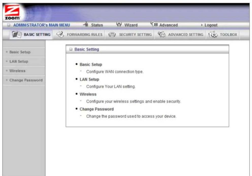
The Basic Setup Page
You can use the Basic Setup page to configure your WAN setup. Most users should configure their WAN settings using the Router's built in setup wizard.
Note: The following image depicts the fields that the program displays when Dynamic IP Address is selected as the WAN Type. The fields will differ for each WAN Type. See the online help for a description of each WAN Type and its corresponding fields
![ADMINISTRATOR's MAIN MENU Status Wizard Advanced Logout BASIC SETTING FORWARDING RULES SECURITY SETTING ADVANCED SETTING TOOLBOX Basic Setup [HELP] Item Setting WAN Type Dynamic IP Address Change... Host Name (optional) Enable MAC Cloning 00-50-18-64-49-FF Clone MAC (optional) Connection Control Auto Reconnect(always-on) MTU 1500 NAT Disable ICMP Proxy Enable Save Undo Virtual Computers...](/content/2026/05/857512/images/069d1d2447e4dca093cf788e9b7708154ea71854641a586a43d591f9de5a86bb.jpg)
WAN Type
You can choose from the dropdown menu, based on the WAN connection type that your service provider supports.
Host Name (optional)
Enter the host name if provided by your ISP.
Enable MAC Cloning (optional)
This function can change the WAN MAC Address of this device. Use if your ISP requires it.
Connection Control
AutoReconnect (always-on) is set by ddefault.
MTU (Maximum Transmission Unit)
Default is 1500.
NAT
On by default.
IGMP Proxy
Allows multicast IGMP, for example IPTV service to pass through NAT from the WAN side.
Click Save to save changes.
Click Undo if you need to reset the settings you changed on this page.
Virtual Computers: Allows you to set up one-to-one mapping of multiple global IP address and local IP address. Also known as "Static 1-1 NAT" where each LAN host can have a direct and fixed mapping to a global address.
Global IP: Enter the global IP address assigned by your ISP.
Local IP: Enter the local IP address of your LAN PC corresponding to the global IP address.
The LAN Setup Page
You can use the LAN Setup page to configure your LAN settings.
![ADMINISTRATOR'S MAIN MENU Status Wizard Advanced Logout BASIC SETTING FORWARDING RULES SECURITY SETTING ADVANCED SETTING TOOLBOX LAN Setup [HELP] Item Setting LAN IP Address 192.168.2.1 Subnet Mask 255.255.255.0 DHCP Server Disable Enable Lease Time 1440 Minutes IP Pool Starting Address 100 IP Pool Ending Address 200 Domain Name Save Undo More>> Clients List... Fixed Mapping...](/content/2026/05/857512/images/b939a1148c80a3a8e0658e9ae5944682269ceb3660642ccf5fa2bdc45ed54f6f.jpg)
LAN IP Address
This is the address of this device. The LAN IP address is always the default gateway for devices on the LAN. Note: if you change the LAN IP address you will need to log back into the Router using the new LAN address.
Subnet Mask
The Router's subnet mask address. Most users will not need to change this.
DHCP Server
By default DHCP Server is enabled; this allows the Router to assign IP addresses to the devices connected to your Wireless-N 4-port Router. Disable the DHCP Server if you wish to use static IP addresses on your network or you have another device on your network that you want to use as your DHCP server
When DHCP Server is enabled you will need to have the Subnet Mask, Lease Time, IP Pool Starting Address, and IP Pool Ending Address for your network which, by default are all entered.
Lease Time
The maximum amount of time, in minutes, that a network device will have the temporary IP address before a new one is issued by the Router's DHCP server.
IP Pool Starting Address
The first IP address of a range that you specify using the Start and End IP Address settings. Your Router's DHCP server will assign the IP addresses in this range at random to the computers and devices in your network. Note that the Start and End IP Addresses must both be in the same subnet as the IP Address, above.
IP Pool Ending Address
The last IP address of a range that you specify using the Start and End IP Address settings. Your modem's DHCP server will assign numbers from this range at random to the computers and devices in your network. By default the DHCP server has 253 addresses available to assign. Note that the Start and End IP Addresses must both be in the same subnet as the IP Address, above.
Domain Name (optional)
This information will be passed to the client. Some ISPs require you to configure this item, such as @Home.
More>> When you click this button, you get the following fields:
Primary DNS
This is the Domain Name System (DNS) server's IP address. Your service provider supplies this address, if needed. Most users should not need to enter a DNS value.
Secondary DNS
This is the IP address of an alternate Domain Name System (DNS) server. Your service provider supplies this address, if needed.
Primary WINS (optional)
This is a Microsoft implementation that serves as a central mapping of host names to network addresses. WINS also provides the functionality of keeping the client names unique on the network.
Secondary WINS (optional)
This is a Microsoft implementation that serves as a central mapping of host names to network addresses. WINS also provides the functionality of keeping the client names unique on the network.
Gateway
This is the IP address of the router that serves as the access point to the Internet. This IP address might be your ISP's gateway's IP address or the IP address of your cable or ADSL modem.
Click Save to save changes.
Click Undo if you need to reset the settings you changed on this page.
Clients List: Lists the current mapping of the IP and MAC address for each DHCP client.
Fixed Mapping
Clicking on the Fixed Mapping button brings you to the Fixed Mapping page. On this page you can set your DHCP server to always assign the same IP address to a computer connected to the Router. Otherwise the IP address assigned by the DHCP server could change over time. Fixed Mapping allows you to assign the same IP address to your computer every time. This is important if you are setting up a DMZ, Virtual Server, or Port Forwarding rule to be used with online gaming.
To setup Fixed Mapping select the computer you wish to use the same IP address from the DHCP Clients drop down list. Select 1 from the ID drop down list and click the Copy to button to copy the MAC address into the table. Now enter the IP address that you want the computer to always be assigned and check the Enable box. This assigned "fixed" address should be outside of the current DHCP pool. The default pool is 100-200. So any fixed IP outside of this range should work fine and avoid any possibility of the router assigning a specified "fixed" address to another LAN host.
Click Save and now the computer you selected will always be assigned the same IP address.
The Wireless Settings Page
You can use the Wireless Settings page to configure your wireless LAN setup. If you want to change the default values, refer to the descriptions below for each item.
![ADMINISTRATOR's MAIN MENU Status Wizard Advanced Logout BASIC SETTING FORWARDING RULES SECURITY SETTING ADVANCED SETTING TOOLBOX Basic Setup LAN Setup Wireless Change Password Wireless Setting [HELP] Item Setting ► Wireless Enable ● Disabled ► SSID (Wireless Network Name) Zoom ► Wireless Mode B/G/N mixed mode ▼ ► Bandwidth 40MHz ▼ ► Broadcast Wireless Network Name Enable ● Disable ► Wireless Schedule Rule [00]None ○ Enable ● Disable ► Channel 10 ▼ ► WDS Configure... ► WPS Configure... ► Ethernet Client Mode Configure... ► Security None ▼ Save Undo Wireless Client List...](/content/2026/05/857512/images/3ecf74f6e4bcb7d90553d7c00137fc264aa8312ed4a64d283f74b39c024eac55.jpg)
Wireless
Accept the default: Enable. Click the Disable checkbox only if you do not want wireless clients to access your network.
SSID (Wireless Network Name)
Refers to the Service Set Identifier for your device. By default, the Wireless Network Name for the Wireless-N 4-port Router is Zoom. You can change the SSID to a name of your choice. The SSID can be up to 32 alphanumeric characters. If you change the name, make sure that all devices on your network use the new SSID as the access point.
Wireless Mode
Accept the default, B/G/N mixed if the client devices on your network use various wireless standards. Otherwise, select the wireless standard used by all wireless devices on your network.
Bandwidth
Specify radio frequency bandwidth, either 20MHz or 40MHz, that the Router will use.
Broadcast Wireless Network Name
To hide your wireless network's SSID name, which disables automatic broadcasting of the SSID and makes the wireless access point (your Router) invisible to wireless clients on the network, click the Disable radio button.
Wireless Schedule Rule
When enabled, the device will turn wireless ON and OFF according to the Schedule Rule. Click Enable. Then click Schedule Setting to open the Schedule Rule page.
Channel
Refers to the wireless network channel assigned to your LAN. By default, the Wireless-N 4-port Router uses channel 10. You may need to change the channel number of the Router if you experience a lot of interference from other wireless devices in your area.
WDS
A Wireless Distribution System (WDS), also called a bridge, expands the area covered by a wireless network by using multiple Access Points (APs) connected wirelessly. Refer to Chapter 4, Setting up the Wireless-N 4-port Router as a Repeater for instructions on how to set up the Wireless-N 4-port Router as a repeater in either Hybrid mode or WDS Only mode.
WPS
Click WPS Setup to launch the WiFi Protected Setup (WPS) Setup program. For instructions, please refer to Appendix C: Setting up your Network using WPS.
Ethernet Client Mode
As an Ethernet Client, the Router allows a device with an Ethernet port, such as a gaming console or HDTV to join an existing wireless network. To use the Router as an Ethernet Client, please refer to Chapter 3, Ethernet Client Mode.
Security
Select from the following options:
- WPA2/WPA (Recommended): Most users should select the WPA2/WPA option. When you select this option, the Security Key field appears.
- Security Key: Please input 8 to 63 characters as your Security key.
- WEP: You must select this option if you have devices on your network that only support WEP. Otherwise we recommend WPA2/WPA. (Devices that only support WEP include older handheld game consoles, older MAC notebooks, and very old Windows notebooks.)
| Field Entry | |
| Encryption WEP Key 1, 2, 3, 4 | You can choose to either use WEP 128 bit encryption or WEP 64 bit encryption. The difference is 128 bit is more secure and 64 bit is faster. We recommend selecting 64 bit.In ASCII format, if you chose a 64-bit key length, 5 ASCII characters are required. Write the 5-ASCII-character key in the space below for future reference, and then enter it in the Key 1 box.____In ASCII format, if you chose a 128-bit key length, 13 ASCII characters are required. Write the 13-ASCII-character key in the space below for future reference, and then enter it in the Key 1 box.____ |
- None (the default): Select this if you don't plan to use wireless security or if all the devices on your network support WPS (WiFi® Protected Setup) and you wish to use WPS to set up wireless security. We
recommend using the Setup Wizard with the options above to set up security for your Wireless-N 4-port Router. However, if you choose to use WPS, please refer to Appendix C: Setting up Your Network Using WPS.
Click Save to save changes.
Click Undo if you need to reset the settings you changed on this page.
Wireless Client List: Click to view all clients connected to the Wireless-N 4-port Router.
The Change Password Page
You can use this page to change your login password. To view or change configuration settings, you must enter a password. Your Router has a default password (admin) that was set by the factory and that you used to access the Configuration Manager initially. To safeguard your configuration, particularly if you make changes, we recommend that you change the login password.
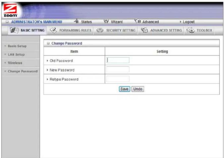
Note: If you forget the new password, you won't have access to the Configuration Manager and will need to restore the device to its factory settings thus losing any changes you made to your Router's configuration. To avoid this problem, we recommend that you write the new password and save it in a convenient location.
Configuring Forwarding Rules
If you are using your Router for gaming, you may need to make changes to the Router's firewall setting for the game to work. This is done by setting up a DMZ or virtual server, or using port triggering so that the Router's firewall won't block the other players from your system during your gaming. The main difference between the three methods is the amount of access someone has to your system.
A virtual server will allow access to your computer or gaming station on certain ports. A port is a channel that is used by applications (such as games) for communication. For example, the directions for the game you want to play over the Internet might tell you to open up port 6000.
Port triggering works by sensing when data is sent out on the predetermined outgoing port and then automatically opening up the corresponding incoming port(s). It will automatically forward the traffic on the incoming port to the computer that accessed the outgoing port. If your game uses one port to send outgoing data and a different port (or ports) for incoming data, you may want to use port triggering. The advantage of port triggering is that it is more secure than setting up a virtual server since the incoming port is only open when you are using it, and since it tracks which computer sent the outgoing data. port triggering can also be easier to set up because you do not need to know the IP address of your gaming station. The disadvantage of port triggering is that only 1 host can be accessing the port at one time, so if you have two computers or game stations playing the same game on your network you will need to use a virtual server or DMZ.
A DMZ differs from a virtual server in that it allows access on all ports of the computer. Because of this, DMZ's arc less secure and should be used with caution on your computer. However DMZ's work well with your gaming stations since security is not as much of an issue for gaming stations as it is for computers.
Some games support UPnP. If your game supports UPnP then you do not need to set any forwarding rule since UPnP will automatically set up the Router to work with the game.
You can use the Forwarding Rules page to configure the options mentioned above, for allowing access to devices behind your Router.
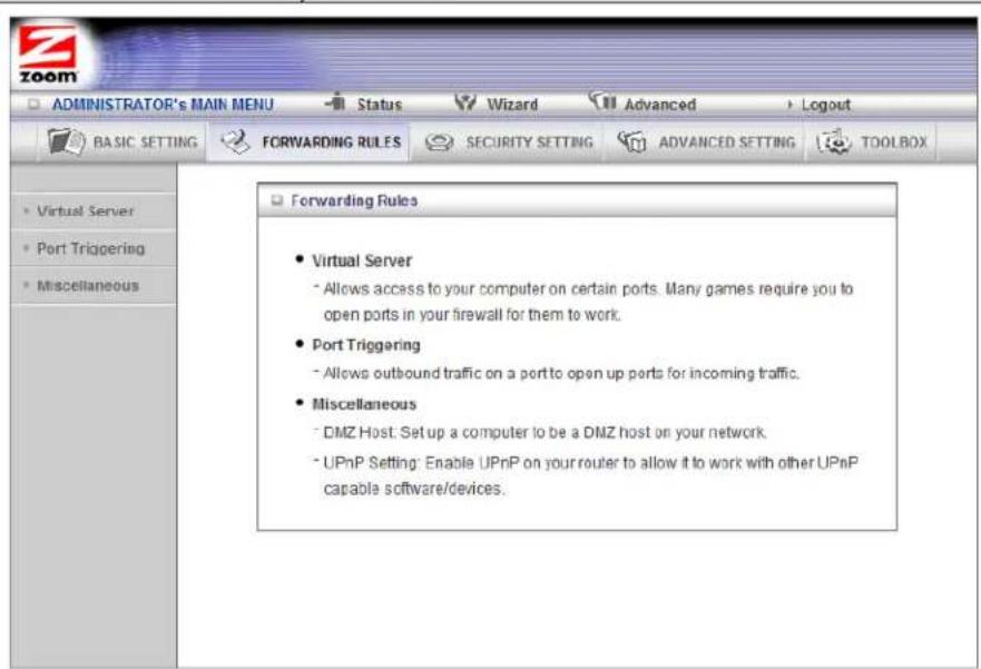
The Virtual Server Page
You can use the Virtual Server page to configure a virtual server.
Because your Router's NAT firewall filters out unrecognized packets to protect your network, all computers behind this product are invisible to the outside world. If you want, you can make some of them accessible by enabling Virtual Server mapping.
A virtual server will allow access to your computer on certain ports. A port is like a channel that is used by applications (such as games) to communicate on. For example, the directions for the game you want to play over the Internet might tell you to open port 6000 on the router.
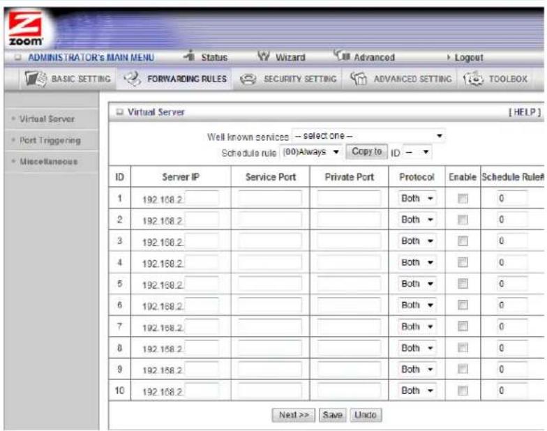
Server IP
This is the IP Address of the computer or gaming device that you want to allow access to. If you do not know the IP address you can look it up by selecting Basic Settings > LAN Setup, then clicking on Client List. To make this virtual server permanent, then you should set up a fixed mapping to your computer or gaming device on the LAN Setup page. Doing this ensures that your computer will keep the same IP address.
Service Port
This is the port number you want to allow access to your computer on.
Private Port
Usually the private port should be set to the same port as the service port. However if you want to hide the port you are using internally from the outside world you may set a private port. Data will come in over the service port and the Router will switch the port used by the data to the private port. Computers on your network will see the data on the private port but users outside your firewall will see the data on the service port.
Protocol
Select UDP, TCP, or Both depending on what type of protocol your game or application uses.
Enable
Click to enable the Virtual Server.
Schedule Rule#
You can enable your virtual server for certain periods of time by assigning it a Rule #. You must first set up the appropriate Scheduling Rule. See The Schedule Rule and Schedule Rule Setting Pages on page 71 for more information.
For example, if you have an FTP server (port 21) at 192.168.2.5, a Web server (port 80) at 192.168.2.6, and a game at 192.168.2.7, then you need, at minimum, to specify the following mapping.
| ID | Server IP | Service Port | Private Port | Enable |
| 1 | 192.168.2.5 | 21 | 21 | Yes |
| 2 | 192.168.2.6 | 80 | 80 | Yes |
| 3 | 192.168.2.7 | 5000 | 5000 | Yes |
The Port Triggering Page
Port triggering opens incoming ports when your computer is using a specified outgoing port for specific traffic. This provides a way for you to automate setting up a Virtual Server with some applications. You can use the Port Triggering page to configure which packets are allowed access.
![ADMINISTRATOR's MAIN MENU Status Wizard Advanced Logout BASIC SETTING FORWARDING RULES SECURITY SETTING ADVANCED SETTING TOOLBOX Virtual Server Port Triggering Miscellaneous Port Triggering [HELP] Popular applications -- Select one -- Copy to ID -- ID Trigger Incoming Ports Enable 1 ______________________________ 2 ______________________________ 3 ______________________________ 4 ______________________________ 5 ______________________________ 6 ______________________________ 7 ______________________________ 8 ______________________________ Save Undo](/content/2026/05/857512/images/a905a9f9d3a263ea84fabc582c335f05f8911b23ed87893631b4e9cfdeb91da3.jpg)
Trigger
The outbound port number used by the application.
Incoming Ports
When the outbound trigger packet is detected, the router opens the specified inbound ports and the inbound packets sent to the specified port numbers are allowed to pass through the firewall.
Enable
Enables access for the specified application.
Click Save to store your selection or Undo to remove the entry.
![ADMINISTRATOR'S MAIN MENU Status Wizard Advanced Logout BASIC SETTING FORWARDING RULES SECURITY SETTING ADVANCED SETTING TOOLBOX Virtual Server Port Triggering Miscellaneous Port Triggoring [HELP] Popular applications - Select one - Copy to ID - ID Trigger Incoming Ports Enable 1 2 3 4 5 6 7 8 Save Undo](/content/2026/05/857512/images/ff6a3c488cfaf69599fa6a4db622df91e93d4f962ca206c9c033582956f828a0.jpg)
The Miscellaneous Page
The Miscellaneous Page lets you set up and enable a DMZ Host on your network, and enable UPnP settings for software and devices. In this way, specific ports can open for incoming traffic that must pass through your firewall. You can also enable IGMP on this page in the unlikely event that your service provider is using it.
![ADMINISTRATOR's MAIN MENU Status Wizard Advanced Logout BASIC SETTING FORWARDING RULES SECURITY SETTING ADVANCED SETTING TOOLBOX Virtual Server Port Triggering Miscellaneous Miscellaneous Items [HELP] Item Setting Enable IP Address of DMZ Host 192.168.2 Super DMZ(IP Passthrough) — Select one — Copy UPnP setting ✓ Xbox Support ✓ Save Undo](/content/2026/05/857512/images/d21c3c766d0f799fb5e3ed9a7b84ca5f37e8c34865b2153c37a66660dfcd50f5.jpg)
IP Address of DMZ Host
A DMZ (Demilitarized Zone) Host is a host without the protection of the router's firewall. It allows a computer or gaming system to be exposed to unrestricted two-way communication for Internet games, video conferencing, Internet telephony and other special applications. Use caution when using a DMZ because your router's firewall no longer protects the computer that is set up as a DMZ.
Super DMZ (IP Passthrough)
The LAN host specified by a Super DMZ will acquire the router's WAN IP and communicate using this IP. There is no NAT translation of the IP address from this one computer. All other LAN hosts will keep their LAN addresses and use NAT translation. Also, any unsolicited incoming packets will be forwarded to this "Super DMZ". The difference between a Super DMZ and a normal DMZ is the Super DMZ's LAN host will use the router's WAN IP address.
UPnP setting
This feature is enabled by default. Games and applications that are UPnP compatible will automatically open ports for you on your Router.
Xbox® Support
Enabled by default. Allows connection to an Xbox.
Configuring Security Settings
The Security Settings page lists six configuration menus on the left pane and provides a description of the configuration menus at center.
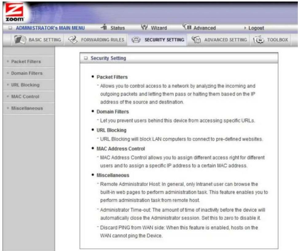
Packet Filters Page
Packet Filtering allows you to control what packets are allowed to pass through the Router. Outbound Packet filters control outbound packets and Inbound Filtering controls packets coming from the Internet. Inbound Filters applies only to packets going to a Virtual Server, DMZ, or Super DMZ. Most users will not need to setup Packet Filtering.
When you click on Packet Filters from the left-side menu, it takes you to the Outbound Packet Filtering page. If you need to set up an Inbound Filter, click on Inbound Filter button at the bottom of the page.
![ADMINISTRATOR's MAIN MENU Status Wizard Advanced Logout BASIC SETTING FORWARDING RULES SECURITY SETTING ADVANCED SETTING TOOLBOX Outbound Packet Filter [HELP] Item Setting Outbound Filter Enable Allow all to pass except those match the following rules. Deny all to pass except those match the following rules. Schedule rule (00)Always Copy to ID ID Source IP Destination IP:Ports Enable Schedule Rule# 1 0 2 0 3 0 4 0 5 0 6 0 7 0 8 0 Save Undo Inbound Filter... MAC Level...](/content/2026/05/857512/images/06039ce2b12a265be0cd2e843d0b02207a47325a8946fc46c3741448719136d1.jpg)
Filtering Policies
You can select one of the two filtering policies. You can either allow or deny data that matches the filtering rule to pass.
Filtering Rules
You can specify eight rules for each direction: inbound or outbound. For each rule, you can define the following:
Source IP address
Destination IP address
Destination Port
Schedule Rule#
For the Source or Destination IP address, you can define a single IP address (4.3.2.1). An empty field implies any IP address.
For Destination Port, you can define a single port (80) or a range of ports (1000-1999). No prefix indicates both TCP and UDP are defined. Leaving this empty implies that all port addresses apply.
Each Rule can be enabled or disabled individually.
You can use packet filters with scheduling rules for more access control flexibility.
The Domain Filters Page
You can use the Domain Filters page to enable or deny user access to specified URLs. Domain filtering and URL Blocking perform similar functions. The major difference between Domain Filtering and URL Blocking is that Domain Filtering filters an entire Domain (.com, .org) where URL Blocking will block specific WEB sites based on a single word or an entire URL and everything in between. In other words, Domain Filtering can block a specific web site, whereas URL Blocking can block hundreds of web sites by specifying a keyword.
![ADMINISTRATOR'S MAIN MENU Status Wizard Advanced Logout BASIC SETTING FORWARDING RULES SECURITY SETTING ADVANCED SETTING TOOLBOX Packet Filters Domain Filters URL Blocking MAC Control Miscellaneous Domain Filter [HELP] Item Setting Domain Filter Enable Log DNS Query Enable Privilege IP Addresses Range From 0 To 0 Block Setting Blacklist Whitelist Schedule rule (00)Always Copy to ID ID Domain Suffix Action Enable Schedule Rule# 1 ________ Log 0 2 ________ Log 0 3 ________ Log 0 4 ________ Log 0 5 ________ Log 0 6 ________ Log 0 7 ________ Log 0 8 ________ Log 0 9 ________ Log 0 10 * (all others) Log - 0 Save Undo](/content/2026/05/857512/images/01b567921ac44ce11d1a6462b208fc97f92cad87ad75172c5db1e6930948b6bd.jpg)
Domain Filter
Click Enable to prevent users behind this device from accessing specific URLs.
Log DNS Query
Check if you want to log the action when someone accesses, or tries to access, the specific domain.
Privilege IP Address Range
Domain filtering rules do not apply to IP addresses in this range.
Domain Suffix
The suffix of the restricted URL; for example, xxx.com.
Action
Check log to record the attempted access.
Enable
Click the checkbox to enable a rule.
Schedule Rule #
The Rule # set on the Schedule Rule page.
Click Save to save changes.
Click Undo if you need to reset the settings you changed on this page.
The URL Blocking Page
You can use the URL Blocking page to block LAN computers from connecting to limit their access to specific websites. The major difference between Domain Filtering and URL Blocking is that Domain Filtering filters an entire Domain (.com, .org) where URL Blocking will block specific WEB sites based on a single word or an entire URL and everything in between. In other words, Domain Filtering can block a specific web site, whereas URL Blocking can block hundreds of web sites by specifying a keyword.
![ADMINISTRATOR's MAIN MENU Status Wizard Advanced Logout BASIC SETTING FORWARDING RULES SECURITY SETTING ADVANCED SETTING TOOLBOX Packet Filters Domain Filters URL Blocking MAC Control Miscellaneous URL Blocking [HELP] Item Setting URL Blocking Enable Block Setting Blacklist Whitelist Schedule rule (00)Always Copy to ID ID URL Enable Schedule Rule# 1 2 3 4 5 6 7 8 9 10 Save Undo](/content/2026/05/857512/images/039be37067de778527a72b917aee2d4203a5e187814c79dcd4e7247381f2b0ec.jpg)
URL Blocking Enable
Check if you want to enable URL Blocking.
URL Blocking Setting
Select Blacklist to block access to any words or URLs that you specify. Select Whitelist to allow access only to the URLs that you specify.
URL
If any part of the Website's URL matches the pre-defined word, the connection will be blocked if Blacklist is set, or allowed if Whitelist is set. For example, if you set up blacklisting, you can use the pre-defined word, sex, to block all website URLs that contain the pre-defined word, sex.
Enable
Click the checkbox to enable each rule.
Schedule Rule #
Click the checkbox to enable each rule.
Click Save to save changes.
Click Undo if you need to reset the settings you changed on this page.
The MAC Address Control Page
You can use the MAC Address Control page to provide an added layer of security to your Wireless-N 4-port Router. MAC Address control is used to define connection and association rights for clients whose IP and MAC addresses are specified. Click on the HELP button page for a detailed explanation including examples for setting up MAC address control.
![ADMINISTRATOR'S MAIN MENU Status Wizard Advanced Logout BASIC SETTING FORWARDING RULES SECURITY SETTING ADVANCED SETTING TOOLBOX MAC Address Control [HELP] Item Setting MAC Address Control Enable Connection control Wireless and wired clients with C checked can connect to this device; and allow unspecified MAC addresses to connect. Association control Wireless clients with A checked can associate to the wireless LAN; and allow unspecified MAC addresses to associate. Note: Association control has no effect on wired clients. DHCP clients --- Select one --- Schedule rule (00)Always Copy to ID -- ID MAC Address IP Address C A Schedule Rule# 1 192.168.2 0 2 192.168.2 0 3 192.168.2 0 4 192.168.2 0 << Previous Next >> Save Undo](/content/2026/05/857512/images/f6890889cdf55c7b9f00fdcede98d649214a8eb0359772282cffa1253bd31344.jpg)
MAC Address Control
Check Enable to enable MAC Address Control. All of the settings on this page will take effect only if Enable is checked.
Connection Control
Check Connection Control to specify which wired and wireless clients can connect to this device. If a client is denied a connection to this device, then that client is also denied Internet access. Choose allow or deny to indicate which clients can connect to this device.
Association control
Check Association control to specify which wireless clients can associate to the wireless LAN. If a client is not allowed to associate to the wireless LAN, then the client can't send or receive any data via this device. Choose allow or deny to indicate which clients can associate to the wireless LAN. If selected, the specified wireless client will obtain any radio connection to the access point.
DHCP clients
Displays a list of DHCP computers that are currently connected to the Router. Select a client from the menu then copy to the selected ID. The client IP and MAC addresses arc written in the fields below the menus.
MAC Address
Indicates a specific client's MAC address.
IP Address
Expected IP address of the corresponding client. Leave it blank if you don't want to assign a specific IP address to the corresponding client.
Schedule Rule #
The Rule # set on the Schedule Rule page.
Click Save to save changes.
Click Undo if you need to reset the settings you changed on this page.
The Miscellaneous Page
You can use the Miscellaneous Items page to enable additional security features.
![ADMINISTRATOR'S MAIN MENU Status Wizard Advanced Logout BASIC SETTING FORWARDING RULES SECURITY SETTING ADVANCED SETTING TOOLBOX Packet Filters Domain Filters URL Blocking MAC Control Miscellaneous Miscellaneous Items [HELP] Item Setting Enable Remote Administrator Host / Port 0.0.0.0 / 88 Administrator Time-out 300 seconds (0 to disable) Discard PING from WAN side SPI mode ✓ DoS Attack Detection ✓ VPN PPTP Pass-Through ✓ VPN L2PT Pass-Through ✓ VPN IPSec Pass-Through ✓ Save Undo](/content/2026/05/857512/images/382b54445a24a94d97dcb65ed74ada9ca7fb9ae294041c5a1ce34ae976d7c2c5.jpg)
Please refer to the online help for details about each of the menu items.
Configuring Advanced Settings
The Advanced Settings page lists eight menus on the left pane and provides a description of the configuration menus at center.
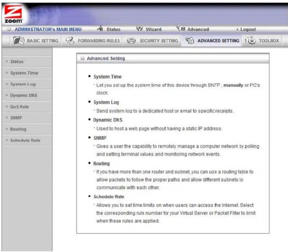
The System Time Page
You can use the System Time page to set and synchronize your Router with the local time zone, the Time Server and your PC. You may use either a NTP server, your local PC or manually set the time in the Router.
![ADMINISTRATOR's MAIN MENU Status Wizard Advanced Logout BASIC SETTING FORWARDING RULES SECURITY SETTING ADVANCED SETTING TOOLBOX System Time [HELP] Item Setting System Time Monday, June 01, 2009 12:05:47 AM Get Date and Time by NTP Protocol Sync Now! Time Server Auto Time Zone (GMT) Dublin, Edinburgh, Lisbon, London Set Date and Time using PC's Date and Time PC Date and Time Set Date and Time manually Date Year: 2009 Month: Jun Day: 01 Time Hour: 0 (0-23) Minute: 0 (0-59) Second: 0 (0-59) Daylight Saving Enable Disable Start Month: Jan Day: 01 Hour: 00 End Month: Jan Day: 01 Hour: 00 Save Undo](/content/2026/05/857512/images/2fd048298fd46d70356cde3ff96a1ef3411feeff7c3a978ede3fd44b3a1e58b8.jpg)
To Set the Date and Time using NTP protocol
Click the Get Date and Time by NTP Protocol radio button. Select the Time Server from the dropdown menu. If you are unsure which time server to use select Auto. Select your Time Zone then click the Sync Now! button to set the time. Click Save to save your settings.
To Set the Date and Time using the Local Computer
Click the Set Date and Time using PC's Date ant Time radio button. Click Save to save your settings.
To Set the Date and Time using NTP protocol
Click the Set Date and Time Manually radio button. Set the current date and Time in the fields provided. If you live in an area the observes Daylight Savings Time click on the Enable button to enable Daylight Savings Time set the dates that Daylight Savings Time should be observed. Click Save to save your settings.
The System Log Page
You can use the System Log page to define how and where system logs will be exported via syslog (UDP) or SMTP(TCP).
![ADMINISTRATOR's MAIN MENU Status Wizard Advanced Logout BASIC SETTING FORWARDING RULES SECURITY SETTING ADVANCED SETTING TOOLBOX System Log [HELP] Item Setting Enable IP Address of Syslog Server 192.168.2 E-mail Alert Send Mail Now SMTP Server IP/Port E-mail addresses E-mail Subject User name Password Log Type System Activity Debug Information Attacks Dropped Packets Notice View Log... Save Undo](/content/2026/05/857512/images/03d7095db73dddc2db470d2d4596942ee0fa34cac45873bbc2088eb9c4cae7b7.jpg)
IP Address for Syslogging
Host IP address of the destination where the Sys log will be sent. Click the Enable checkbox to set the IP Address as the destination.
E-mail alert settings
Check Enable if you want to send syslog via email.
SMTP Server IP and Port
Input the SMTP server IP and port; for example, mail.your_url.com or 192.168.2.100:26. If you do not specify a port number, the port value will be set to 25.
SMTP Username and Password
Input the SMTP Username and Password.
E-mail addresses
The email address of each syslog recipient.
E-mail Subject
The subject of the email alert. This setting is optional.
The Dynamic DNS Page
You can use the Dynamic DNS page to define the Dynamic Domain Name Service (DDNS) that will host your server. For example, the DDNS could host your server when you want to host a website on your network but you do not have a static IP. Your DDNS provider keeps track of changes to your IP address and automatically routes users trying to access your web site to the correct location.
Note: Before you enable DDNS, you must register an account with one of the DDNS servers listed in the Provider field.
![ADMINISTRATOR'S MAIN MENU Status Wizard Advanced Logout BASIC SETTING FORWARDING RULES SECURITY SETTING ADVANCED SETTING TOOLBOX • Status • System Time • System Log • Dynamic DNS • QoS Rule • SNMP • Routing • Schedule Rule Dynamic DNS [HELP] Item Setting • DDNS Disable Enable • Provider DynDNS.org(Dynamic) Provider website • Host Name • Username / E-mail • Password / Key Save Undo](/content/2026/05/857512/images/e5a27def64bce849060254b16a4128d90b49ec36f6414549a6b0d797262f0a0a.jpg)
Your DDNS provider will provide the HostName, Username/E-mail, and Password/Key that you will enter into the fields on the Dynamic DNS page.
The QoS Rule Page
You can use the Quality of Service (QoS) page to provide different priorities to different users or data flows, or to guarantee a certain level of performance.
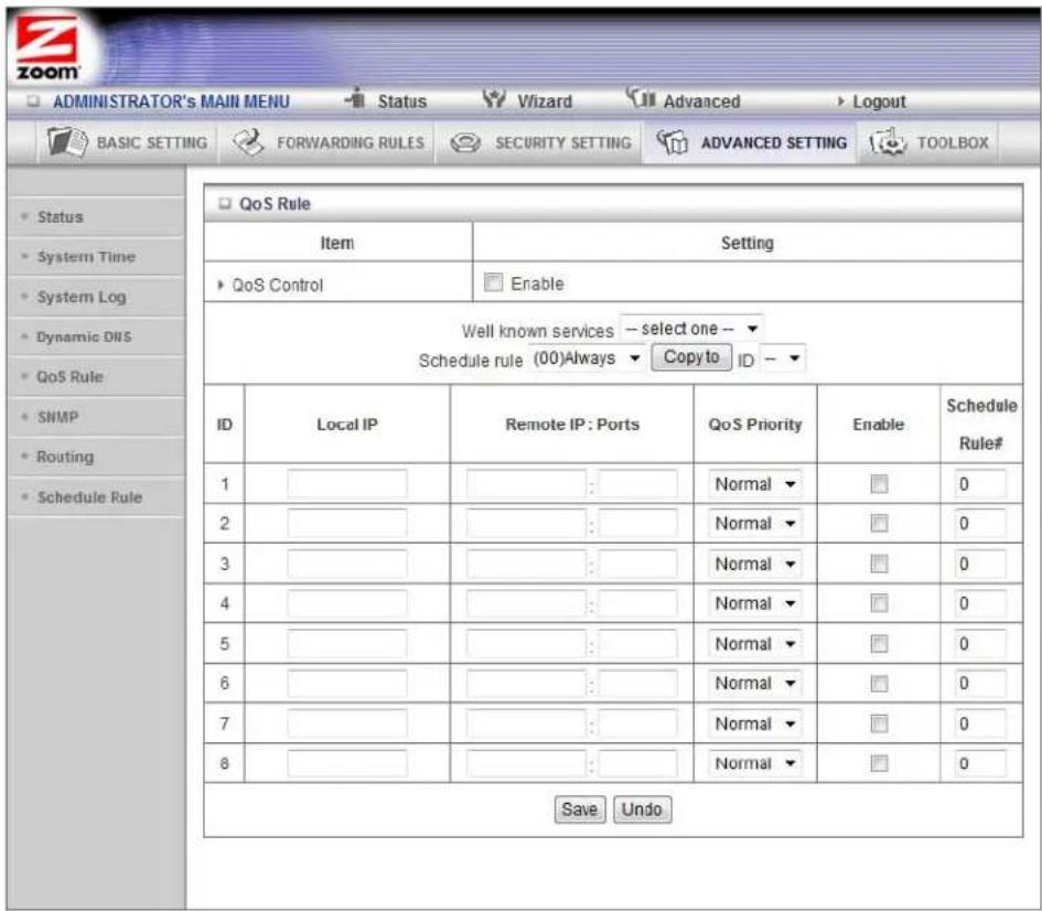
QoS Control
Click the Enable checkbox to enable QoS.
Well Known Services
If you want to give priority to one of the defined services in the Well Known Services dropdown menu select the service and the ID to copy it two and click the Copy to button.
Local IP
Define the local IP address of packets.
Remote: IP
Define the remote IP address of packets.
Remote: Ports
Define the remote port of packets.
QoS Priority
Select a value from the dropdown menu to define the priority level for the local and remote settings. Packets will be serviced based upon the priority level set. For critical applications, select High or Normal. For non-critical applications, select Low. Normal is the default value.
Enable
Click the Enable checkbox to apply the settings.
User Rule#
Select a rule from the dropdown menu to indicate when the policy applies. (0) always is the default value.
The SNMP Page
You can use the Simple Network Management Protocol (SNMP) page to set up the capability to remotely manage a computer network by polling and setting terminal values and monitoring network events. Most users do not need to set up SNMP.
![ADMINISTRATOR'S MAIN MENU Status Wizard Advanced Logout BASIC SETTING FORWARDING RULES SECURITY SETTING ADVANCED SETTING TOOLBOX SNMP Setting [HELP] Item Setting Enable SNMP Local Remote Get Community public Set Community private Allow access IP 1 Allow access IP 2 Allow access IP 3 Allow access IP 4 SNMP Version V1 V2c Save Undo](/content/2026/05/857512/images/fead347ede797cdc024d7cac158b226a38060330a97518440bff2f63b673922d.jpg)
Enable SNMP
Click the Local, Remote, or both checkboxes to enable the SNMP function. Check Local if you want the Router to respond to requests from the LAN. Check Remote if you want the Router to respond to requests from the WAN.
Get Community
Set Get Community to the GetRequest to which your device will respond.
Set Community
Set Set Community to the SetRequest that your device will accept.
IP 1, IP 2, IP 3, IP 4
Enter the IP address of your SNMP Management PCs. You must specify where the Router should send SNMP Trap messages.
SNMP Version
Select the SNMP Version that your SNMP Management software supports.
WAN Access IP Address
Enter the IP address for WAN access. The default value of 0.0.0.0 indicates that every IP address can get some information about this device, using the SNMP protocol.
The Routing Table Page
You can use the Routing Table page to enable/disable both Dynamic and Static Routing. If routing is enabled, you can specify which physical interface address to use for outgoing IP datagrams. If you have more than one Router and subnet, you will need to define a routing table that lets packets find the proper routing path and allows different subnets to communicate with each other. Most users do not need to set up Dynamic or Static Routing.
![ADMINISTRATOR'S MAIN MENU Status Wizard Advanced Logout BASIC SETTING FORWARDING RULES SECURITY SETTING ADVANCED SETTING TOOLBOX Routing Table [HELP] Item Setting Dynamic Routing Disable RIPv1 RIPv2 Static Routing Disable Enable ID Destination Subnet Mask Gateway Hop Enable 1 ______ ______ ______ ______ ______ ______ 2 ______ ______ ______ ______ ______ ______ 3 ______ ______ ______ ______ ______ ______ 4 ______ ______ ______ ______ ______ ______ 5 ______ ______ ______ ______ ______ ______ 6 ______ ______ ______ ______ ______ ______ 7 ______ ______ ______ ______ ______ ______ 8 ______ ______ ______ ______ ______ ______ Save Undo](/content/2026/05/857512/images/1d849196fba3f61c8d54ae8398f689f96ecaadd4d9c472a1ebe19a3cc3056221.jpg)
Dynamic Routing
The Routing Information Protocol (RIP) will exchange information about destinations for computing routes throughout the network. Please select RIPv2 only if you have different subnet in your network. Otherwise, please select RIPv1 if you need this protocol.
Static Routing
For static routing, you can specify up to eight routing rules. You can enter the Destination IP address, Subnet Mask, Gateway, Hop for each routing rule. Click the Enable checkbox to activate the routing table entry.
The Schedule Rule Page
You can use the Schedule Rule and Schedule Rule Setting pages to define when services will be turned on and off based on rules that you define.
1 On the Schedule Rule page, click the Enable checkbox to enable the scheduling rules, which are defined on the Schedule Rule Setting page.
![ADMINISTRATOR'S MAIN MENU BASIC SETTING FORWARDING RULES Security SETTING ADVANCED SETTING TOOLBOX Schedule Rule [HELP] Item Setting Schedule Enable Rule# Rule Name Action 1 Holiday Edit Delete 2 Weekdays Edit Delete Save Add New Rule...](/content/2026/05/857512/images/19d787bbdc88b515c6c775996023605507cba56edd9d7de1c1abadd5286b520e.jpg)
a Click Add New Rule to open the Schedule Rule Setting page.
![ADMINISTRATOR'S MAIN MENU Status Wizard Advanced Logout BASIC SETTING FORWARDING RULES SECURITY SETTING ADVANCED SETTING TOOLBOX Schedule Rule Setting [HELP] Item Setting Name of Rule 2 Weekdays System Time Tuesday, December 00, 2011 4:42:03 PM Week Day Start Time (hh:mm) End Time (hh:mm) Sunday : : : Monday : : : Tuesday 7 45 9 45 Wednesday : : : Thursday : : : Friday 2 10 6 10 Saturday : : : Every Day : : : Save Undo Back Saved! The change takes effective immediately!](/content/2026/05/857512/images/f49f5054bf3109ef7cb742fc19a0e5d1a0b653b7e66ef3b15827e5e412aa6434.jpg)
b On the Schedule Rule Setting page, specify a Rule name, a Policy that defines the Week Day and the Start Time and End Time for each rule that you are creating.
![ADMINISTRATOR'S MAIN MENU Status Wizard Advanced Logout BASIC SETTING FORWARDING RULES SECURITY SETTING ADVANCED SETTING TOOLBOX Schedule Rule Setting [HELP] Item Setting Name of Rule 2 Weekdays System Time Tuesday, December 06, 2011 4:42:03 PM Week Day Start Time (hh:mm) End Time (hh:mm) Sunday : : : Monday : : : Tuesday 7 45 9 45 Wednesday : : : Thursday : : : Friday 2 10 6 10 Saturday : : : Every Day : : : Savs Undo Back Saved! The change takes effective immediately!](/content/2026/05/857512/images/ace188af1a2df95c1a602900ee826399e4327ad20ce77df1a3c92860520243a2.jpg)
c Click Save for each rule that you create.
d Click Back to return to the Schedule Rule page.
When the Schedule Rule page opens, the rule(s) that you created and saved appear in the Rule Name column.
![ADMINISTRATOR'S MAIN MENU BASIC SETTING FORWARDING RULES SECURITY SETTING ADVANCED SETTING TOOLBOX Schedule Rule [HELP] Item Setting Schedule Enable Rule# Rule Name Action 1 Holiday Edit Delete 2 Weekdays Edit Delete Save Add New Rule...](/content/2026/05/857512/images/e662230ee536e20b47af238c34639fa12bc1a9cd0fd6cbd640a24e8a599d7235.jpg)
f Click Edit to make changes to a scheduled rule.
g Click Delete to remove a scheduled rule.
Configuring Toolbox Settings
The Toolbox Settings page lists six configuration menus on the left pane and provides a description of the configuration menus at center.
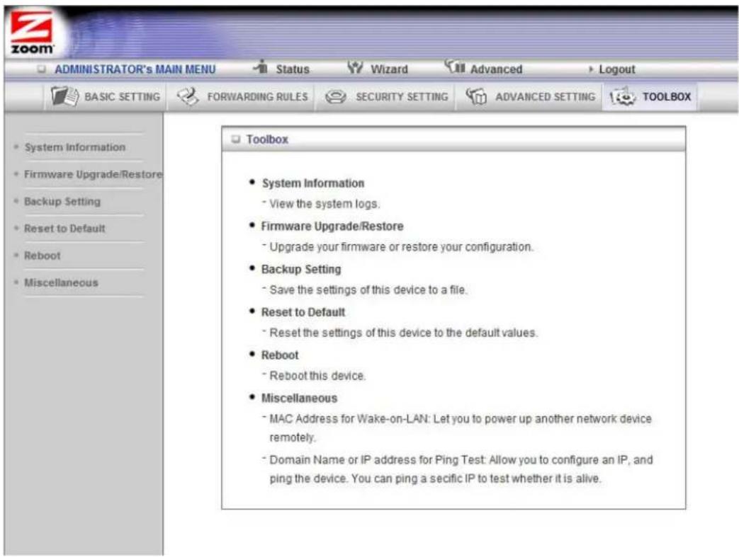
System Information Page
You can use the System Information page to view information about your Router, and to view download, and delete system logs.
The Firmware Upgrade/Restore Page
You can use the Firmware Upgrade page to update your Router to the most recent version of the Router firmware, if available or if you can restore your Router's settings if you have previously backed up your configuration using Backup Settings
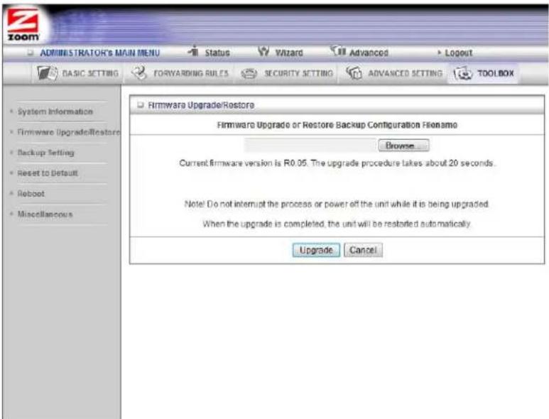
1 Click Browse to open the location where you saved the firmware update or backed up configuration file. The firmware upgrade file would have been downloaded from the Zoom web site or received via email and the backed up configuration file would have been created from using the Backup Settings page.
2 Click Upgrade.
The Backup Setting Dialog
You can back up your Router settings by clicking the Backup Setting item from the left pane of the Toolbox menu. The file config.bin is downloaded to your local computer.
The Reset to Default Dialog
You can reset the Router to its factory settings by clicking the Reset to Default item from the left pane of the Toolbox menu. The following dialog opens.
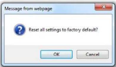
1 Click OK to reset the Router.
We recommend that you back up and save your configuration first if you've made changes and want a record of that configuration.
The Reboot Dialog
You can reboot the Router by clicking the Reboot item from the left pane of the Toolbox menu. The following dialog opens.
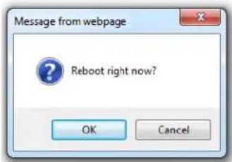
1 Click OK to reboot the Router.
The Miscellaneous Page
You can use this page to enter a MAC Address for Wake-on-LAN wake up or Ping a remote device on your network.
![ADMINISTRATOR'S MAIN MENU Status Wizard Advanced Logout BASIC SETTING FORWARDING RULES SECURITY SETTING ADVANCED SETTING TOOLBOX System Information Firmware Upgrade/Restore Backup Setting Reset to Default Reboot Miscellaneous Miscellaneous Items [HELP] Item Setting MAC Address for Wake-on-LAN Wake up Domain Name or IP address for Ping Test Ping Save Undo](/content/2026/05/857512/images/7ccd7ef9c2f9ef48353ca9fa1a211ebeda371b8bb069380041f9726240659e61.jpg)
Appendix A: Troubleshooting Tips
The following are some problems you may experience and some possible solutions to remedy the situation.
Problem
After connecting the Wireless-N 4-port Router. to a computer, the connected Ethernet (LAN) port light does not blink.
Solution
- Check that the Router's power cube is plugged into a working wall outlet and into the Router. The Router's Status light should be on and blinking.
• Make sure the PC is ON. - Make sure the Ethernet cable is plugged in properly into the PC and into the Router's Ethernet. Try replacing the Ethernet cable with another cable.
- Check that the PC's NIC (Ethernet) adapter is enabled and working properly. (Refer to your PC's documentation for details.)
Problem
I followed the instructions for connecting the Wireless-N 4-port Router hardware and entered http://192.168.2.1 in my web browser's address bar, but I cannot access the Wireless-N 4-port Router (the Status page does not appear).
Solution
- Verify that power is on to the unit and that the Ethernet cable is plugged into your Router and your computer's Ethernet (LAN) port.
- Manually reset the Wireless-N 4-port Router. Insert a paper clip into the RESET opening on the back panel, then press and hold down for 5 seconds. Then power off your computer and power it back on. After you've done that, re-enter http://192.168.2.1 in your web browser's address bar.
Note: If you still cannot access the Wireless-N 4-port Router, follow the instructions in Appendix B to check the computer's TCP/IP settings.
Problem
I am unable to connect to the Internet (and/or used the Setup Wizard to set up the Router and see the message “Connection to Internet failed”).
Solution
There are several issues that could cause this problem. Check these items:
- If you used the Setup Wizard and the connection to the Internet failed try opening a browser and going to a website. If this works then your setup is OK.
- Verify that the STATUS light on the Router is on and blinking. If it is off, check that the Router is plugged into a working wall outlet. If the light does not turn on, make sure there is power going to the outlet you are using. If the unit still doesn't work contact Zoom Technical Support. See Appendix D for contact information.
- If you are using a wireless device, try connecting a computer directly to one of the Wireless-N 4-port Router's Ethernet (LAN) ports. If a computer directly connected to the Wireless-N 4-port Router works, then the problem is with your wireless connections. See the wireless troubleshooting tip.
- If you are using the Router in Ethernet Client Mode verify that the Ethernet cable is plugged into the Router's WAN port (not its LAN port).
- If you cannot access the Internet with a computer directly connected to one of the Wireless-N 4-port Router's Ethernet (LAN) ports, check your Ethernet connection. Most computers have a power light next to the Ethernet jack to indicate the Ethernet cable is properly connected. Verify that this light is on and that the Ethernet light on the front of the Wireless-N 4-port Router is on. If the Ethernet light is off on either the Wireless-N 4-port Router or on the computer, verify that the cable is properly pushed in. If the light still doesn't turn on, you should try another Ethernet cable.
- Try turning your computer off and then on. This ensures that your computer gets a correct IP address from the Wireless-N 4-port Router.
Problem
My computer/devices are not connecting wirelessly to the Wireless-N 4-port Router.
Solution
Try the following:
- Verify that a "wired" computer can access the Internet.
If it cannot, try the steps outlined in the previous troubleshooting tip.
If the wired computer can access the Internet, reboot the devices(s) on your wireless network (this will allow for the computers to release and renew their IP addresses) and try to access the Internet again.
If you still cannot connect to the Internet wirelessly, continue below.
You should also verify that Zoom (or whatever you changed the SSID/network name to) is selected as the wireless network. If it is not, then you are connected to the wrong network. To verify the network, follow the instructions in Chapter 6, Connecting Wireless Devices to the Wireless-N 4-port Router.
- Check your wireless security settings on your Wireless-N 4-port Router and verify that your device is using the same settings.
- Check the signal strength of your wireless connection. Most wireless adapters have some type of signal strength meter that shows how strong your wireless signal is. Windows users, click the Wireless icon in your system tray to check signal strength. If your signal strength is not strong enough, try the following:
➢ Reorient the receiving antenna on your Wireless-N 4-port Router.
➢ Move the Wireless-N 4-port Router to another area.
➢ Move the device trying to access the Wireless-N 4-port Router to a different location, ideally closer to the Wireless-N 4-port Router.
- Change the wireless channel. In the unlikely event that you experience performance issues with your wireless network, you may want to set your network up on a channel that's different from the factory-set channel of 10. To do that, follow these steps:
1 In the Web browser address bar, type the Router's default IP address, http://192.168.2.1 and then click Enter.
2 In the System Password field, type admin and then click Login.
3 When the ADMINISTRATOR'S Main Menu opens, click Advanced on the Toolbar.
4 On the Basic Settings page, click Wireless on the left-side menu to open the Wireless page.
5 On the Wireless page, from the Channel drop-down menu, select a channel number for your network that is not being used by another network. If possible, try to maintain a 5-channel difference between your network and other nearby networks. You may want to try, for example, channel 1 or 6.
6 nBethareltandick/Slave/Application matching cha
wirelessly to the Wireless-N 4-port Router will automatically switch to the new channel.
- If you are using a computer with a wireless network card installed, access the network card's software and verify that it is connected to the Zoom network (or whatever you changed the SSID/network name to) and that the signal strength is adequate. Refer to the documentation that came with the network card if you need help doing this.
- Refer to the documentation provided with your network device or contact its manufacturer for assistance.
Appendix B: TCP/IP Network Settings
If you are using a Mac computer, you must ensure that your computer's TCP/IP network settings are configured properly. Otherwise, you will not be able to connect to the Internet.
Note: If you are using a Windows computer, you do not have to configure the TCP/IP settings if you are using DHCP because your Windows computer will automatically configure them for you. If you are not using DHCP, you will need to set up the TCP/IP settings for your Windows computer. Windows users who are troubleshooting the Wireless-N 4-port Router will need to verify the TCP/IP settings.
Depending on your operating system, follow the steps in the appropriate section to ensure your TCP/IP settings are correct.
Macintosh TCP/IP Settings
How you configure your Macintosh computer's network settings differs, depending on your Mac OS. Follow the steps in the appropriate section to ensure your TCP/IP settings are correct.
Mac OS X 10.7 (Lion), 10.6 (Snow Leopard), and 10.5 (Leopard)
1 From the Dock or Apple menu, select System Preferences and then Network.
2 Select your connection method, normally Ethernet for a wired connection.
3 On the right pane, select Using DHCP from the Configure IPv4 (for Mac OS X v10.7 and v10.6) and Configure (for Mac OS X v10.5) drop-down mcnu. All of the text fields should be left blank.
4 Click Apply.
Mac OS X 10.4 and 10.3
1 From the Dock or Apple menu, select System Preferences and then Network.
2 Select your connection method, normally Built-in Ethernet for a wired connection.
3 Make sure the TCP/IP tab is selected, and then select Using DHCP from the Configure IPv4 drop-down menu. All of the text fields should be left blank.
4 Click Apply Now.
Mac OS 7.6.1 - 9.2.2
1 From the Apple menu, choose Control Panels and then TCP/IP to display the TCP/IP Window.
2 Under Connect via, select Ethernet built-in.
3 Under Configure, select Using DHCP Server. Do not enter anything in the DHCP Client ID field.
4 Close the TCP/IP Window. You will be asked if you want to save the changes. Click Save.
Windows TCP/IP Settings
How you configure your Windows computer's network settings differs, depending on your operating system.
Windows 7 Users:
1 From the desktop, click the Start button, select Control Panel.
2 Under Network and Sharing Center, select Change adapter settings from the menu on the left side of the screen.
3 Right-click on the Local Area Connection icon and select Properties.
4 In the Local Area Connection Properties dialog box, highlight Internet Protocol Version 4 (TCP/IPv4) and click the Properties button.
- If you are using DHCP (most users): Ensure that Obtain an IP address automatically is selected and that either Obtain a DNS server address automatically or Enable DNS is selected. All fields should be blank.
- If you are using a static IP address: Ensure that Use the following IP address and Use the following DNS server addresses are selected, and that the correct IP address, Subnet mask, Default gateway, and Preferred DNS server values appear.
5 Click OK twice.
6 Re-enter 192.168.2.1 in your Web browser's address bar.
Windows Vista Users:
1 From the desktop, click the Start button, select Control Panel, and then double-click Network and Sharing Center.
2 In the Network and Sharing Center window, under Tasks, select Manage Network Connections.
3 In the Network Connections window, double-click the Local Area Connection option.
4 In the Local Area Connection Status dialog box, click the Properties button.
5 In the Local Area Connection Properties dialog box, highlight Internet Protocol Version 4 (TCP/IPv4) and click the Properties button.
- If you are using DHCP (most users): Ensure that Obtain an IP address automatically is selected and that either Obtain a DNS server address automatically or Enable DNS is selected. All fields should be blank.
- If you are using a static IP address: Ensure that Use the following IP address and Use the following DNS server addresses are selected, and that the correct IP address, Subnet mask, Default gateway, and Preferred DNS server values appear.
6 Click OK, then click Close.
7 Re-enter 192.168.2.1 in your Web browser's address bar.
Windows XP
1 Open the Internet Protocol (TCP/IP) Properties dialog box.
a From the desktop, click the Start button, point to Control Panel, and then click Network and Internet Connections.
b Click Network Connections.
c Right-click the Local Area Connection icon, and select Properties.
d Select your NIC card's TCP/IP entry (it should include "TCP/IP" in it, but not "AOL," "Dial-up," or "Adapter") and click the Properties button.
2 Ensure the following is selected, depending on whether you are using dynamic (DHCP) or static IP addressing:
- If you are using DHCP (most users): Ensure that Obtain an IP address automatically is selected and that either Obtain a DNS server address automatically or Enable DNS is selected. All fields should be blank.
- If you are using a static IP address: Ensure that Use the following IP address and Use the following DNS server addresses are selected, and that the correct IP address, Subnet mask, Default gateway, and Preferred DNS server values appear.
Windows 2000
1 Open the Internet Protocol (TCP/IP) Properties dialog box.
a From the desktop, click the Start button, point to Settings, then Network and Dial-up Connections.
b Right-click the Local Area Connection icon, and select Properties.
c Select your NIC card's TCP/IP entry (it should include "TCP/IP" in it, but not "AOL," "Dial-up," or "Adapter") and click the Properties button.
2 Ensure the following is selected, depending on whether you are using dynamic (DHCP) or static IP addressing:
- If you are using DHCP (most users): Ensure that Obtain an IP address automatically is selected and that either Obtain a DNS server address automatically or Enable DNS is selected. All fields should be blank.
- If you are using a static IP address: Ensure that Use the following IP address and Use the following DNS server addresses are selected, and that the correct IP address, Subnet mask, Default gateway, and Preferred DNS server values appear.
Windows 98/Me
1 Open the Internet Protocol (TCP/IP) Properties dialog box.
a From the desktop, click the Start button, point to Settings, then Control Panel.
b Double-click the Network icon to display the Network dialog box.
c Select your NIC card's TCP/IP entry (it should include "TCP/IP" in it, but not "AOL," "Dial-up," or "Adapter") and click the Properties button and then click OK
2 Ensure the following is selected, depending on whether you are using dynamic (DHCP) or static IP addressing:
If you are using DHCP (most users): Ensure that Obtain an IP address automatically is selected and that either Obtain a DNS server address automatically or Enable DNS is selected. All fields should be blank.
If you are using a static IP address: Ensure that Use the following IP address and Use the following DNS server addresses are selected, and that the correct IP address, Subnet mask, Default gateway, and Preferred DNS server values appear. On the DNS Configuration tab, ensure that Enable DNS is selected and that something appears in the Host box. (If not, enter any name, word, or combination of letters and numbers.) Ensure that the DNS Server Search Order box contains 192.168.2.1
If your TCP/IP settings are correct and you still cannot access your computer try rebooting you computer. If that does not work try replacing the Ethernet cable.
Appendix C: Setting up Your Network Using WPS
If all the wireless devices you plan to connect to your network support Wi-Fi Protected Setup (WPS), you can use WPS to connect and secure your devices in one step. To use WPS follow the instructions below.
Note: WPS configures one client device at a time. Please repeat the configuration method for each client on your wireless network that supports WPS security.
Configuration Methods
WPS offers three configuration methods. Choose the method that is compatible with the hardware and software options available on your “client device,” which is the device you’re connecting wirelessly to the Wireless-N 4-port Router.
Method One
Use this method if your client device has a WPS button. This button can be either a physical button on the unit or a software button in its application.
1 Press the WPS button on your Wireless-N 4-port Router and hold it in for three (3) seconds. The Wireless light starts blinking rapidly. (Note: Wireless must be disabled for the WPS button to work. To turn on wireless using the button on the Router, press the Wireless button on the Router and hold it for 5 seconds. Then press the same button which is also the WPS button as stated above.)
Important! The Registrar (the device configuring the WLAN) goes into the WPS mode and the Enrollee (the device joining the WLAN) then looks for it. You should always start the Registrar first. By default your Wireless-N 4-port Router is configured as a Registrar.
2 Click or press the WPS button on the client device.
Important! You must do this within two minutes after placing he Router into WPS discovery mode.
3 Refer to your client device's documentation for further instructions, if necessary.
Method Two
Use this method if your client device already has a WPS PIN number. The client is the Enrollee.
1 If you haven't already done so, open a Web browser and type http://192.168.2.1 in the address bar.
a When the Configuration Manager launches, log in as admin, then select Advanced > Basic Settings > Wireless to open the Wireless Setup page.
b Click the WPS Setup button to open the Wi-Fi Protected Setup page.
c Select Enrollee PIN from the Setup option.
d Enter the PIN number from your client device.
e Click Trigger to start the connection process on the Router. Important! You must do this within two minutes after placing the Router into WPS discovery mode.
f On the Wireless-N 4-port Router, when the program displays a message that the process succeeded, click Save to save the configuration.
Method Three
Use this method if your client device requests the Router's PIN number. The client is the Registrar. Use this method if the client(s) are to connect to multiple access points so that a client will control the configuration instead of the Router.
1 If you haven't already done so, open a Web browser and type http://192.168.2.1 in the address bar.
a When the Configuration Manager launches, log in as admin, then select Advanced > Basic Settings > Wireless to open the Wireless Setup page.
b Click the WPS Setup button.
c Select Enrollee from the Setup option.
d Click Generate New PIN to generate a new PIN number.
e Enter the Router's PIN Number into your client device. Refer to your client's documentation for further details.
Important! You must do this within two minutes after starting the Router.
Click Save to save the configuration.
Appendix D: Registering Your Product and Getting Help
Zoom supports this Router. If you need assistance, please contact Zoom directly. We encourage you to register your product and to notice the many support options available from Zoom. Please go to www.zoomtel.com and select Technical Support. From here you can register your new Router, contact our technical support experts, use our SmartFacts™ intelligent database, and get warranty information.
If you need to contact Zoom Customer Support, you can call us by dialing:
U.S.: (617) 753-0965
U.K. London: +44 2033180660
Manchester: +44 1618840074
Appendix E: Regulatory Information

Declaration of Conformity
The manufacturer declares under sole responsibility that this equipment is compliant to Directive 1999/5/EC via the following. This product is CE marked.
Director, Hardware Engineering/
Regulatory Notices for Wireless-N 4-port Router
U.S. FCC Part 15 Emissions Statement
This equipment has been tested and found to comply with the limits for a Class B digital device, pursuant to part 15 of the FCC Rules. These limits are designed to provide reasonable protection against harmful interference in a residential installation. This equipment generates, uses and can radiate radio frequency and, if not installed and used in accordance with the instructions, may cause harmful interference to radio communications.
However, there is no guarantee that interference will not occur in a particular installation. If this equipment does cause harmful interference to radio or television reception, which can be determined by turning the equipment off and on, the user is encouraged to try to correct the interference by one or more of the following measures:
• Reorient or relocate the receiving antenna.
- Increase the separation between the equipment and receiver.
- Connect the equipment into an outlet on a circuit different from that to which the receiver is connected.
- Consult the dealer or an experienced radio/TV technician for help.
TCC. Caution: Any changes or modifications not expressly approved by the party responsible for compliance could void the user's authority to operate this equipment.
Operations in the 5.15-5.25GHz band are restricted to indoor usage only.
This device complicity with Part 15 of the FCC Rules. Operation is subject to the following two conditions: (1) This device may not cause harmful interference, and (2) this device must accept any interference received, including interference that may cause undesired operation.
IMPORTANT NOTE:
Radiation Exposure Statement:
This equipment complices with FCC radiation exposure limits set forth for an uncontrolled environment. This equipment should be installed and operated with minimum distance 20cm between the radiator & your body.
This transmitter must not be co-located or operating in conjunction with any other antenna or transmitter.
Note: The country code selection is for non-US model only and is not available to all US model. Per FCC regulation, all WiFi product marketed in US must fixed to US operation channels only.
European Declaration of Conformity
The manufacturer declares under sole responsibility that this equipment is compliant to Directive 1999/5/T.C (R&TIT. Directive) via the following. This product is CE Marked.
| Directive | Standard | Test | Report |
| 73/23/EEC-Low Voltage | EN60950-1:2006 + A11:2009, IT.C60950-1:2005 | Electrical safety | |
| 89/336/EEC-EMC EN | 301 489-1 v1.6.1 :2005-09; EN 301 489-17 1.2.1 :2002; EN 55022 : 2006, Class B | EMC-immunity EMC-emissions |
Electrostatic Discharge Statement
The unit may require resetting after a severe electrostatic discharge event.
Note: If you do not use the supplied phone cord, use an equivalent of minimum AWG 26 line cord.
CAUTION: To reduce the risk of fire, use only No. 26 AWG or larger UL Listed or CSA Certified Telecommunication Line Cord
Europe - EU Declaration of Conformity
This device complies with the essential requirements of the R&TTE Directive 1999/5/E.C. The following test methods have been applied in order to prove presumption of conformity with the essential requirements of the R&TTE Directive 1999/5/EC:
- TN 60950-1:2006
Safety of Information Technology Equipment
- EN50385 : 2002
Assessment of electronic and electrical equipment related to human exposure restrictions for electromagnetic fields
- TN 300 328 V1.7.1: (2006-10)
Electromagnetic compatibility and Radio spectrum Matters (ERM); Wideband Transmission systems; Data transmission equipment operating in the 2,4 GHz ISM band and using spread spectrum modulation techniques; Harmonized EN covering essential requirements under article 3.2 of the R&TIT. Directive
EN 301 489-1 V1.8.1: (2008-04)
Electromagnetic compatibility and Radio Spectrum Matters (ERM); ElectroMagnetic Compatibility (EMC) standard for radio equipment and services; Part 1: Common technical requirements
EN 301 489-17 V1.3.2 (2008-04)
Electromagnetic compatibility and Radio spectrum Matters (ERM); ElectroMagnetic Compatibility (EMC) standard for radio equipment and services; Part 17: Specific conditions for 2,4 GHz wideband transmission systems and 5 GHz high performance RLAN equipment
This device is a 2.4 GHz wideband transmission system (transceiver), intended for use in all EU member states and EFTA countries, except in France and Italy where restrictive use applies.
In Italy the end-user should apply for a license at the national spectrum authorities in order to obtain authorization to use the device for setting up outdoor radio links and/or for supplying public access to telecommunications and/or network services.
This device may not be used for setting up outdoor radio links in France and in some areas the RF output power may be limited to 10 mW EIRP in the frequency range of 2454 – 2483.5 MHz. For detailed information the end-user should contact the national spectrum authority in France.
CE0984
| Česky [Czech] | Zoom Telephonics, Inc. tímto prohlašuje, že tento Zoom Wireless-N 4-port Router je ve shodě se základními požadavky a dalšími příslušnými ustanoveními směrnice 1999/5/ES. |
| Dansk [Danish] | Undertegnede Zoom Telephonics, Inc. erklarer herved, at folgende udstyr Zoom Wireless-N 4-port Router overholder de væsentlige krav og øvrige relevante krav i direktiv 1999/5/EF. |
| Deutsch [German] | Iiermit erklärt Zoom Telephonics, Inc., dass sich das Gerät Zoom Wireless-N 4-port Router in Übereinstimmung mit den grundlegenden Anforderungen und den übrigen einschlägigen Bestimmungen der Richtlinie 1999/5/EG befindet. |
| Eesti [Estonian] | Käcsolevaga kinnitab Zoom Telephonics, Inc. scadme Zoom Wireless-N 4-port Router vastavust direktüvi 1999/5/EÜ põhinõuetele ja nimetatud direktüvist tulenevatele teistele asjakohastele sätetele. |
| English | Hereby, Zoom Telephonics, Inc., declares that this Zoom Wireless-N 4-port Router is in compliance with the essential requirements and other relevant provisions of Directive 1999/5/EC. |
| Español [Spanish] | Por medio de la presente Zoom Telephonics, Inc. declara que el Zoom Wireless-N 4-port Router cumple con los requisitos esenciales y cualesquiera otras disposiciones aplicables o exigibles de la Directiva 1999/5/CF. |
| Ελληρική [Greek] | ME THN ΠΑΡΟΥΣΑ Zoom Telephonics, Inc. ΔΗΛΩΝΕΙ OTI Zoom Wireless-N 4-port Router ΣΥΜΜΟΡΦΩΝΕΤΑΙ ΠΡΟΣ ΤΙΣ ΟΥΣΙΩΔΕΙΣ ΑΠΑΓΙΤΙΣΕΙΣ ΚΑΙ ΤΙΣ ΛΟΙΠΕΣ ΣΧΕΤΙΤΚΕΣ ΔΙΑΤΑΞΕΙΣ ΤΙΣ ΟΔΙΠΓΙΑΣ 1999/5/ΕΚ. |
| Français [French] | Par la présente Zoom Telephonics, Inc. déclare que l'appareil Zoom Wireless-N 4-port Router est conforme aux exigences essentielles et aux autres dispositions pertinentes de la directive 1999/5/CF. |
| Italiano [Italian] | Con la presente Zoom Telephonics, Inc. dichiara che questo Zoom Wireless-N 4-port Router è conforme ai requisiti essenziali ed alle altre disposizioni pertinenti stabilite dalla diretriva 1999/5/CF. |
| Latviski [Latvian] | Ar šo Zoom Telephonics, Inc. deklarė, ka Zoom Wireless-N 4-port Router atbilst Direktīvas 1999/5/EK būtiskajām prasībām un citiem ar to saistītajiem noteikumiem. |
| Lietuvių | Šiuo Zoom Telephonics, Inc. deklaruoja, kad šis Zoom Wireless-N 4-port Router atitinka esminius |
| [Lithuanian] reikalavimus ir kitas 1999/5/FB Direktyvos nuostatas. | |
| NL Nederlands [Dutch] | Hierbij verklaart Zoom Telephonics, Inc. dat het toestel Zoom Wireless-N 4-port Router in overeenstemming is met de essentiële cisen en de andere relevante bepalingen van richtlijn 1999/5/F.G. |
| NT Malti [Maltese] | Hawnbckk, Zoom Wireless-N 4-port Router, jiddikjara li dan Zoom Telephonics, Inc. jikkonforma mal-htigijiet essenzjali u ma provvedimenti ohrajn relevanti li hemm fid Dirrettiva 1999/5/EC. |
| HU Magyar [Hungarian] | Alulírott, Zoom Telephonics, Inc. nyilatkozom, hogy a Zoom Wireless-N 4-port Router megfelel a vonatkozó alapvető követelményeknek és az 1999/5/EC irányelv egyéb előírásainak. |
| PL Polski [Polish] | Niniejszym Zoom Telephonics, Inc. oświadcza, že Zoom Wireless-N 4-port Router jest zgodny z zasadniczymi wymogami oraz pozostałymi stosownymi postanowieniami Dyrektywy 1999/5/EC. |
| PT portuguès [portugusc] | Zoom Telephonics, Inc. declara que este Zoom Wireless-N 4-port Router está conforme com os requisitos essenciais e outras disposições da Directiva 1999/5/CE. |
| d Slovensko [Slovenian] | Zoom Telephonics, Inc. izjavlja, da je ta Zoom Wireless-N 4-port Router v skladu z bistvenimi zahtevami in ostalimi relevantnimi določili direktive 1999/5/ES. |
| Slovensky [Slovak] | Zoom Telephonics, Inc. týmto vyhlasuje, že Zoom Wireless-N 4-port Router splňa základné požiadavky a všctky príslušné ustanovenia Smernicc 1999/5/F.S. |
| Suomi [Finnish] | Zoom Telephonics, Inc. vakuuttaa täten cttä Zoom Wireless-N 4-port Router tyyppinen laite on direktiivin 1999/5/TY olecellisten vaatimusten ja sitä koskevien direktiivin muiden ehtojen mukainen. |
| Sw Slovakia [Swedish] | Härmed intygar Zoom Telephonics, Inc. att denna Zoom Wireless-N 4-port Router står I överensstämmelse med de väsentliga egenskapskrav och övriga relevanta bestämmelser som framgår av direktiv 1999/5/EG. |
Compliance Model Identification
| Model name Product name | ||
| FCC 15C, FCC 15B, FCC 68 | Zoom Wireless-N 4-port Router SERIES | ES 1095 MODEL 4403 |
| IC , ICES-003, CS-03 | Zoom Wireless-N 4-port Router Series | 1095 Model 4403 |
| CT0678 ! | Zoom Wireless-N 4-port Router Series | 1095 |
| FCC Part 68 ID BDNDL01B | 1093 | |
| FCC ID BDN1093WL | ||
| IC ID 1535A-1093 | ||
Limited Warranty
Zoom Telephonics, Inc. (hereinafter “Zoom”) warrants this product against defects in material and workmanship for a warranty period of one year. The one year warranty may be extended only by Zoom as required by local law in the country where this product is sold by Zoom. This warranty applies to the original end-user purchaser.
For all Zoom products other than software, Zoom will, solely at its option, repair or replace this product with a functionally equivalent new or factory-reconditioned product during the warranty period. The consumer will deliver the product to Zoom. All transportation risks and costs in connection with this warranty service are the responsibility of the consumer.
Zoom will replace software at no charge if there is a defect in materials or workmanship for a period of 30 days from date of original retail purchase, provided the defective software is returned to Zoom. Shipments from Zoom will normally be via U.S. Mail. Software products supplied by Zoom are sold “as is,” without warranty, either expressed or implied, as to function, application, merchantability, performance, and quality.
Zoom is not responsible for incidental or consequential damages, and is not responsible for damages resulting from the breach of any expressed or implied warranty. Zoom is not responsible for any costs of recovering, reprogramming, or reproducing any programs or data stored or used with the Zoom products, damage to property, and to the extent permitted by law, damages for personal injury.
This warranty is in lieu of all other warranties, expressed or implied. We do not assume or authorize assumption for us of any other warranty expressed or implied. Some states and countries do not allow the exclusion or limitation of incidental or consequential damages, so the above limitation or exclusions may not apply to you.
This warranty does not apply if the Zoom product has been damaged by accident, abuse, lightning or other natural disasters, misuse or misapplication, or if it has been modified without the written permission of Zoom, or if any serial number has been removed or defaced.
This warranty shall not be applicable to the extent that any provisions of this warranty are prohibited by any federal, state, or municipal law that cannot be preempted. This warranty gives you specific legal rights, and you may also have other rights that vary from state to state or country to country.


- Contents
- Contents 3
- Getting Started....5
- Using the Router Mode....6
- Ethernet Client Mode 22
- Setting up the Wireless-N 4-port Router as a Repeater.... 30
- Setting up a Network 34
- Connecting Wireless Devices to the Wireless-N 4-port Router....36
- Using the Configuration Manager's Advanced Program 42
- Getting Started
- Package Contents
- Introduction
- 2
- Using the Router Mode
- Installing the Hardware
- Using the Setup Wizard
- Step 1. Setup Login Password
- Step 2. WAN Setup
- Selecting the WAN Type
- Manually Selecting your WAN Type
- Configuring the Dynamic IP Address
- Configuring PPPoE
- Configuring the Static IP Address
- Configuring PPTP
- Configuring L2TP
- Step 3. Wireless Settings
- Wireless Security Settings
- Step 4. Summary
- Step 5. Finish
- 3
- Ethernet Client Mode
- Configuring the Router by Using a Computer
- Step 2. WAN Type Setup
- Step 3. Ethernet Client Mode page
- Step 5. Completing the Installation
- Setting up the Wireless-N 4-port Router as a Repeater
- Setting up a WDS network
- Deciding which WDS Mode to Use
- Setting Up the Router in Hybrid mode or WDS Only mode
- Setting up a Network
- To Connect Additional Wired Computers
- To Connect a Network Device
- Connecting Wireless Devices to the Wireless-N 4-port Router
- Establishing your Wireless Network
- Connecting a Windows 7 Computer with Built-in Wireless Capabilities
- To disconnect from the current network:
- Connecting a Windows Vista Computer with Built-in Wireless Capabilities
- Connecting a Windows XP Computer with Built-in Wireless Capabilities
- Connecting a Wireless-enabled Computer or Device (including the iPhone® or other cellular phones, the iPod Touch®, etc.) to the Wireless-N 4-port Router
- Tip!
- Connecting a Computer with a Wireless Adapter to the Wireless-N 4-port Router
- Using the Configuration Manager's Advanced Program
- Changing Default Settings
- Online Help
- Launching the Configuration Manager's Advanced Program
- Configuring Basic Settings
- The Basic Setup Page
- WAN Type
- Host Name (optional)
- Enable MAC Cloning (optional)
- Connection Control
- MTU (Maximum Transmission Unit)
- NAT
- IGMP Proxy
- The LAN Setup Page
- LAN IP Address
- Subnet Mask
- DHCP Server
- Lease Time
- IP Pool Starting Address
- IP Pool Ending Address
- Domain Name (optional)
- Primary DNS
- Secondary DNS
- Primary WINS (optional)
- Secondary WINS (optional)
- Gateway
- Fixed Mapping
- The Wireless Settings Page
- Wireless
- SSID (Wireless Network Name)
- Wireless Mode
- Bandwidth
- Broadcast Wireless Network Name
- Wireless Schedule Rule
- Channel
- WDS
- WPS
- Security
- The Change Password Page
- Configuring Forwarding Rules
- The Virtual Server Page
- Server IP
- Service Port
- Private Port
- Protocol
- Enable
- Schedule Rule#
- The Port Triggering Page
- Trigger
- Incoming Ports
- The Miscellaneous Page
- IP Address of DMZ Host
- Super DMZ (IP Passthrough)
- UPnP setting
- Xbox® Support
- Configuring Security Settings
- Packet Filters Page
- Filtering Policies
- Filtering Rules
- Source IP address
- The Domain Filters Page
- Domain Filter
- Log DNS Query
- Privilege IP Address Range
- Domain Suffix
- Action
- Schedule Rule #
- The URL Blocking Page
- URL Blocking Enable
- URL Blocking Setting
- URL
- The MAC Address Control Page
- MAC Address Control
- Association control
- DHCP clients
- MAC Address
- IP Address
- Configuring Advanced Settings
- The System Time Page
- To Set the Date and Time using NTP protocol
- To Set the Date and Time using the Local Computer
- The System Log Page
- IP Address for Syslogging
- E-mail alert settings
- SMTP Server IP and Port
- SMTP Username and Password
- E-mail addresses
- E-mail Subject
- The Dynamic DNS Page
- The QoS Rule Page
- QoS Control
- Well Known Services
- Local IP
- Remote: IP
- Remote: Ports
- QoS Priority
- User Rule#
- The SNMP Page
- Enable SNMP
- Get Community
- Set Community
- IP 1, IP 2, IP 3, IP 4
- SNMP Version
- WAN Access IP Address
- The Routing Table Page
- Dynamic Routing
- Static Routing
- The Schedule Rule Page
- Configuring Toolbox Settings
- System Information Page
- The Firmware Upgrade/Restore Page
- The Backup Setting Dialog
- The Reset to Default Dialog
- The Reboot Dialog
- Appendix A: Troubleshooting Tips
- Problem
- Solution
- Appendix B: TCP/IP Network Settings
- Macintosh TCP/IP Settings
- Mac OS X 10.7 (Lion), 10.6 (Snow Leopard), and 10.5 (Leopard)
- Mac OS X 10.4 and 10.3
- Mac OS 7.6.1 - 9.2.2
- Windows TCP/IP Settings
- Windows 7 Users:
- Windows Vista Users:
- Windows XP
- Windows 2000
- Windows 98/Me
- Appendix C: Setting up Your Network Using WPS
- Configuration Methods
- Method One
- Method Two
- Method Three
- Appendix D: Registering Your Product and Getting Help
- Appendix E: Regulatory Information
- Declaration of Conformity
- Regulatory Notices for Wireless-N 4-port Router
- U.S. FCC Part 15 Emissions Statement
- IMPORTANT NOTE:
- Radiation Exposure Statement:
- European Declaration of Conformity
- Europe - EU Declaration of Conformity
- CE0984
- Limited Warranty
Brand : ZOOM
Model : 4403
Category : Router