
ET-PKD521B - Uncategorized PANASONIC - Free user manual and instructions
Find the device manual for free ET-PKD521B PANASONIC in PDF.

| Product Type | Projector Mount Bracket |
| Model Number | ET-PKD521B |
| Brand | Panasonic |
| Dimensions (W x H x D) | 350 mm x 52.5 mm x 535 mm (13-25/32" x 2-1/16" x 21-1/16") |
| Weight | Approx. 4.1 kg (9.04 lbs) |
| Compatible Ceiling Mount Brackets | ET-PKD520H (High Ceilings), ET-PKD520S (Low Ceilings) |
| Supported Projectors | PT-RQ25K, PT-RQ18K, PT-RZ24K, PT-RZ17K, PT-RZ14K, PT-RQ22K, PT-RZ21K, PT-RS20K, PT-RZ16K, PT-RQ13K, PT-RZ12K, PT-RS11K |
| Supplied Parts | Projector mount bracket (1), Hex head bolt with captive washer M6 x 16 (6), Hex head bolt with captive washer M10 x 40 (4), Wire rope approx. 2.0 mm x 800 mm (4) |
| Tightening Torque (M6 bolts) | 4 ± 0.5 N·m |
| Tightening Torque (M10 bolts) | 20 ± 1 N·m |
| Installation Requirement | Must be performed by certified personnel |
| Safety Features | Drop-prevention wire ropes, horizontal tilt adjustment |
| Material | High-strength metal (assumed) |
| Color | Black (typical for such brackets) |
| Warranty | Standard Panasonic warranty (refer to product documentation) |
Frequently Asked Questions - ET-PKD521B PANASONIC
User questions about ET-PKD521B PANASONIC
0 question about this device. Answer the ones you know or ask your own.
Ask a new question about this device
Download the instructions for your Uncategorized in PDF format for free! Find your manual ET-PKD521B - PANASONIC and take your electronic device back in hand. On this page are published all the documents necessary for the use of your device. ET-PKD521B by PANASONIC.
USER MANUAL ET-PKD521B PANASONIC
Installation Instructions
Projector Mount Bracket
Model No. ET-PKD521B
natural_image
Technical line drawing of a mechanical assembly with a cylindrical component inserted into a housing (no text or symbols visible)ENGLISH
FRANÇAIS
DEUTSCH
日本語
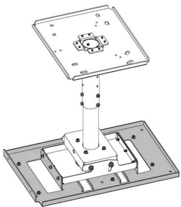
* The figure above shows this product combined with the separately sold ET-PKD520H Ceiling Mount Bracket (for High Ceilings).
Thank you for purchasing this Panasonic product.
■ To customers
The "Installation Instructions" is intended for use by installation personnel. Be sure to employ certified personnel to perform the installation.
After installation, have the installation personnel return these "Installation Instructions" to you, and save it for future use. When moving or removing the projector, give this manual to the certified personnel and have them perform the procedure.
■ To installation personnel
Read the "Installation Instructions" thoroughly and then perform the operation correctly and safely. Be sure to read through the section entitled "Read this first!" (page 3) before proceeding with the installation. After installation, return these "Installation Instructions" to the customer.

Contents
Read this first! 3
Product components....4
Standard installation dimensions....5
Installation....21
Setting up the screen....21
Screws tightening torques 21
Installing the bracket to the projector....21
Attaching the wire rope to the projector....22
Specifications 23
WARNING:
Installation work should only be carried out by the certified personnel.
- If this product is not installed correctly, serious accidents may result.
- Follow the instructions specified in "Installation" of this manual, and perform secure installation.
Install the ceiling mount bracket in accordance with the structure and materials of the installation location.
- If a mistake is made in the installation procedure, the ceiling mount bracket may fall down and an injury may result.
Mounting must be carried out by two or more persons.
- When installing the projector in an overhead location, for example, in a high ceiling, at least two persons will be required to handle the installation.
Make sure that your footing is safe and secure during installation.
- If your footing is not secure, you may trip or fall down, and an injury may result.
Do not loosen or remove the unit screws and bolts unnecessarily.
● The projector may fall down and an injury may result.
Do not install in a location that is not strong enough.
- If the installation location is not strong enough, the unit may fall down and damage to the projector or an injury may result.
Do not install the ceiling mount bracket in humid or dusty locations or in locations where the ceiling mount bracket may be exposed to oily smoke, steam, or excessive heat.
- Failure to obey may result in fire or electric shock. In addition, oil will cause the plastic to deteriorate, which may result in a drop hazard.
Do not allow children to reach the supplied screws and metal fittings.
● These items can cause personal injury if swallowed.
- If swallowed, seek medical help immediately.
Do not disassemble or modify the projector mount bracket.
● The projector may be damaged or fall down, and an injury may result.
CAUTION:
Install only the designated projector.
Install only using the designated method.
● Failure to obey may result in dropping, damage to the projector, or injury.
Do not install the ceiling mount bracket in a place which may impede projector ventilation.
- If this is not observed, fire may result.
Do not hang from or hang objects on the projector or ceiling mount bracket.
● The projector may fall and cause injury.
Use only the specified ceiling mount bracket (for high ceilings or for low ceilings).
● Failure to obey may result in dropping, damage to the projector, or injury.
Always use the supplied parts when performing installation.
- Otherwise, this may cause damaged projector to fall and cause injury.
Install the mounting screws and power cable in such a way that they will not make contact with the inside metals of the ceiling.
● Electric shocks may result from contact with any metal objects inside the ceiling.
■ Panasonic Connect Co., Ltd. disclaims all liability for any accidents or any damage caused by the installation of the ceiling mount bracket using methods that are not described in these Installation Instructions or methods that do not use the parts specified in these Instructions.
■ If products are no longer being used, they should be dismantled and removed by the certified personnel as soon as possible.
Product components
This is a projector mount bracket for installing projectors.
Use this together with the ceiling mount bracket for high ceilings or low ceilings (sold separately).
■ Supported ceiling mount brackets and projectors
● Ceiling Mount Bracket
ET-PKD520H / ET-PKD520S
- Projector
PT-RQ25K / PT-RQ18K / PT-RZ24K / PT-RZ17K / PT-RZ14K / PT-RQ22K / PT-RZ21K / PT-RS20K / PT-RZ16K /
PT-RQ13K / PT-RZ12K / PT-RS11K
Note
- Models other than the above may also be supported. Refer to the operating instructions for your projector on the following website.
https://panasonic.net/cns/projector/
■ Structural components
Check that the package contains the following parts. The number enclosed in < > is the quantity.
Projector mount bracket <1>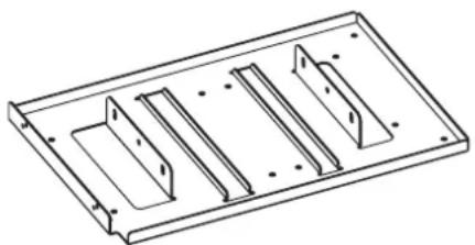 | This is used to install the projector itself.The bracket has a function for adjusting horizontal tilt. |
Hex head bolt, captive washer <6>(M6 × 16) | These are used to mount the bracket onto the projector. |
Hex head bolt, captive washer <4>(M10 × 40) | Prevents the projector from falling. |
Wire rope <4>Approx. 2.0 mm (3/32") wire diameter,800 mm (31-1/2") length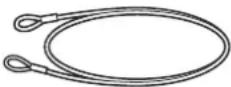 |
● Tightening torque for the screws are M6: 4±0.5 N•m, M10: 20±1 N•m.
- When tightening up the screws, use a tool such as a torque screwdriver or torque wrench. Do not use electric screwdrivers or impact screwdrivers.
Attention
- Dispose of the packaging materials properly after taking the product out of it.
- Store small parts in an appropriate manner, and keep them away from small children.
Standard installation dimensions
The dimensional relationship between the screen and the projector is shown below.
Establish the dimensions after assessing the area possible for installation.
The zoom function of the lens allows you to adjust the projection distance. Fine adjust while checking the projected image.
When any of the following lens is attached, the dimensional relationship between the screen and the projector will differ from that of other lens.
- Zoom lens (model number: ET-D3LEW200)
● Fixed-focus lens (model number: ET-D3LEU100 / ET-D75LE95 / ET-D75LE90)
● Fisheye lens (model number: ET-D3LEF70)
For details, refer to the following.
"
"
“
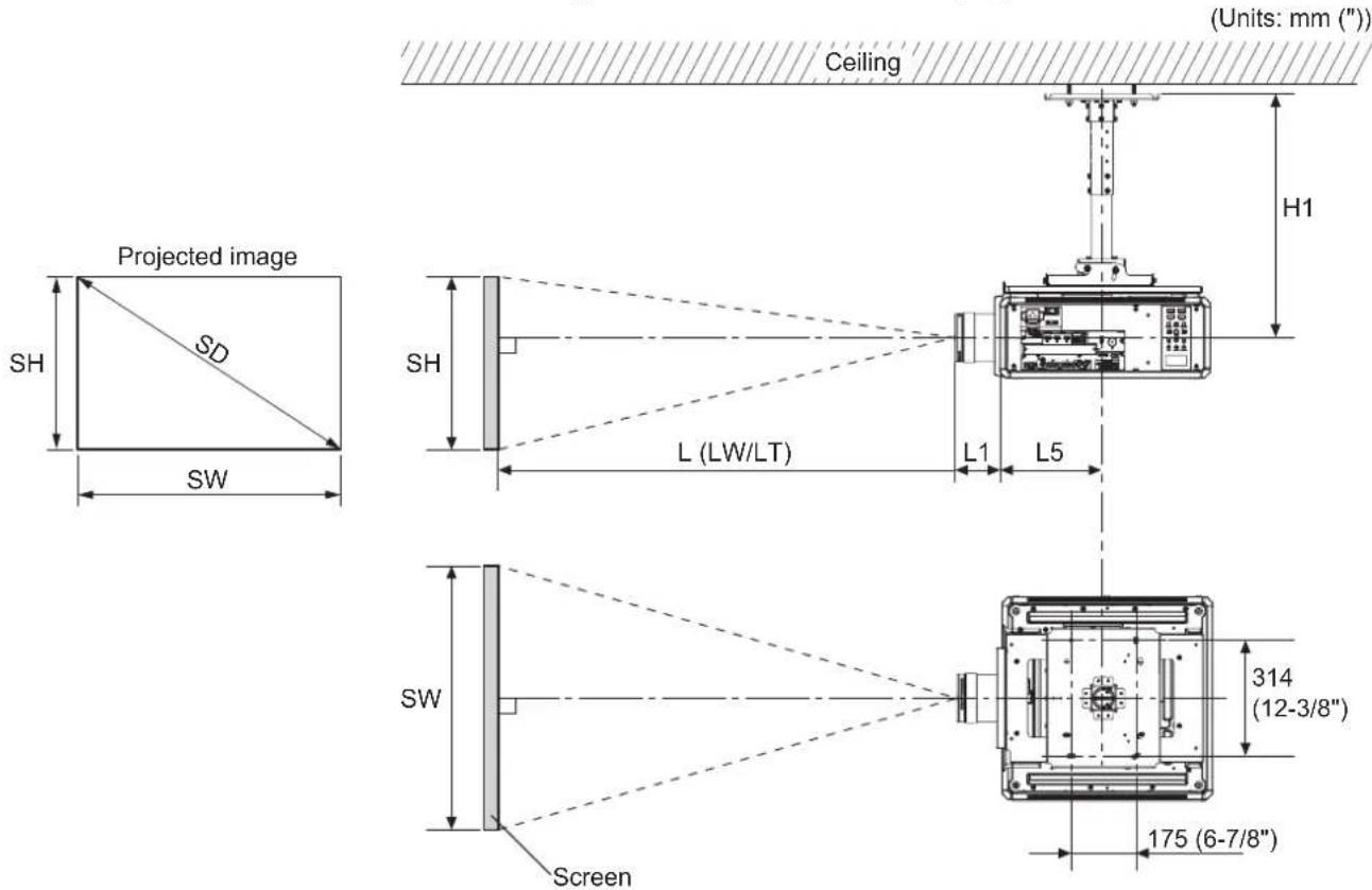
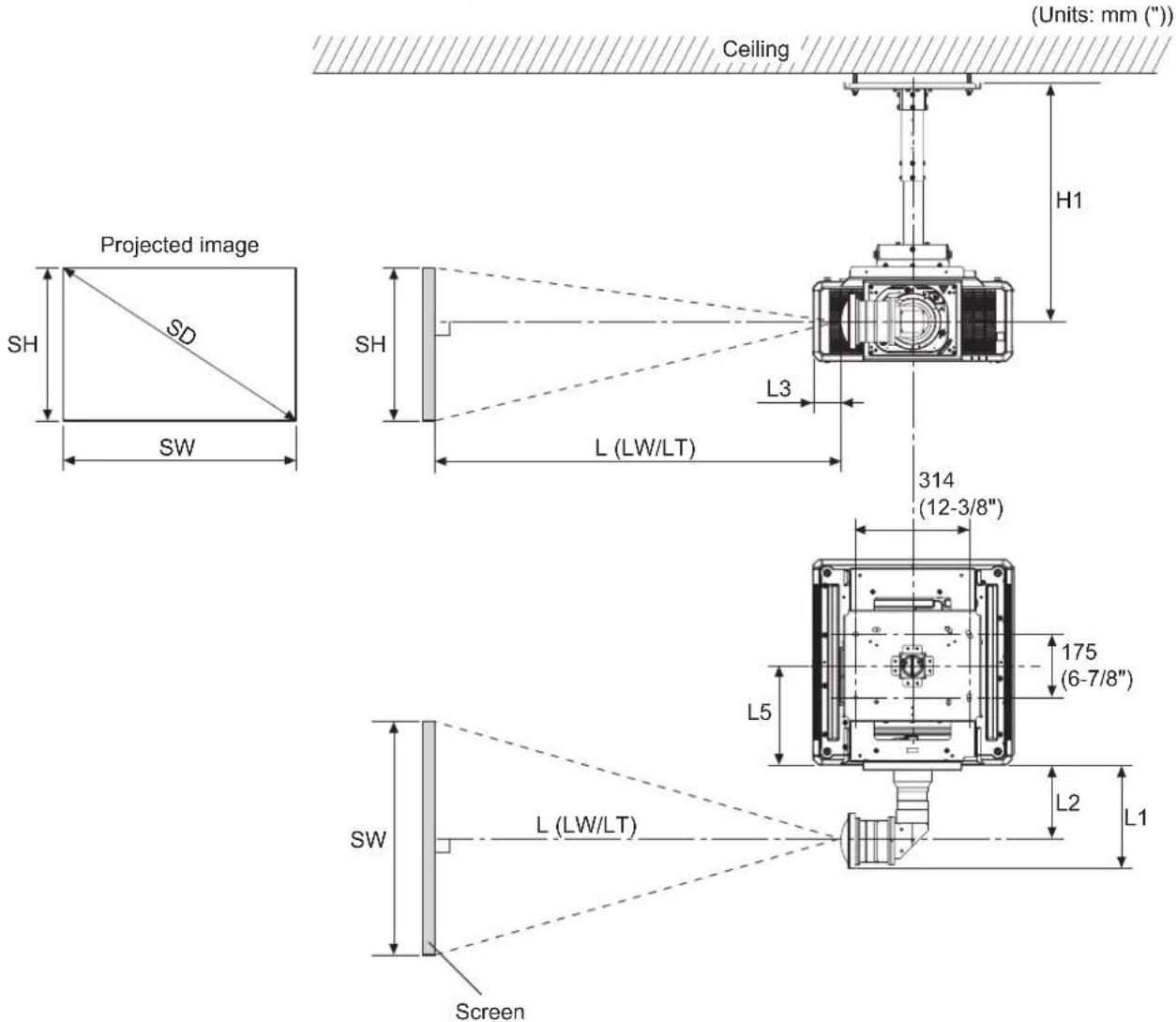
■ Dimensional relationship diagram
● The illustration shows the ET-PKD520H ceiling mount bracket mounted on a projector.
Note
- This illustration assumes that the projector will be installed so that the projected image fills the screen and is properly aligned with it.
● This drawing is not in exact scale.
| SH | Image height | L1 | Lens protrusion dimension (from front of set to tip of lens) |
| SW | Image width | L5 | From front center of the attachment plate to front of projector |
| SD Projected image size | H1 | From lens center to attachment plate (includes the thickness of the attachment plate) | |
| L Projection distance | |||
Standard installation dimensions (continued)
Attention
- Install the projector at a sufficient distance from the surrounding walls and objects so that the air intake and exhaust ports of the projector are not blocked. For details on the distance, refer to the operating instructions for your projector.
- Avoid setting up in places which are subject to sudden temperature changes, such as near an air conditioner or lighting equipment (studio lamps, etc.).
Note
- When [GEOMETRY] is used, correction is performed in the direction that results in a screen smaller than the specified screen size.
- The illustrations of projectors in this manual are for informational purposes only and do not represent a specific model. Configurations may vary with the model.
■ Dimensional relationship
● H1 and L5 values
(Unit: m)
| PT-RQ25K / RQ18K / RZ24K / RZ17K / RZ14K | PT-RQ22K / RZ21K / RS20K / RZ16K / RQ13K / RZ12K / RS11K | ||
| ET-PKD520H | H1 0.540 | -0.660 0.562 | -0.682 |
| L5 0.275 0.298 | |||
| ET-PKD520S | H1 0.226 0.248 | ||
| L5 0.275 0.298 | |||
- L1 values
(Unit: m)
| PT-RQ25K / RQ18K / RZ24K / RZ17K / RZ14K | PT-RQ22K / RZ21K / RS20K / RZ16K | |
| ET-D3LEW10 0.211 0.210 | ||
| ET-D75LE10 0.126 | 0.125 | |
| ET-D75LES20/ET-D75LE20 | 0.122 | 0.121 |
| ET-D3LET30 | 0.179 0.178 | |
| ET-D75LE30 | 0.122 | 0.121 |
| ET-D3LET40 | 0.135 | 0.135 |
| ET-D75LE40 | 0.124 | 0.124 |
| ET-D75LEW50/ET-D75LE50 | 0.204 0.203 | |
| ET-D3LEW60/ET-D75LE6 | 0.213 | 0.212 |
| ET-D3LET80/ET-D75LE8 | 0.263 0.262 | |
(Unit: m)
| PT-RQ13K / RZ12K / RS11K | |
| ET-D75LE6 | 0.212 |
| ET-D75LE8 | 0.262 |
| ET-D75LE10 | 0.125 |
| ET-D75LE20 | 0.121 |
| ET-D75LE30 | 0.121 |
| ET-D75LE40 | 0.124 |
| ET-D75LEW50/ET-D75LE50 | 0.203 |
● Formulas for calculating projection distance by projection lens
Check the projected image size SD (m) and use the following formula to determine projection distance.
(Values obtained by the calculation formulas in the tables below contain a slight error.)
When calculating a projection distance using image size designation (value in inches), multiply the value in inches by 0.0254 and substitute it into SD in the formula for calculating the projection distance.
Note
- The throw ratios are based on values during projection of 3.81 m (150") projected image size.
Standard installation dimensions (continued)
PT-RQ25K / RQ18K / RZ24K / RZ17K / RZ14K
(Unit: m)
| Projection Lens | Throw ratio Aspect ratio | Projection distance (L) formula | ||
| Min. (LW) Max. (LT) | ||||
| ET-D3LEW60/ET-D75LE6 | 1.11 - 1.32 : 1 16:10 = 0.9574 × SD | - 0.0566 = 1.1471 × SD | - 0.0736 | |
| 1.11 - 1.33 : 1 16:9 = 0.9841 × SD | - 0.0566 = 1.1790 × SD | - 0.0736 | ||
| 1.34 - 1.59 : 1 4:3 = 1.0839 × SD | - 0.0566 = 1.2986 × SD | - 0.0736 | ||
| ET-D3LEW10 | 1.52 - 2.07 : 1 | 16:10 = 1.3063 × SD | - 0.0867 = 1.7852 × SD | - 0.10 25 |
| 16:9 = 1.3426 × SD | - 0.0867 = 1.8348 × SD | - 0.10 25 | ||
| 1.83 - 2.49 : 1 | 4:3 | = 1.4788 × SD - 0.0867 = 2.0209 × SD | - 0.10 25 | |
| ET-D75LE10 | 1.56 - 2.01 : 1 | 16:10 = 1.3423 × SD | - 0.0857 = 1.7349 × SD | - 0.10 8 5 |
| 16:9 = 1.3796 × SD | - 0.0857 | = 1.7831 × SD - 0.10 8 5 | ||
| 1.88 - 2.41 : 1 4:3 = 1.5196 × SD - 0.0857 | = 1.9641 × SD - 0.10 8 5 | |||
| ET-D75LES20/ET-D75LE20 | 2.00 - 2.90 : 1 | 16:10 | = 1.7174 × SD - 0.0832 | = 2.4954 × SD - 0.1162 |
| 2.01 - 2.90 : 1 | 16:9 | = 1.7651 × SD - 0.0832 | = 2.5648 × SD - 0.1162 | |
| 2.41 - 3.49 : 1 4:3 = 1.9442 × SD - 0.0832 = 2.8250 × SD - 0.1162 | ||||
| ET-D3LET30 | 2.88 - 5.61 : 1 | 16:10 | = 2.4730 × SD - 0.1261 | = 4.8101 × SD - 0.18 92 |
| 16:9 | = 2.5418 × SD - 0.1261 | = 4.9438 × SD - 0.18 92 | ||
| 3.46 - 6.74 : 1 | 4:3 = 2.7997 × SD - 0.1261 | = 5.4454 × SD - 0.18 92 | ||
| ET-D75LE30 | 2.89 - 5.61 : 1 | 16:10 | = 2.4776 × SD - 0.1131 | = 4.8050 × SD - 0.1765 |
| 16:9 | = 2.5465 × SD - 0.1131 | = 4.9386 × SD - 0.1765 | ||
| 3.47 - 6.74 : 1 4:3 = 2.8048 × SD - 0.1131 | = 5.4396 × SD - 0.1765 | |||
| ET-D3LET40 | 5.54 - 8.90 : 1 | 16:10 | = 4.7403 × SD - 0.1673 | = 7.5996 × SD - 0.1846 |
| 16:9 | = 4.8721 × SD - 0.1673 | = 7.8109 × SD - 0.1846 | ||
| 6.66 - 10.7 : 1 4:3 = 5.3664 × SD - 0.1673 | = 8.6033 × SD - 0.1846 | |||
| ET-D75LE40 | 5.55 - 8.86 : 1 | 16:10 | = 4.7439 × SD - 0.1577 | = 7.5632 × SD - 0.1615 |
| 5.55 - 8.87 : 1 | 16:9 | = 4.8758 × SD - 0.1577 | = 7.7735 × SD - 0.1615 | |
| 6.67 - 10.6 : 1 | 4:3 = 5.3704 × SD - 0.1577 | = 8.5622 × SD - 0.1615 | ||
| ET-D3LET80/ET-D75LE8 | 8.83 - 16.6 : 1 | 16:10 = 7.5832 × SD - 0.3862 | = 14.2081 × SD - 0.3598 | |
| 16:9 | = 7.7940 × SD - 0.3862 | = 14.6031 × SD - 0.3598 | ||
| 10.6 - 19.9 : 1 4:3 = 8.5848 × SD - 0.3862 | = 16.0846 × SD - 0.3598 | |||
| ET-D75LEW50/ET-D75LE50 | 0.838 : 1 | 16:10 | = 0.7286 × SD - 0.0713 | |
| 16:9 | = 0.7488 × SD - 0.0713 | |||
| 1.01 : 1 | 4:3 | = 0.8248 × SD - 0.0713 | ||
PT-RQ22K
(Unit: m)
| Projection Lens | Throw ratio Aspect ratio | Projection distance (L) formula | ||
| Min. (LW) Max. (LT) | ||||
| ET-D3LEW60/ET-D75LE6 | 1.00 - 1.18 : 1 | 16:10 = 0.8549 × SD | - 0.0566 = 1.0242 × SD | - 0.0736 |
| 16:9 | = 0.8786 × SD - 0.0566 | = 1.0527 × SD - 0.0736 | ||
| 1.20 - 1.42 : 1 | 4:3 | = 0.9679 × SD - 0.0566 | = 1.1596 × SD - 0.0736 | |
| ET-D3LEW10 | 1.35 - 1.84 : 1 | 16:10 | = 1.1663 × SD - 0.0867 | = 1.5939 × SD - 0.10 25 |
| 16:9 | = 1.1988 × SD - 0.0867 | = 1.6382 × SD - 0.10 25 | ||
| 1.63 - 2.22 : 1 | 4:3 = 1.3205 × SD | - 0.0867 | = 1.8046 × SD - 0.10 25 | |
| ET-D75LE10 | 1.39 - 1.79 : 1 | 16:10 | = 1.1985 × SD - 0.0857 = 1.5490 × SD | - 0.10 8 5 |
| 16:9 | = 1.2318 × SD - 0.0857 | = 1.5921 × SD - 0.10 8 5 | ||
| 1.67 - 2.15 : 1 | 4:3 = 1.3569 × SD | - 0.0857 | = 1.7538 × SD - 0.10 8 5 | |
| ET-D75LES20/ET-D75LE20 | 1.79 - 2.59 : 1 | 16:10 = 1.5334 × SD | - 0.0832 | = 2.2280 × SD - 0.1162 |
| 16:9 = 1.5760 × SD | - 0.0832 = 2.2900 × SD | - 0.1162 | ||
| 2.15 - 3.11 : 1 | 4:3 | = 1.7361 × SD - 0.0832 | = 2.5226 × SD - 0.1162 | |
(continued)
Standard installation dimensions (continued)
| Projection Lens | Throw ratio Aspect ratio | Projection distance (L) formula | ||
| Min. (LW) Max. (LT) | ||||
| ET-D3LET30 | 2.57 - 5.00 : 1 | 16:10 = 2.2081 × SD | - 0.1261 = 4.2947 × SD | - 0.1892 |
| 16:9 = 2.2695 × SD | - 0.1261 = 4.4141 × SD | - 0.1892 | ||
| 3.09 - 6.01 : 1 4:3 = 2.5000 × SD | - 0.1261 = 4.8624 × SD | - 0.1892 | ||
| ET-D75LE30 | 2.58 - 5.00 : 1 | 16:10 = 2.2121 × SD | - 0.1131 = 4.2901 × SD | - 0.1765 |
| 16:9 = 2.2736 × SD | - 0.1131 | = 4.4094 × SD - 0.1765 | ||
| 3.10 - 6.01 : 1 | 4:3 = 2.5046 × SD | - 0.1131 | = 4.8573 × SD - 0.1765 | |
| ET-D3LET40 | 4.94 - 7.94 : 1 | 16:10 = 4.2324 × SD | - 0.1673 | = 6.7853 × SD - 0.1846 |
| 4.95 - 7.94 : 1 | 16:9 = 4.3501 × SD | - 0.1673 | = 6.9740 × SD - 0.1846 | |
| 5.94 - 9.54 : 1 4:3 = 4.7919 × SD | - 0.1673 = 7.6823 × SD | - 0.1846 | ||
| ET-D75LE40 | 4.95 - 7.91 : 1 | 16:10 | = 4.2356 × SD - 0.1577 = 6.7529 × SD | - 0.1615 |
| 16:9 = 4.3534 × SD | - 0.1577 = 6.9406 × SD | - 0.1615 | ||
| 5.95 - 9.50 : 1 4:3 = 4.7955 × SD | - 0.1577 | = 7.6456 × SD - 0.1615 | ||
| ET-D3LET80/ET-D75LE8 | 7.87 - 14.8 : 1 | 16:10 | = 6.7707 × SD - 0.3862 | = 12.6858 × SD - 0.3598 |
| 16:9 = 6.9590 × SD | - 0.3862 = 13.0385 × SD | - 0.3598 | ||
| 9.46 - 17.8 : 1 | 4:3 | = 7.6658 × SD - 0.3862 | = 14.3627 × SD - 0.3598 | |
| ET-D75LEW50/ET-D75LE50 | 0.746 : 1 | 16:10 | = 0.6505 × SD - 0.0713 | |
| 16:9 | = 0.6686 × SD - 0.0713 | |||
| 0.898 : 1 | 4:3 | = 0.7365 × SD - 0.0713 | ||
PT-RQ13K
(Unit: m)
| Projection Lens | Throw ratio | Aspect ratio | Projection distance (L) formula | |
| Min. (LW) | Max. (LT) | |||
| ET-D75LE6 | 1.0 - 1.2 : 1 | 16 : 10 | = 0.8549 × SD - 0.0566 | = 1.0242 × SD - 0.0736 |
| 16 : 9 | = 0.8786 × SD - 0.0566 | = 1.0527 × SD - 0.0736 | ||
| 1.2 - 1.4 : 1 4 : 3 = 0.9679 × SD - 0.0566 = 1.1596 × SD - 0.0736 | 3 = 16 : 10 | = 1.1985 × SD - 0.0857 | = 1.5490 × SD - 0.1085 | |
| ET-D75LE10 | 1.4 - 1.8 : 1 | 16 : 9 | = 1.2318 × SD - 0.0857 | = 1.5921 × SD - 0.1085 |
| 1.7 - 2.2 : 1 4 : 3 = 1.3569 × SD - 0.0857 = 1.7538 × SD - 0.1085 | 3 = 16 : 10 | = 1.5334 × SD - 0.0832 | = 2.2280 × SD - 0.1162 | |
| ET-D75LE20 | 1.8 - 2.6 : 1 | 16 : 9 | = 1.5760 × SD - 0.0832 | = 2.2900 × SD - 0.1162 |
| 2.1 - 3.1 : 1 | 4 : 3 | = 1.7361 × SD - 0.0832 | = 2.5226 × SD - 0.1162 | |
| ET-D75LE30 | 2.6 - 5.0 : 1 | 16 : 10 | = 2.2121 × SD - 0.1131 | = 4.2901 × SD - 0.1765 |
| 16 : 9 | = 2.2736 × SD - 0.1131 | = 4.4094 × SD - 0.1765 | ||
| 3.1 - 6.0 : 1 4 : 3 = 2.5046 × SD - 0.1131 = 4.8573 × SD - 0.1765 | 3 = 16 : 10 | = 4.2356 × SD - 0.1577 | = 6.7529 × SD - 0.1615 | |
| ET-D75LE40 | 4.9 - 7.9 : 1 | 16 : 9 | = 4.3534 × SD - 0.1577 | = 6.9406 × SD - 0.1615 |
| 5.9 - 9.5 : 1 | 4 : 3 | = 4.7955 × SD - 0.1577 = 7.6456 × SD - 0.1615 | = 12.6858 × SD - 0.3598 | |
| ET-D75LE8 | 7.9 - 13.8 : 1 | 16 : 10 | = 6.7707 × SD - 0.3862 | = 13.0385 × SD - 0.3598 |
| 16 : 9 | = 6.9590 × SD - 0.3862 | = 14.3627 × SD - 0.3598 | ||
| 9.5 - 13.8 : 1 | 4 : 3 | = 7.6658 × SD - 0.3862 | = 14.3627 × SD - 0.3598 | |
| ET-D75LEW50/ET-D75LE50 | 0.7 : 1 | 16 : 10 | = 0.6505 × SD - 0.0713 | |
| 16 : 9 | = 0.6686 × SD - 0.0713 | |||
| 0.9 : 1 | 4 : 3 | = 0.7365 × SD - 0.0713 | ||
Standard installation dimensions (continued)
PT-RZ21K / RZ16K
(Unit: m)
| Projection Lens | Throw ratio Aspect ratio | Projection distance (L) formula | ||
| Min. (LW) Max. (LT) | ||||
| ET-D3LEW60/ET-D75LE6 | 0.924 - 1.10 : 1 | 16:10 = 0.7979 × SD | - 0.0566 = 0.9559 × SD | - 0.0736 |
| 16:9 = 0.8201 × SD | - 0.0566 = 0.9825 × SD | - 0.0736 | ||
| 1.12 - 1.32 : 1 4:3 = 0.9032 × SD | - 0.0566 = 1.0822 × SD | - 0.0736 | ||
| ET-D3LEW10 | 1.26 - 1.72 : 1 | 16:10 = 1.0886 × SD | - 0.0867 = 1.4876 × SD | - 0.10 25 |
| 16:9 = 1.1188 × SD | - 0.0867 = 1.5290 × SD | - 0.10 25 | ||
| 1.52 - 2.07 : 1 4:3 = 1.2324 × SD | - 0.0867 = 1.6841 × SD | - 0.10 25 | ||
| ET-D75LE10 | 1.30 - 1.67 : 1 | 16:10 | = 1.1186 × SD - 0.0857 | = 1.4458 × SD - 0.10 85 |
| 16:9 = 1.1497 × SD | - 0.0857 | = 1.4860 × SD - 0.10 85 | ||
| 1.56 - 2.01 : 1 4:3 = 1.2663 × SD | - 0.0857 = 1.6367 × SD | - 0.10 85 | ||
| ET-D75LES20/ET-D75LE20 | 1.67 - 2.41 : 1 | 16:10 | = 1.4312 × SD - 0.0832 | = 2.0795 × SD - 0.1162 |
| 16:9 | = 1.4709 × SD - 0.0832 | = 2.1373 × SD - 0.1162 | ||
| 2.00 - 2.90 : 1 | 4:3 = 1.6202 × SD | - 0.0832 = 2.3542 × SD | - 0.1162 | |
| ET-D3LET30 | 2.40 - 4.66 : 1 | 16:10 | = 2.0609 × SD - 0.1261 | = 4.0084 × SD - 0.18 92 |
| 16:9 = 2.1182 × SD | - 0.1261 | = 4.1198 × SD - 0.18 92 | ||
| 2.88 - 5.61 : 1 | 4:3 | = 2.3331 × SD - 0.1261 | = 4.5378 × SD - 0.18 92 | |
| ET-D75LE30 | 2.40 - 4.66 : 1 | 16:10 | = 2.0647 × SD - 0.1131 | = 4.0041 × SD - 0.1765 |
| 2.41 - 4.66 : 1 | 16:9 = 2.1221 × SD | - 0.1131 | = 4.1155 × SD - 0.1765 | |
| 2.89 - 5.60 : 1 | 4:3 | = 2.3374 × SD - 0.1131 | = 4.5330 × SD - 0.1765 | |
| ET-D3LET40 | 4.61 - 7.41 : 1 | 16:10 | = 3.9505 × SD - 0.1673 = 6.3330 × SD | - 0.18 4 6 |
| 16:9 | = 4.0601 × SD - 0.1673 = 6.5091 × SD | - 0.18 4 6 | ||
| 5.54 - 8.90 : 1 | 4:3 | = 4.4720 × SD - 0.1673 | = 7.1694 × SD - 0.18 4 6 | |
| ET-D75LE40 | 4.62 - 7.38 : 1 | 16:10 | = 3.9532 × SD - 0.1577 | = 6.3027 × SD - 0.1615 |
| 16:9 | = 4.0631 × SD - 0.1577 | = 6.4779 × SD - 0.1615 | ||
| 5.55 - 8.86 : 1 | 4:3 | = 4.4754 × SD - 0.1577 | = 7.1351 × SD - 0.1615 | |
| ET-D3LET80/ET-D75LE8 | 7.34 - 13.8 : 1 | 16:10 = 6.3193 × SD | - 0.3862 | = 11.8400 × SD - 0.3598 |
| 16:9 | = 6.4950 × SD - 0.3862 | = 12.1692 × SD - 0.3598 | ||
| 8.82 - 16.6 : 1 | 4:3 | = 7.1540 × SD - 0.3862 = 13.4039 × SD | - 0.3598 | |
| ET-D75LEW50/ET-D75LE50 | 0.694 : 1 | 16:10 | = 0.6072 × SD - 0.0713 | |
| 0.695 : 1 | 16:9 | = 0.6240 × SD - 0.0713 | ||
| 0.836 : 1 | 4:3 | = 0.6873 × SD - 0.0713 | ||
Standard installation dimensions (continued)
PT-RZ12K
(Unit: m)
| Projection Lens | Throw ratio Aspect ratio | Projection distance (L) formula | ||
| Min. (LW) Max. (LT) | ||||
| ET-D75LE6 | 0.924 - 1.10 : 1 | 16 : 10 = 0 | 7979 × SD - 0.0566 = 0.9 | 559 × SD - 0.0736 |
| 16 : 9 = 0.8 | 201 × SD - 0.0566 = 0.9 | 825 × SD - 0.0736 | ||
| 1.12 - 1.32 : 1 | : 3 = 0.9032 × SD | - 0.0566 = 1.0 | 822 × SD - 0.0736 | |
| ET-D75LE10 | 1.30 - 1.67 : 1 | 16 : 10 = 1.1 | 1186 × SD - 0.0857 = 1.4 | 458 × SD - 0.1085 |
| 16 : 9 = 1.1 | 497 × SD - 0.0857 = 1.4 | 860 × SD - 0.1085 | ||
| 1.56 - 2.01 : 1 | : 3 = 1.2663 × SD | - 0.0857 = 1.6 | 367 × SD - 0.1085 | |
| ET-D75LE20 | 1.67 - 2.41 : 1 | 16 : 10 | = 1.4312 × SD - 0.0832 = 2.0 | 795 × SD - 0.1162 |
| 16 : 9 | = 1.4709 × SD - 0.0832 | = 2.1373 × SD - 0.1162 | ||
| 2.00 - 2.90 : 1 | : 3 = 1.6202 × SD | - 0.0832 | = 2.3542 × SD - 0.1162 | |
| ET-D75LE30 | 2.40 - 4.66 : 1 | 16 : 10 = 2.0 | 0647 × SD - 0.1131 | = 4.0041 × SD - 0.1765 |
| 2.41 - 4.66 : 1 | 16 : 9 = 2.1 | 1221 × SD - 0.1131 | = 4.1155 × SD - 0.1765 | |
| 2.89 - 5.60 : 1 | 4 : 3 | = 2.3374 × SD - 0.1131 | = 4.5330 × SD - 0.1765 | |
| ET-D75LE40 | 4.62 - 7.38 : 1 | 16 : 10 | = 3.9532 × SD - 0.1577 | = 6.3027 × SD - 0.1615 |
| 16 : 9 = 4.0 | 0631 × SD - 0.1577 | = 6.4779 × SD - 0.1615 | ||
| 5.55 - 8.86 : 1 | 4 : 3 = 4.4 | 754 × SD - 0.1577 | = 7.1351 × SD - 0.1615 | |
| ET-D75LE8 | 7.34 - 13.8 : 1 | 16 : 10 = 6.1 | 3193 × SD - 0.3862 | = 11.8400 × SD - 0.3598 |
| 16 : 9 = 6.4 | 4950 × SD - 0.3862 | = 12.1692 × SD - 0.3598 | ||
| 8.82 - 16.6 : 1 | 4 : 3 | = 7.1540 × SD - 0.3862 = 13 | 4039 × SD - 0.3598 | |
| ET-D75LE50 | 0.694 : 1 | 16 : 10 | = 0.6072 × SD - 0.0713 | |
| 0.695 : 1 | 16 : 9 | = 0.6240 × SD - 0.0713 | ||
| 0.836 : 1 | 4 : 3 | = 0.6873 × SD - 0.0713 | ||
PT-RS20K
(Unit: m)
| Projection Lens | Throw ratio | Aspect ratio | Projection distance (L) formula | |
| Min. (LW) | Max. (LT) | |||
| ET-D3LEW60/ET-D75LE6 | 1.01 - 1.19 : 1 | 4:3 | = 0.8150 × SD - 0.0566 | = 0.9764 × SD - 0.0736 |
| 16:9 | = 0.8877 × SD - 0.0566 | = 1.0636 × SD - 0.0736 | ||
| ET-D3LEW10 | 1.37 - 1.86 : 1 | 4:3 | = 1.1119 × SD - 0.0867 | = 1.5195 × SD - 0.1025 |
| 16:9 | = 1.2112 × SD - 0.0867 | = 1.6552 × SD - 0.1025 | ||
| ET-D75LE10 | 1.41 - 1.81 : 1 | 4:3 | = 1.1425 × SD - 0.0857 | = 1.4767 × SD - 0.1085 |
| 16:9 | = 1.2446 × SD - 0.0857 | = 1.6086 × SD - 0.1085 | ||
| ET-D75LES20/ET-D75LE20 | 1.80 - 2.61 : 1 | 4:3 | = 1.4618 × SD - 0.0832 | = 2.1241 × SD - 0.1162 |
| 1.81 - 2.61 : 1 | 16:9 | = 1.5924 × SD - 0.0832 | = 2.3137 × SD - 0.1162 | |
| ET-D3LET30 | 2.59 - 5.05 : 1 | 4:3 | = 2.1050 × SD - 0.1261 | = 4.0943 × SD - 0.1892 |
| 2.60 - 5.06 : 1 | 16:9 | = 2.2930 × SD - 0.1261 | = 4.4599 × SD - 0.1892 | |
| ET-D75LE30 | 2.60 - 5.05 : 1 | 4:3 | = 2.1089 × SD - 0.1131 | = 4.0899 × SD - 0.1765 |
| 2.61 - 5.05 : 1 | 16:9 | = 2.2972 × SD - 0.1131 | = 4.4552 × SD - 0.1765 | |
| ET-D3LET40 | 4.99 - 8.02 : 1 | 4:3 | = 4.0349 × SD - 0.1673 | = 6.4687 × SD - 0.1846 |
| 5.00 - 8.02 : 1 | 16:9 | = 4.3952 × SD - 0.1673 | = 7.0463 × SD - 0.1846 | |
| ET-D75LE40 | 5.00 - 7.99 : 1 | 4:3 | = 4.0379 × SD - 0.1577 | = 6.4377 × SD - 0.1615 |
| 16:9 | = 4.3985 × SD - 0.1577 | = 7.0126 × SD - 0.1615 | ||
| ET-D3LET80/ET-D75LE8 | 7.95 - 14.9 : 1 | 4:3 | = 6.4547 × SD - 0.3862 | = 12.0937 × SD - 0.3598 |
| 7.96 - 15.0 : 1 | 16:9 | = 7.0312 × SD - 0.3862 | = 13.1737 × SD - 0.3598 | |
| ET-D75LEW50/ET-D75LE50 | 0.752 : 1 4:3 | = 0.6202 × SD - 0.0713 | ||
| 0.754 : 1 16:9 | = 0.6755 × SD - 0.0713 | |||
Standard installation dimensions (continued)
PT-RS11K
(Unit: m)
| Projection Lens | Throw ratio Aspect ratio | Projection distance (L) formula | ||
| Min. (LW) Max. (LT) | ||||
| ET-D75LE6 1.01 - 1.19 : 1 | 4 : 3 = 0.8 | 150 × SD | - 0.0566 = 0.9 | 764 × SD - 0.0736 |
| 16 : 9 = 0.8 | 877 × SD | - 0.0566 = 1.0 | 636 × SD - 0.0736 | |
| ET-D75LE10 1.41 - 1.81 : 1 | 4 : 3 = 1.1 | 425 × SD | - 0.0857 = 1.4 | 767 × SD - 0.10 8 5 |
| 16 : 9 = 1.2 | 2446 × SD | - 0.0857 = 1.6 | 086 × SD - 0.10 8 5 | |
| ET-D75LE20 | 1.80 - 2.61 : 1 4 : 3 | = 1.4618 × SD | - 0.0832 | = 2.1241 × SD - 0.1162 |
| 1.81 - 2.61 : 1 | 16 : 9 | = 1.5924 × SD - 0.0832 = 2.3 | 137 × SD - 0.1162 | |
| ET-D75LE30 | 2.60 - 5.05 : 1 | 4 : 3 | = 2.1089 × SD - 0.1131 | = 4.0899 × SD - 0.1765 |
| 2.61 - 5.05 : 1 | 16 : 9 | = 2.2972 × SD - 0.1131 | = 4.4552 × SD - 0.1765 | |
| ET-D75LE40 | 5.00 - 7.99 : 1 | 4 : 3 = 4.0 | 379 × SD - 0.1577 | = 6.4377 × SD - 0.1615 |
| 16 : 9 | = 4.3985 × SD - 0.1577 | = 7.0126 × SD - 0.1615 | ||
| ET-D75LE8 | 7.95 - 14.9 : 1 | 4 : 3 | = 6.4547 × SD - 0.3862 | = 12.0937 × SD - 0.3598 |
| 7.96 - 15.0 : 1 | 16 : 9 | = 7.0312 × SD - 0.3862 | = 13.1737 × SD - 0.3598 | |
| ET-D75LE50 | 0.752 : 1 | 4 : 3 | = 0.6202 × SD - 0.0713 | |
| 0.754 : 1 | 16 : 9 | = 0.6755 × SD - 0.0713 | ||
Standard installation dimensions (continued)
The dimensional relationship between the screen and the projector is shown below.
Establish the dimensions after assessing the area possible for installation.
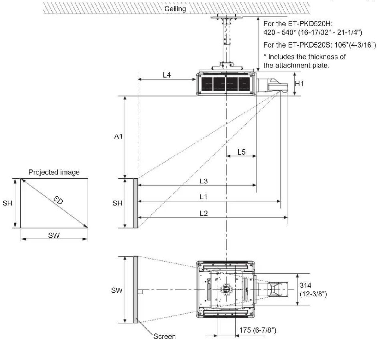
■ Dimensional relationship diagram
● The illustration shows the ET-PKD520H ceiling mount bracket mounted on a projector.
Note
● This illustration assumes that the projector will be installed so that the projected image fills the screen and is properly aligned with it.
● This drawing is not in exact scale.
● The PT-RQ13K / RZ12K / RS11K is not supported by the ET-D3LEW200.
| SH | Image height | L1 | Lens protrusion dimension (from front of set to tip of lens) |
| SW | Image width | L2 | From front of projector to center of lens |
| SD | Projected image size | L3 | From side of projector to center of lens |
| L Projection distance L5 From front center of the attachment plate to front of projector | |||
| H1 | From lens center to attachment plate (includes the thickness of the attachment plate) | ||
Standard installation dimensions (continued)
Attention
- Install the projector at a sufficient distance from the surrounding walls and objects so that the air intake and exhaust ports of the projector are not blocked. For details on the distance, refer to the operating instructions for your projector.
- Avoid setting up in places which are subject to sudden temperature changes, such as near an air conditioner or lighting equipment (studio lamps, etc.).
Note
- When [GEOMETRY] is used, correction is performed in the direction that results in a screen smaller than the specified screen size.
- The illustrations of projectors in this manual are for informational purposes only and do not represent a specific model. Configurations may vary with the model.
■ Dimensional relationship
● H1 and L5 values
(Unit: m)
| PT-RQ25K / RQ18K / RZ24K / RZ17K / RZ14K | PT-RQ22K / RZ21K / RS20K / RZ16K / RQ13K / RZ12K / RS11K | ||
| ET-PKD520H | H1 0.540 - 0.660 0.562 | - 0.682 | |
| L5 0.275 0.298 | |||
| ET-PKD520S | H1 0.226 0.248 | ||
| L5 0.275 0.298 | |||
● L1 values
(Unit: m)
| PT-RQ25K / RQ18K / RZ24K / RZ17K / RZ14K | PT-RQ22K / RZ21K / RS20K / RZ16K | PT-RQ13K / RZ12K / RS11K | |
| ET-D3LEU100 0.286 0.285 0.285 | |||
| ET-D3LEW200 | 0.352 | 0.351 | - |
- L2 values
(Unit: m)
| PT-RQ25K / RQ18K / RZ24K / RZ17K / RZ14K | PT-RQ22K / RZ21K / RS20K / RZ16K | PT-RQ13K / RZ12K / RS11K | |
| ET-D3LEU100 | 0.210 0.209 0.209 | ||
| ET-D3LEW200 0.255 0 | 255 | - |
- L3 values
(Unit: m)
| PT-RQ25K / RQ18K / RZ24K / RZ17K / RZ14K | PT-RQ22K / RZ21K / RS20K / RZ16K | PT-RQ13K / RZ12K / RS11K | |
| ET-D3LEU100 | 0.077 | 0.101 | 0.091 |
| ET-D3LEW200 | 0.102 | 0.126 | - |
- Formulas for calculating projection distance by projection lens
Check the projected image size SD (m) and use the following formula to determine projection distance.
(Values obtained by the calculation formulas in the tables below contain a slight error.)
When calculating a projection distance using image size designation (value in inches), multiply the value in inches by 0.0254 and substitute it into SD in the formula for calculating the projection distance.
Note
● The throw ratios are based on values during projection of 3.81 m (150") projected image size.
Standard installation dimensions (continued)
ET-D3LEU100
(Unit: m)
| Projector | Throw ratio | Aspect ratio | Projection distance (L) formula |
| PT-RQ25K / PT-RQ18K / PT-RZ24K / PT-RZ17K / PT-RZ14K | 0.447 : 1 | 16:10 = 0.3917 × SD | - 0.0664 |
| 16:9 = 0.4025 × SD | - 0.0664 | ||
| 0.538 : 1 4:3 = | 0.4434 × SD | - 0.0664 | |
| PT-RQ22K / PT-RQ13K | 0.397 : 1 16:10 | = 0.3497 × SD | - 0.0664 |
| 0.398 : 1 16:9 = | 0.3594 × SD | - 0.0664 | |
| 0.479 : 1 4:3 = | 0.3959 × SD | - 0.0664 | |
| PT-RZ21K / PT-RZ16K / PT-RZ12K | 0.370 : 1 | 16:10 = 0.3264 × SD | - 0.0664 |
| 16:9 = 0.3355 × SD | - 0.0664 | ||
| 0.446 : 1 4:3 = | 0.3695 × SD | - 0.0664 | |
| PT-RS20K / PT-RS11K | 0.402 : 1 16:9 | = 0.3631 × SD - 0.0664 | |
| 0.401 : 1 4:3 = | 0.3334 × SD | - 0.0664 |
ET-D3LEW200
(Unit: m)
| Projector Throw ratio Aspect ratio | Projection distance (L) formula | |||
| Min. (LW) | Max. (LT) | |||
| PT-RQ25K / PT-RQ18K / PT-RZ24K / PT-RZ17K / PT-RZ14K | 0.779 – 1.025 : 1 | 16:10 | = 0.6798 × SD – 0.10 01 | = 0.8910 × SD – 0.1076 |
| 0.780 – 1.026 : 1 | 16:9 = 0.6987 × SD – 0.10 01 | = 0.9158 × SD – 0.1076 | ||
| 0.938 – 1.23 : 1 | 4:3 | = 0.7696 × SD – 0.10 01 | = 1.0087 × SD – 0.1076 | |
| PT-RQ22K | 0.693 – 0.913 : 1 | 16:10 | = 0.6070 × SD – 0.10 01 | = 0.7956 × SD – 0.1076 |
| 0.694 – 0.913 : 1 | 16:9 | = 0.6239 × SD – 0.10 01 | = 0.8177 × SD – 0.1076 | |
| 0.835 – 1.09 : 1 | 4:3 | = 0.6872 × SD – 0.10 01 | = 0.9007 × SD – 0.1076 | |
| PT-RZ21K / PT-RZ16K | 0.645 – 0.850 : 1 | 16:10 | = 0.5665 × SD – 0.10 01 | = 0.7425 × SD – 0.1076 |
| 0.646 – 0.851 : 1 | 16:9 = 0.5823 × SD – 0.10 01 | = 0.7632 × SD – 0.1076 | ||
| 0.778 – 1.02 : 1 | 4:3 | = 0.6414 × SD – 0.10 01 | = 0.8406 × SD – 0.1076 | |
| PT-RS20K | 0.701 – 0.923 : 1 | 16:9 = 0.6303 × SD – 0.10 01 | = 0.8262 × SD – 0.1076 | |
| 0.699 – 0.921 : 1 | 4:3 | = 0.5787 × SD – 0.10 01 | = 0.7584 × SD – 0.1076 | |
Standard installation dimensions (continued)
The dimensional relationship between the screen and the projector is shown below.
Establish the dimensions after assessing the area possible for installation.
■ Dimensional relationship diagram
● The illustration shows the ET-PKD520H ceiling mount bracket mounted on a projector.
(Units: mm ("))
Note
- This illustration assumes that the projector will be installed so that the projected image fills the screen and is properly aligned with it.
● This drawing is not in exact scale.
● The PT-RQ25K / RQ18K / RZ24K / RZ17K / RZ14K is not supported by the ET-D75LE90.
| SH | Image height | L4 | From screen to rear of projector |
| SW Image width L5 | From center of attachment plate to front of projector | ||
| SD | Projected image size | A1 | From top edge of screen to top of projector |
| L1 | Projection distance (from screen to mirror reflective surface*) | H1 | From bottom of set (the surface in contact with this product) to top of projector |
| L2 From screen to tip of lens | |||
| L3 From screen to front of projector | |||
* The mirror reflective surface is inside the fixed-focus lens, and is not visible from the outside.
Standard installation dimensions (continued)
Attention
- Install the projector at a sufficient distance from the surrounding walls and objects so that the air intake and exhaust ports of the projector are not blocked. For details on the distance, refer to the operating instructions for your projector.
- Avoid setting up in places which are subject to sudden temperature changes, such as near an air conditioner or lighting equipment (studio lamps, etc.).
- Regardless of the projector model, set up the projector so that the projected image is rectangular and the back of the projector and the screen are parallel. Depending on your projector, however, keystone distortion correction via the [GEOMETRY] function may be possible, even after setup. For details, refer to "Setting up" in the operating instructions of the projector.
Note
- Dimension L4 is not the distance from the projector rear panel to the wall, but the distance from the projector rear panel to the screen.
- When [GEOMETRY] is used, correction is performed in the direction that results in a screen smaller than the specified screen size.
- The illustrations of projectors in this manual are for informational purposes only and do not represent a specific model. Configurations may vary with the model.
■Dimensional relationship
● H1 and L5 values
(Unit: m)
| PT-RQ25K / RQ18K / RZ24K / RZ17K / RZ14K | PT-RQ22K / RZ21K / RS20K / RZ16K / RQ13K / RZ12K / RS11K | |
| H1 | 0.230 0.270 | |
| L5 | 0.275 0.298 |
● L1, A1 calculation formula
Check the projected image size SD (m) and use each formula to determine projection distance (L1) and top of set to top edge of screen (A1).
By determining L1 and A1, you can calculate all other dimensions.
(Values obtained by the calculation formulas contain a slight error.)
When calculating a projection distance using image size designation (value in inches), multiply the value in inches by 0.0254 and substitute it into SD in the formula for calculating the projection distance.
PT-RQ25K / RQ18K
(Unit: m)
| Aspect ratio 16 : 10(Throw ratio [0.39 : 1]) | Aspect ratio 16 : 9(Throw ratio [0.39 : 1]) | Aspect ratio 4 : 3(Throw ratio [0.47 : 1]) | ||
| L1 = 0.364 × SD + 0.020 = 0.374 × SD + 0.020 = 0.412 × SD + 0.020 | ||||
| A1 | Min. = | 0.214 × SH - 0.110 = 0.293 | × SH - 0.110 = 0.214 | × SH - 0.110 |
| Max. = | 0.430 × SH - 0.110 = 0.533 | × SH - 0.110 = 0.430 | × SH - 0.110 | |
PT-RQ22K / RQ13K
(Unit: m)
| Aspect ratio 16 : 10(Throw ratio [0.39 : 1]) | Aspect ratio 16 : 9(Throw ratio [0.39 : 1]) | Aspect ratio 4 : 3(Throw ratio [0.47 : 1]) | ||
| L1 = 0.325 × SD + 0.020 = 0.334 × SD + 0.020 = 0.368 × SD + 0.020 | ||||
| A1 | Min. = 0.245 × SH - 0.128 | = 0.272 × SH - 0.128 | = 0.245 × SH - 0.128 | |
| Max. = 0.339 × SH - 0.128 | = 0.432 × SH - 0.128 | = 0.339 × SH - 0.128 | ||
PT-RZ24K / RZ17K / RZ14K
(Unit: m)
| Aspect ratio 16 : 10(Throw ratio [0.36 : 1]) | Aspect ratio 16 : 9(Throw ratio [0.36 : 1]) | Aspect ratio 4 : 3(Throw ratio [0.44 : 1]) | ||
| L1 = 0.364 × SD + 0.020 = 0.374 × SD + 0.020 = 0.412 × SD + 0.020 | ||||
| A1 | Min. = 0.214 × SH | - 0.110 = 0.293 × SH | - 0.110 = 0.214 × SH | - 0.110 |
| Max. = 0.430 × SH | - 0.110 = 0.533 × SH | - 0.110 = 0.430 × SH | - 0.110 | |
Standard installation dimensions (continued)
PT-RZ21K / RZ16K / RZ12K
(Unit: m)
| Aspect ratio 16:10(Throw ratio [0.36:1]) | Aspect ratio 16:9(Throw ratio [0.36:1]) | Aspect ratio 4:3(Throw ratio [0.44:1]) | ||
| L1=0.303×SD+0.020=0.312×SD+0.020=0.343×SD+0.020 | ||||
| A1 | Min.= | 0.229×SH-0.128=0.254 | ×SH-0.128=0.229 | ×SH-0.128 |
| Max.= | 0.283×SH-0.128=0.370 | ×SH-0.128=0.283 | ×SH-0.128 | |
PT-RS20K / RS11K
(Unit: m)
| Aspect ratio 4 : 3(Throw ratio [0.39 : 1]) | Aspect ratio 16 : 9(Throw ratio [0.39 : 1]) | ||
| L1 = 0.310 × SD + 0.020 = 0.337 × SD + 0.020 | |||
| A1 | Min. | = 0.206 × SH - 0.128 | = 0.275 × SH - 0.128 |
| Max. = | 0.441 × SH | - 0.128 | |
● L2, L3, and L4 calculation formula
(Unit: m)
| PT-RQ25K / RQ18K / RZ24K / RZ17K / RZ14K | PT-RQ22K / RZ21K / RS20K / RZ16K / RQ13K / RZ12K / RS11K | ||
| ET-D75LE95 ET-D75LE95 ET-D75LE90 | |||
| L2 | = L1 + 0.029 | = L1 + 0.029 | = L1 + 0.029 |
| L3 | = L1 - 0.293 | = L1 - 0.292 | = L1 - 0.277 |
| L4 | = L1 - 0.863 | = L1 - 1.017 | = L1 - 1.002 |
Standard installation dimensions (continued)
The dimensional relationship between the screen and the projector is shown below.
Establish the dimensions after assessing the area possible for installation.
■ Dimensional relationship diagram
● The illustration shows the ET-PKD520H ceiling mount bracket mounted on a projector.
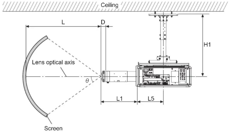
Note
- This illustration assumes that the projector will be installed so that the projected image fills the screen and is properly aligned with it.
● This drawing is not in exact scale.
| θ Projected angle L Projection distance | |||
| L1 | Lens protrusion dimension(from front of set to tip of lens) | D Exit pupil position | |
| L5 | From front center of the attachment plate to front of projector | H1 | From lens center to attachment plate(includes the thickness of the attachment plate) |
Attention
- Install the projector at a sufficient distance from the surrounding walls and objects so that the air intake and exhaust ports of the projector are not blocked. For details on the distance, refer to the operating instructions for your projector.
- Avoid setting up in places which are subject to sudden temperature changes, such as near an air conditioner or lighting equipment (studio lamps, etc.).
Standard installation dimensions (continued)
■ Dimensional relationship
● H1 and L5 values
(Unit: m)
| PT-RQ25K / RQ18K / RZ24K / RZ17K / RZ14K | PT-RQ22K / RZ21K / RS20K / RZ16K / RQ13K / RZ12K / RS11K | ||
| ET-PKD520H | H1 0.540 - 0.660 0.562 | - 0.682 | |
| L5 0.275 0.298 | |||
| ET-PKD520S | H1 0.226 0.248 | ||
| L5 0.275 0.298 | |||
● Calculation formula of L and L1 values and D
(Unit: m)
| PT-RQ25K / RQ18K / RZ24K / RZ17K / RZ14K | PT-RQ22K / RZ21K / RS20K / RZ16K / RQ13K / RZ12K / RS11K | |
| Supported projection distance (L) range | 2 - | |
| Lens protrusion dimension (L1) | 0.386 0.385 | |
| Exit pupil position (D) formula*1 | = -10^-8 × ^3 - 3 × 10^-7 × ^2 - 1.73 × 10^5 × + 0.02342 | |
*1 The unit of the numerical value that is substituted into is degree. The value (m) obtained by this calculation formula contains a slight error.
● D value (approximate value)
(Unit: m)
| Projected angle (θ) (degrees) | Exit pupil position (D) |
| 10 0.0232 | |
| 20 0.0229 | |
| 30 0.0224 | |
| 40 | 0.0216 |
| 50 0.0206 | |
| 60 | 0.0191 |
| 70 0.0173 | |
| 80 0.0150 | |
| 91.6 | 0.0116 |
Standard installation dimensions (continued)
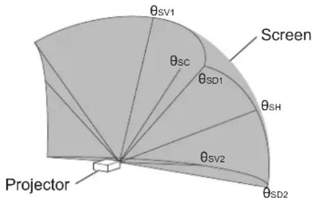
■ Projected angle of view diagram
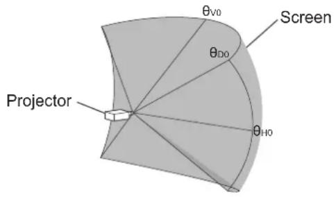
When the lens is centered
When the lens is shifted to the upward Vmax position
| _H0 | Maximum horizontal center angle of view |
| _V0 | Maximum vertical center angle of view |
| _D0 | Maximum diagonal angle of view |
| _SC | Center angle of view |
| _SV1 | Maximum vertical center angle of view |
| _SV2 | Maximum angle of view on opposing side of vertical center ( _SV1 ) |
| _SH | Maximum horizontal center angle of view |
| _SD1 | Maximum diagonal angle of view |
| _SD2 | Maximum angle of view on vertically opposing side of diagonal ( _SD1 ) |
PT-RQ25K / RQ18K / RZ24K / RZ17K / RZ14K
| _H0 | _V0 | _D0 |
| 54.7 34.3 64.5 | ||
| _SC | _SV1 | _SV2 | _SH | _SD1 | _SD2 |
| 22.0 | 56.1 | 12.4 | 59.0 | 78.4 | 56.1 |
PT-RQ22K / RQ13K
| _H0 | _V0 | _D0 |
| 61.3 38.4 72 | 3 |
| _SC | _SV1 | _SV2 | _SH | _SD1 | _SD2 |
| 28.4 | 66.6 | 10.0 | 67.5 | 90.8 | 62.1 |
PT-RZ21K / RZ16K / RZ12K
| _HO | _VO | _DO |
| 65.7 41.1 77.5 |
| _sc | _SV1 | _SV2 | _SH | _SD1 | _SD2 |
| 22.3 | 63.2 | 19.0 | 69.3 | 91.4 | 68.4 |
PT-RS20K / RS11K
| _H0 | _V0 | _D0 |
| 60.7 45.5 75.9 | ||
| _SC | _SV1 | _SV2 | _SH | _SD1 | _SD2 |
| 22.8 | 68.3 | 22.8 | 64.8 | 91.5 | 64.8 |
Note
- The illustrations of projectors in this manual are for informational purposes only and do not represent a specific projector model. Configurations may vary with the model.
● The angle of view values indicated in the tables are lens optical axis angles.
Installation
After checking the height, width, and structure of the installation location while referring to "Standard installation dimensions" on pages 5 to 20, determine the appropriate positions for setting up the screen and installing the projector.
- The [GEOMETRY] function cannot be used when projecting images in the simultaneous format with a PT-RQ22K / RQ13K series DLP™ Projector. When installing the unit on a PT-RQ22K / RQ13K series projector and projecting images in the simultaneous format, obey the following to prevent distortion in the projected image.
- Use a flat screen. - Install the projector so that the front side of the projector is parallel to the screen.
- Install the projector so that the image can be projected within the range of shift adjustment by moving the lens position.
Setting up the screen
Set up the screen according to the specified method in a position which takes into account the projection distance and angle and the type of screen being used.
Screws tightening torques
M6....4±0.5 N·m M10....20±1 N·m
- Use a torque screwdriver or torque wrench to tighten screws and bolts to their specified tightening torques. Do not use electric screwdrivers or impact screwdrivers.
Installing the bracket to the projector
Attach the projector mount bracket to the projector (sold separately).
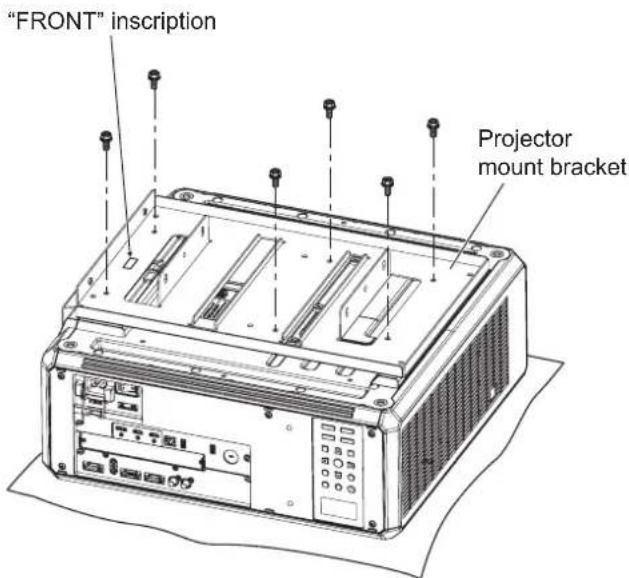
1) Place the projector upside-down onto a piece of soft material.
2) Firmly secure the projector mount bracket to the bottom of the projector using the six supplied captive washer hex head bolts (M6 × 16) as shown in the figure on the left.
Installation (continued)
"FRONT" inscription
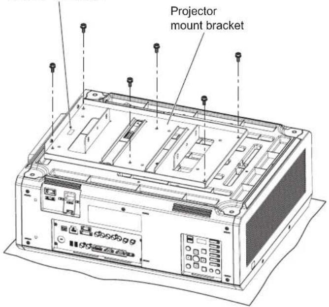
1) Place the projector upside-down onto a piece of soft material.
2) Firmly secure the projector mount bracket to the bottom of the projector using the six supplied captive washer hex head bolts (M6 × 16) as shown in the figure on the left.
Attaching the wire rope to the projector
Attach the drop-prevention wire rope to the projector (sold separately).
Adjustment feet (four)
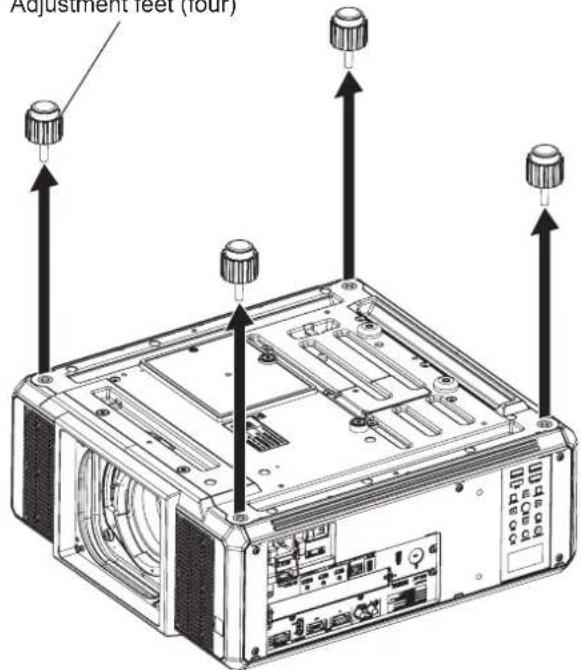
1) Turn the adjustable feet (four) counterclockwise to remove it from the projector.
Attention
● The removed adjustable feet are necessary for floor installations, so be sure to store them safely.
Installation (continued)
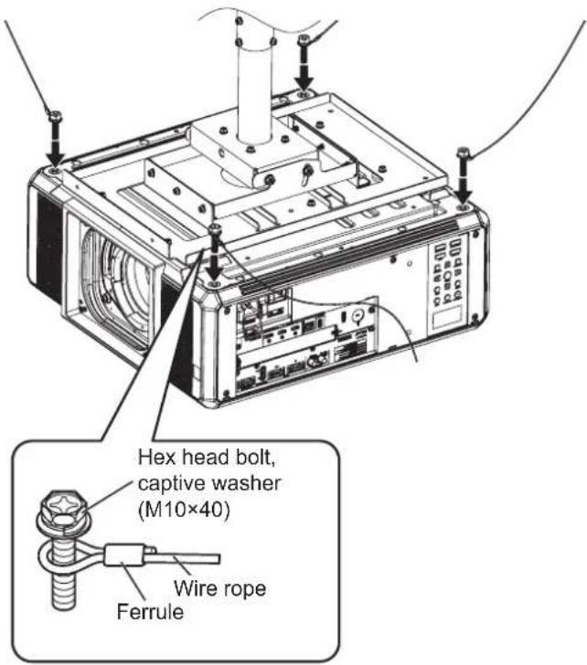
2) As shown in the figure on the left, pass the supplied hex head bolts with washers (M10 × 40) through the rings in the supplied wire rope, and secure the bolts to the threaded holes in which the adjustable feet were previously attached.
Attention
- Be sure to use the supplied hex head bolts with washers and wire rope.
- Secure the supplied hex head bolts with washers (M10 × 40) firmly.
- Stretch the wire ropes with the ferrules pointing toward the outside of the projector.
- For information on how to join this product to the ceiling mount bracket (for high ceilings or for low ceilings) (separately sold) and how to attach the wire rope in the ceiling, refer to the installation instructions or other instructions supplied with the ceiling mount bracket (for high ceilings or for low ceilings).
Note
● The illustration shows an installation using the ET-PKD520H ceiling bracket for high ceilings.
Specifications
| External dimensions | Width: 350 mm (13-25/32") / Height: 52.5 mm (2-1/16") / Depth: 535 mm (21-1/16") |
| Weight Approx. 4.1 kg (9.04 lbs.) | |
Panasonic Connect Co., Ltd.
Web Site : https://panasonic.net/cns/projector/
© Panasonic Connect Co., Ltd. 2022

