
CB1-09HRFN8-I - Air-conditioner MIDEA - Free user manual and instructions
Find the device manual for free CB1-09HRFN8-I MIDEA in PDF.


| Product Type | Split Air Conditioner |
| Brand | Midea |
| Model | CB1-09HRFN8-I |
| Cooling Capacity (BTU/h) | 9,000 |
| Heating Capacity (BTU/h) | 9,000 (Heat Pump Model) |
| Energy Efficiency Ratio (EER) | 12.0 |
| Power Supply | 220-240V ~ 50Hz, 1Ph |
| Current (Cooling) | 4.0 A |
| Power Consumption (Cooling) | 750 W |
| Refrigerant | R32 |
| Indoor Unit Dimensions (WxDxH) | 800 x 225 x 290 mm |
| Outdoor Unit Dimensions (WxDxH) | 720 x 300 x 550 mm |
| Indoor Unit Weight | 10 kg |
| Outdoor Unit Weight | 25 kg |
| Airflow (Hi/Lo) | 400 / 300 m³/h |
| Noise Level (Indoor) | 28-38 dB(A) |
| Noise Level (Outdoor) | 52 dB(A) |
| Operating Temperature Range | -7°C to 43°C |
| Remote Control | Yes (Included) |
| Filter Type | Washable Mesh Filter |
| Cleaning Interval (Filters) | Every 2 weeks |
| Self-Diagnosis | Yes (LED Indicators) |
| Warranty | 5 years (Compressor), 2 years (Parts) |
Frequently Asked Questions - CB1-09HRFN8-I MIDEA
User questions about CB1-09HRFN8-I MIDEA
0 question about this device. Answer the ones you know or ask your own.
Ask a new question about this device
Download the instructions for your Air-conditioner in PDF format for free! Find your manual CB1-09HRFN8-I - MIDEA and take your electronic device back in hand. On this page are published all the documents necessary for the use of your device. CB1-09HRFN8-I by MIDEA.
USER MANUAL CB1-09HRFN8-I MIDEA
natural_image
Pure diagram of a rectangular object with evenly spaced dots and a rounded rectangle at the bottom (no text or symbols)Room Air Conditioner

MSmartHome
Download the app & activate product
USER MANUAL
MODEL NUMBER:
CB1-09HRFN8-I
CB1-12HRFN8-I
CB1-18HRFN8-I
THANK YOU LETTER
Thank you for choosing Midea! Before using your new Midea product, please read this manual thoroughly to ensure that you know how to operate the features and functions that your new appliance offers in a safe way.
CONTENTS
THANK YOU LETTER 01
SAFETY PRECAUTIONS 02
SPECIFICATIONS 06
PRODUCT OVERVIEW 07
PRODUCT INSTALLATION 08
Install Your Indoor Unit 10
Install Your Outdoor Unit 19
Refrigent Piping Connection 23
Air Evacuation 27
Electrical And Gas Leak Checks 29
Test Run 30
Packing And Unpacking The Unit 31
OPERATION INSTRUCTIONS 32
Indoor Unit Display 32
Remote Control Operation 37
App Setup And Operation 48
CARE AND MAINTENANCE 54
TROUBLESHOOTING 56
TRADEMARKS, COPYRIGHTS AND LEGAL STATEMENT 59
DISPOSAL AND RECYCLING 59
DATA PROTECTION NOTICE 60
SAFETY PRECAUTIONS
It's really important you read Safety Precautions Before Operation and Installation Incorrect installation due to ignoring instructions can cause serious damage or injury. The seriousness of potential damage or injuries is classified as either a WARNING or CAUTION.
Explanation of Symbols
 | Warning of electrical voltageThis symbol indicates that there is a danger to life and health of persons due to voltage. |
 | WarningThe signal word indicates a hazard with a medium level of risk which, if not avoided, may result in death or serious injury. |
 | CautionThe signal word indicates a hazard with a low degree of risk which, if not avoided, may result in minor or moderate injury. |
 | AttentionThe signal word indicates important information (e.g. damage to property), but not danger. |
 | Observe instructionsThis symbol indicates that a service technician should only operate and maintain this appliance in accordance with the operating instructions. |
Read these operating instructions carefully and attentively before using/commissioning the unit and keep them in the immediate vicinity of the installation site or unit for later use!

WARNING
This appliance can be used by children aged from 8 years and above and persons with reduced physical, sensory or mental capabilities or lack of experience and knowledge if they have been given supervision or instruction concerning use of the appliance in a safe way and understand the hazards involved. Children shall not play with the appliance. Cleaning and user maintenance shall not be made by children without supervision (European Union countries).
This appliance is not intended for use by persons(including children) with reduced physical, sensory or mental capabilities, or lack of experience and knowledge, unless they have been given supervision or instruction concerning use of the appliance by a person responsible for their safety. Children should be supervised to ensure that they do not play with the appliance.
WARNING FOR PRODUCT USE
- If an abnormal situation arises (like a burning smell), immediately turn off the unit and disconnect the power. Call your dealer for instructions to avoid electric shock, fire or injury.
- Do not insert fingers, rods or other objects into the air inlet or outlet. This may cause injury, since the fan may be rotating at high speeds.
- Do not use flammable sprays such as hair spray, lacquer or paint near the unit. This may cause fire or combustion.
- Do not operate the air conditioner in places near or around combustible gases. Emitted gas may collect around the unit and cause explosion.
- Do not operate your air conditioner in a wet room such as a bathroom or laundry room. Too much exposure to water can cause electrical components to short circuit.
- Do not expose your body directly to cool air for a prolonged period of time.
- Do not allow children to play with the air conditioner. Children must be supervised around the unit at all times.
- If the air conditioner is used together with burners or other heating devices, thoroughly ventilate the room to avoid oxygen deficiency.
- In certain functional environments, such as kitchens, server rooms, etc., the use of specially designed air-conditioning units is highly recommended.
ELECTRICAL WARNINGS
- Only use the specified power cord. If the power cord is damaged, it must be replaced by the manufacturer, its service agent or similarly qualified persons in order to avoid a hazard.
- The product must be properly grounded at the time of installation, or electrical shock may occur.
- For all electrical work, follow all local and national wiring standards, regulations, and the Installation Manual. Connect cables tightly, and clamp them securely to prevent external forces from damaging the terminal. Improper electrical connections can overheat and cause fire, and may also cause shock. All electrical connections must be made according to the Electrical Connection Diagram located on the panels of the indoor and outdoor units.
- All wiring must be properly arranged to ensure that the control board cover can close properly. If the control board cover is not closed properly, it can lead to corrosion and cause the connection points on the terminal to heat up, catch fire, or cause electrical shock.
- Disconnection must be incorporated in the fixed wiring in accordance with the wiring rules.
- Do not pull power cord to unplug unit. Hold the plug firmly and pull it from the outlet. Pulling directly on the cord can damage it, which can lead to fire or electric shock.
- Do not modify the length of the power supply cord or use an extension cord to power the unit.
- Do not share the electrical outlet with other appliances. Improper or insufficient power supply can cause fire or electrical shock.
- Keep power plug clean. Remove any dust or grime that accumulates on or around the plug. Dirty plugs can cause fire or electric shock.
- If connecting power to fixed wiring, an all-pole disconnection device which has at least 3mm clearances in all poles, and have a leakage current that may exceed 10mA, the residual current device(RCD) having a rated residual operating current not exceeding 30mA, and disconnection must be incorporated in the fixed wiring in accordance with the wiring rules.
TAKE NOTE OF FUSE SPECIFICATIONS
The air conditioner's circuit board (PCB) is designed with a fuse to provide overcurrent protection. The specifications of the fuse are printed on the circuit board, such as: T3.15AL/250VAC, T5AL/250VAC, T3.15A/250VAC, T5A/250VAC, T20A/250VAC, T30A/250VAC, etc.
UV-C lamp(Applicable to the unit contains an UV-C lamp only)
This appliance contains a UV-C lamp. Read the maintenance instructions before opening the appliance.
- Do not operate UV-C lamps outside of the appliance.
- Appliances that are obviously damaged must not be operated.
- Unintended use of the appliance or damage to the housing may result in the escape of dangerous UV-C radiation. UV-C radiation may, even in small doses, cause harm to the eyes and skin.
- Before opening doors and access panels bearing the ULTRAVIOLET RADIATION hazard symbol for the conducting USER MAINTENANCE, it is recommended to disconnect the power.
- The UV-C lamp can not be cleaned, repaired and replaced.
- UV-C BARRIERS bearing the ULTRAVIOLET RADIATION hazard symbol should not be removed.

WARNING
This appliance contains an UV emitter. Do not stare at the light source.

WARNINGS FOR PRODUCT INSTALLATION
- Installation must be performed by an authorized dealer or specialist. Defective installation can cause water leakage, electrical shock, or fire.
- Installation must be performed according to the installation instructions. (In North America, installation must be performed in accordance with the requirement of NEC and CEC by authorized personnel only).
Improper installation can cause water leakage, electrical shock, or fire. - Contact an authorized service technician for repair or maintenance of this unit. This appliance shall be installed in accordance with national wiring regulations.
- Only use the included accessories, parts, and specified parts for installation. Using non-standard parts can cause water leakage, electrical shock, fire, and can cause the unit to fail.
- Install the unit in a firm location that can support the unit's weight. If the chosen location cannot support the unit's weight, or the installation is not done properly, the unit may drop and cause serious injury and damage.
- Install drainage piping according to the instructions in this manual. Improper drainage may cause water damage to your home and property.
- For units that have an auxiliary electric heater, do not install the unit within 1 meter (3 feet) of any combustible materials.
- Do not install the unit in a location that may be exposed to combustible gas leaks. If combustible gas accumulates around the unit, it may cause fire.
- Do not turn on the power until all work has been completed.
- When moving or relocating the air conditioner, consult experienced service technicians for disconnection and reinstallation of the unit.
- How to install the appliance to its support, please read the information for details in "indoor unit installation" and "outdoor unit installation" sections.

CAUTION
- Turn off the air conditioner and disconnect the power if you are not going to use it for a long time.
- Turn off and unplug the unit during storms.
- Make sure that water condensation can drain unhindered from the unit.
- Do not operate the air conditioner with wet hands. This may cause electric shock.
- Do not use device for any other purpose than its intended use.
- Do not climb onto or place objects on top of the outdoor unit.
- Do not allow the air conditioner to operate for long periods of time with doors or windows open, or if the humidity is very high.
CLEANING AND MAINTENANCE WARNINGS
- Turn off the device and disconnect the power before cleaning. Failure to do so can cause electrical shock.
- Do not clean the air conditioner with excessive amounts of water.
- Do not clean the air conditioner with combustible cleaning agents. Combustible cleaning agents can cause fire or deformation.
Note about Fluorinated Gasses(Not applicable to the unit using R290 Refrigerant)
- This air-conditioning unit contains fluorinated greenhouse gasses. For specific information on the type of gas and the amount, please refer to the relevant label on the unit itself or the “Owner’s Manual - Product Fiche” in the packaging of the outdoor unit. (European Union products only).
- Installation, service, maintenance and repair of this unit must be performed by a certified technician.
- Product uninstallation and recycling must be performed by a certified technician.
- For equipment that contains fluorinated greenhouse gases in quantities of 5 tonnes of CO2 equivalent or more, but of less than 50 tonnes of CO2 equivalent, If the system has a leak-detection system installed, it must be checked for leaks at least every 24 months.
- When the unit is checked for leaks, proper record-keeping of all checks is strongly recommended.

WARNING FOR USING R32/R290 REFRIGERANT
- When flammable refrigerant are employed, appliance shall be stored in a well-ventilated area where the room size corresponds to the room area as specified for operation.
For R32 frigerant models: - Appliance shall be installed, operated and stored in a room with a floor area larger than 4m^2 .
- For R290 refrigerant models, appliance shall be installed, operated and stored in a
• room with a floor area larger than:
<=2.6kW units: 17.33m ^22.6kW and <=3.5kW units: 25.4m ^2
• >3.5kW and <=5.2kW units: 34.67m ^2
5.3kW and <=7.1kW units: 47.33m ^2
Reusable mechanical connectors and flared joints are not allowed indoors.
SPECIFICATIONS
NOTE ON ILLUSTRATIONS:
Illustrations in this manual are for explanatory purposes. The actual shape of your indoor unit may be slightly different. The actual shape shall prevail.
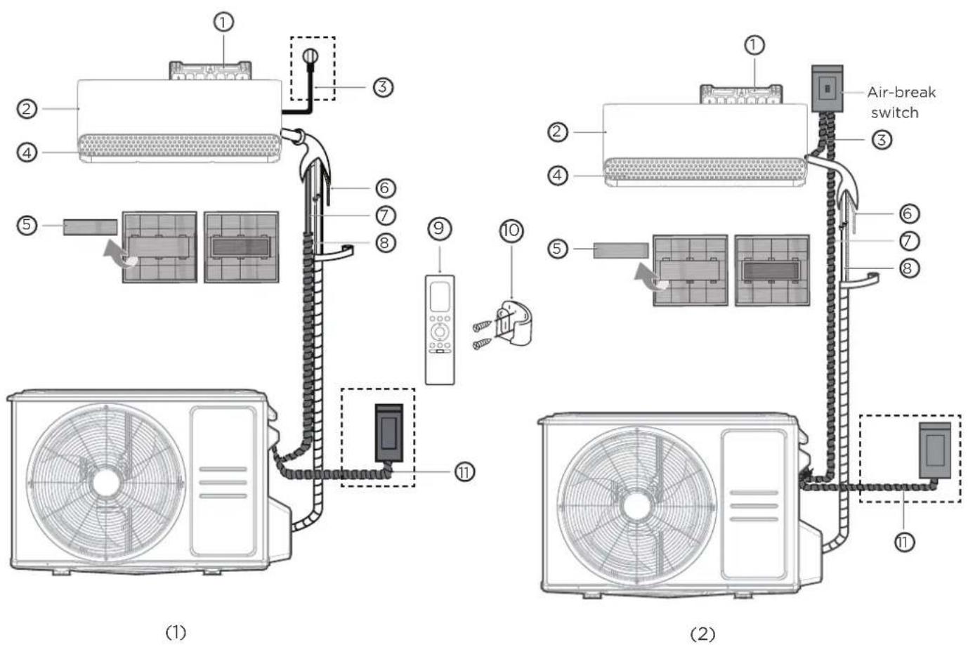
① Wall Mounting Plate
② Front Panel
③ Power Cable(some units)
④ Louver
⑤ Functional Filter (On Back of Main Filter - Some Units)
⑥ Drainage Pipe
⑦ Signal Cable
⑧ Refrigerant Piping
⑨ Remote Controller
⑩ Remote controller Holder (not supplied)
⑪ Outdoor Unit Power Cable (some units)
PRODUCTION INSTALLATION
ACCESSORIES
The air conditioning system comes with the following accessories. Use all of the installation parts and accessories to install the air conditioner. Improper installation may result in water leakage, electrical shock and fire, or cause the equipment to fail. The items are not included with the air conditioner must be purchased separately.
| Name of Accessories Name of AccessoriesQ'ty(pc) Shape Q'ty(pc) Shape | |||||
| Manual | 1-3 |  | Remote controller | 1 | [ATTB] |
| Drain joint (for cooling & heating models) | 1 |  | Battery | 2 |  |
| Seal (for cooling & heating models) | 1 |  | Remote controller holder(purchase separately) | 1 |  |
| Mounting plate | 1 | 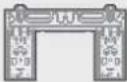 | Fixing screw for remote controller holder(purchase separately) | 2 |  |
| Anchor | 5~8 (depending on models) | 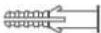 | Small Filter (Need to be installed on the back of main air filter by the authorized technician while installing the machine) | 1-2 (depending on models) | 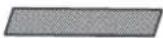 |
| Mounting plate fixing screw | 5~8 (depending on models) |  | |||
Name Shape Quantity(PC)
| Connecting pipe assembly | Liquid side | Φ6.35(1/4in) | Parts you must purc hase separately. Consult the dealer about the proper pipe size of the unit you purchased. |
| Φ9.52(3/8in) | |||
| Gas side | Φ9.52(3/8in) | ||
| Φ12.7(1/2in) | |||
| Φ16(5/8in) | |||
| Φ19(3/4in) | |||
| Magnetic ring and belt(if supplied,please refer to the wiring diagram to install it on the connective cable.) | 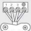  Pass the belt through the hole of the Magnetic ring to fix it on the cable Pass the belt through the hole of the Magnetic ring to fix it on the cable | Varies by model | |
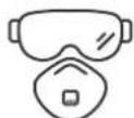
It would be perfect you had these tools
Gloves Screwdriver &
wrench
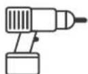
Percussion
drill
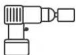
Water drill Goggles & masks Vinyl tape
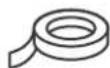
INSTALLATION SUMMARY - INDOOR UNIT
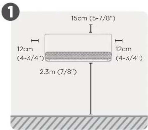
Select Installation Location
natural_image
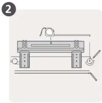
Technical line drawing of a mechanical device with adjustment knobs and a handle (no text or symbols)Attach Mounting Plate
natural_image
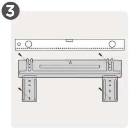
Technical diagram of a mechanical assembly with two plates and a ruler, no visible text or symbolsDetermine Wall Hole Position
natural_image
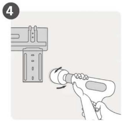
Illustration of a hand using a power tool to adjust a component, with no visible text or symbols.Drill Wall Hole
natural_image
Mechanical diagram showing a tool interacting with a pipe fitting, no text or symbols presentConnect Piping
Connect Wiring
(Not applicable for some locations in North America)
natural_image
Illustration of hands holding a coiled tube with a magnified inset showing the tip (no text or symbols)Prepare Drain Hose
Wrap Piping and Cable
(Not applicable for some locations in North America)
natural_image
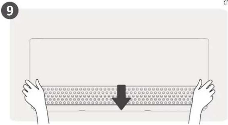
Illustration of two hands holding a rectangular object with a downward arrow, no text or symbols presentMount Indoor Unit
Install You Indoor Unit
Select installation location

NOTE : Prior to installation
Before installing the indoor unit, refer to the label on the product box to make sure that the model number of the indoor unit matches the model number of the outdoor unit.
The following are standards that will help you choose an appropriate location for the unit.
Proper installation locations meet the following standards:
natural_image
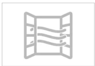
Simple line drawing of a window with horizontal lines inside, no text or symbols present.√ Good air circulation
natural_image
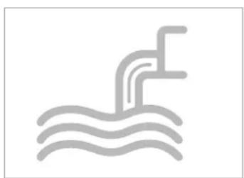
Simple line drawing of a showerhead spraying water, no text or symbols present√ Convenient drainage
natural_image
Gray icon of a person shouting with a megaphone, no text or symbols present√ Noise from the unit will not disturb other people.
natural_image
Abstract gear and chain link icon symbol (no text or labels)√ Firm and solid—the location will not vibrate
☑ Strong enough to support the weight of the unit
DO NOT install unit in the following locations:
∅ Near any source of heat, steam, or combustible gas
∅ Near flammable items such as curtains or clothing

NOTE: FOR PRODUCT INSTALLATION
If there is no fixed refrigerant piping:
While choosing a location, be aware that you should leave ample room for a wall hole (see Drill wall hole for connective piping step) for the signal cable and refrigerant piping that connect the indoor and outdoor units. The default position for all piping is the right side of the indoor unit (while facing the unit). However, the unit can accommodate piping to both the left and right.
√ A location at least one meter from all other electrical devices (e.g., TV, radio, computer)
∅ Near any obstacle that might block air circulation
∅ Near the doorway
∅ In a location subject to direct sunlight
Drill wall hole for connective piping
Determine wall hole location

NOTE : The wall hole size
The size of the wall hole is determined by the connective pipes. When the size of the gas side connective pipe is 16mm(5/8") or more, the wall hole should be 90mm(3-9/16"). For the size of connective pipe is less than 16mm(5/8") , the wall hole should be 65mm(2-1/2").
Step 1:
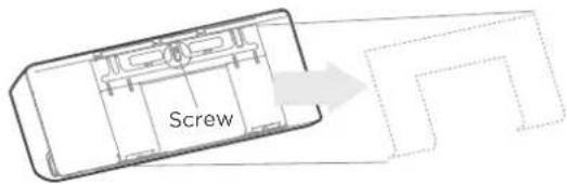
Remove the screw that attaches the mounting plate to the back of the indoor unit.
Step 2:
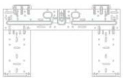
Different models have different mounting plates. For the different customization requirements, the shape of the mounting plate may be slightly different. But the installation dimensions are the same for the same size of indoor unit. See Type A and Type B for example.
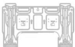
natural_image
Pure electrical circuit lines without any symbolsType A Type B
Step 3:
Secure the mounting plate to the wall with the screws provided. Make sure that mounting plate is flat against the wall.
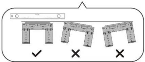
Correct orientation of Mounting Plate
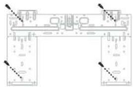
NOTE : FOR CONCRETE OR BRICK WALLS
If the wall is made of brick, concrete, or similar material, drill 5mm-diameter (0.2in-diameter) holes in the wall and insert the sleeve anchors provided. Then secure the mounting plate to the wall by tightening the screws directly into the clip anchors.
Step 4:
Confirm the mounting plate you own. Determine the location of the wall hole based on the position of the mounting plate. The dotted rectangular box above shows the size of your product.
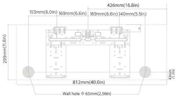
Indoor unit dimensions(WxH): 812mm(40.0in)x299mm(11.8in)

CAUTION
When drilling the wall hole, make sure to avoid wires, plumbing, and other sensitive components.
Drill wall hole
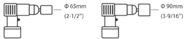
Using a 65mm (2-1/2") or 90mm(3-9/16") core drill(depending on models)
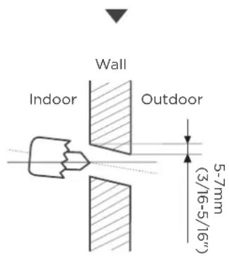
Drill the wall hole
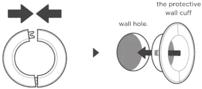
Place the protective wall cuff in the hole.
Step 1:
Using a 65mm (2.5") or 90mm(3.54") core drill(depending on models), drill a hole in the wall. Make sure that the hole is drilled at a slight downward angle, so that the outdoor end of the hole is lower than the indoor end by about 5mm to 7mm (3/16-5/16"). This will ensure proper water drainage.
Step 2:
Place the protective wall cuff in the hole. This protects the edges of the hole and will help seal it when you finish the installation process.
3 Install refrigerant pipe & drain hose

NOTE
The refrigerant piping is inside an insulating sleeve attached to the back of the unit. You must prepare the piping before passing it through the hole in the wall.
Prepare refrigerant piping
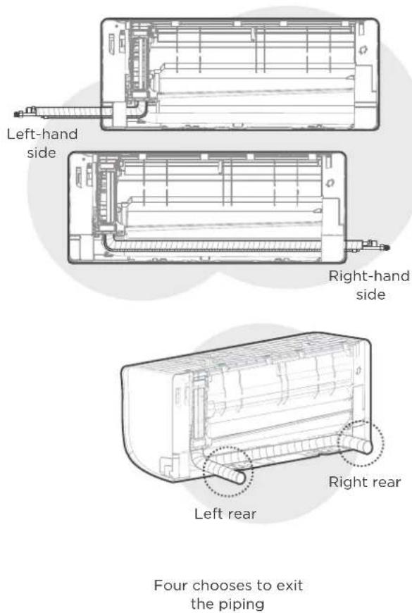
Step 1:
Based on the position of the wall hole relative to the mounting plate, choose the side from which the piping will exit the unit. You have four options for the exit direction of the piping. The description of the piping angle below for details.
Step 2:
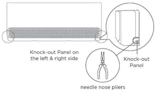
If the wall hole is behind the unit, keep the knock-out panel in place. If the wall hole is to the side of the indoor unit, remove the plastic knock-out panel from that side of the unit. Use needle nose pliers if the plastic panel is too difficult to remove by hand.
Note: Groove has been made in the knock-out panel in order to cut it conveniently. The size of the slot is determined by the diameter of pipings.
Step 3:
connect the indoor unit's refrigerant piping to the connective piping that will join the indoor and outdoor units. Refer to the Refrigerant
Piping Connection section of this manual for detailed instructions.
NOTE: If existing connective piping is already embedded in the wall, proceed directly to the Connect Drain Hose step.

CAUTION
Be extremely careful not to dent or damage the piping while bending them away from the unit. Any dents in the piping will affect the unit's performance.
Step 1:
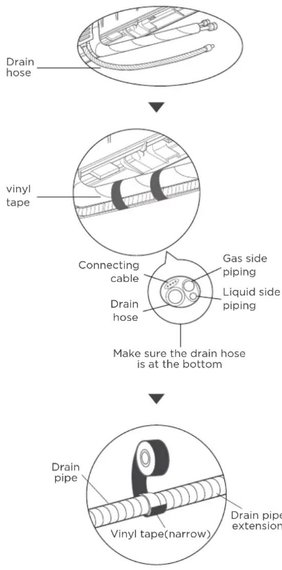
The drain hose can be attached to the left or right side. To ensure proper drainage, attach the drain hose on the same side that your refrigerant piping exits the unit. Attach drain hose extension (purchased separately) to the end of drain hose.
- Wrap the connection point firmly with Teflon tape to ensure a good seal and to prevent leaks.
- For the portion of the drain hose that will remain indoors, wrap it with foam pipe insulation to prevent condensation.
- Remove the air filter and pour a small amount of water into the drain pan to make sure that water flows from the unit smoothly.

NOTE ON DRAIN HOSE PLACEMENT
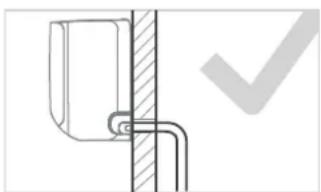
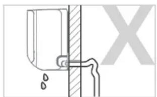
Make sure to arrange the drain hose according to the following figures.
natural_image
Pure mechanical diagram showing a bracket and pipe connection without any text or symbolsCORRECT
Make sure there are no kinks or dent in drain hose to ensure proper drainage.
natural_image
Pure diagram of a pipe joint with a valve and pipe, no text or symbols presentNOT CORRECT
Kinks in the drain hose will create water traps.
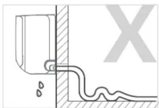
natural_image
Pure diagram of a pipe connection with a wall and ground, no text or symbols presentNOT CORRECT
Kinks in the drain hose will create water traps.
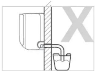
natural_image
Diagram of a pipe system with a bucket and valve, no text or symbols presentNOT CORRECT
Do not place the end of the drain hose in water or in containers that collect water. This will prevent proper drainage.

CAUTION
PLUG THE UNUSED DRAIN HOLE
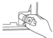
To prevent unwanted leaks you must plug the unused drain hole with the rubber plug provided.

WARNING
- BEFORE PERFORMING ANY ELECTRICAL WORK, READ THESE REGULATIONS
-
BEFORE PERFORMING ANY ELECTRLCAL OR WIRING WORK, TURN OFF THE MAIN POWER TO THE SYSTEM.
-
All wiring must comply with local and national electrical codes, regulations and must be installed by a licensed electrician.
- All electrical connections must be made according to the Electrical Connection Diagram located on the panels of the indoor and outdoor units.
- If there is a serious safety issue with the power supply, stop work immediately. Explain your reasoning to the client, and refuse to install the unit until the safety issue is properly resolved.
- If connecting power to fixed wiring, a switch or circuit breaker that disconnects all poles and has a contact separation of at least 1/8in (3mm) must be incorporated in the fixed wiring. The qualified technician must use an approved circuit breaker or switch.
- Only connect the unit to an individual branch circuit outlet. Do not connect another appliance to that outlet.
- Make sure to properly ground the air conditioner.
- Every wire must be firmly connected. Loose wiring can cause the terminal to overheat, resulting in product malfunction and possible fire.
- Do not let wires touch or rest against refrigerant tubing, the compressor, or any moving parts within the unit.
- To avoid getting an electric shock, never touch the electrical components soon after the power supply has been turned off. After turning off the power, always wait 10 minutes or more before you touch the electrical components.
10 Power voltage should be within 90-110% of rated voltage. Insufficient power supply can cause malfunction, electrical shock, or fire.

WARNING
All wiring must be performed strictly in accordance with the wiring diagram located on the back of the Indoor Unit's front panel.
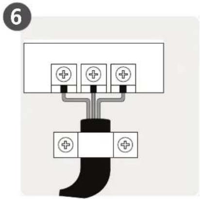
Connect signal and power cables
The signal cable enables communication between the indoor and outdoor units. You must first choose the right cable size before preparing it for connection.
Cable Types(Not applicable for North America)
- Indoor Power Cable (if applicable):
H05VV-F or H05V2V2-F
• Outdoor Power Cable: H07RN-F or H05RN-F
• Signal Cable: H07RN-F
Minimum Cross-Sectional Area of
Power and Signal Cables (For reference)
| Rated Current of Appliance (A) | Nominal Cross-Sectional Area ( mm^2 ) |
| >3 and ≤ 6 | 0.75 |
| >6 and ≤ 10 | 1 |
| >10 and ≤ 16 | 1.5 |
| >16 and ≤ 25 | 2.5 |
| >25 and ≤ 32 | 4 |
| >32 and ≤ 40 | 6 |
CHOOSE THE RIGHT CABLE SIZE
The size of the power supply cable, signal cable, fuse, and switch needed is determined by the maximum current of the unit. The maximum current is indicated on the nameplate located on the side panel of the unit. Refer to this nameplate to choose the right cable, fuse, or switch.
- Open front panel of the indoor unit.
- Using a screwdriver, open the wire box cover on the right side of the unit. This will reveal the terminal block.
-
Unscrew the cable clamp below the terminal block and place it to the side.
-
Facing the back of the unit, remove the plastic panel on the bottom left-hand side.
- Feed the signal wire through this slot, from the back of the unit to the front.
- Facing the front of the unit, connect the wire according to the indoor unit's wiring diagram, connect the u-lug and firmly screw each wire to its corresponding terminal.
- After checking to make sure every connection is secure, use the cable clamp to fasten the signal cable to the unit. Screw the cable clamp down tightly.
- Replace the wire cover on the front of the unit, and the plastic panel on the back.
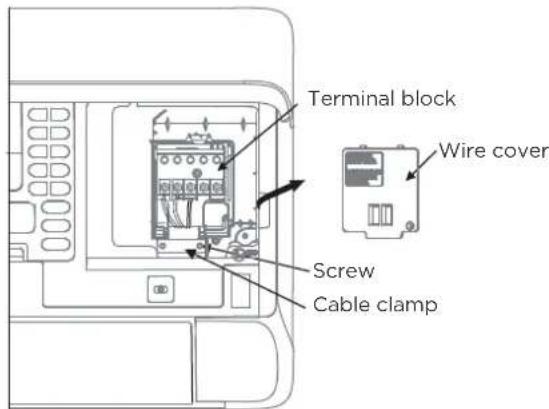
In North America
NOTE: Choose the cable type according to the local electrical codes and regulations. Please choose the right cable size according to the Minimum Circuit Ampacity indicated on the nameplate of the unit.
- Facing the back of the unit, remove the plastic panel on the bottom left-hand side.
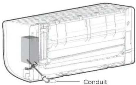
- As shown in the illustration, insert the wires including the ground wire into the conduit and secure them with lock nut onto the conduit mounting plate.
- Match wire colors with terminal numbers on indoor and outdoor unit's terminal blocks and firmly screw wires to the corresponding terminals.
- Connect the ground wires to the corresponding terminals.
- Pull the wires and check that the wires are securely fixed to the terminal block.

DO NOT MIX UP LIVE AND NULL WIRES
This is dangerous, and can cause the air conditioning unit to malfunction.
5
Wrap piping & Cables

NOTE
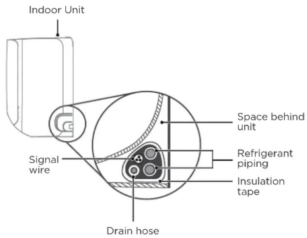
Before passing the piping, and drain hose and the signal cable through the wall hole, you must bundle them together to save space, protect them, and insulate them.
Step 1:
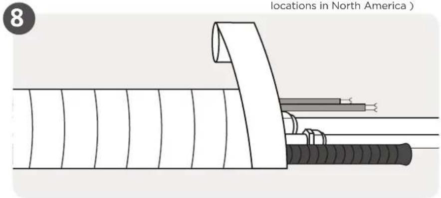
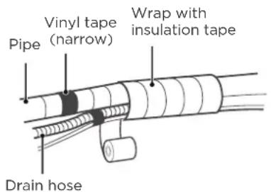
Bundle the drain hose, refrigerant pipes, and signal cable as shown in the figure(Not applicable for some locations in North America).
Step 2:
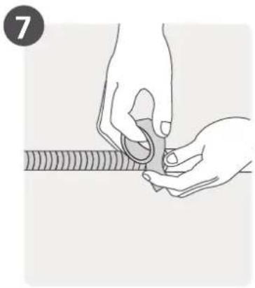
Using adhesive vinyl tape, attach the drain hose to the underside of the refrigerant pipes.
Step 3:
Using insulation tape, wrap the refrigerant pipes, signal wire and drain hose tightly together.
Double-check that all items are bundled.
Do not intertwine signal calbe with other wires
While bundling these items together, do not intertwine or cross the signal cable with any other wiring.
DRAIN HOSE MUST BE ON BOTTOM
Make sure that the drain hose is at the bottom of the bundle. Putting the drain hose at the top of the bundle can cause the drain pan to overflow, which can lead to fire or water damage.
DO NOT WRAP ENDS OF PIPING
When wrapping the bundle, keep the ends of the piping unwrapped. You need to access them to test for leaks at the end of the installation process (refer to Electrical Checks and Leak Checks section of this manual).
6
Mount indoor unit
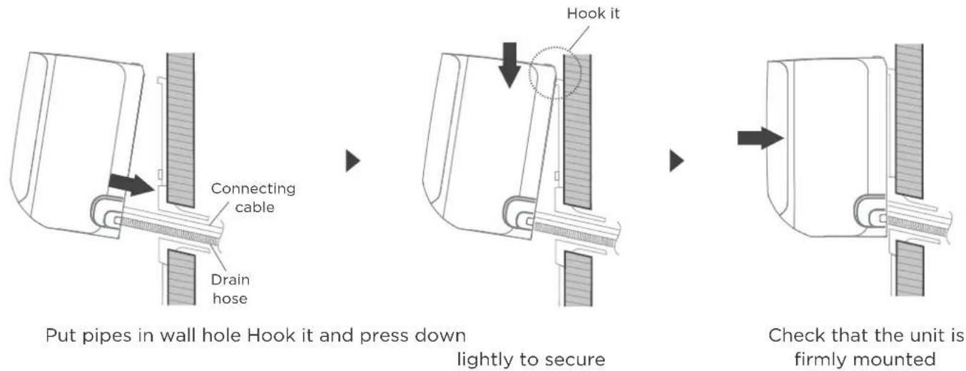
If you installed new connective piping to the outdoor unit, do the following:
• If you have already passed the refrigerant piping through the hole in the wall, proceed to Step 4.
- Otherwise, double-check that the ends of the refrigerant pipes are sealed to prevent dirt or foreign materials from entering the pipes.
- Slowly pass the wrapped bundle of refrigerant pipes, drain hose, and signal wire through the hole in the wall.
- Hook the top of the indoor unit on the upper hook of the mounting plate.
- Check that unit is hooked firmly on mounting by applying slight pressure to the left and right-hand sides of the unit. The unit should not jiggle or shift.
- Using even pressure, push down on the bottom half of the unit. Keep pushing down until the unit snaps onto the hooks along the bottom of the mounting plate.
- Again, check that the unit is firmly mounted by applying slight pressure to the left and the right-hand sides of the unit.
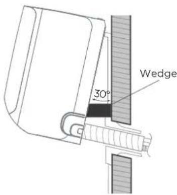
If refrigerant piping is already embedded in the wall, do the following:
- Hook the top of the indoor unit on the upper hook of the mounting plate.
- Use a bracket or wedge to prop up the unit, giving you enough room to connect the refrigerant piping, signal cable, and drain hose.
- Connect drain hose and refrigerant piping (refer to Refrigerant Piping Connection section of this manual for instructions).
- Keep pipe connection point exposed to perform the leak test (refer to Electrical Checks and Leak Checks section of this manual).
• After the leak test, wrap the connection point with insulation tape. - Remove the bracket or wedge that is propping up the unit.
- Using even pressure, push down on the bottom half of the unit. Keep pushing down until the unit snaps onto the hooks along the bottom of the mounting plate.

NOTE : UNIT IS ADJUSTABLE
Keep in mind that the hooks on the mounting plate are smaller than the holes on the back of the unit. If you find that you don't have ample room to connect embedded pipes to the indoor unit, the unit can be adjusted left or right by about 30-50mm (1.18-1.96in), depending on the model.

Move to left or right

CAUTION
For the units adopt the following pipe connectors, please strictly perform the piping work in accordance with the following instructions.
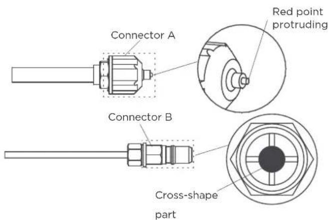
- Before performing the refrigerant piping connection, always wear work gloves and goggles, and remember that the connectors A and B are not allowed to face people directly.
- Keep pressing the cross-shape part of connector B with a tool for about 5\~10 seconds until the red protuding point of connector A retracts completely.
- Remove connectors A and B, then perform the refrigerant piping connection between indoor unit and outdoor unit.
Install Your Outdoor Unit
1 Select installation location

NOTE : PRIOR TO INSTALLATION
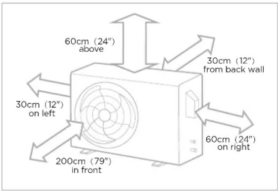
Before installing the outdoor unit, you must choose an appropriate location. The following are standards that will help you choose an appropriate location for the unit.
Proper installation locations meet the following standards:
natural_image
Abstract gray icon of interlocking gears and a chain link (no text or symbols)
√ Noise from the unit will not disturb other people.
√ Good air circulation and ventilation.
Firm and solid—the location can support the unit and will not vibrate.
natural_image
Simple line icons showing sun and water drop symbols (no text or labels)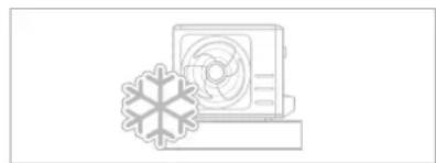
natural_image
Illustration of a wall-mounted air conditioner unit with a snowflake symbol nearby (no text or labels)√ Protected from prolonged periods of direct sunlight or rain.
Where snowfall is anticipated, take appropriate measures to prevent ice buildup and coil damage.
√ Meets all spatial requirements shown in Installation Space Requirements above.

NOTE Install the unit by following local codes and regulations, there may be differ slightly between different regions.

CAUTION:
If the unit is exposed to heavy wind:
Install unit so that air outlet fan is at a 90^ angle to the direction of the wind. If needed, build a barrier in front of the unit to protect it from extremely heavy winds. See Figures below.
If the unit is frequently exposed to heavy rain or snow:
Build a shelter above the unit to protect it from the rain or snow. Be careful not to obstruct air flow around the unit.
If the unit is frequently exposed to salty air(seaside):
Use outdoor unit that is specially designed to resist corrosion.
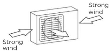
90^ angle to the direction of the wind
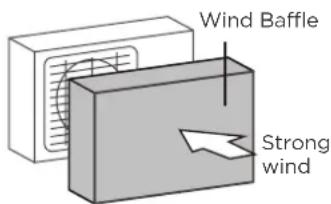
Build a wind Baffle to protect the unit
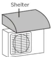
Build a shelter to protect the unit
DO NOT install unit in the following locations:
∅ Near an obstacle that will block air inlets and outlets.
Near a public street, crowded areas, or where noise from the unit will disturb others.
∅ Near animals or plants that will be harmed by hot air discharge.
Near any source of combustible gas.
∅ In a location that is exposed to large amounts of dust
In a location exposed to a excessive amounts of salty air.
Install drain joint(Heat pump unit only)

NOTE : PRIOR TO INSTALLATION
Before bolting the outdoor unit in place, you must install the drain joint at the bottom of the unit. For the units with base pan built-in with multiple holes for proper draining during defrost, the drain joint is no need to be installed.
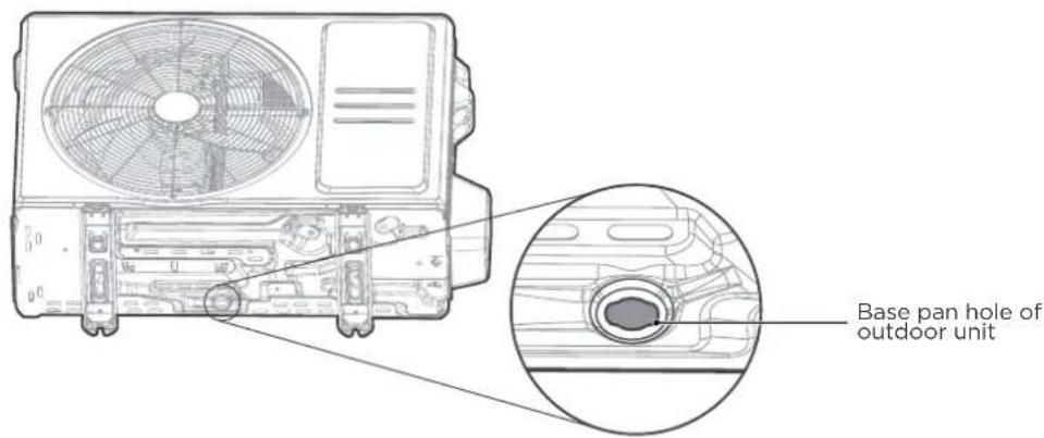
Step 1:
Find out the base pan hole of outdoor unit.
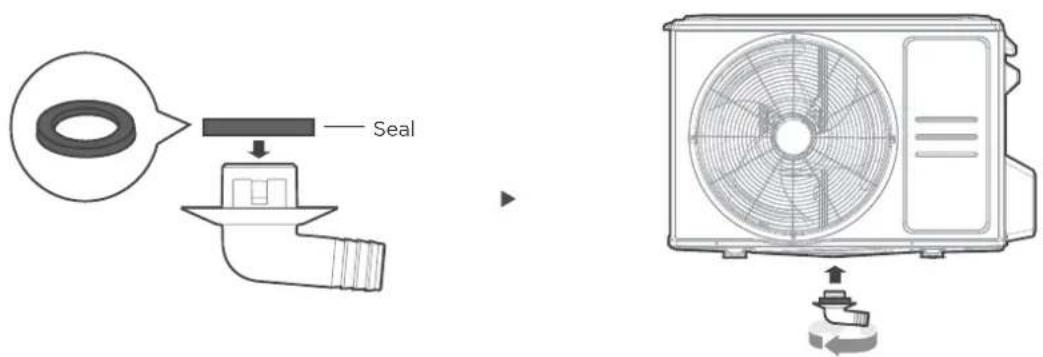
Step 2:
- Fit the rubber seal on the end of the drain joint that will connect to the outdoor unit.
- Insert the drain joint into the hole in the base pan of the unit. The drain joint will click in place.
- Connect a drain hose extension (not included) to the drain joint to redirect water from the unit during heating mode.

NOTE : IN COLD CLIMATES
In cold climates, make sure that the drain hose is as vertical as possible to ensure swift water drainage. If water drains too slowly, it can freeze in the hose and flood the unit.
3
Anchor Outdoor Unit

WARNING
WHEN DRILLING INTO CONCRETE, EYE PROTECTION IS RECOMMENDED AT ALL TIME.
- The outdoor unit can be anchored to the ground or to a wall-mounted bracket with bolt(M10). Prepare the installation base of the unit according to the dimensions below.
- The following is a list of different outdoor unit sizes and the distance between their mounting feet. Prepare the installation base of the unit according to the dimensions below.
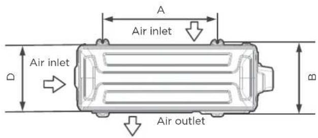
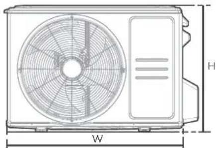
natural_image
Technical line drawing of a front-end air conditioner fan with labeled dimensions (W and H), no text or symbols present.Top view Front view
| Outdoor Unit Dimensions (mm)W x H x D | Mounting Dimensions | |
| Distance A (mm) | Distance B (mm) | |
| 680x542x248 (26.8"x 21.3"x 9.8") 452 (17.8") 230 (9.1") | ||
| 720x495x270 (28.3"x 19.5"x 10.6") 452 (17.8") 255 (10.0") | ||
| 765x555x303 (30.1"x 21.8"x 11.9") 452 (17.8") 286(11.3") | ||
| 805x554x330 (31.7"x 21.8"x 12.9") 511 (20.1") 317 (12.5") | ||
| 890x673x342 (35.0"x 26.5"x 13.5") | 663 (26.1") | 354 (13.9") |
| 946x810x420 (37.2"x 31.9"x 16.5") | 673 (26.5") | 403 (15.9") |
| 946x810x410 (37.2"x 31.9"x 16.1") 673 (26.5") 403 (15.9") | ||
If you will install the unit on the ground or on a concrete mounting platform, do the following:
- Mark the positions for four expansion bolts based on dimensions chart.
• Pre-drill holes for expansion bolts. - Place a nut on the end of each expansion bolt.
- Hammer expansion bolts into the pre-drilled holes.
- Remove the nuts from expansion bolts, and place outdoor unit on bolts.
- Put washer on each expansion bolt, the replace the nuts.
• Using a wrench, tighten each nut until snug.
If you will install the unit on a wall-mounted bracket, do the following:
- Mark the position of bracket holes based on dimensions chart.
• Pre-drill the holes for the expansion bolts. - Place a washer and nut on the end of each expansion bolt.
- Thread expansion bolts through holes in mounting brackets, put mounting brackets in position, and hammer expansion bolts into the wall.
- Check that the mounting brackets are level.
- Carefully lift unit and place its mounting feet on brackets.
- Bolt the unit firmly to the brackets.
- If allowed, install the unit with rubber gaskets to reduce vibrations and noise.

CAUTION
Make sure that the wall is made of solid brick, concrete, or of similarly strong material. The wall must be able to support at least four times the weight of the unit.
4
Connect signal and power cables

WARNING - Before the Operation
- ALL WIRING WORK MUST BE PERFORMED STRICTLY IN ACCORDANCE WITH THE WIRING DIAGRAM LOCATED INSIDE OF WIRE COVER OF THE OUTDOOR UNIT.
- BEFORE PERFORMING ANY ELECTRICAL OR WIRING WORK, TURN OFF THE MAIN POWER TO THE SYSTEM.
Prepare the cable for connection
Please choose the right cable according to the "Cable types" in page 24.
- Using wire strippers, strip the rubber jacket from both ends of cable to reveal about 40mm (1.57in) of the wires inside.
- Strip the insulation from the ends of the wires.
- Using a wire crimper, crimp u-lugs on the ends of the wires.
Pay attention to live wire
While crimping wires, make sure you clearly distinguish the Live ("L") Wire from other wires.
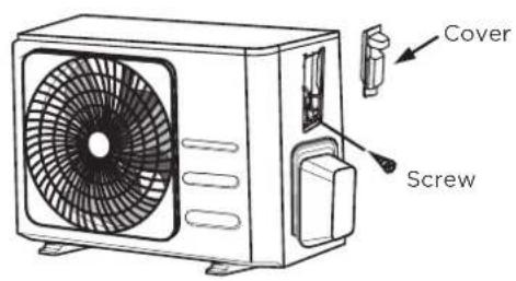
The outside unit's terminal block is protected by an electrical wiring cover on the side of the unit. A comprehensive wiring diagram is printed on the inside of the wiring cover.
- Unscrew the electrical wiring cover and remove it.
- Unscrew the cable clamp below the terminal block and place it to the side.
- Connect the wire according to the wiring diagram, and firmly screw the u-lug of each wire to its corresponding terminal.
- After checking to make sure every connection is secure, loop the wires around to prevent rain water from flowing into the terminal.
- Using the cable clamp, fasten the cable to the unit. Screw the cable clamp down tightly.
• Insulate unused wires with PVC electrical tape. Arrange them so that they do not touch any electrical or metal parts. - Replace the wire cover on the side of the unit, and screw it in place.
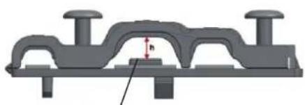
NOTE: If the cable clamp looks like the following, please select the appropriate through-hole according to the diameter of the wire.
Choose the right cable size
The size of the power supply cable, signal cable, fuse, and switch needed is determined by the maximum current of the unit. The maximum current is indicated on the nameplate located on the side panel of the unit.
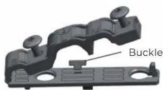
natural_image
3D mechanical component labeled 'Buckle' showing a bracket and mounting holes (no other text or symbols)Three size hole: Small, Large, Medium
natural_image
3D mechanical component diagram showing a bracket with mounting flanges and a central housing (no text or symbols)When the calbe is not fasten enough, use the buckle to prop it up, so it can be clamped tightly.
In North America
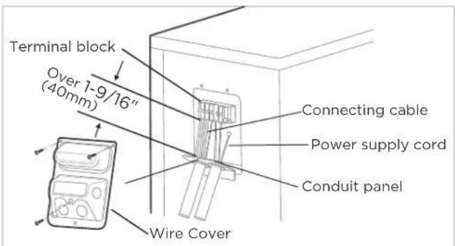
The outside unit's terminal block is protected by an electrical wiring cover on the side of the unit. A comprehensive wiring diagram is sticked on the inside of the wiring cover.
- Remove the wire cover from the unit by loosening the 3 screws.
- Dismount caps on the conduit panel.
- Temporarily mount the conduit tubes (not included) on the conduit panel.
- Properly connect both the power supply and low voltage lines to the corresponding terminals on the terminal block.
- Ground the unit in accordance with local codes.
- Be sure to size each wire allowing several inches longer than the required length for wiring.
- Use lock nuts to secure the conduit tubes.
NOTE: Please choose the right cable size according to the Minimum Circuit Ampacity indicated on the nameplate of the unit.
Please select the appropriate through-hole according to the diameter of the wire.
How to properly connect the wire lines.
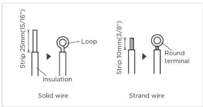
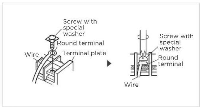
Step 2: Step 1:
The treatment about the end of the wire. connecting the line to the corresponding terminals on the terminal block.
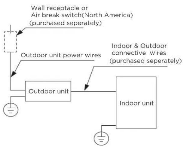
flowchart
graph TD
    A["Outdoor unit"] --> B["Indoor unit"]
    B --> C["Indoor & Outdoor connective wires (purchased separately)"]
    D["Wall receptacle or Air break switch(North America) (purchased separately)"] --> A
    E["Outdoor unit power wires"] --> A
    F["Ground"] --> A
(A)
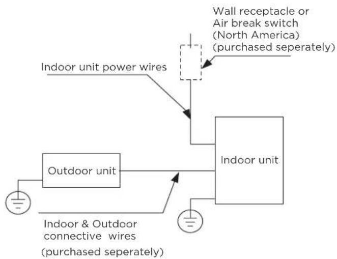
flowchart
graph TD
    A["Indoor unit"] --> B["Indoor unit power wires"]
    A --> C["Indoor unit"]
    D["Indoor & Outdoor connective wires (purchased separately)"] --> C
    E["Wall receptacle or Air break switch (North America) (purchased separately)"] --> C
(B)
1
Piping Connection Precautions

WARNING
WHEN CONNECTING REFRIGERANT PIPING, DO NOT LET SUBSTANCES OR GASES OTHER THAN THE SPECIFIED REFRIGERANT ENTER THE UNIT. THE PRESENCE OF OTHER GASES OR SUBSTANCES WILL LOWER THE UNIT'S CAPACITY, AND CAN CAUSE ABNORMALLY HIGH PRESSURE IN THE REFRIGERATION CYCLE. THIS CAN CAUSE EXPLOSION AND INJURY.
Note on Pipe Length
The length of refrigerant piping will affect the performance and energy efficiency of the unit. Nominal efficiency is tested on units with a pipe length of 5 meters (16.5ft). A minimum pipe run of 3 metres is required to minimise vibration & excessive noise. Connection Instructions - Refrigerant Piping.
Maximum Length and Drop Height of Refrigerant Piping per Unit Model
| Model | Capacity (BTU/h) | Max. Length (m) | Max. Drop Height (m) |
| R410A,R32 Inverter Split Air Conditioner | < 15,000 | 25 (82ft) 10 (33ft) | |
| ≥ 15,000 and < 24,000 | 30 (98.5ft) | 20 (66ft) | |
| ≥ 24,000 and < 36,000 | 50 (164ft) 25 (82ft) | ||
| ≥ 36,000 and < 60,000 | 65 (213ft) 30 (98.5ft) | ||
| R22 Fixed-speed Split Air Conditioner | < 18,000 | 10 (33ft) 5 (16ft) | |
| ≥ 18,000 and < 21,000 | 15 (49ft) | 8(26ft) | |
| ≥ 21,000 and < 35,000 | 20 (66ft) | 10(33ft) | |
| ≥ 35,000 and < 41,000 | 10 (33ft)25 (82ft) | ||
| R410A, R32 Fixed-speed Split Air Conditioner | 20 (66ft) | 8(26ft)< 18,000 | |
| ≥ 18,000 and < 36,000 | 25 (82ft) | 10(33ft) | |
| ≥ 36,000 and < 60,000 | 30 (98.5ft) | 15 (49ft) |
Connection Instructions – Refrigerant Piping
Step 1: Cut pipes
When preparing refrigerant pipes, take extra care to cut and flare them properly. This will ensure efficient operation and minimize the need for future maintenance.
• Measure the distance between the indoor and outdoor units.
- Using a pipe cutter, cut the pipe a little longer than the measured distance.
- Make sure that the pipe is cut at a perfect 90^ angle.
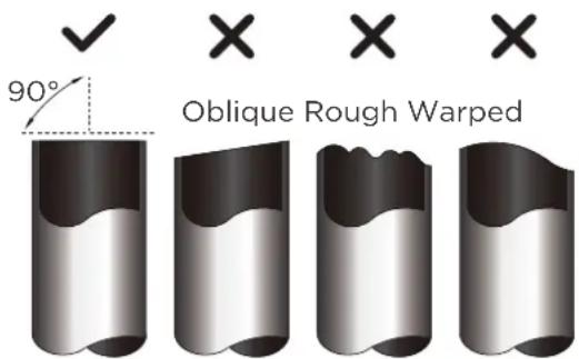

DO NOT DEFORM PIPE WHILE CUTTING
Be extra careful not to damage, dent, or deform the pipe while cutting. This will drastically reduce the heating efficiency of the unit.
MUST BE CHECK OVER THE END OF THE PIPE FOR CRACKS AND EVEN FLARING. ENSURE THE PIPE IS SEALED.
Step 2: Remove burrs
Burrs can affect the air-tight seal of refrigerant piping connection. They must be completely removed.
- Hold the pipe at a downward angle to prevent burrs from falling into the pipe.
- Using a reamer or deburring tool, remove all burrs from the cut section of the pipe.
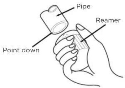
Step 3: Flare pipe ends
Proper flaring is essential to achieve an airtight seal.
• After removing burrs from cut pipe, seal the ends with PVC tape to prevent foreign materials from entering the pipe.
• Sheath the pipe with insulating material.
- Place flare nuts on both ends of pipe. Make sure they are facing in the right direction, because you can't put them on or change their direction after flaring.
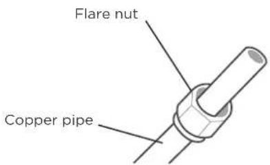
- Remove PVC tape from ends of pipe when ready to perform flaring work.
- Clamp flare form on the end of the pipe. The end of the pipe must extend beyond the edge of the flare form in accordance with the dimensions shown in the table below.
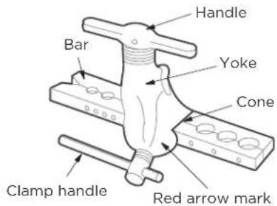
PIPING EXTENSION BEYOND FLARE FORM
| Outer Diameter of Pipe (mm) | A (mm) | |
| Min. Max. | ||
| ∅ 6.35 (∅ 1/4") | 0.7 (0.0275") 1.3 | (0.05") |
| ∅ 9.52 (∅ 3/8") | 1.0 (0.04") | 1.6 (0.063") |
| ∅12.7 (∅ 1/2") 1.0 (0.04") | 1.8 (0.07") | |
| ∅ 16 (∅ 5/8") | 2.0 (0.078") 2.2 | (0.086") |
| ∅ 19 (∅ 3/4") | 2.0 (0.078") 2.4 | (0.094") |
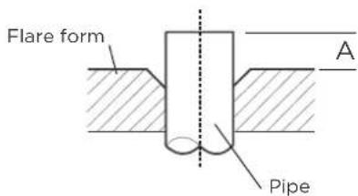
- Place flaring tool onto the form.
- Turn the handle of the flaring tool clockwise until the pipe is fully flared.
- Remove the flaring tool and flare form, then inspect the end of the pipe for cracks and even flaring.
2 Refer to Torque Requirement to connect pipes

CAUTION
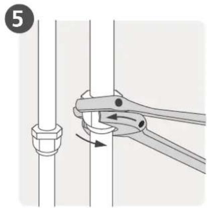
WHEN CONNECTING REFRIGERANT PIPES, BE CAREFUL NOT TO USE EXCESSIVE TORQUE OR TO DEFORM THE PIPING IN ANY WAY. YOU SHOULD FIRST CONNECT THE LOW-PRESSURE PIPE, THEN THE HIGH-PRESSURE PIPE.
MINIMUM BEND RADIUS
When bending connective refrigerant piping, the minimum bending radius is 10cm.
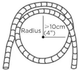
Instructions for Connecting Piping to Indoor Unit
Step 1: Step 2:
- Align the center of the two pipes that you will connect.
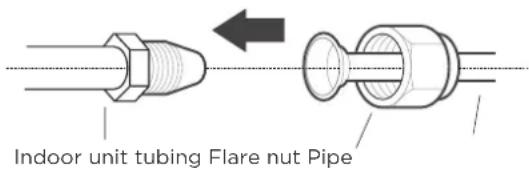
- Tighten the flare nut as tightly as possible by hand.
• Using a spanner, grip the nut on the unit tubing. - While firmly gripping the nut on the unit tubing, use a torque wrench to tighten the flare nut according to the torque values in the Torque Requirements table below. Loosen the flaring nut slightly, then tighten again.
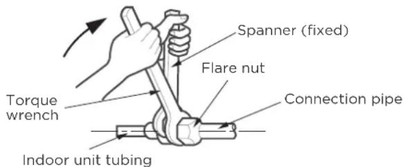
TORQUE REQUIREMENTS
| Outer Diameter of Pipe(mm) | Tightening Torque(N•m) | Flare dimension(B)(mm) | Flare shape |
| ∅ 6.35 (∅ 1/4") 8.4-8.7 (0.33-0.34"20(180-200kgf.cm) | 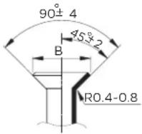 | ||
| ∅ 9.52 (∅ 3/8") | 32-39(320-390kgf.cm) | 13.2-13.5 (0.52-0.53") | |
| ∅ 12.7 (∅ 1/2") | 49-59(490-590kgf.cm) | 16.2-16.5 (0.64-0.65") | |
| ∅ 16 (∅ 5/8") | 57-71(570-710kgf.cm) | 19.2-19.7 (0.76-0.78") | |
| ∅ 19 (∅ 3/4") | 67-101(670-1010kgf.cm) | 23.2-23.7 (0.91-0.93") |

DO NOT USE EXCESSIVE TORQUE
Excessive force can break the nut or damage the refrigerant piping. You must not exceed torque requirements shown in the table above.
3
Connecting Piping to Outdoor Unit

NOTE
This section still needs to be operated according to the TORQUE REQUIREMENTS chart on the previous page.
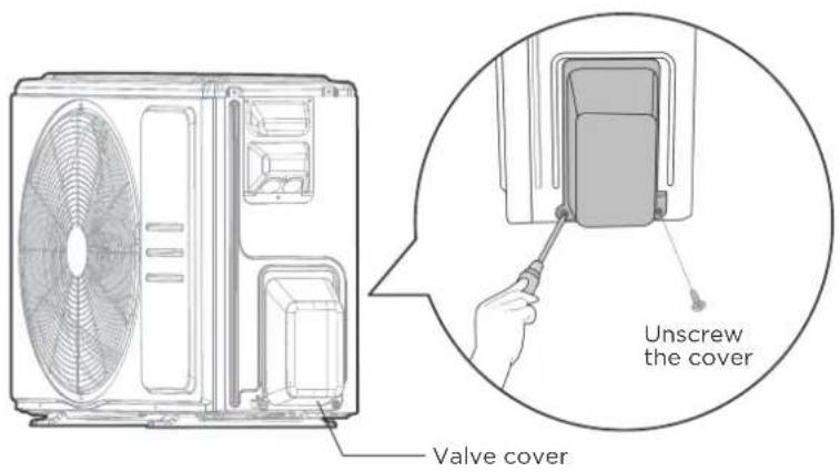
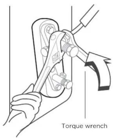
Step 1:
- Unscrew the cover from the packed valve on the side of the outdoor unit.
Step 2:
- Remove protective caps from ends of valves.
- Align flared pipe end with each valve, and tighten the flare nut as tightly as possible by hand.
- Using a spanner, grip the body of the valve. Do not grip the nut that seals the service valve.

USE SPANNER TO GRIP MAIN BODY OF VALVE
Torque from tightening the flare nut can snap off other parts of valve.
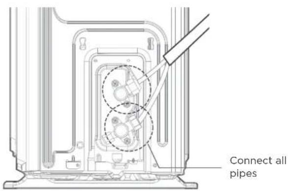
Step 3:
- While firmly gripping the body of the valve, use a torque wrench to tighten the flare nut according to the correct torque values.
- Loosen the flaring nut slightly, then tighten again.
- Repeat Steps 1 to 3 for the remaining pipe.
Air Evacuation

NOTE : PREPARATIONS AND PRECAUTIONS
Air and foreign matter in the refrigerant circuit can cause abnormal rises in pressure, which can damage the air conditioner, reduce its efficiency, and cause injury. Use a vacuum pump and manifold gauge to evacuate the refrigerant circuit, removing any non-condensable gas and moisture from the system. Evacuation should be performed upon initial installation and when unit is relocated.

BEFORE PERFORMING EVACUATION
√ Make sure the connective pipes between the indoor and outdoor units are connected properly.
√ Check to make sure all wiring is connected properly.
Evacuation Instructions
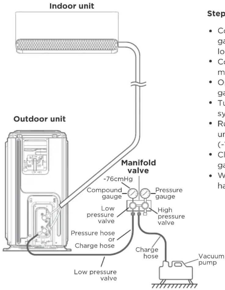
Step 1:
- Connect the charge hose of the manifold gauge to service port on the outdoor unit's low pressure valve.
- Connect another charge hose from the manifold gauge to the vacuum pump.
- Open the Low Pressure side of the manifold gauge. Keep the High Pressure side closed.
- Turn on the vacuum pump to evacuate the system.
- Run the vacuum for at least 15 minutes, or until the Compound Meter reads -76cmHG (-10 Pa).
- Close the Low Pressure side of the manifold gauge, and turn off the vacuum pump.
- Wait for 5 minutes, then check that there has been no change in system pressure.
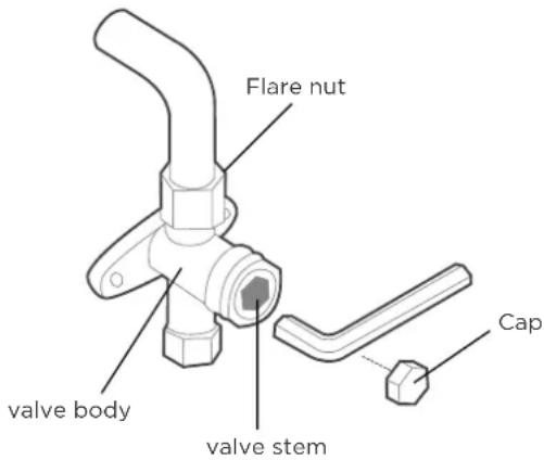
Step 2:
- If there is a change in system pressure, refer to Gas Leak Check section for information on how to check for leaks. If there is no change in system pressure, unscrew the cap
- from the packed valve (high pressure valve). Insert hexagonal wrench into the packed valve (high pressure valve) and open the valve by turning the wrench in a 1/4 counterclockwise turn. Listen for gas to exit the system, then close the valve after 5 seconds.
- Watch the Pressure Gauge for one minute to make sure that there is no change in pressure. The Pressure Gauge should read slightly higher than atmospheric pressure.
- Remove the charge hose from the service port.
- Using hexagonal wrench, fully open both the high pressure and low pressure valves.
- Tighten valve caps on all three valves (service port, high pressure, low pressure) by hand. You may tighten it further using a torque wrench if needed.

OPEN VALVE STEMS GENTLY
When opening valve stems, turn the hexagonal wrench until it hits against the stopper. Do not try to force the valve to open further.

NOTE ON ADDING REFRIGERANT
Some systems require additional charging depending on pipe lengths. The standard pipe length varies according to local regulations. For example, in North America, the standard pipe length is 7.5m (25'). In other areas, the standard pipe length is 5m (16'). The refrigerant should be charged from the service port on the outdoor unit's low pressure valve. The additional refrigerant to be charged can be calculated using the following formula:
ADDITIONAL REFRIGERANT PER PIPE LENGTH
| Connective Pipe Length (m) | Air Purging Method | Additional Refrigerant | |
| ≤ Standard pipe length | Vacuum Pump N/A | ||
| > Standard pipe length | Vacuum Pump | Liquid Side: ∅ 6.35 (1/4")R410A:(Pipe length - standard length) x 15g/m(Pipe length - standard length) x 0.16oZ/ftR32:(Pipe length - standard length) x 12g/m(Pipe length - standard length) x 0.13oZ/ftR22:(Pipe length - standard length) x 20g/m(Pipe length - standard length) x 0.21oZ/ft | Liquid Side: ∅ 9.52 (3/8")R410A:(Pipe length - standard length) x 30g/m(Pipe length - standard length) x 0.32oZ/ftR32:(Pipe length - standard length) x 24g/m(Pipe length - standard length) x 0.26oZ/ftR22:(Pipe length - standard length) x 40g/m(Pipe length - standard length) x 0.42oZ/ft |

DO NOT MIX REFRIGERANT TYPES.
Electrical And Gas Leak Checks

WARNING - RISK OF ELECTRIC SHOCK
ALL WIRING MUST COMPLY WITH LOCAL AND NATIONAL ELECTRICAL CODES, AND MUST BE INSTALLED BY A LICENSED ELECTRICIAN.

BEFORE TEST RUN
Only perform test run after you have completed the following steps:
- Electrical Safety Checks – Confirm that the unit's electrical system is safe and operating properly
- Gas Leak Checks – Check all flare nut connections and confirm that the system is not leaking
- Confirm that gas and liquid (high and low pressure) valves are fully open
Electrical Safety Checks
After installation, confirm that all electrical wiring is installed in accordance with local and national regulations, and according to the Installation Manual.
BEFORE TEST RUN
Check Grounding Work
Measure grounding resistance by visual detection and with grounding resistance tester.
DURING TEST RUN
Check for Electrical Leakage
During the Test Run, use an electroprobe and multimeter to perform a comprehensive electrical leakage test.
If electrical leakage is detected, turn off the unit immediately and call a licensed electrician to find and resolve the cause of the leakage.
Note: This may not be required for some locations in North America.
Gas Leak Checks
There are two different methods to check for gas leaks.
Soap and Water Method
Using a soft brush, apply soapy water or liquid detergent to all pipe connection points on the indoor unit and outdoor unit. The presence of bubbles indicates a leak.
Leak Detector Method
If using leak detector, refer to the device's operation manual for proper usage instructions.
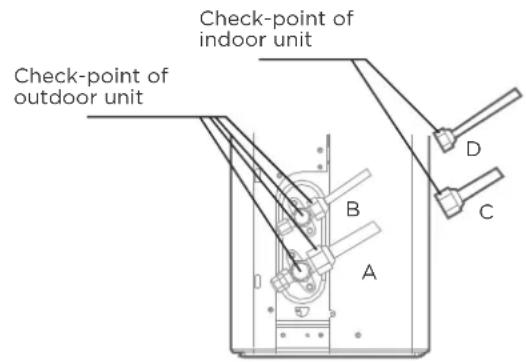
A: Low pressure stop valve
B: High pressure stop valve
C& D: Indoor unit flare nuts
AFTER PERFORMING GAS LEAK CHECKS
After confirming that the all pipe connection points DO NOT leak, replace the valve cover on the outside unit.
Test Run
Test Run Instructions
You should perform the Test Run for at least 30 minutes.
- Connect power to the unit.
- Press the ON/OFF button on the remote controller to turn it on.
- Press the MODE button to scroll through the following functions, one at a time:
• COOL-Select lowest possible temperature
• HEAT-Select highest possible temperature - Let each function run for 5 minutes, and perform the following checks:
| List of Checks to Perform | PASS/FAIL | |
| No electrical leakage | ||
| Unit is properly grounded | ||
| All electrical terminals properly covered | ||
| Indoor and outdoor units are solidly installed | ||
| All pipe connection points do not leak | Outdoor (2): | Indoor (2): |
| Water drains properly from drain hose | ||
| All piping is properly insulated | ||
| Unit performs COOL function properly | ||
| Unit performs HEAT function properly | ||
| Indoor unit louvers rotate properly | ||
| Indoor unit responds to remote controller | ||
DOUBLE-CHECK PIPE CONNECTIONS
During operation, the pressure of the refrigerant circuit will increase. This may reveal leaks that were not present during your initial leak check. Take time during the Test Run to double-check that all refrigerant pipe connection points do not have leaks. Refer to Gas Leak Check section for instructions.
• After the Test Run is successfully completed, and you confirm that all checks points in List of Checks to Perform have PASSED, do the following:
a. Using remote control, return unit to normal operating temperature.
b. Using insulation tape, wrap the indoor refrigerant pipe connections that you left uncovered during the indoor unit installation process.
IF AMBIENT TEMPERATURE IS BELOW 16°C(60°F)
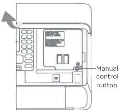
You can't use the remote controller to turn on the COOL function when the ambient temperature is below 16°C/62°F. In this instance, you can use the MANUAL CONTROL button to test the COOL function.
- Lift the front panel of the indoor unit, and raise it until it clicks in place.
- The MANUAL CONTROL button is located on the right-hand side of the unit. Press it 2 times to select the COOL function.
• Perform Test Run as normal.
Packing And Unpacking The Unit
Instructions for packing and unpacking the unit:
Unpacking:
Indoor unit:
- Cut the sealing tape on the carton with a knife, one cut on the left, one cut in the middle and one cut on the right.
- Use the vice to take out the sealing nails on the top of the carton.
3.Open the carton. - Take out the middle support plate if it is included.
- Take out the accessory package, and take out the connecting wire if it is included.
- Lift the machine out of the carton and lay it flat.
- Remove the left and right package foam or the upper and lower packaging foam, untie the packaging bag.
Outdoor Unit
- Cut the packing belt.
- Take the unit out of the carton.
- Remove the foam from the unit.
- Remove the packaging bag from the unit.
Packing:
Indoor unit:
- Put the indoor unit into the packing bag.
- Attach the left and right package foam or the upper and lower packaging foam to the unit.
- Put the unit into the carton, then put accessory package in.
- Close the carton and seal it with the tape.
- Using the packing belt if necessary.
Outdoor unit:
- Put the outdoor unit into the packing bag.
- Put the bottom foam into the box.
- Put the unit into the carton, then put the upper packaging foam on the unit.
- Close the carton and seal it with the tape.
- Using the packing belt if necessary.
NOTE: Please keep all packaging items if you may need in the future.
OPERATION INSTRUCTIONS

NOTE
- Different models have different front panel and display window. Not all the indicators describing below are available for the air conditioner you purchased. Please check the indoor display window of the unit you purchased.
- Illustrations in this manual are for explanatory purposes. The actual shape of your indoor unit may be slightly different. The actual shape shall prevail.
Indoor Unit Display
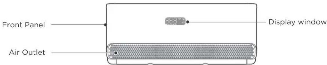

| Display Code Meanings Display Code | |
| 888 | Displays temperature, operation feature and Error codes. |
| When Wireless Control feature is activated. | |
| When Air magic or UV lamp(if any) feature is activated. | |
| ECO | When ECO feature is activated. |
| ON(for 3s when) | TIMER ON is set (if the unit is OFF, “ON” remains on when TIMER ON is set).UV lamp, Fresh, Brezzeless, SWING, TURBO, or SILENCE features is turned on. |
| OF(for 3s when) | TIMER OFF is set.UV lamp, Fresh, Brezzeless, SWING, TURBO, or SILENCE features is turned off. |
| dF | When defrosting(cooling & heating units). |
| DL | When active clean function is turned on. |
| FP | When 8°C(46°F) heating mode is turned on. |
Operating Temperature
When your air conditioner is used outside of the following temperature ranges, certain safety protection features may activate and cause the unit to disable.
Inverter Split Type
| COOL Mode | HEAT Mode | DRY Mode | |
| Room Temp. | 16°C~32°C(60°F~90°F) 0°C~30°C(32°F~86°F) | 10°C~32°C(50°F~90°F) | |
| Outdoor Temp. | 0°C~50°C(32°F~122°F) | ||
| -15°C~50°C(5°F~122°F) -15°C~24°C(5°F~75°F) 0°C~50°C(32°F~122°F)For models withlow temp. cooling systems. | |||
| -15°C~50°C(5°F~122°F) -15°C~24°C(5°F~75°F)For special tropical models | 0°C~52°C(32°F~126°F)For special tropical models | ||
FOR OUTDOOR UNITS WITH AUXILIARY ELECTRIC HEATER
When outside temperature is below 0^ C ( 32^ F), we strongly recommend keeping the unit plugged in at all time to ensure smooth ongoing performance.
Fixed-speed Type
| COOL Mode HEAT Mode | DRY Mode | ||
| Room Temp. | 16°C~32°C (60°F~90°F) 0°C~30°C (32°F~86°F) | 10°C~32°C(50°F~90°F) | |
| Outdoor Temp. | 18°C~43°C (64°F~109°F) | 11°C~43°C (52°F~109°F) | |
| -7°C~43°C (19°F~109°F) -7°C~24°C(19°F~75°F) 18°C~43°C (64°F~109°F)For models with low-temp cooling systems | |||
| 18°C~52°C (64°F~126°F) -15°C~24°C(5°F~75°F)For special tropical models | 18°C~52°C (64°F~126°F)For special tropical models | ||
NOTE: Room relative humidity less than 80%. If the air conditioner operates in excess of this figure, the surface of the air conditioner may attract condensation. Please sets the vertical air flow louver to its maximum angle (vertically to the floor), and set HIGH fan mode.
To further optimize the performance of your unit, do the following:
- Keep doors and windows closed.
- Limit energy usage by using TIMER ON and TIMER OFF functions.
- Do not block air inlets or outlets.
- Regularly inspect and clean air filters.
More features
- Auto-Restart
If the unit loses power, it will automatically restart with the prior settings once power has been restored.
• Anti-mildew(some units)
When turning off the unit from COOL, AUTO (COOL), or DRY modes, the air conditioner will continue operate at very low power to dry up condensed water and prevent mildew growth.
• Wireless Control (Model dependent)
Wireless control allows you to control your air conditioner using your mobile phone and a wireless connection.
For the USB device access, replacement, maintenance operations must be carried out by professional staff.
• Active Clean function(some units)
-- The Active Clean Technology washes away dust when it adheres to the heat exchanger by automatically freezing and then rapidly thawing the frost. A “pi-pi” sound will be heard. The Active clean operation is used to produce more condensed water to improve the cleaning effect, and the cold air will blow out. After cleaning, the internal wind wheel then keeps operating with hot air to blow-dry the evaporator, thus keeping the inside clean.
-- When this function is turned on, the indoor unit display window appears "CL", after 20 to 130 minutes, the unit will turn off automatically and cancel Active Clean function.
-- For some units, the system will start high-temperature cleaning process, and the temperature of air outlet is very high. Please keep away from it. And this would lead to the rising of the room temperature.
- Louver Angle Memory
When turning on your unit, the louver will automatically resume its former angle.
• Air Magic+ function(some units)
Under the effect of electric field generated by outer double-tube emitter, millions of negative ions are formed as Super Negative Ion Shockwave to eradicate bacteria and viruses in wider extent.
- Coolflash function
Cool Flash technology can drive your whole room to the instant cool. With large air volume and long airflow, the temperature of the whole room can be reduced in a short time.
- Heatflash function
With fast and strong heating airflow, the Heat Flash technology can warm up your whole room in a short time.
• Refrigerant Leakage Detection
The indoor unit will automatically display "ELOC" when it detects refrigerant leakage.
• UV-C lamp function(some units)
When the UV lamp function is initiated, the UV lamp emit UV-C radiation to help to purify the air inside.
- Breezeless function
- The revolutionary double deflectors can bend, veer and soften the airflow to provide multiple levels of softness as you demand.
- Enjoy the cozy coolness with breeze billowing away from you, with mild breeze, or eventually without a noticeable breeze.
- The deflector consist of thousands of mini-holes can transform the strong airflow into thousands of tiny strings of air that gives you softest touch of cooling.
- Breezeless Operation
The air conditioner will adjust the louver angle and fan speed automatically on the basis of room temperature and humidity variable. There are four different operation state, See Fig. 1, Fig. 2, Fig. 3, Fig. 4.
Breeze billowing away
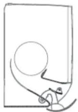
Mild breeze
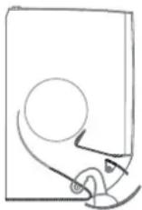
Fig. 1 Fig. 2
Breezeless
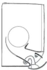
Breezeless
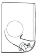
Fig. 3 Fig. 4
NOTE: For the rooms with large heat load or the outdoor temperature is too high, you'd better not choose breezeless operation, this may result in uncomfortable feeling.
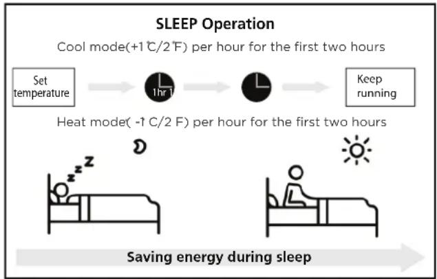
- Sleep Operation
The SLEEP function is used to decrease energy use while you sleep (and don't need the same temperature settings to stay comfortable).
Press the SLEEP button on remote control when in COOL mode, the unit will increase the temperature by 1^ C ( 2^ F) after 1 hour, and will increase an additional 1^ C ( 2^ F) after another hour.
When in HEAT mode, the unit will decrease the temperature by 1^ C ( 2^ F) after 1 hour, and will decrease an additional 1^ C ( 2^ F) after another hour.
The sleep feature will stop after 8 hours and the system will keep running with final situation.
flowchart
graph LR
    A["Set temperature"] --> B["1hr 1"]
    B --> C[" "]
    C --> D["Keep running"]
    E["Heat mode (-1 C/2 F) per hour for the first two hours"] --> F[" "]
    G["Saving energy during sleep"] --> H[" "]
Setting Angle of Air Flow

NOTE : Setting angle of air flow(Remote control)
While the unit is on, use the SWING button on remote control to set the direction (vertical/horizontal angle) of airflow. Please refer to the Remote Control operation for details.
NOTE ON LOUVER ANGLES
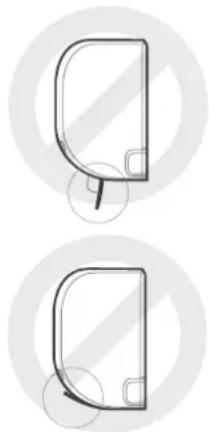
- Do not set louver at too vertical an angle for long periods of time. When using COOL or DRY mode. It would be condense the water on the louver blade, which will drop on your floor or furnishings.
- Setting the louver at too small an angle when using COOL or HEAT mode, can reduce the performance of the AC due to restricted air flow.
natural_image
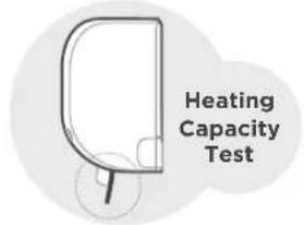
Two identical line drawings of a curved mechanical part with circular cutouts, no text or symbols present.- According to the relative standards requirement, please sets the vertical air flow louver to its maximum angle under heating capacity test.

NOTE
Do not move louver by hand. This will cause the louver to become out of sync. If this occurs, turn off the unit and unplug it for a few seconds, then restart the unit. This will reset the louver.

CAUTION
Do not put your fingers in or near the blower and suction side of the unit. The high-speed fan inside the unit may cause injury.
Manual Operation(without remote)

CAUTION: For product use
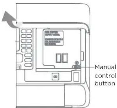
The manual button is intended for testing purposes and emergency operation only. Please do not use this function unless the remote control is lost and it is absolutely necessary. To restore regular operation, use the remote control to activate the unit. Unit must be turned off before manua operation.
To operate your unit manually:
- Open the front panel of the indoor unit.
- Locate the MANUAL CONTROL button on the right-hand side of the unit.
- Press the MANUAL CONTROL button one time to activate FORCED AUTO mode.
- Press the MANUAL CONTROL button again to activate FORCED COOLING mode.
- Press the MANUAL CONTROL button a third time to turn the unit off.
- Close the front panel.
Remote Control Operation
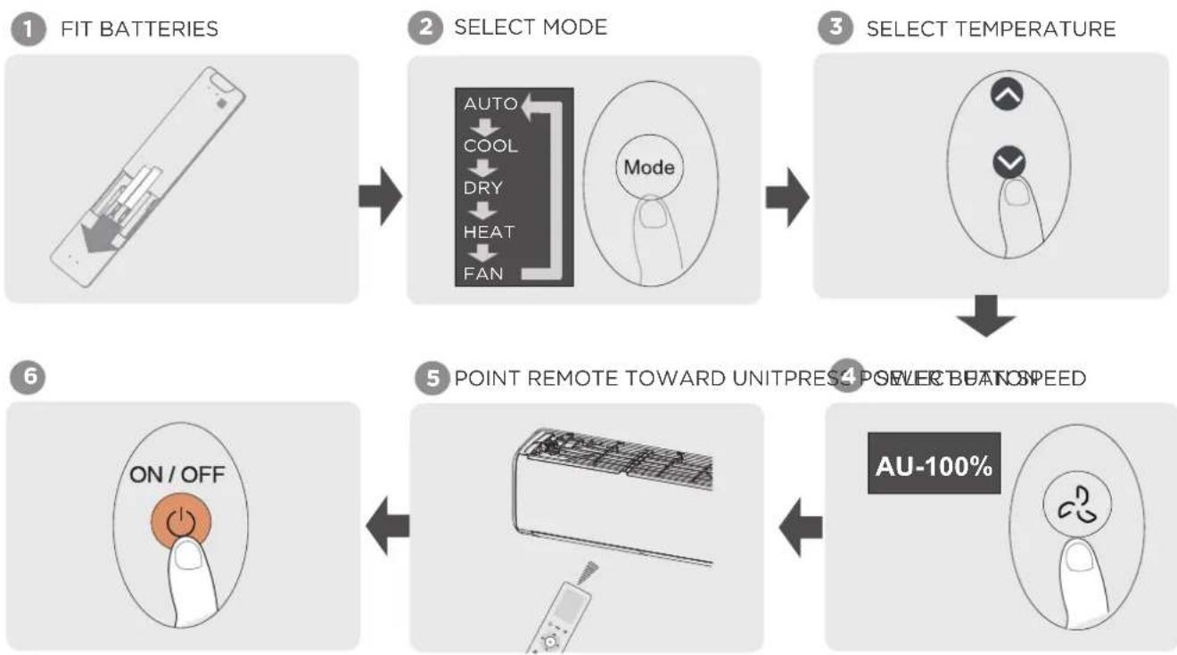
Quick Start Guide
NOT SURE WHAT A FUNCTION DOES?
Refer to the How to Use Basic Functions and How to Use Advanced Functions sections of this manual for a detailed description of how to use your air conditioner.
SPECIAL NOTE
- Button designs on your unit may differ slightly from the example shown.
- If the indoor unit does not have a particular function, pressing that function's button on the remote control will have no effect.
Handling the Remote Controller
Inserting and Replacing Batteries
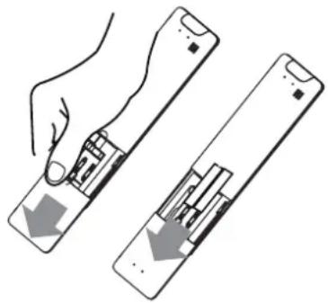
Your air conditioning unit may come with two batteries(some units). Put the batteries in the remote control before use.
- Slide the back cover from the remote control downward, exposing the battery compartment.
- Insert the batteries, paying attention to match up the (+) and (-) ends of the batteries with
- the symbols inside the battery compartment. Slide the battery cover back into place.
natural_image
Illustration of a hand holding a remote control panel with two arrows indicating movement or change (no text or symbols present)
BATTERY NOTES
For optimum product performance:
- Do not mix old and new batteries, or batteries of different types.
- Do not leave batteries in the remote control if you don't plan on using the device for more than 2 months.

BATTERY DISPOSAL
Do not dispose of batteries as unsorted municipal waste. Refer to local laws for proper disposal of batteries.
TIPS FOR USING REMOTE CONTROL
- The remote control must be used within 8 meters of the unit.
- The unit will beep when remote signal is received.
- Curtains, other materials and direct sunlight can interfere with the infrared signal receiver.
- Remove batteries if the remote will not be used more than 2 months.
NOTES FOR USING REMOTE CONTROL
The device could comply with the local national regulations.
- In Canada, it should comply with CAN ICES-3(B)/NMB-3(B).
- In USA, this device complies with part 15 of the FCC Rules. Operation is subject to the following two conditions:
(1) This device may not cause harmful interference, and
(2) this device must accept any interference received, including interference that may cause undesired operation.
This equipment has been tested and found to comply with the limits for a Class B digital device, pursuant to part 15 of the FCC Rules. These limits are designed to provide reasonable protection against harmful interference in a residential installation. This equipment generates, uses and can radiate radio frequency energy and, if not installed and used in accordance with the instructions, may cause harmful interference to radio communications. However, there is no guarantee that interference will not occur in a particular installation. If this equipment does cause harmful interference to radio or television reception, which can be determined by turning the equipment off and on, the user is encouraged to try to correct the interference by one or more of the following measures:
- Reorient or relocate the receiving antenna.
- Increase the separation between the equipment and receiver.
- Connect the equipment into an outlet on a circuit different from that to which the receiver is connected.
- Consult the dealer or an experienced radio/TV technician for help.
- Changes or modifications not approved by the party responsible for compliance could void user's authority to operate the equipment.
Buttons and Functions
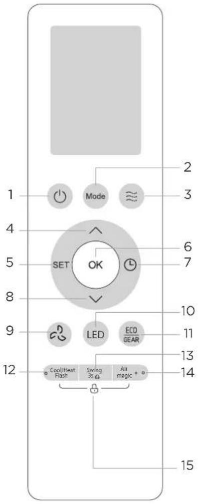
Model A
| Description | ||
| No.1 |  | ON/OFFTurn the unit on or off. |
| No.2 |  | MODEAuto > Cool > Dry > Heat > FanNOTE:HEAT mode is not supported by the cooling only appliance. |
| No.3 |  | BREEZEBreezeless > Breeze away > Breeze mild>Stop |
| No.4 |  | TEMP.Increases temperature in 0.5°C (1°F) increments. Max.temperature is 30°C (86°F).(Press together ∧ & √ buttons at the same time for 3 seconds will alternate the temperature display between the °C & °F). |
| No.5 |  | SETActive clean>Sleep > Follow Me > AP mode > Active clean |
| No.6 |  | OKUsed to confirm the selected functions |
| No.7 | L | TEMP.Set timer to turn unit on or off |
| No.8 |  | TEMP.Decreases temperature in 0.5°C (1°F) increments. Min.temperature is 16°C (60°F) |
| No.9 |  | FAN SPEEDAU > 20% > 40% > 60% > 80% > 100%Press the TEMP ∧ or √ button to increase/ decrease the fan speed in 1% increments. |
| No.10 |  | LEDTurns LED display & air conditioner buzzer on and off |
| No.11 | ECO/GEARECOGEAR | ECO/GEARECO > GEAR(75%) > GEAR(50%) > Previous setting mode > ECO |
| No.12 |  | Cool/Heat FlashReduce(cool mode) or rise(heat mode) temperature in a short time. |
| No.13 |  | SWINGStarts and stops the horizontal louver movement. Hold down for 3 seconds to initiate vertical louver auto swing feature(some units). |
| No.14 |  | Air magic+Used to start/stop the Air magic and UV-C lamp (if any) function. |
| No.15 | Cool/Heat Flash  | Air magic +LOCKPress together these two buttons simultaneously for 5 seconds to lock the keyboard. Press together these two buttons for 2 seconds to unlock the keyboard. |
Buttons and Functions
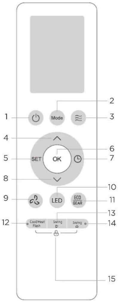
Model B
| Description | ||
| No.1 |  | ON/OFFTurn the unit on or off. |
| No.2 |  | MODEAuto > Cool > Dry > Heat > FanNOTE:HEAT mode is not supported by the cooling only appliance. |
| No.3 | [TYSK] | BREEZEBreezeless > Breeze away > Breeze mild>Stop |
| No.4 |  | TEMP.Increases temperature in 0.5°C (1°F) increments. Max.temperature is 30°C (86°F).(Press together ∧ & √ buttons at the same time for 3 seconds will alternate the temperature display between the °C & °F). |
| No.5 |  --- --- | SETActive clean > Sleep > Follow Me > AP mode* > Active clean[*]: Model dependent |
| No.6 |  | OKUsed to confirm the selected functions |
| No.7 |  | TEMP.Set timer to turn unit on or off |
| No.8 | | TEMP.Decreases temperature in 0.5°C (1°F) increments. Min.temperature is 16°C (60°F) |
| No.9 |  | FAN SPEEDAU > 20% >40% >60% > 80% > 100%Press the TEMP ∧ or √ button to increase/ decrease the fan speed in 1% increments. |
| No.10 |  | LEDTurns LED display & air conditioner buzzer on and off |
| No.11 |  ECO/GEARECO GEAR ECO/GEARECO GEAR | ECO/GEARECO > GEAR(75%) > GEAR(50%) > Previous setting mode > ECO |
| No.12 |  | Cool/Heat FlashReduce(cool mode) or rise(heat mode) temperature in a short time. |
| No.13 |  | SWING(up and down)Starts and stops the horizontal louver movement. Hold down for 2 seconds to initiate horizontal louver auto swing feature(some units). |
| No.14 |  | SWING(left and right)Starts and stops the vertical louver movement. |
| No.15 | Cool/Heat Flash  | Swing △LOCKPress together these two buttons simultaneously for 5 seconds to lock the keyboard. Press together these two buttons for 2 seconds to unlock the keyboard. |
Buttons and Functions
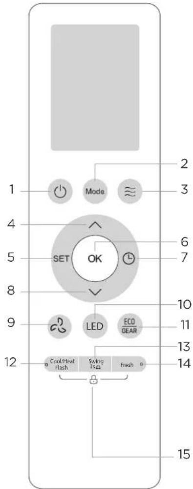
Model C
| Description | ||
| No.1 | [2736] | ON/OFFTurn the unit on or off. |
| No.2 | [6WBT] | MODEAuto > Cool > Dry > Heat > FanNOTE:HEAT mode is not supported by the cooling only appliance. |
| No.3 |  | BREEZEBreezeless > Breeze away > Breeze mild>Stop |
| No.4 |  | TEMP.Increases temperature in 0.5°C (1°F) increments. Max.temperature is 30°C (86°F).(Press together & buttons at the same time for 3 seconds will alternate the temperature display between the °C & °F). |
| No.5 |  | SETActive clean >Sleep > Follow Me > AP mode*> Active clean[*]: Model dependent |
| No.6 |  | OKUsed to confirm the selected functions |
| No.7 |  | TEMP.Set timer to turn unit on or off |
| No.8 |  | TEMP.Decreases temperature in 0.5°C (1°F) increments. Min.temperature is 16°C (60°F) |
| No.9 | | FAN SPEEDAU > 20% >40% > 60% > 80% > 100%Press the TEMP or button to increase/ decrease the fan speed in 1% increments. |
| No.10 |  | LEDTurns LED display & air conditioner buzzer on and off |
| No.11 |  | ECO/GEARECO > GEAR(75%) > GEAR(50%) > Previous setting mode > ECO |
| No.12 | Cool/Heat[Cool/Heat-Cool/Heat-Cool/Heat-Cool/Heat-Cool/Heat-Cool/Heat-Cool/Heat-Cool/Heat-Cool/Heat-Cool/Heat-Cool/Heat-Cool/Heat-Cool/Heat-Cool/Heat-Cool/Heat-Cool/Heat-Cool/Heat-Cool/Heat-Cool/Heat-Cool/Heat-Cool/Heat-Cool/Heat-Cool/Heat-Cool/Heat-Cool/Heat-Cool/Heat- | |
| No.13 |  | SWINGStarts and stops the horizontal louver movement. Hold down for 3 seconds to initiate vertical louver auto swing feature(some units). |
| No.14 |  | FRESHStarts and stops the UV lamp function. |
| No.15 | Cool/Heat[CDT] [WDT22] | FreshLOCKPress together these two buttons simultaneously for 5 seconds to lock the keyboard. Press together these two buttons for 2 seconds to unlock the keyboard. |
Remote Screen Indicators
Information are displayed when the remote controller is power up.
![Wind flow follow people* Breeze Away Breeze mild Breezeless Intelligent eye* Low battery (If flashes) [*]: Not available for this unit. Active clean Not available for this unit. Sleep mode Follow me Air magic+ mode* Wireless control* [*]: Model dependent MODE display Displays the current mode AUTO COOL DRY HEAT FAN Transmission Indicator ECO Feature GEAR Feature Timer ON Timer OFF Lock Feature Slience Feature Temperature/Timer/Fan speed display Displays the set temperature by default, or fan speed or timer setting when using TIMER ON/OFF functions. FAN SPEED SLIENCE LOW MED HIGHAUTO 1% 2-20% 21-40% 41-60% 61-80% 81-100% NOTE: The fan speed can not be adjusted in AUTO or DRY mode. Not available for this unit Horizontal louver swing Vertical louver auto swing → → → → → → → → → → → → → → → → → → → → → → → → → → → → → → → → → → → → → → → → → → → → → → → → → → → → → → → → → → → → → → → → → → → → → → → → → → → → → → → → → → → → → → → → → → → → → → → → → → → → → ←→ ←→ ←→ ←→ ←→ ←→ ←→ ←→ ←→ ←→ ←→ ←→ ←→ ←→ ←→ ←→ ←→ ←→ ←→ ←→ ←→ ←→ ←→ ←→ ←→ ←→ ←→ ←→ ←→ ←→ ←→ ←→ ←→ ←→ ←→ ←→ ←→ ←→ ←→ ←→ ←→ ←→ ←→ ←→ ←→ ←→ ←→ ←→ ←→ ←→ ← → ←→ ←→ ←→ ←→ ←→ ←→ ←→ ←→ ←→ ←→ ←→ ←→ ←→ ←→ ←→ ←→ ←→ ←→ ←→ ←→ ←→ ←→ ←→ ←→ ←→ ←→ ←→ ←→ ←→ ←→ ←→ ←→ ←→ ←→ ←→ ←→ ←→ ←→ ←→ ←→ ←→ ←→ ←→ ←→ ←→ ←→ ←→ ←→ ←→ <-————————————————————————————————————————————————————————————————————————————————————————————————————————————————————————————————————————————————————————————————————————————————————————————————————————————————————————————————————————————————————————————————————————————————————————————————————————————————-----------------------------](/content/2026/05/856153/images/2e6481fc1bfc13a9bafe312c29963df4b7fb18d0883f14467b55f1e1ec7b6f37.jpg)

NOTE
- All indicators shown in the figure are for the purpose of clear presentation. But during the actual operation, only the relative function signs are shown on the display window.
How to Use Basic Functions

NOTE
Before operation, please ensure the unit is plugged in and power is available.
AUTO Mode
Select AUTO mode Set your desired temperature


Turn on the air conditioner
NOTE:
- In AUTO mode, the unit will automatically select the COOL, FAN, or HEAT function based on the set temperature.
- In AUTO mode, fan speed can not be set.
COOL or HEAT Mode
Select COOL/HEAT mode

Set the temperature


Set the fan speed

Turn on the air conditioner
DRY Mode
Select DRY mode Set your desired temperature Turn on the air conditioner


NOTE: In DRY mode, fan speed can not be set since it has already been automatically controlled.
FAN Mode
Select FAN mode Turn on the set condition speed


NOTE: In FAN mode, you can't set the temperature. As a result, no temperature displays in remote screen.
Setting the TIMER
TIMER ON/OFF - Set the amount of time after which the unit will automatically turn on/off.
TIMER ON setting
Press TIMER button to initiate the ON time sequence.
Press Temp. up or down button for for multiple times to set the desired time to turn on the unit.
Point remote to unit and wait 1sec, the TIMER ON will be activated.


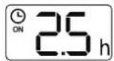

TIMER OFF setting
Press TIMER button to initiate the OFF time sequence.
Press Temp. up or down button for for multiple times to set the desired time to turn off the unit.
Point remote to unit and wait 1sec, the TIMER OFF will be activated.


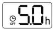

NOTE:
- When setting the TIMER ON or TIMER OFF, the time will increase by 30 minutes increments with each press, up to 10 hours. After 10 hours and up to 24, it will increase in 1 hour increments. (For example, press 5 times to get 2.5h, and press 10 times to get 5h,) The timer will revert to 0.0 after 24.
- Cancel either function by setting its timer to 0.0h.
TIMER ON & OFF setting(example)
Keep in mind that the time periods you set for both functions refer to hours after the current time.

flowchart
graph LR
    A["Clock with xn"] --> B["Analog Display with ON 2.5 h"]
    B --> C["Digital Display with LCD screen"]
    C --> D["Digital Display with Time/Duration 5.0 h"]
    D --> E["Display with 1 sec"]
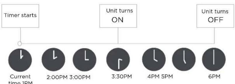
flowchart
graph TD
    A["Timer starts"] --> B["Current time 1PM"]
    B --> C["2:00PM 3:00PM"]
    C --> D["3:30PM"]
    D --> E["4PM 5PM"]
    E --> F["6PM"]
    G["Unit turns ON"] --> D
    H["Unit turns OFF"] --> F
Example: If current timer is 1:00PM, to set the timer as above steps, the unit will turn on 2.5h later (3:30PM) and turn off at 6:00PM.

How to Use Advanced Functions
Swing function
Press Swing button Set airflow direction
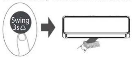
The horizontal louver will swing up and down automatically when pressing Swing button.
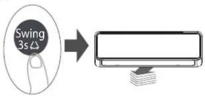
If continue to press the SWING button, five different airflow directions can be set. The louver can be move at a certain range each time you press the button. Press the button until the direction you prefer is reached.
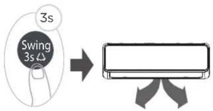
Keep pressing this button more than 3 seconds, the vertical louver swing function is activated. (Model dependent)
Press Swing button Set airflow direction
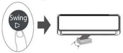
The horizontal louver will swing up and down automatically when pressing Swing button.
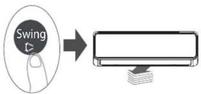
If continue to press the SWING button, five different airflow directions can be set. The louver can be move at a certain range each time you press the button. Press the button until the direction you prefer is reached.
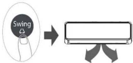
Press this button, the vertical louver swing function is activated.
LED DISPLAY
Press this button to turn on and turn off the display on the indoor unit.
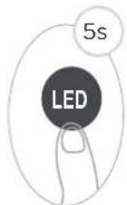
Press this button more than 5 seconds(some units)
Keep pressing this button more than 5 seconds, the indoor unit will display the actual room temperature. Press more than 5 seconds again will revert back to display the setting temperature.
Cool/Heat Flash Function
Press this button
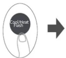
When you press this button in COOL mode, the Cool Flash technology can drive your whole room to the instant cool. With large air volume and long airflow, the temperature of the whole room can be reduced in a short time.
When you press this button in HEAT mode, with fast and strong heating airflow, the Heat Flash technology can warm up your whole room in a short time.
ECO/GEAR function
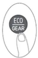

Press this button to enter the energy efficient mode in a sequence of following:
ECO → GEAR(75%) → GEAR(50%) → Previous setting mode → ECO.....
Note: This function is only available under COOL mode.
ECO operation:
Under cooling mode, press this button, the remote controller will adjust the temperature automatically to 24^ C/75°F, fan speed of Auto to save energy (only when the set temperature is less than 24^ C/75°F). If the set temperature is above 24^ C/75°F, press the ECO button, the fan speed will change to Auto, the set temperature will remain unchanged.
NOTE: Pressing the ECO button, or modifying the mode or adjusting the set temperature to less than 24^ C/75°F will stop ECO operation. Under ECO operation, the set tmeperature should be 24^ C/75°F or above, it may result in insufficient cooling. If you feel uncomfortable, just press the ECO button again to stop it.
GEAR operation:
Press the ECO/GEAR button to enter the GEAR operation as following:
75%(up to 75% electrical energy consumption) → 50%(up to 50% electrical energy consumption)→ Previous setting mode.
Under GEAR operation, the display on the remote controller will alternate between electrical energy consumption and set temperature.
Silence function
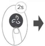
Keep pressing Fan button for more than 2 seconds to activate/disable Silence function.
Due to low frequency operation of compressor, it may result in insufficient cooling and heating capacity. Press ON/OFF, Mode, Sleep, Boost or Clean button while operating will cancel silence function.
FP function
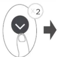
Press this button 2 times during one second under HEAT Mode and setting temperature of 16^ C/ 60^ F to activate the FP function.
The unit will operate at high fan speed (while compressor on) with temperature automatically set to 8^ C/ 46^ F.
SET function
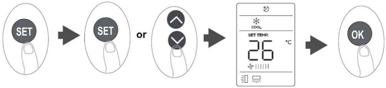
flowchart
graph LR
    A["SET"] --> B["SET"]
    B --> C["OR"]
    C --> D["SET TEMP. 26 °C"]
    D --> E["OK"]
- Press the SET button to enter the function setting, then press SET button or TEMP √ or TEMP ∧ button to select the desired function. The selected symbol will flash on the display area, press the OK button to confirm.
- To cancel the selected function, just perform the same procedures as above.
- Press the SET button to scroll through operation functions as follows:
Active clean(♂)→ Sleep(♀)→ Follow Me(♀)→ AP mode*(♀)
Active clean function
The Active Clean Technology washes away dust, and mold that may cause odors when it adheres to the heat exchanger by automatically freezing and then rapidly thawing the frost. When this function is turned on, the indoor unit display window appears "CL", after 20 to 130 minutes, the unit will turn off automatically and cancel CLEAN function.
Sleep function( 😊 ) :
The SLEEP function is used to decrease energy use while you sleep(and don't need the same temperature settings to stay comfortable).
NOTE: The SLEEP function is not available in FAN and DRY mode.
AP function( ) (some units):
Choose AP mode to do wireless network configuration. For some units, it doesn't work by pressing the SET button. To enter the AP mode, continuously press the LED button seven times in 10 seconds.
Follow me function( 👁 ):
The FOLLOW ME function enables the remote control to measure the temperature at its current location and send this signal to the air conditioner every 3 minutes interval. When using AUTO, COOL or HEAT modes, measuring ambient temperature from the remote control (instead of from the indoor unit itself) will enable the air conditioner to optimize the temperature around you and ensure maximum comfort.
NOTE: Press and hold Cool/Heat Flash button for seven seconds to start/stop memory feature of Follow Me function.
- If the memory feature is activated, "On" displays for 3 seconds on the screen.
- If the memory feature is stopped, "OF" displays for 3 seconds on the screen.
- While the memory feature is activated, press the ON/OFF button, shift the mode or power failure will not cancel the Follow me function.
App Setup And Operation
Wireless control feature
Applicable system: iOS, Android
- Please keep your APP up to date with the latest version.
- Due to special situation may be occurred, we explicitly claims below: Not all of the Android and iOS system are compatible with APP. We will not be responsible for any issue as a result of the incompatibility.
Wireless safety strategy
- Smart kit only support WPA-PSK/WPA2-PSK encryption and none encryption. WPA-PSK/WPA2-PSK encryption is recommended.
CAUTIONS:
- Due to different network situation, control process may return time-out sometimes. If this situation occurs, the display between board and APP may not be the same, please do not feel confused.
- Smart Phone camera needs to be 5 million pixelsor above to make sure scan QR code well.
- Due to different network situation, sometimes, request time-out could happen, thus, it is necessary to do network configuration again.
- The APP system is subject to update without prior notice for product function improvement.
- The actual network configuration process may be slightly different from the manual, the actual process shall prevail.
- Please check the Service Website for more information.
SPECIFICATION:
- APP control module model: EU-SK110, US-SK110
• Antenna Type: Printed PCB Antenna
• Frequency Band: 2400-2483.5MHz
• Operation Temperature:0°C\~45°C/32°F\~113°F
• Operation Humidity: 10%\~85%
• Power Input: DC 5V/500mA
• Maximum TX Power: <20dBm
PREPARATION
- Please ensure your mobile device is connected to wireless router. Also, the wireless router has already connected to Internet before doing user registration and network configuration.
- Make sure your mobile device has already been connected to the wireless network which you want to use. Also, you need to forget other irrelevant wireless network in case it influences your configuration process.
Download and install app
-
Ensure the mobile phone is connected to your home network.
-
Scan the QR code or search for the MSmartHome application from the Google Play Store or Apple App Store on a smart device.
-
Ensure the mobile phone is connected to your home network.
- Scan the QR code or search for the MSmartHome application from the Google Play Store or Apple App Store on a smart device.
Network configuration
CAUTIONS:
- It is necessary to forget any other around network and make sure the Android or iOS device just connect to the wireless network you want to configure.
- Make sure the Android or iOS device wireless function works well and can be connected back to your original wireless network automatically.
Kindly reminder:
- User must finish all the steps in 8 minutes after powering on air conditioner, otherwise you need to power on it again.
NOTE:
• Make sure your devices are powered on.
- Keep your mobile phone close enough to your device when you are connecting network to your device.
- Connect your mobile phone to the wireless network at home, and make sure you know the
- password of the network.
- Check if your router supports 2.4 GHz wireless band and turn it on. If you are not sure whether the router supports 2.4 GHz band, please contact the router manufacturer.
- The device cannot connect to the wireless that requires authentication, and it usually appears in public area such as hotels, restaurants, etc. Please connect to a wireless network that does not require authentication.
- It is recommended to use a wireless network name that only contains letters and numbers.
- If your wireless network name contains special characters, please modify it in the router. Turn off the WLAN+ (Android) or WLAN Assistant (iOS) function of your mobile phone when connecting network to your devices.
- In the case that your device connected to wireless network before but it needs to reconnect, please click "+" on app Home page, and add your device again by the device category and model according to the instructions on app.
Register and log in
Open the MSmartHome app, and create a new account to start (you can also register through a third-party account). If you already had an existing account, use the account to log in.
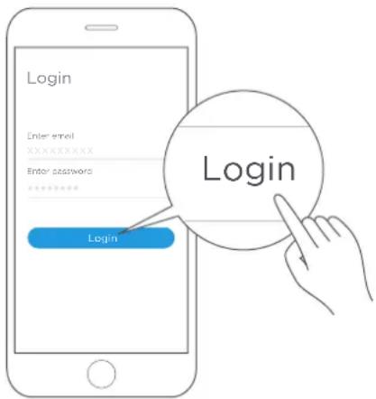
Connect your devices to MSmartHome
- Please make sure your mobile phone is connected to wireless network. If not, go to Settings and turn on the wireless connection, select and connect to a wireless network. Also please turn on the Bluetooth on your phone. If not, go to Settings and turn it on.
- Please power on your devices.
- Open MSmartHome app on your phone.
- If a message of "Smart devices discovered nearby" appears, click to add.
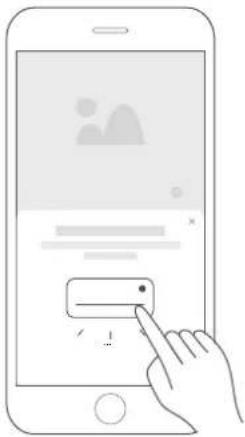
natural_image
Illustration of a hand interacting with a smartphone screen displaying a simple UI element (no text or symbols present)- If no message appears, select "+" on the page and select your device in the list of nearby devices available. If your device is not listed, please add your device manually by the device category [Air Conditioner] and device model [Split AC].
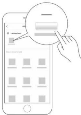
- Connect your device to APP according to the instructions on app. If the connection fails, please follow the instructions provided by the app to continue with the operation.
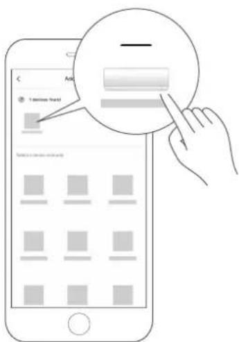
How to use APP
Please ensure both your mobile device and air conditioner are connected to the Internet before using app to control the air conditioner via internet, please follow the steps:
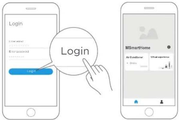
- Click "Login"
NOTE:
Not all the function of the APP is available on air conditioner.
For example: ECO, Boost,
Swing function, please check the
user manual to find more information.
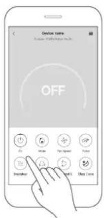
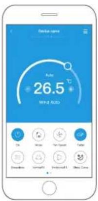
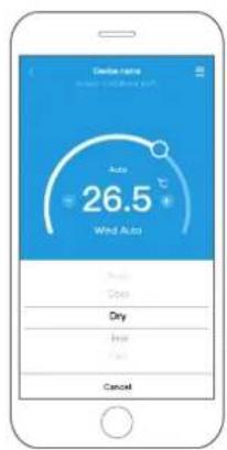
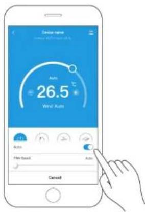
- Thus, user can control air conditioners on/off status, operation mode, temperature, fan speed and so on.
Special functions
Including: Schedule, Sleep curve, Energy Monitor, Bill Control and Check.
NOTE: Not all the unit can use these special function on the APP.
Thus, if the air conditioner
do not support the above function, the function will be hided from the function list.
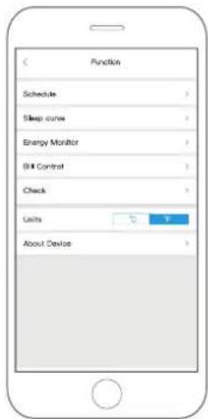
Schedule
Weekly, user can make an appointment to turn on or off the air conditioner on specific time. User also can choose circulation to keep the air conditioner under schedule control every week.
Sleep
Users can customize their own comfortable sleep by setting target temperature.
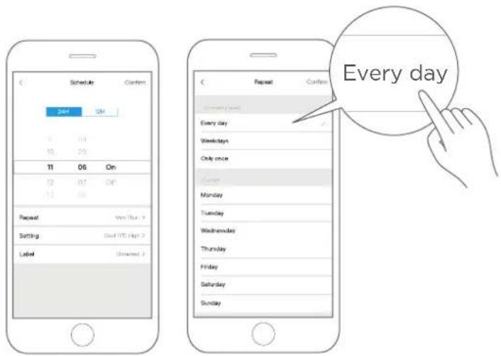
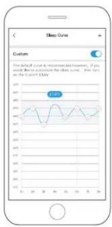
Energy Monitor(Only for some units)
User can simply monitor the electricity consumption of air conditioner by checking the chart and history record.
Bill Control(Only for some units)
User can set parameters to limit the electricity consumption over a period of time.
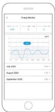
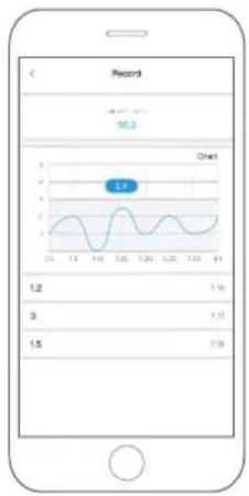
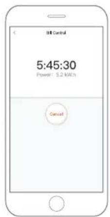
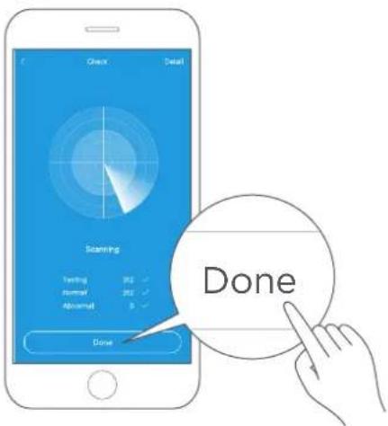
Check
User can simply check the air conditioner running status with this function. When finishing this procedure, it can display the normal items, abnormal items, and detail information.
APP DECLARATION
Hereby, we declare that this Smart kit is in compliance with the essential requirements and other relevant provisions of Directive 2014/53/EU. A copy of the full DoC is attached.
(European Union products only)
CAUTIONS:
Wireless module models: US-SK110, EU-SK110:
FCC ID: 2ADQOMDNA23
IC: 12575A-MDNA23
This device complies with Part 15 of the FCC Rules and it contains licence-exempt transmitter(s)/receiver(s) that comply with Innovation, Science and Economic Development Canada's licence-exempt RSS(s).
Operation is subject to the following two conditions:
- This device may not cause interference; and
- This device must accept any interference, including interference that may cause undesired operation of the device.
Only operate the device in accordance with the instructions supplied. Changes or modifications to this unit not expressly approved by the party responsible for compliance could void the user's authority to operate the equipment. This device complies with FCC
radiation exposure limits set forth for an uncontrolled environment. In order to avoid the possibility of exceeding the FCC radio frequency exposure limits, human proximity to the antenna shall not be less than 20cm (8 inches) during normal operation.
NOTE: This equipment has been tested and found to comply with the limits for a Class B digital device, pursuant to part 15 of the FCC Rules. These limits are designed to provide reasonable protection against harmful interference in a residential installation. This equipment generates, uses and can radiate radio frequency energy and, if not installed and used in accordance with the instructions, may cause harmful interference to radio communications. However, there is no guarantee that interference will not occur in a particular installation. If this equipment does cause harmful interference to radio or television reception, which can be determined by turning the equipment off and on, the user is encouraged to try to correct the interference by one or more of the following measures:
-Reorient or relocate the receiving antenna.
-Increase the separation between the equipment and receiver.
-Connect the equipment into an outlet on a circuit different from that to which the receiver is connected.
-Consult the dealer or an experienced radio/TV technician for help.
CARE AND MAINTENANCE

CAUTION
- The cooling efficiency of your unit and your health would be damaged for the glogged AC, Make sure to clean the filter every two weeks.
- Always TURN OFF your AC system and disconnect its power supply before cleaning or maintenance.
- Do not touch air freshening (Plasma) filter at least 10 minutes after turning off the unit.
- Only use a soft, dry cloth to wipe the unit clean. You can use a cloth soaked in warm water to wipe it clean if the unit is especially dirty.
- Do not use chemicals or chemically treated cloths to clean the unit
- Do not use benzene, paint thinner, polishing powder or other solvents to clean the unit. They can cause the plastic surface to crack or deform.
- Do not use water hotter than 40^ (104°F) to clean the front panel. This can cause the panel to deform or become discolored.
Cleaning Your Indoor Unit, Air Filter
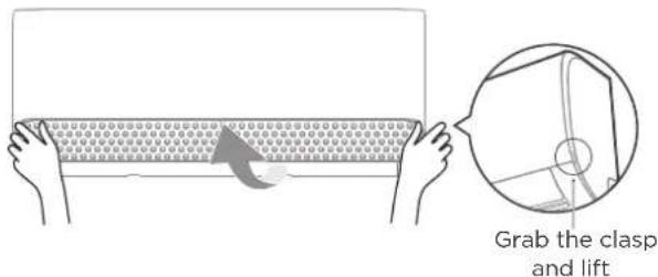
Step 1:
Lift the front panel of the indoor unit.
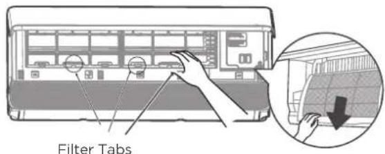
Step 2:
Grip the tab on the end of the filter, lift it up, then pull it towards yourself and pull the filter out.
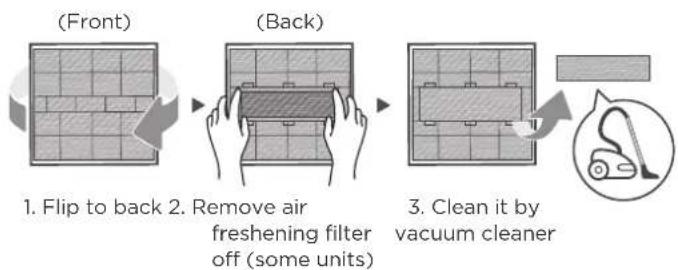
flowchart
graph LR
    A["(Front)"] --> B["(Back)"]
    B --> C["3. Clean it by vacuum cleaner"]
    C --> D["1. Flip to back 2. Remove air freshening filter off (some units)"]
Step 3:
If your filter has a small air freshening filter, unclip it from the larger filter. Clean this air freshening filter with a hand-held vacuum.
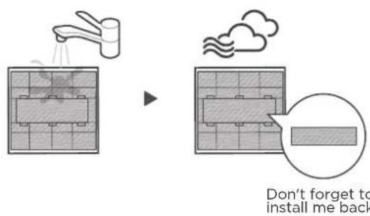
Step 4:
Clean the large air filter with warm, soapy water. Be sure to use a mild detergent. Rinse the filter with fresh water, then shake off excess water. Dry it in a cool, dry place, and refrain from exposing it to direct sunlight.
natural_image
Decorative banner with decorative sparkles and a textured border (no text or symbols)Step 5:
When dry, re-clip the air freshening filter to the larger filter, then slide it back into the indoor unit. Finally, Close the front panel of the indoor unit.

CAUTION
- Before changing the filter or cleaning, turn off the unit and disconnect its power supply.
- When removing filter, do not touch metal parts in the unit. The sharp metal edges can cut you.
- Do not use water to clean the inside of the indoor unit. This can destroy insulation and cause electrical shock.
- Do not expose filter to direct sunlight when drying. This can shrink the filter.
- Any maintenance and cleaning of outdoor unit should be performed by an authorized dealer or a licensed service provider.
- Any unit repairs should be performed by an authorized dealer or a licensed service provider.
Air Filter Reminders (Optional)
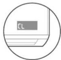
Display window: "CL"
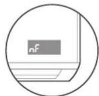
Display window: "nF"
Air Filter Cleaning Reminder
- After 240 hours of use, the display window on the indoor unit will flash "CL." This is a reminder to clean your filter. After 15 seconds, the unit will revert to its previous display.
- To reset the reminder, press the LED button on your remote control 4 times, or press the MANUAL CONTROL button 3 times. If you don't reset the reminder, the "CL" indicator will flash again when you restart the unit.
Air Filter Replacement Reminder
- After 2,880 hours of use, the display window on the indoor unit will flash "nF." This is a reminder to replace your filter. After 15 seconds, the unit will revert to its previous display.
- To reset the reminder, press the LED button on your remote control 4 times, or press the MANUAL CONTROL button 3 times. If you don't reset the reminder, the "nF" indicator will flash again when you restart the unit.
Maintenance your AC.
Maintenance - Long Periods of Non-Use
If you plan not to use your air conditioner for an extended period of time, do the following:
natural_image
Simple line drawing of a hand cleaning a grid (no text or symbols)Clean all filters Turn on FAN function until
natural_image
Simple line icon of a house with wavy lines indicating airflow or water (no text or symbols)unit dries out completely
natural_image
Prohibition symbol with a circle and diagonal line crossing through it, no text or numbers present.Turn off the unit and disconnect the power
natural_image
Simple line drawing of a mobile phone with a card and scroll (no text or symbols)Remove batteries
from remote control
Maintenance - Pre-Season Inspection
After long periods of non-use, or before periods of frequent use, do the following:
Check for damaged wires
natural_image
Hand cleaning a grid with a magnifying glass (no text or symbols)Clean all filters Check for leaks
natural_image
Prohibition sign with no text, numbers, or symbols (no readable document text)
natural_image
No smoking symbol (prohibited sign) with no accompanying text or labels
natural_image
Prohibition sign with a diagonal line and house icon, no text or symbols present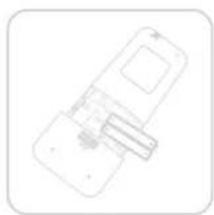
natural_image
Simple line drawing of a smartphone with a scroll wheel (no text or symbols)all air inlets and outlets
Replace batteriesMake sure
TROUBLESHOOTING

CAUTION
If any of the following conditions occurs, turn off your unit immediately!
• The power cord is damaged or abnormally warm
- You smell a burning odor
• The unit emits loud or abnormal sounds
- A power fuse blows or the circuit breaker frequently trips
• Water or other objects fall into or out of the unit
DO NOT ATTEMPT TO FIX THESE YOURSELF! CONTACT AN AUTHORIZED SERVICE PROVIDER IMMEDIATELY.
Common Issues
The following problems are not a malfunction and in most situations will not require repairs.
| Issue Possible Causes | |
| Unit does not turn on when pressing ON/OFF button | The Unit has a 3-minute protection feature that prevents the unit from overloading. The unit cannot be restarted within three minutes of being turned off. |
| The unit changes from COOL/HEAT mode to FAN mode | The unit may change its setting to prevent frost from forming on the unit. Once the temperature increases, the unit will start operating in the previously selected mode again.The set temperature has been reached, at which point the unit turns off the compressor. The unit will continue operating when the temperature fluctuates again. |
| The indoor unit emits white mist | In humid regions, a large temperature difference between the room's air and the conditioned air can cause white mist. |
| Both the indoor and outdoor units emit white mist | When the unit restarts in HEAT mode after defrosting, white mist may be emitted due to moisture generated from the defrosting process. |
| The indoor unit makes noises | A rushing air sound may occur when the louver resets its position.A squeaking sound may occur after running the unit in HEAT mode due to expansion and contraction of the unit's plastic parts. |
| Both the indoor unit and outdoor unit make noises | Low hissing sound during operation: This is normal and is caused by refrigerant gas flowing through both indoor and outdoor units. |
| Low hissing sound when the system starts, has just stopped running, or is defrosting: This noise is normal and is caused by the refrigerant gas stopping or changing direction. | |
| Squeaking sound: Normal expansion and contraction of plastic and metal parts caused by temperature changes during operation can cause squeaking noises. | |
| The outdoor unit makes noises | The unit will make different sounds based on its current operating mode. |
| Dust is emitted from either the indoor or outdoor unit | The unit may accumulate dust during extended periods of non-use, which will be emitted when the unit is turned on. This can be mitigated by covering the unit during long periods of inactivity. |
| The unit emits a bad odor | The unit may absorb odors from the environment (such as furniture, cooking, cigarettes, etc.) which will be emitted during operations. |
| The unit's filters have become moldy and should be cleaned. | |
| The fan of the outdoor unit does not operate | During operation, the fan speed is controlled to optimize product operation. |
| Operation is erratic, unpredictable, or unit is unresponsive | Interference from cell phone towers and remote boosters may cause the unit to malfunction.In this case, try the following:Disconnect the power, then reconnect.Press ON/OFF button on remote control to restart operation. |
NOTE: If problem persists, contact a local dealer or your nearest customer service center. Provide them with a detailed description of the unit malfunction as well as your model number.

CAUTION
When troubles occur, please check the following points before contacting a repair company.
| Problem Possible | Causes Solution | |
| Poor Cooling Performance | Temperature setting may be higher than ambient room temperature | Lower the temperature setting |
| The heat exchanger on the indoor or outdoor unit is dirty | Clean the affected heat exchanger | |
| The air filter is dirty | Remove the filter and clean it according to instructions | |
| The air inlet or outlet of either unit is blocked | Turn the unit off, remove the obstruction and turn it back on | |
| Doors and windows are open | Make sure that all doors and windows are closed while operating the unit | |
| Excessive heat is generated by sunlight | Close windows and curtains during periods of high heat or bright sunshine | |
| Too many sources of heat in the room (people, computers, electronics, etc.) | Reduce amount of heat sources | |
| Low refrigerant due to leak or long-term use | Check for leaks, re-seal if necessary and top off refrigerant | |
| SILENCE function is activated (optional function) | SILENCE function can lower product performance by reducing operating frequency. Turn off SILENCE function. | |
| Problem Possible Causes | Solution | |
| The unit is not working | Power failure | Wait for the power to be restored |
| The power is turned off Turn on the power | ||
| The fuse is burned out | Replace the fuse | |
| Remote control batteries are dead | Replace batteries | |
| The Unit's 3-minute protection has been activated | Wait three minutes after restarting the unit | |
| Timer is activated | Turn timer off | |
| The unit starts and stops frequently | There's too much or too little refrigerant in the system | Check for leaks and recharge the system with refrigerant. |
| Incompressible gas or moisture has entered the system. | Evacuate and recharge the system with refrigerant | |
| The compressor is broken Replace the compressor | ||
| The voltage is too high or too low | Install a manostat to regulate the voltage | |
| Poor heating performance | The outdoor temperature is extremely low | Use auxiliary heating device |
| Cold air is entering through doors and windows | Make sure that all doors and windows are closed during use | |
| Low refrigerant due to leak or long-term use | Check for leaks, re-seal if necessary and top off refrigerant | |
| Indicator lamps continue flashing | ||
| Error code appears and begins with the letters as the following in the window display of indoor unit:• E(x), P(x), F(x)• EH(xx), EL(xx), EC(xx)• PH(xx), PL(xx), PC(xx) | The unit may stop operation or continue to run safely. If the indicator lamps continue to flash or error codes appear, wait for about 10 minutes. The problem may resolve itself.If not, disconnect the power, then connect it again. Turn the unit on.If the problem persists, disconnect the power and contact your nearest customer service center. | |
NOTE: If your problem persists after performing the checks and diagnostics above, turn off your unit mmediately and contact an authorized service center.
TRADEMARKS, COPYRIGHTS AND LEGAL STATEMENT
Midea logo, word marks, trade name, trade dress and all versions thereof are valuable assets of Midea Group and/or its affiliates (“Midea”), to which Midea owns trademarks, copyrights and other intellectual property rights, and all goodwill derived from using any part of an Midea trademark. Use of Midea trademark for commercial purposes without the prior written consent of Midea may constitute trademark infringement or unfair competition in violation of relevant laws.
This manual is created by Midea and Midea reserves all copyrights thereof. No entity or individual may use, duplicate, modify, distribute in whole or in part this manual, or bundle or sell with other products without the prior written consent of Midea.
All the described functions and instructions were up to date at the time of printing this manual. However, the actual product may vary due to improved functions and designs.
DISPOSAL AND RECYCLING
Important instructions for environment(European Disposal Guidelines)
Compliance with the WEEE Directive and Disposing of the Waster Product: This product complies with EU WEEE Directive (2012/19/EU). This product bears a classification symbol for waster electrical and electronic equipment (WEEE).
This symbol indicates that this product shall not be disposed with other household wastes at the end of its service life. Used device must be returned to official collection point for recycling of electrical electronic devices. To find these collection systems please contact to your local authorities or retailer where the product was purchased. Each household performs important role in recovering and recycling of old appliance. Appropriate disposal of used appliance helps prevent potential negative consequences for the environment and human health.
natural_image
Symbol of a trash bin crossed out by two crossed lines, with no text or labels present.DATA PROTECTION NOTICE
For the provision of the services agreed with the customer,
we agree to comply without restriction with all stipulations of applicable data protection law, in line with agreed countries within which services to the customer will be delivered, as well as, where applicable, the EU General Data Protection Regulation (GDPR).
Generally, our data processing is to fulfil our obligation under contract with you and for product safety reasons, to safeguard your rights in connection with warranty and product registration questions. In some cases, but only if appropriate data protection is ensured, personal data might be transferred to recipients located outside of the European Economic Area.
Further information are provided on request. You can contact our Data Protection Officer via MideaDPO@midea.com. To exercise your rights such as right to object your personal date being processed for direct marketing purposes, please contact us via MideaDPO@midea.com. To find further information, please follow the QR Code.
The design and specifications are subject to change without prior notice for product improvement. Consult with the sales agency or manufacturer for details. Any updates to the manual will be uploaded to the service website, please check for the latest version.
Importer:
FG EUROPE SA 128, VOULIAGMENIS AVE
16674 GLYFADA, GREECE
Manufacturer: GD Midea Air-Conditioning Equipment Co., Ltd.
Lingang Road Beijiao Shunde Foshan Guangdong
People's Republic of China 528311
RED Declaration of Conformity (DoC)
Unique identification of this DoC: ....
We,
GD Midea Air-Conditioning Equipment Co., Ltd. Lingang Road, Beijiao, 528311 Shunde, Foshan, Guangdong, PEOPLE'S REPUBLIC OF CHINA
declare under our sole responsibility that the product:
product name: Split type air conditioner
trade name: Midea
type or model: EU-SK110, Split type air conditioner
relevant supplementary information: ....
(e.g. lot, batch or serial number, sources and numbers of items)
to which this declaration relates is in conformity with the essential requirements and other relevant requirements of the RE Directive (2014/53/EU).
The product is in conformity with the following standards and/or other normative documents:
HEALTH & SAFETY (Art. 3(1)(a)): EN IEC 62311:2020, EN 60335-2-
40:2003+A11:2004+A12:2005+A1:2006+A2:2009+A13:2012,EN 60335-
1:2012+A11:2014+A13:2017+A1:2019+A14:2019+A2:2019+A15:2021,EN 62233:2008
EMC (Art. 3(1)(b)): EN 301 489-1 V2.2.3: 2019, EN 301 489-17 V3.2.4 :2020,
EN IEC 55014-1:2021, EN IEC 55014-2:2021, EN IEC 61000-3-2:2019+A1:2021, EN
61000-3-3:2013+A1:2019+A2:2021
SPECTRUM (Art. 3(2)): EN 300 328 V2.2.2 (2019-07)
OTHER (incl. Art. 3(3) and voluntary specs): ....
(title and/or number and date of issue of the standard(s) or other normative document(s))
Limitation of validity (if any): ....
Supplementary information:
Notified body involved: N/A....
Technical file held by: GD Midea Air-Conditioning Equipment Co., Ltd.
Place and date of issue (of this DoC): Foshan/2023-01-07
Signed by or for the manufacturer: ....
(Signature of authorised person)
Name (in print): Silvia Su.
Title:

make yourself at home
www.midea.com
© Midea 2022 all rights reserved
CS021UI-CB(OBM)
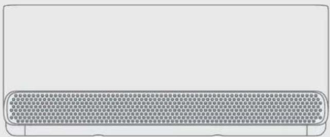
natural_image
Front view of a rectangular electronic device with a grid-patterned front panel and rounded corners (no text or symbols)MSmartHome
(1)
(2)
natural_image
Simple line icon of a window with horizontal lines inside, no text or symbols present
natural_image
Simple line drawing of a water spray with a pipe and wavy lines (no text or symbols)
natural_image
Silhouette of a person shouting into a megaphone (no text or symbols)Βος από τη
natural_image
Gray gear and chain link icon on white background (no text or symbols)
natural_image
Simple icon of a washing machine with a circular label showing '1m' (no text or symbols beyond the label)
natural_image
Pure electrical circuit lines without any symbolsΤύπος Α Τύπος Β
Βήμα 3:
natural_image
Pure mechanical diagram showing a bracket and pipe connection without any text, numbers, or symbolsΔΙΟΡΘΩΣΗ
natural_image
Simple line drawing of a pipe joint with a valve and a cross symbol (no text or labels)ΛΑΘΟΣ
natural_image
Pure diagram of a pipe connection with a wall and ground, no text or symbols presentΛΑΘΟΣ
natural_image
Simple line drawing of a container connected to a bucket with a vertical wall and a cross symbol (no text or labels)ΛΑΘΟΣ
natural_image
Abstract gear and chain link icon symbol (no text or labels)
natural_image
Simple line drawing of a sun and a water drop with raindrops, no text or symbols present
natural_image
Simple line drawing of a fan with a snowflake symbol beside it (no text or labels)
natural_image
Technical line drawing of a front-end air conditioner unit with fan and ventilation slots (no text or symbols)| Διαστάσεις εξωτερικής μονάδας (mm) W x H x D | Διαστάσεις τοποθέτησης | |
| Απόσταση Α (mm) | Απόσταση Β (mm) | |
| 680x542x248 (26,8"x21,3"x9,8") 452 (17,8") 230 (9,1") | ||
| 720x495x270 (28,3"x19,5"x10,6") 452 (17,8") 255 (10,0") | ||
| 765x555x303 (30,1"x21,8"x11,9") 452 (17,8") 286 (11,3") | ||
| 805x554x330 (31,7"x21,8"x12,9") 511 (20,1") 317 (12,5") | ||
| 890x673x342 (35,0"x26,5"x13,5") 663 (26,1") 354 (13,9") | ||
| 946x810x420 (37,2"x31,9"x16,5") 673 (26,5") 403 (15,9") | ||
| 946x810x410 (37,2"x31,9"x16,1") | 673 (26,5") 403 (15,9") | |
natural_image
Mechanical component with mounting holes and a labeled part (no readable text or symbols)natural_image
3D mechanical component diagram showing a bracket with mounting flanges and a central hatched area (no text or symbols)natural_image
Two identical line drawings of a curved mechanical part with mounting holes, shown in two different angles (no text or symbols)natural_image
Diagram of a remote control device with internal circuitry and an arrow indicating a component (no text or symbols)natural_image
Illustration of a wall-mounted air conditioner unit next to a handheld device (no text or symbols visible)4
ΕΠΙΛΟΓΗ FAN SPEED
(ΤΑΧΥΤΗΤΑ ΑΝΕΜΙΣΤΗΡΑ)

AU-100%
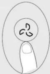
ΕΞΗΓΗΣΗ ΛΕΙΤΟΥΡΓΙΑΣ
natural_image
Illustration of a hand holding a remote control panel with arrows indicating movement (no text or symbols)
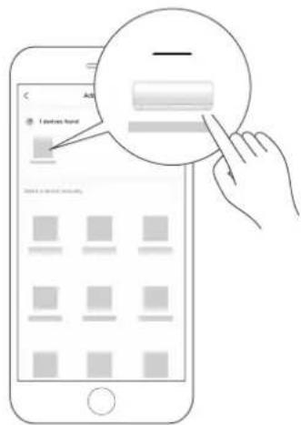
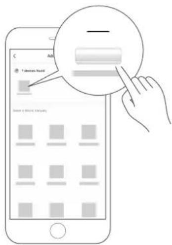
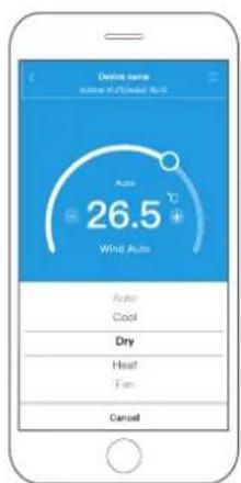
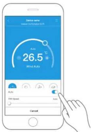
Πρόγραμμα
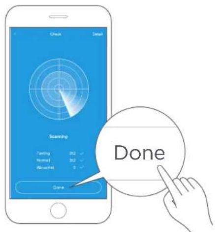
'Υπνος
'Ελεγχος
natural_image
Illustration of hands holding a rectangular object with patterned texture, alongside a magnified inset showing a circular detail (no text or symbols)natural_image
Decorative banner with sparkles and a textured border (no text or symbols)Βήμα 5:
natural_image
Simple line drawing of a hand cleaning a grid with a magnifying glass (no text or symbols)natural_image
Simple line icon of a house with wavy lines indicating airflow or water (no text or symbols)natural_image
Prohibition symbol with crossed-out arrow and circle, no text or numbers presentnatural_image
Simple line drawing of a mobile phone with a smartphone and a tablet (no text or symbols)natural_image
Prohibition sign with crossed-out lightning bolt and explosion symbol (no text)natural_image
Illustration of a hand cleaning a grid with a magnifying glass (no text or symbols)natural_image
Prohibition sign with no text or symbols, featuring a circle containing a diagonal line and a flame-like shape at the bottom (no readable text)natural_image
Prohibition sign with no text or symbols inside a circle (no readable text)natural_image
Prohibition sign with a diagonal line crossing over a building silhouette (no text or symbols)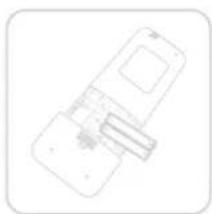
natural_image
Simple line drawing of a smartphone with a card and scroll (no text or symbols)natural_image
Symbol of a trash bin crossed with a diagonal line and a horizontal bar below (no text or labels)GD Midea Air-Conditioning Equipment Co., Ltd. Lingang Road, Beijiao, 528311 Shunde, Foshan, Guangdong, PEOPLE'S REPUBLIC OF CHINA
EMC (Art. 3(1)(b)): EN 301 489-1 V2.2.3: 2019,EN 301 489-17 V3.2.4 :2020,
EN IEC 55014-1:2021, EN IEC 55014-2:2021, EN IEC 61000-3-2:2019+A1:2021, EN
61000-3-3:2013+A1:2019+A2:2021
SPECTRUM (Art. 3(2)): EN 300 328 V2.2.2 (2019-07)
GD Midea Air-Conditioning Equipment Co., Ltd
make yourself at home
www.midea.com
© Midea 2022 all rights reserved
CS021UI-CB(OBM)
16122000A73095
- USER MANUAL
- THANK YOU LETTER
- CONTENTS
- SAFETY PRECAUTIONS
- WARNING
- WARNING FOR PRODUCT USE
- ELECTRICAL WARNINGS
- TAKE NOTE OF FUSE SPECIFICATIONS
- UV-C lamp(Applicable to the unit contains an UV-C lamp only)
- WARNINGS FOR PRODUCT INSTALLATION
- CAUTION
- CLEANING AND MAINTENANCE WARNINGS
- Note about Fluorinated Gasses(Not applicable to the unit using R290 Refrigerant)
- WARNING FOR USING R32/R290 REFRIGERANT
- SPECIFICATIONS
- NOTE ON ILLUSTRATIONS:
- PRODUCTION INSTALLATION
- ACCESSORIES
- It would be perfect you had these tools
- INSTALLATION SUMMARY - INDOOR UNIT
- Install You Indoor Unit
- Select installation location
- NOTE : Prior to installation
- Proper installation locations meet the following standards:
- DO NOT install unit in the following locations:
- NOTE: FOR PRODUCT INSTALLATION
- Drill wall hole for connective piping
- Determine wall hole location
- NOTE : The wall hole size
- Step 1:
- Step 2:
- Step 3:
- NOTE : FOR CONCRETE OR BRICK WALLS
- Step 4:
- Drill wall hole
- Install refrigerant pipe & drain hose
- NOTE
- Prepare refrigerant piping
- NOTE ON DRAIN HOSE PLACEMENT
- CORRECT
- NOT CORRECT
- PLUG THE UNUSED DRAIN HOLE
- Connect signal and power cables
- Cable Types(Not applicable for North America)
- Minimum Cross-Sectional Area of
- Power and Signal Cables (For reference)
- CHOOSE THE RIGHT CABLE SIZE
- In North America
- DO NOT MIX UP LIVE AND NULL WIRES
- 5
- Wrap piping & Cables
- Do not intertwine signal calbe with other wires
- DRAIN HOSE MUST BE ON BOTTOM
- DO NOT WRAP ENDS OF PIPING
- Mount indoor unit
- If you installed new connective piping to the outdoor unit, do the following:
- If refrigerant piping is already embedded in the wall, do the following:
- NOTE : UNIT IS ADJUSTABLE
- Install Your Outdoor Unit
- Select installation location
- CAUTION:
- If the unit is exposed to heavy wind:
- If the unit is frequently exposed to heavy rain or snow:
- If the unit is frequently exposed to salty air(seaside):
- Install drain joint(Heat pump unit only)
- NOTE : IN COLD CLIMATES
- 3
- Anchor Outdoor Unit
- WHEN DRILLING INTO CONCRETE, EYE PROTECTION IS RECOMMENDED AT ALL TIME.
- If you will install the unit on the ground or on a concrete mounting platform, do the following:
- If you will install the unit on a wall-mounted bracket, do the following:
- 4
- WARNING - Before the Operation
- Prepare the cable for connection
- Pay attention to live wire
- How to properly connect the wire lines.
- Step 2: Step 1:
- 1
- Piping Connection Precautions
- Note on Pipe Length
- Connection Instructions – Refrigerant Piping
- Step 1: Cut pipes
- DO NOT DEFORM PIPE WHILE CUTTING
- Step 2: Remove burrs
- Step 3: Flare pipe ends
- Refer to Torque Requirement to connect pipes
- MINIMUM BEND RADIUS
- Instructions for Connecting Piping to Indoor Unit
- Step 1: Step 2:
- TORQUE REQUIREMENTS
- DO NOT USE EXCESSIVE TORQUE
- Connecting Piping to Outdoor Unit
- Air Evacuation
- NOTE : PREPARATIONS AND PRECAUTIONS
- BEFORE PERFORMING EVACUATION
- Evacuation Instructions
- OPEN VALVE STEMS GENTLY
- NOTE ON ADDING REFRIGERANT
- ADDITIONAL REFRIGERANT PER PIPE LENGTH
- DO NOT MIX REFRIGERANT TYPES.
- Electrical And Gas Leak Checks
- WARNING - RISK OF ELECTRIC SHOCK
- BEFORE TEST RUN
- Electrical Safety Checks
- Check Grounding Work
- DURING TEST RUN
- Check for Electrical Leakage
- Gas Leak Checks
- Soap and Water Method
- Leak Detector Method
- AFTER PERFORMING GAS LEAK CHECKS
- Test Run
- Test Run Instructions
- DOUBLE-CHECK PIPE CONNECTIONS
- IF AMBIENT TEMPERATURE IS BELOW 16°C(60°F)
- Packing And Unpacking The Unit
- Instructions for packing and unpacking the unit:
- Unpacking:
- Indoor unit:
- Outdoor Unit
- Packing:
- Outdoor unit:
- OPERATION INSTRUCTIONS
- Operating Temperature
- FOR OUTDOOR UNITS WITH AUXILIARY ELECTRIC HEATER
- To further optimize the performance of your unit, do the following:
- More features
- - Auto-Restart
- • Anti-mildew(some units)
- • Wireless Control (Model dependent)
- • Active Clean function(some units)
- - Louver Angle Memory
- • Air Magic+ function(some units)
- - Coolflash function
- - Heatflash function
- • Refrigerant Leakage Detection
- • UV-C lamp function(some units)
- - Breezeless function
- - Breezeless Operation
- - Sleep Operation
- Setting Angle of Air Flow
- NOTE : Setting angle of air flow(Remote control)
- NOTE ON LOUVER ANGLES
- Manual Operation(without remote)
- CAUTION: For product use
- To operate your unit manually:
- Remote Control Operation
- Quick Start Guide
- NOT SURE WHAT A FUNCTION DOES?
- SPECIAL NOTE
- Handling the Remote Controller
- Inserting and Replacing Batteries
- BATTERY NOTES
- BATTERY DISPOSAL
- TIPS FOR USING REMOTE CONTROL
- NOTES FOR USING REMOTE CONTROL
- Buttons and Functions
- Remote Screen Indicators
- How to Use Basic Functions
- AUTO Mode
- NOTE:
- COOL or HEAT Mode
- DRY Mode
- FAN Mode
- Setting the TIMER
- TIMER ON setting
- TIMER OFF setting
- TIMER ON & OFF setting(example)
- How to Use Advanced Functions
- Swing function
- LED DISPLAY
- Cool/Heat Flash Function
- ECO/GEAR function
- ECO operation:
- GEAR operation:
- SET function
- Active clean function
- Sleep function( 😊 ) :
- AP function( ) (some units):
- Follow me function( 👁 ):
- App Setup And Operation
- Wireless control feature
- Applicable system: iOS, Android
- Wireless safety strategy
- CAUTIONS:
- SPECIFICATION:
- PREPARATION
- Download and install app
- Network configuration
- Kindly reminder:
- Register and log in
- Connect your devices to MSmartHome
- How to use APP
- Special functions
- Schedule
- Sleep
- Energy Monitor(Only for some units)
- Bill Control(Only for some units)
- Check
- APP DECLARATION
- Operation is subject to the following two conditions:
- CARE AND MAINTENANCE
- Cleaning Your Indoor Unit, Air Filter
- Step 5:
- Air Filter Reminders (Optional)
- Air Filter Cleaning Reminder
- Air Filter Replacement Reminder
- Maintenance your AC.
- Maintenance - Long Periods of Non-Use
- Maintenance - Pre-Season Inspection
- TROUBLESHOOTING
- Common Issues
- TRADEMARKS, COPYRIGHTS AND LEGAL STATEMENT
- DISPOSAL AND RECYCLING
- Important instructions for environment(European Disposal Guidelines)
- DATA PROTECTION NOTICE
- RED Declaration of Conformity (DoC)
- declare under our sole responsibility that the product:
- Βήμα 3:
- ΔΙΟΡΘΩΣΗ
- ΛΑΘΟΣ
- ΕΞΗΓΗΣΗ ΛΕΙΤΟΥΡΓΙΑΣ
- Πρόγραμμα
- 'Υπνος
- 'Ελεγχος
- Βήμα 5:
Brand : MIDEA
Model : CB1-09HRFN8-I
Category : Air-conditioner