
ZI-MBGS850D - Hydraulic Excavator Zipper - Free user manual and instructions
Find the device manual for free ZI-MBGS850D Zipper in PDF.


| Product Type | Hydraulic Excavator (Mini Excavator) |
| Brand | Zipper |
| Model | ZI-MBGS850D |
| EAN | 9120039235233 |
| Engine Type | 4-Stroke Gasoline Engine |
| Engine Power | 8.5 kW (approx.) |
| Starting System | Electric Start with Key |
| Hydraulic System | Hydraulic pump with multi-way valve |
| Operating Temperature Range | +10°C to +50°C |
| Storage Temperature Range | -25°C to +55°C |
| Dimensions (L x W x H) | 2500 x 950 x 1500 mm (approx.) |
| Weight | 850 kg (approx.) |
| Track Type | Rubber Crawler |
| Max Digging Depth | 1500 mm (approx.) |
| Bucket Capacity | 0.02 m³ (approx.) |
| Safety Devices | Battery disconnect switch, safety labels, emergency stop |
| Maintenance Intervals | Engine oil every 100 hours, hydraulic oil every 2000 hours |
| Intended Use | Earthworks and ground leveling |
| Operator Requirement | One person, physically and mentally fit |
| CE Compliance | Yes |
Frequently Asked Questions - ZI-MBGS850D Zipper
User questions about ZI-MBGS850D Zipper
0 question about this device. Answer the ones you know or ask your own.
Ask a new question about this device
Download the instructions for your Hydraulic Excavator in PDF format for free! Find your manual ZI-MBGS850D - Zipper and take your electronic device back in hand. On this page are published all the documents necessary for the use of your device. ZI-MBGS850D by Zipper.
USER MANUAL ZI-MBGS850D Zipper
natural_image
Green and black Zippers excavator with tracked arm and base mount (no visible text or symbols)
ZI-MBGS850D
EAN: 9120039235233
CE
YOUR
JOB.
OUR
TOOLS.
1 INHALT / INDEX
1 INHALT/INDEX....2
12.1 Intended use of the machine 37
12.1.1 Technical Restrictions 37
12.1.2 Prohibited applications / Dangerous misuse 37
12.2 User Requirements 37
12.3 Safety devices....37
12.4 General safety instructions....38
12.5 Special safety instructions for this machine 38
12.6 Hazard warnings....41
12.6.1 Hazardous situations....41
13 TRANSPORT....41
13.1.1 Transport by vehicle 41
14 ASSEMBLY 42
14.1 Preparation 42
14.1.1 Checking delivery content....42
14.2 Pre-operation check....42
15 OPERATION 43
15.1 Information on Initial Start-up....43
15.1.1 Notes for the first 50 operating hours....43
15.2 Operating instructions....43
15.3 Operation....43
15.3.1 Starting the engine....43
15.3.2 Stopping the engine 44
15.3.3 Functionality of the control levers of the attachments....44
15.3.4 Move the machine....46
15.3.5 Turns and changes of direction 47
16 CLEANING, MAINTENANCE, STORAGE, DISPOSAL....49
16.1 Cleaning 49
16.2 Maintenance....49
16.2.1 Maintenance plan 49
16.2.2 Check fuel tank level 50
16.2.3 Check the engine oil level....51
16.2.4 Check the hydraulic oil level 51
16.2.5 Check and maintenance hydraulic system....51
16.2.6 Lubrication points....52
16.2.7 Check bucket teeth 52
16.2.8 Battery....52
16.2.9 Replace the fuse....53
16.210 Check hydraulic hose and pipes 53
16.2.11 Check the bolts and nuts for tightening torque 53
16.2.12 Lubrication of external meshing gear of slewing bearing....54
16.2.13 Engine oil and filter element change....54
16.2.14 Check fuel line 55
16.215 Hydraulic oil and oil suction filter change 55
16.2.16 Electrical wiring and fuses 56
16.2.17 Fuel hose 56
16.2.18 Change bucket....56
16.3 Maintenance in special conditions 57
16.4 Work steps after the work has been carried out 57
16.5 Storage 57
16.6 Disposal....58
17 TROUBLESHOOTING....58
18 ELEKTRISCHER SCHALTPLAN / WIRING DIAGRAM 61
19 HYDRAULISCHER SCHALTPLAN / HYDRAULIC DIAGRAM 61
20 ERSATZTEILE / SPARE PARTS....62
EN CE-Conformal! - This product complies with the EC-directives.
EN READ THE MANUAL! Read the user and maintenance manual carefully and get familiar with the controls in order to use the machine correctly and to avoid injuries and machine defects.
EN ATTENTION! Ignoring the safety signs and warnings applied on the machine as well as ignoring the security and operating instructions can cause serious injuries and even lead to death.


EN Protective clothing!




EN Do not smoke or have open flames near the machine!

EN Do not touch parts that are hot from operation. Serious burns may result.

EN Keep your hands away!

EN Do not start the engine by shorting across starter terminals.

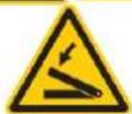
EN Keep out of this area to avoid serious personal injury or death.
EN Be careful with your hands.


EN Be aware, objects may be thrown while in use.

EN Use work gloves! Do not check for possible leakages with the bare hand.

EN Keep away from rotating parts.
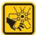
EN Keep away from fan!
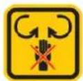
EN Keep hands away from moving parts. Danger of crushing and cutting!
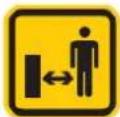
EN Keep safe distance!

EN Pay attention to safety when working in front of the machine.
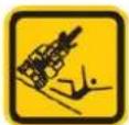
DE Kippgefahr!
EN Tipping hazard!
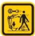
EN When leaving the machine, lower the bucket to the ground and remove the key!
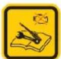
EN Stop before any break and engine maintenance and remove the spark plug cap!

EN Attention! The fan wheel heats up during operation.

EN Fuel and fuel vapours are highly flammable and explosive.
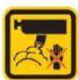
EN Do not touch hot components such as the exhaust, etc.

EN Only for working outside! The exhaust fumes are dangerous, containing carbon monoxide.
EN Missing or non-readable security stickers have to be replaced immediately.
natural_image
Top-down technical drawing of a vehicle chassis with no visible text or symbolsnatural_image
Simple line drawing of a person pushing a car with a yellow line indicating speed (no text or symbols)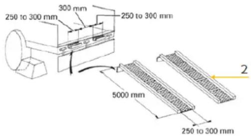
natural_image
Mechanical assembly diagram showing lever and pivot components (no text or labels visible)natural_image
Technical line drawing of an excavator on a construction site with numbered components (no text or symbols)Grundlegendes
natural_image
Close-up mechanical assembly showing internal components and a yellow highlight labeled '1' (no readable text or symbols)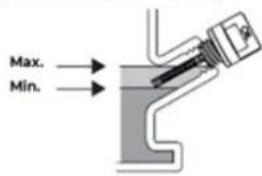
natural_image
Close-up of a mechanical excavator component with visible tracks and structural details (no text or symbols)natural_image
Close-up of a mechanical component with visible springs and bolts, no text or symbols presentnatural_image
Abstract black-and-white illustration of mechanical or electrical components with no visible text or symbolsWARNUNG:
natural_image
Close-up of a tracked excavator with visible tracks and levers (no text or symbols)natural_image
Close-up mechanical component with numbered annotations (1 and 2) highlighting a circular feature, no readable text or symbols beyond labels.Motoröl ablassen:
This manual contains information and important notes for safe commissioning and handling of the mini excavator ZI-MBGS6850D, hereinafter referred to as “machine” in this document.

This manual is part of the machine and must not be removed. Save it for later reference and if you let other people use the machine, add this manual to the machine.
Please read and note the safety instructions!
Before first use read this manual carefully. It eases the correct use of the machine and prevents misunderstanding and damages of machine.
Due to constant advancements in product design, construction, illustrations and contents may deviate slightly. If you notice any errors, please inform us.
We reserve the right to make technical changes!
Check the goods immediately after receipt and note any complaints on the consignment note when taking over the goods from the deliverer!
Transport damage must be reported separately to us within 24 hours.
ZIPPER MASCHINEN GmbH cannot accept any liability for transport damage that has not been reported.
Copyright
© 2024
This documentation is protected by copyright. All rights reserved! In particular, the reprint, translation and extraction of photos and illustrations will be prosecuted.
The place of jurisdiction is the regional court Linz or the court responsible for 4170 Haslach is valid.
Customer service contact
This section contains information and important notes on the safe commissioning and handling of the machine.

For your safety, read this manual carefully before commissioning. This will enable you to handle the machine safely and thus prevent misunderstandings as well as personal injury and damage to property. Pay special attention to the symbols and pictograms used on the machine as well as the safety information and danger warnings!
12.1 Intended use of the machine
The machine is designed exclusively for the following activities:
For carrying out earthworks and for levelling the ground after construction work has been completed within the technical specifications.
NOTE

ZIPPER MASCHINEN GmbH assumes no responsibility or warranty for any other use or use beyond this and for any resulting damage to property or injury.
12.1.1 Technical Restrictions
The machine is designed for the work under the following conditions:
Relative humidity: max. 70 %
Temperature (for operation) +10°C to +50°C
Temperature (storage, transport) -25^ C to +55^ C
12.1.2 Prohibited applications / Dangerous misuse
- Operating the machine without adequate physical and mental fitness.
- Operating the machine without knowledge of the manual.
- Modifying the machine design.
- Operating the machine in a potentially explosive environment.
- Operating the machine outside the technical limits specified in this manual.
- Removing of the safety markings attached to the machine.
- Modifying, circumventing or disabling the safety devices of the machine.
The non-intended use or the disregard of the explanations and instructions described in this manual will result in the expiration of all warranty claims and compensation claims for damages against ZIPPER MASCHINEN GmbH.
12.2 User Requirements
The machine is designed to be operated by one person. The prerequisites for operating the machine are physical and mental fitness as well as knowledge and understanding of the operating instructions. Persons who, due to their physical, sensory or mental capabilities, inexperience or lack of knowledge, are unable to operate the machine safely must not use the machine without supervision or instruction by a responsible person.
Please note that locally applicable laws and regulations determine the minimum age of the operator and may restrict the use of this machine!
Work on electrical components or equipment may only be carried out by a qualified electrician or under the guidance and supervision of a qualified electrician.
Put on your personal protective equipment before working on the machine.
12.3 Safety devices
The machine is equipped with the following safety devices:
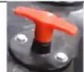
- Battery disconnect switch to disconnect the machine from the battery power supply
12.4 General safety instructions
To avoid malfunctions, damage and health impairments when working with the machine, the following points must be observed in addition to the general rules for safe working:
- Check the machine for completeness and function before starting. Only use the machine if the separating and other non-separating protective devices required for machining have are fitted.
- Make sure that the guards are in good working order and properly maintained.
- Ensure sufficient space around the machine.
- Ensure sufficient lighting conditions at the workplace to avoid stroboscopic effects.
- Keep the area around the machine free of obstacles (e.g. stones, etc.).
- Only use tools that are in perfect condition and free of cracks and other defects (e.g. deformations).
- Remove tool keys and other setting tools before switching on the machine.
- Check the machine's connections for strength before each use.
- Never leave the running machine unattended. Switch off the machine before leaving the working area and secure it against unintentional or unauthorized restarting.
- The machine may only be operated, maintained or repaired by persons who are familiar and who have been informed about the dangers arising from this work.
- Ensure that unauthorized persons keep a safety distance from the machine and keep children away from the machine.
• Always work with care and the necessary caution and never use excessive force. - Do not overload the machine.
- Wear close fitting protective work clothing and suitable protective equipment (eye protection or face protection, ear protection, safety-shoes, safety helmet, and work gloves only when handling tools).
- Never wear loose jewellery, loose clothing or accessories (e.g. tie, scarf).
- Do not work on the machine if you are tired, not concentrated or under the influence of medication, alcohol or drugs!
- Do not use the machine in areas where vapours of paints, solvents or flammable liquids represent a potential danger (danger of fire or explosion!).
- Shut down the machine before carrying out adjustment, changeover, cleaning, maintenance or servicing work, etc. Before starting work on the machine, wait until all tools or machine parts have come to a complete standstill and secure the machine against unintentional restarting.
12.5 Special safety instructions for this machine
WORKING AREA
- Familiarise yourself with the working environment before starting work.
- Before starting work, determine where gas and utility lines, the sewer system, underground power lines or overhead electrical lines are located and where other possible obstacles or sources of danger are located.
- Make sure that the arm or boom does not come into contact with any overhead electric lines. Always keep a safe distance (3m plus twice the line insulator length to overhead wires) from overhead electric lines.
- Check the working environment for hidden holes, obstacles, the supporting capacity of the ground and overhangs.
- Only operate the machine on solid ground with sufficient supporting capacity for the machine.
- Remove foreign objects that could unexpectedly start moving when passing over them.
- Reduce the driving speed if there may be foreign objects hidden on or near the ground (e.g.: when clearing snow or removing mud, dirt, etc.).
- Avoid operating the machine close to structures (e.g. overhangs) or objects that could fall on the machine.
- Always keep the machine at a sufficient distance from slope edges and excavation edges. The ground could give way under the weight of the machine.
- Do not dig underneath the machine.
- Be careful on slopes. Take special care on soft, rocky or frozen ground. Under these conditions, the machine may slip sideways. When driving on slopes, keep the bucket on the uphill side and just above the ground surface.
SAFE WORKING
- Be careful with heavy loads. Using oversized buckets or lifting heavy objects reduces machine stability.
- Never drive on slopes with an inclination of more than 15^ . The machine could tip over.
- Turn the machine slowly on slopes.
- Lifting a heavy load or swinging it over the side of the undercarriage can cause the machine to tip.
- Ensure that the machine is standing securely. Be especially careful in the vicinity of slopes or excavations that may collapse and cause the machine to tip or fall.
- Do not jump from the tilting machine. You may not be able to jump far enough and the machine would squeeze you.
PERSONAL SAFETY
- Keep people away from the working area of the machine. Keep people away from raised booms, buckets and other attachments and unsupported loads.
- Do not swivel or lift the boom, bucket or other attachments or loads above or in the vicinity of persons.
- Use barriers to secure the working area.
- In busy or hard-to-see areas, a traffic guide should direct traffic and keep pedestrians away from the working area.
• Coordinate hand signals of the traffic guide before starting the machine. - When leaving the machine, lower the bucket to the ground and remove the key!
- Escaping hydraulic oil is under pressure: it can penetrate the skin and cause severe injuries. Leaks with small holes may be barely visible. Do not look for possible leaks with your bare hand. Always use a piece of wood or cardboard. It is strongly recommended to use face or eye protection. If injuries occur due to leaking hydraulic fluid, seek medical attention immediately. This fluid can cause gangrene or severe allergic reactions.
- Do not crawl under the machine if it is supported only by the boom, arm or dozer. The machine could tip over or lower due to loss of hydraulic pressure. Always use safety profiles and appropriate support measures.
- To avoid fire, do not heat the hydraulic components (tanks, pipes, hoses, cylinders) before they have been drained and washed.
BEFORE STARTING THE MACHINE
- Keep your machine clean. Heavy dirt, grease, dust and grass can catch fire and cause accidents or injuries.
- Before starting the machine, ensure that the machine has been properly maintained, the tank is full and machine parts are lubricated and greased.
START THE MACHINE
- Be cautious when getting on and off the machine:
- Always face the machine.
- Always use the handle bar and available steps and keep your balance.
-
Do not hold onto the operating components (levers and switches).
Do not jump on or off the machine, regardless of whether the machine is at a standstill or in motion. -
Only start and operate the machine from the driver's seat. Never lean out of the driver's seat during operation.
- Before starting the engine, check that all control levers are in the neutral position.
- Do not start the motor by short-circuiting the terminals. The engine may start suddenly and the machine may start moving.
- Make sure that the dozer is at the front of the machine (the shield must be raised). However, if the swing frame has been turned 180°, i.e. the dozer is at the "rear" as seen from the operator. Then the
driving direction is opposite to the operating direction of the drive levers (when the drive lever is operated forwards, the machine drives to the rear as seen from the operator).
- Do not run the engine in closed or poorly ventilated rooms. Carbon monoxide is colourless, odourless and deadly.
• Always be aware of where you are driving the machine. Keep a lookout for obstacles.
- Park the machine on a level and solid surface.
- Lower the bucket or other attachments to the ground.
- Stop the engine.
- Remove the ignition key and disconnect the machine from the power supply of the machine with the battery disconnect switch
COMBUSTION ENGINE
- Never change the motor and machine settings.
- Danger of burns! During the operation flow of hot exhaust gases and engine parts such as the muffler and engine become hot.
- Always keep the machine free of foreign substances, such as leaves, straw, bark, etc. Hot machine components could ignite these substances and cause a fire.
• After the operation, the machine must cool down. Otherwise there is an imminent risk of burns. - WARNING: Gasoline is highly flammable!
- Stop the engine before refuelling.
- Do not open the fuel filler cap while the engine is running or hot. Fuel and escaping fuel vapours can ignite on hot parts of the machine.
• Smoking and open flames are prohibited during refuelling. - Do not refuel when the engine and carburettor are still very hot.
• Refuel only outdoors or in a well ventilated area. - Avoid contact with skin and clothes (fire hazard).
- Check after refuelling fuel filler cap and check for leaks.
- Check fuel line and hydraulic hoses for leaks and cracks. Do not operate the machine if leaks are known. Replace damaged components immediately!
- Spilled gasoline is wiped up immediately.
- Keep the gasoline in suitable containers only.
BATTERIE
- When installing the battery into the machine, pay attention that the battery is connected correctly (positive and negative pole).
- Never remove the battery's pole cables while the machine is in operation. Risk of electric shock!
- RISK OF EXPLOSION! Protect battery from heat, fire and water.
- Batteries must never be modified or manipulated.
- Only use batteries that are in perfect condition.
- Criteria under which the use of the battery must be stopped immediately: Odour development, unusual heating, discolouration, deformation as well as mechanical damage.
- Faulty or damaged batteries may exhibit unpredictable behaviour which may lead to sparking, fire, explosion to injury.
- General safety instructions:
o Vapours emitted from the battery may irritate the respiratory tract. In this case, inhale fresh air and consult a doctor in case of discomfort.
In case of skin or eye contact with the emitted electrolyte, rinse the affected areas thoroughly with water for at least 15 minutes. In case of eye contact, rinse thoroughly with water, also under the eyelids, and contact a doctor anyway.
- If the electrolyte is swallowed, rinse the mouth and surrounding area with water. Contact a doctor.
- DANGER OF SHORT CIRCUIT! During transport, storage or disposal, the battery must be packed (plastic bag, box) and its poles taped with insulating tape.
- Keep batteries away from metallic objects such as paper clips, coins, keys, screws or other metallic objects. This can cause bridging of the poles. A short circuit between the poles can result in burns or fire.
- Handle discharged batteries with care. Batteries are never completely discharged. In the event of a short circuit, the residual energy contained can lead to considerable heat development and cause fire.
12.6 Hazard warnings
12.6.1 Hazardous situations
Despite intended use, certain residual risk factors remain. Due to the structure and construction of the machine, hazardous situations may occur which are identified in this manual as follows:
DANGER

A safety instruction designed in this way indicates an imminently hazardous situation which, if not avoided, will result in death or serious injury.
WARNING

Such a safety instruction indicates a potentially hazardous situation which, if not avoided, may result in serious injury or even death.
CAUTION

A safety instruction designed in this way indicates a potentially hazardous situation which, if not avoided, may result in minor or moderate injury.
NOTE

A safety note designed in this way indicates a potentially dangerous situation which, if not avoided, may result in property damage.
Regardless of all safety regulations, your common sense and your appropriate technical aptitude/training are and remain the most important safety factor in the error-free operation of the machine. Safe working depends on you!
13 TRANSPORT
Transport the machine in its packaging to the place of installation. To manoeuvre the machine in the packaging, a forklift truck with the appropriate lifting force (the fork must have a length of at least 1200 mm) can be used, for example. The specifications can be found in the chapter Technical data. For proper transport, also observe the instructions and information on the transport packaging regarding centre of gravity, lifting points, weight, means of transport to be used as well as the prescribed transport position etc. Ensure that the selected lifting equipment (crane, forklift, pallet truck, load sling, etc.) is in perfect condition.
Lifting and transporting the machine may only be carried out by qualified personnel with appropriate training for the lifting equipment used.
WARNING
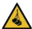
Risk of injury from suspended or unsecured load!
Damaged or insufficiently strong hoists and load slings can result in serious injury or even death.
→ Before use, therefore, check hoists and load slings for adequate load-bearing capacity and perfect condition. Secure the loads carefully. Never stand under suspended loads!
13.1.1 Transport by vehicle
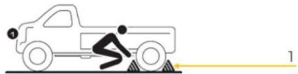
NOTE: To unload or load the machine on the truck, it must not be lifted with the boom.
natural_image
Simple line drawing of a person pushing a truck with a yellow line indicating speed (no text or symbols)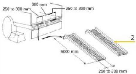
Loading with a ramp:
- Apply the parking brakes of the truck, and block (1) the drive wheels from both sides.
- Connect the ramps (2) directly to the cargo bed and secure them additionally with wheel chocks.
- Then slowly drive up the ramps with the machine.
- When the machine reaches the point between the ramps and the cargo bed, halt and then move very slowly until the machine reaches the horizontal position.
NOTE:
- No directional changes should be made when the machine is on the ramp. Should a change of direction be necessary, drive off the ramp completely and make the turn.
- Move the machine onto the cargo bed only with the arm completely pulled in. Otherwise the truck cabin could be damaged when swinging the upper carriage around.
- When driving forwards or backwards onto the cargo bed, or when swinging the upper carriage, make sure that neither the cabin nor the gates of the truck will be damaged.
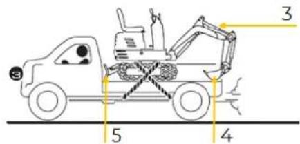
Securing on the cargo bed:
- After loading the machine onto the cargo bed, the upper carriage of the machine must be swivelled backwards (3).
- Lower the bucket (4) and the dozer (5) onto the loading platform.
NOTE: Never operate the machine from the ground, instead always operate it from the operator's seat.
• Block the crawlers and tie down the machine.
14 ASSEMBLY
14.1 Preparation
14.1.1 Checking delivery content
Check the delivery immediately for transport damage and missing parts. Report any damage or missing parts to your dealer or the shipping company immediately. Visible transport damage must also be noted immediately on the delivery note in accordance with the provisions of the warranty, otherwise the goods are deemed to have been properly accepted.
14.2 Pre-operation check
NOTE: Only carry out maintenance work on the machine when the engine is stopped, disconnected from the battery power supply and the machine is standing on level ground.
Before operating the machine or starting the engine, check the following points:
- Check screws for tightness
• Check the machine for oil leaks - Check that all switches, lamps etc. are working properly.
- Check that the working equipment and hydraulic components are functioning properly and are well greased.
-
Check the fill level of the fuel tank
-
Check engine oil level
- Check hydraulic oil level
15 OPERATION
Only operate the machine when it is in a perfect condition. Before each operation, a visual inspection of the machine must be carried out. Safety devices and operating elements must be checked carefully. Check screw connections for damage and tight fit.
15.1 Information on Initial Start-up
15.1.1 Notes for the first 50 operating hours
To optimise the life expectancy of the machine, the following points should be observed:
- Do not work at maximum speed and workload.
• Always work at the lowest possible speed. - Let the engine warm up sufficiently at low temperatures.
- Change the engine oil after the first few hours of operation.
15.2 Operating instructions
- Before starting the engine, ensure that there are no other persons in the immediate vicinity of the machine.
- Before operating the machine, check the travelling direction of the undercarriage. (Front idler and dozer are at the front of the machine).
- Avoid driving on a slope and working crossways to the slope.
- Do not try to break concrete or rocks by swinging the bucket sideways.
• Also avoid swinging the bucket sideways to move piles of soil. - The following must be strictly avoided under all circumstances:
• Excavation using the gravitational impact of the machine.
- Compacting of gravel or soil using the dropping action of the bucket.
• Excavation using the travelling power of the machine.
• The soil adhering to the bucket must not be removed as described in the following explanation:
- Adhering soil can be shaken off when the bucket is being emptied by moving the bucket out to the maximum stroke of the cylinder. Should this not suffice, swing out the arm as far as possible and operate the bucket back and forth.
- Do not hit the dozer with the boom cylinder! Make sure that the boom cylinder does not hit the dozer when carrying out deep excavation. If necessary swivel the upper structure so that the dozer is at the back of the machine.
- Pay attention when pulling in the bucket! When pulling in the bucket (for driving or transportation) avoid hitting the dozer.
- Avoid collisions! When moving the machine, pay attention so that the dozer does not collide with obstructions such as boulders etc. Such impact loads shorten the life of the dozer as well as the cylinder.
- Support the machine correctly! When stabilizing the machine with the dozer, lower the dozer fully on to the ground.
- If the water or mud level reaches higher than the top of the crawlers, the swivel bearing, swivel motor gear and ring gear may be exposed to mud, water and other foreign objects.
- The machine must be properly pressure washed after each use. Thoroughly clean the area around the swivel bearing, swivel motor gear and ring gear to remove foreign objects.
15.3 Operation
15.3.1 Starting the engine
Do not start the engine until all routine maintenance has been performed.
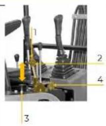
NOTE: Before starting the engine, all control levers must be in neutral position.
- Switch on the power supply with the battery disconnect switch
- Push the lock knob (1) and set the throttle lever (2) to "half throttle" (= middle position between "fast" and "slow").
- Pull out the throttle switch (3)
- Insert the ignition key (4) into the ignition lock and turn to the "ON" position until the engine is running.
- Push in the throttle switch (3)
Worming up the machine at low temperatures
The engine is difficult to start at low temperatures. On the one hand, the fuel can freeze and on the other hand, the viscosity of the hydraulic oil can increase. For this reason, the choice of fuel (summer or winter diesel) should depend on the ambient temperature.
NOTE: If the temperature of the hydraulic oil is below 25°C, the machine must be warmed up before use.
- Set the throttle so that the engine runs at medium speed. The bucket should be moved slowly forwards and backwards for 5 minutes.
NOTE: Do not operate any controls other than the bucket.
- Set the throttle so that the engine runs at high speed. The boom, arm and bucket should be set in motion for 5-10 minutes.
NOTE: Only operate the boom, arm and bucket. Do not drive or swivel the machine.
- The individual actions should be carried out several times to warm up the machine and ensure that it is ready for operation.
15.3.2 Stopping the engine
NOTE: Bucket and other attachments, as well as the dozer, must be lowered to the ground to prevent serious accidents. To cool down, the engine should continue to run at idle for approx. 2-3 minutes.
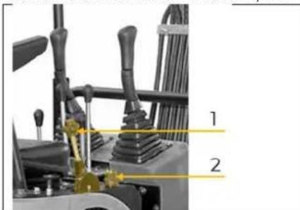
- Set the throttle lever to position "STOP"
- Set the ignition key (1) to the "OFF" position and remove it.
- Disconnect the machine from the battery power supply with the battery disconnect switch
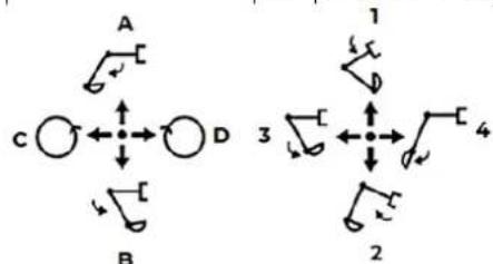
15.3.3 Functionality of the control levers of the attachments Overview of the function of the control levers of the attachments
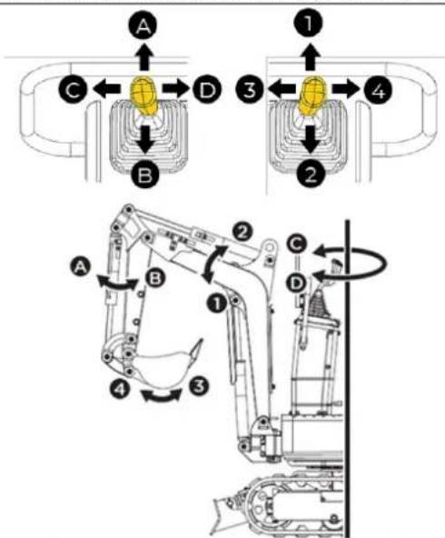
| Lever position | Direction of movement | |
| Operating le-ver left | A | Extend arm |
| B | Retract arm | |
| C | Swivel to the left | |
| D | Swivel to the right | |
| Operating le-ver right | 1 | Lower boom |
| 2 | Raise boom | |
| 3 | Pull in bucket | |
| 4 | Extend bucket | |
flowchart
graph TD
    A["A"] --> B["B"]
    C["C"] --> D["D"]
    style A fill:#f9f,stroke:#333
    style B fill:#ccf,stroke:#333
    style C fill:#cfc,stroke:#333
    style D fill:#fcc,stroke:#333
    subgraph Path 1
        1 --> 2
        2 --> 3
        3 --> 4
    end
    subgraph Path 2
        1 --> 2
        2 --> 3
        3 --> 4
    end
Operating of the boom
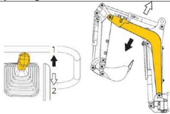
- To raise the boom, the right control lever for attachments must be moved to the rear (2). - To lower the boom, the right operating lever for attachments must be moved forward (1).
NOTE: When lowering the boom, make sure that the boom itself and the teeth of the bucket do not come into contact with the dozer.
Operating of the arm
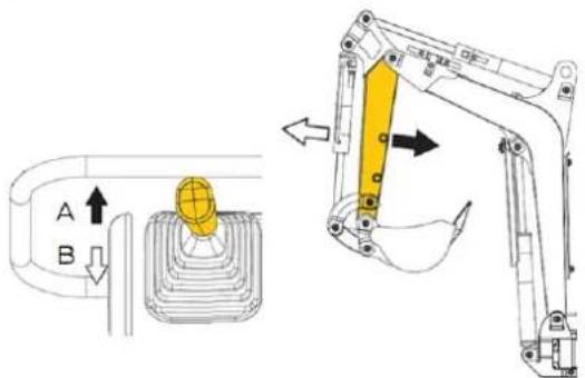
- The arm is extended by moving the left operating lever for attachments forward (A). - To retract the arm, move the left attachment control lever to the rear (B).
Operating of the bucket
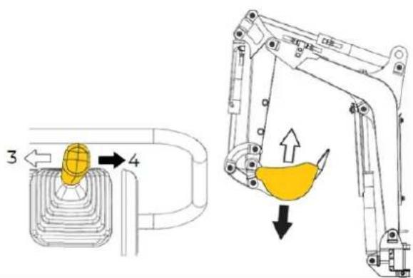
- To dig with the bucket, move the right attachment control lever from its neutral position to the left (3). - To empty the contents of the bucket, move the right attachment control lever to the right (4).
Swivel upper carriage
NOTE: Always inform work colleagues in advance what you are doing. Keep people out of the work area.
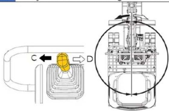
Do not abruptly operate the control lever of the left attachment from right to left (or reverse). Due to the law of inertia, this will result in an impulsive load on the swivel gear and the swivel motor. In addition, the service life of the machine will be shortened.
- If the left operating lever for attachments is moved to the left (C), the upper carriage swivels to the left. - If the left operating lever for attachments is moved to the right (D), the upper carriage swivels to the right.
Operation of the dozer
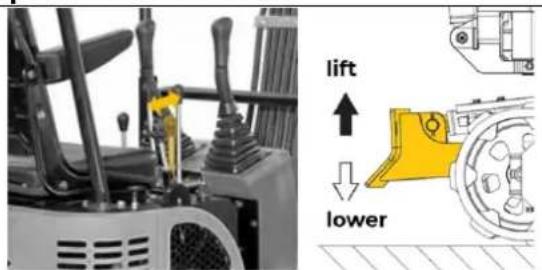
- To raise or lower the dozer, the operating lever must be moved to the rear or forward.
15.3.4 Move the machine
Driving
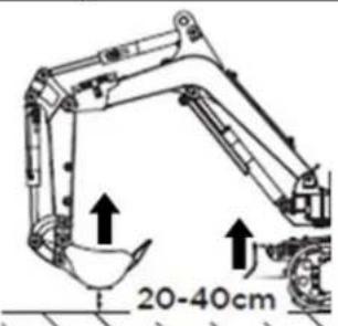
- Increase the engine speed from idle to a medium speed. - Raise the dozer and hold the bucket approx. 20 – 40 cm above the ground.
Travel lever (left and right)
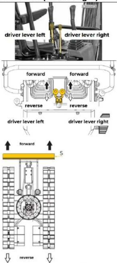
- By pressing the travel levers forward, the machine moves forward and reverse.
- The front of the machine corresponds to the position where the dozer (5) is located.
NOTE: If the upper carriage has been turned by 180°, i.e. the dozeris located "at the rear" from the operator's point of view, then the direction of travel is opposite to the operating direction of the levers (when the travel lever is operated forwards, the machine travels backwards from the operator's point of view).
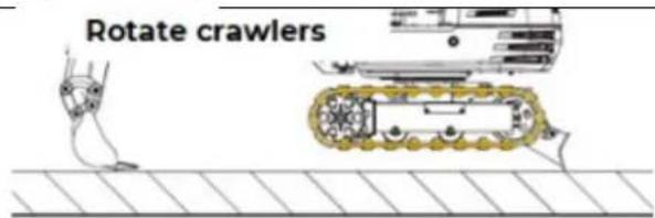
NOTE: When working on soft ground, if the crawler is dirty with sand or gravel, raise the crawler using the boom, arm and bucket. Then rotate the crawler to remove the sand and gravel.
15.3.5 Turns and changes of direction
WARNING:
- Do not change the direction of travel when driving on steep slopes. The machine could tip over.
- Watch out for people in the working area before changing direction.
NOTE: If the dozer is on the back of the machine, the direction of travel changes. For example, when the left (right) travel lever is pressed forward, the right (left) crawler moves backward, from the operator's point of view.
Pivot turn
| left rotation left rotation right rotation right rotation | ·If both travel levers are operated in opposite directions, both crawlers rotate at the same speed but in the opposite direction. The center of rotation is the center of the machine. |
Changing direction while standing
| ·By pressing the left travel lever forward, the machine turns to the right. | |
| ·If the left travel lever is moved to the rear, the machine turns to the left. |
Changing direction while driving
| neutral position forward travel | If the left travel lever is moved to the neutral position during travel, the machine turns to the left. |
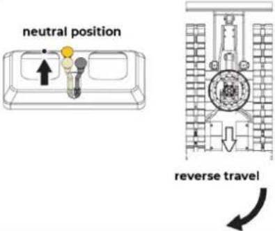 | • If the left travel lever is moved to the neutral position during reverse travel, the machine turns to the right. |
Uphill and downhill
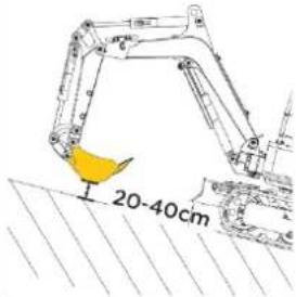 | Uphill driveWhen driving uphill, the lower edge of the bucket must be kept approx. 20-40 cm above the ground. | |
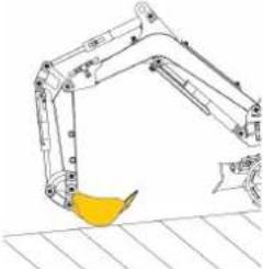 | DownhillAlthough the machine does not slip easily due to the crawlers, it is safer to let the bucket slide over the ground when driving downhill. Always choose a slow speed when driving uphill and downhill. |
Parking on the slope
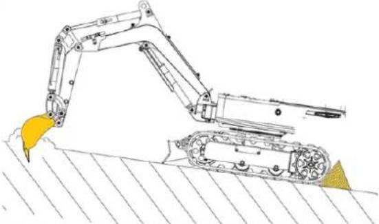 | WARNING:If the machine is parked on a slope or is not supervised, then the bucket must be lowered to the ground, all control levers must be put in neutral and the crawlers must be secured with brake wedges. |
Excavation
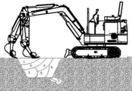 | Basis1. Before excavation, the arm cylinder should have angle with the arm as 90°, bucket with ground to be excavated as 30°. Only in such case, can each cylinder have the max excavating force.Tis setting is for relatively hard soil, so as to decrease the excavating resistance.2. To excavate any soft soil, bucket should be angled with the soil to be 60°, increasing the work efficiency. |
| Upper excavation | |
| Keep the bucket blade vertical to the ground, and retract the arm to start work. Excavating is carried out in 7 steps, as shown. | |
| Lower excavation Keep the angle between bucket base and the bevel at 30^ , and retract the arm to start wor |
16 CLEANING, MAINTENANCE, STORAGE, DISPOSAL
WARNING

No cleaning, upkeep, checks or maintenance when machine is running!
Shut off the machine and let it cool down before start servicing!
Disconnect the machine from the battery power supply with the battery disconnect switch!
NOTE: Before carrying out maintenance on the machine, place the machine on level, firm ground, lower the attachments to the ground, stop the engine and release the cylinder pressure by operating the levers.
When servicing hydraulic parts, ensure that the hydraulic oil has cooled sufficiently to avoid burns.
Prevent unintentional starting of the machine by turning the key to the "OFF" position. Remove the key.
16.1 Cleaning
Regular cleaning guarantees the long service life of your machine and is a prerequisite for its safe operation.
NOTE

The usage of certain solutions containing ingredients damaging metal surfaces as well as the use of scrubbing agents will damage the machine surface!
Clean the machine surface with a wet cloth soaked in a mild solution.
Never use running water or a high pressure cleaner to clean the machine.
Clean the machine daily after finishing work. Do not clean the machine while the engine is running. Water can enter the air filter and damage the engine. Take care to keep the air filter dry.
16.2 Maintenance
The machine is low-maintenance and only a few parts need to be serviced. Malfunctions or defects that could affect your safety must be repaired immediately!
- Before each operation, check the perfect condition of the safety devices.
- Regularly check the perfect and legible condition of the warning and safety labels of the machine.
- Use only proper and suitable tools.
- Use only original spare parts recommended by the manufacturer.
16.2.1 Maintenance plan
The type and degree of machine wear depends to a large extent on the operating conditions. The following intervals apply when the machine is used within the technical limits. The maintenance intervals may be shorter in special conditions!
| Components | Action | Operation hours (OH*) | |||||||||||||||
| 10 | 50 | 100 | 150 | 200 | 250 | 300 | 350 | 400 | 450 | 500 | 550 | 600 | 1000 | 2000 | |||
| Bucket theeth | Check daily | ||||||||||||||||
| Bolts, nuts | Check | initial start - up, every 50 OH | every 50 OH | ||||||||||||||
| Fuel Check | daily, every 10 OH | ||||||||||||||||
| Engine oil | Check | daily, every 10 OH | |||||||||||||||
| Change | x | x | x | x | x | x | x | x | x | every 100 OH | |||||||
| Engine oil-filter | Change | x | x | x | every 500 OH | ||||||||||||
| Hydraulic - oil | Check | daily, every 10 OH | |||||||||||||||
| Change | x | every 2000 OH | |||||||||||||||
| Work equipment pins | Check | daily, every 10 OH | |||||||||||||||
| Hydraulic hose and pipes | Check | daily, every 10 OH | |||||||||||||||
| Lubrication points | Check daily | ||||||||||||||||
| Machine Clean daily | |||||||||||||||||
| Battery Check | x | x | x | x | every 200 OH | ||||||||||||
| Track Check | x | x | every 500 OH | ||||||||||||||
| Tensioner | Maintenance | x | every 1000 OH | ||||||||||||||
| Greasing of slewing bearing gears | Check | x | x | x | x | x | x | x | every 100 OH | ||||||||
| Diesel-filter | |||||||||||||||||
| Change | x | x x | every 100 OH | ||||||||||||||
| External meshing gear of slewing bearing | Lubricating | x | x | every 500 OH | |||||||||||||
| Fuel hose and pipes | Check | x | x | x | x x | every 250 OH | |||||||||||
| Change | every 2 year | ||||||||||||||||
| Hydraulic oil suction filter | Change | x x | every 1000 OH | ||||||||||||||
* Operation hours = OH
Daily maintenance work
16.2.2 Check fuel tank level
WARNING

Never refuel if the engine is running. Smoking and open fire are prohibited during refuelling.
NOTE


Waste oils and fuel are toxic and must not be released into the environment!
Contact your local authorities for information on proper disposal.
WARNING: Danger of burns! Do not touch the muffler and the muffler pipe.
- Place the machine on a level ground
- Fold the seat forward
- Check the fuel tank level.
- Open the fuel filler cap and refuel. Make sure the fuel does not overflow.
NOTE: Make sure that no dirt, dust, water or other foreign objects get into the fuel system!
- Close the fuel filler cap tightly after refuelling.
- Fold the seat back
NOTE: Always refuel after the end of the workday.
16.2.3 Check the engine oil level
WARNING

Never refill engine oil if the engine is running.
NOTE


Waste oils and fuel are toxic and must not be released into the environment!
Contact your local authorities for information on proper disposal.
NOTES: Too low an engine oil level can cause engine damage.
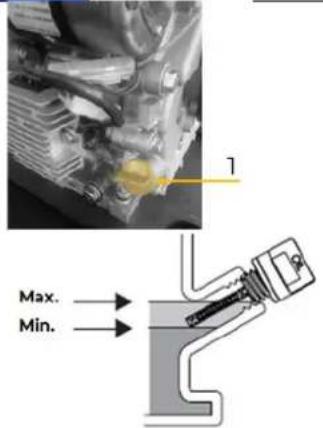
- To check the engine oil level, place the machine on a flat surface. Stop the engine and wait five minutes.
- Unscrew the oil dipstick (1) from the oil filler opening and wipe it with a clean, lint-free cloth or a non-linting paper towel.
• Reinsert the oil dipstick completely. - Remove the oil dipstick and check the oil level.
- If the engine oil level is between the two markings (min. / max.), there is no need to top up the engine oil.
- If the oil level is low, add new engine oil (for engine oil type and quantity, see technical data).
• If the level is correct, screw the oil dipstick back in.
16.2.4 Check the hydraulic oil level
WARNING: During operation, the hydraulic system can become very hot and pressurised. Do not start maintenance work until the machine has cooled down.
natural_image
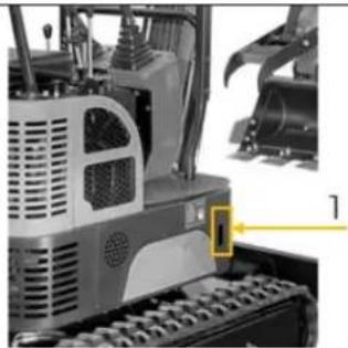
Close-up of a mechanical vehicle's front view showing engine, chassis, and gear components (no visible text or symbols)NOTE: Before refilling with new hydraulic oil, wipe off dirt and sand around the filler opening. Always use hydraulic oil of the identical type.
- Place the machine on a flat surface. Stop the engine and wait five minutes.
- Check the hydraulic oil level to verify that it is between the marks of the sight glass (1)
- If the hydraulic oil level is too low, sufficient hydraulic oil must be refilled via the hydraulic oil filler opening before starting the engine.
WARNING: The hydraulic oil tank has pressure. Slowly open the hydraulic oil cap to release the pressure before taking off the cap!.
• After refilling, close the cap and check the fill level again.
16.2.5 Check and maintenance hydraulic system
- Place the machine on a flat surface. Stop the engine and wait five minutes.
- During operation, the hydraulic system can become very hot and pressurised. Do not start maintenance work until the machine has cooled down.
- Drain the air out of hydraulic oil reservoir to release inside pressure.
WARNUNG: Inspection and maintenance of hot and pressure parts may cause them or hydraulic oil to spray out and leading to personal injury!
While removing the bolts or nuts, do not have your body facing them, as the hydraulic parts, even if they cools down, they may still have pressure.
- Never try to check the traveling or slewing motor circuits on slope, as they may have pressure due to their dead weight.
- While connecting the hydraulic hoses and pipeline, keep the seal surface free of any dirt and damage.
- Clean the hose, the pipes and inside of hydraulic oil tank with detergent, and then thoroughly dry them.
- Use the O-ring free of any damage or defect.
While connecting the pressure hose, do not twist it; otherwise its service span will be shortened.
o Carefully tighten the low-pressure hose clamp.
NOTE: The hydraulic oil to be added should have the identical type. Namely, do not mix the oil with different types. The hydraulic oil has been added before delivery, and therefore, please use the recommended oil. All oil in system should be changed at once.
- Nevere start up the machine without hydraulic oil!
16.2.6 Lubrication points
WARNING:
- First lower all attachments to the ground and stop the engine.
NOTE:
- Do not step on the bucket teeth while lubricating.
- When excavating in water, the following points should be lubricated. Lubricate again after finishing work.
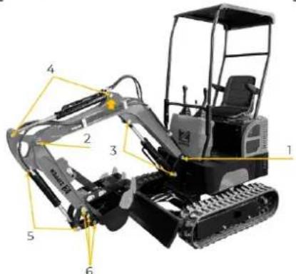
The lubrication points marked in the illustrations on the left must be lubricated.
(1) Boom bottom linkage
(2) Arm bottom linkage
(3) Boom cylinder boss
(4) Arm cylinder boss
(5) Bucket cylinder pin
(6) Bucket link pins
16.2.7 Check bucket teeth
Check if the bucket teeth are worn or loosened.
Worn beyond the service limit, the bucket teeth must be replaced:
- New: 190 mm
• Service limit: 130 mm
Maintenance work every 200 operation hours
(Simultaneously perform the maintenance work for 50 and 100 working hours at the same time)
16.2.8 Battery
NOTE:
- Do not smoke when working on the battery. Keep the battery away from naked flames and sparks. Oxyhydrogen gas produced when charging the battery is explosive.
- Always wear eye protection and gloves when working with the battery! Electrolyte is toxic! Contact can cause burns to the skin or clothing or blindness if it comes into contact with the eyes.
• Care must be taken not to spray out the electrolyte.
Procedure - Checking the poles and the electrolyte level:
- When removing the battery, always disconnect the earth cable from the negative terminal (-) first. When installing the battery, proceed in reverse.
- Always keep the terminals at top to battery and the breather clean, to avoid the battery from discharging..
- Check if the battery terminal is loosened or rusted. Coat the terminals with battery terminal grease to avoid any corrosion.
Replace the battery:
As soon as the battery can no longer be charged or no more power can be stored, it must be replaced.
When replacing an old battery with a new one, only use batteries of the same specification.
16.2.9 Replace the fuse
natural_image
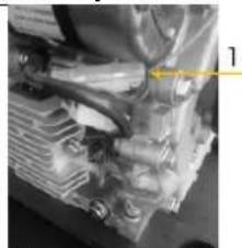
Close-up of mechanical components with a yellow arrow pointing to a specific part (no visible text or symbols)If the machine does not work, firstly check the fuse Install the fuse with correct amperage, so as to prevent against burning of electrical system due to overloading!
Maintenance work every 250 operation hours
(Simultaneously perform the maintenance work for 50, 100, 150 and 250 working hours at the same time)
16.2.10 Check hydraulic hose and pipes
natural_image
Abstract black-and-white illustration of hands holding a book and a plant (no text or symbols)WARNING:
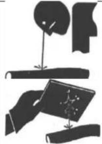
- Hydraulic oil can penetrate the tissue under the skin and lead to personal injury!
• Therefore use a piece of cardboard to check for leaks. - Wear safety goggles.
- Ensure that you keep your hands and body at a safe distance from hydraulic components that is under pressure..
- Should an accident occur, seek medical attention immediately. Oil on the skin must be removed immediately otherwise it can lead to injury.
- Leaked hydraulic oil and lubricant can result in a fire and personal injury!!
- Place the machine on a flat surface.
- Stop the engine.
- Remove the key.
- Check following:
- The condition of the components
o whether components are missing,
o whether hose clamps have come loose,
o whether hoses are twisted, and
o whether pipes or hoses are rubbing against each other.
Daily check:
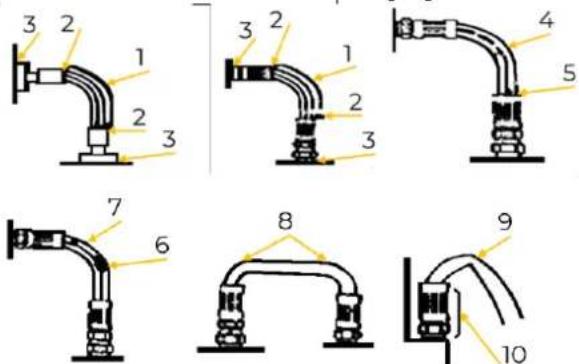
| Components | Trouble | Solution |
| Hose surface | Leakage (1) | replace |
| Hose end | Leakage (2) | replace |
| Connection | Leakage (3) | Tighten, replace the hose or use a new O-ring |
Every 250 operation hours:
| Components | Trouble | Solution |
| Hose surface | Crack (4) | replace |
| Hose end | Crack (5) | replace |
| Hose surface | Reinforcing material protruded (6) | replace |
| Hose surface | Local part protruded (7) | replace |
| Hose | Bend (8) | replace |
| Hose | Bend (9) | Modify (correct bending radius) |
| Hose end or connection | Deformation or corrosion (10) | replace |
NOTE:
- Do not bend or impact any pressure pipes.
o Never install any bent or damaged hose or pipe.
16.2.11 Check the bolts and nuts for tightening torque
(Initial start - up, every 50 OH, then at interval of every 250 OH)
If needed, retighten with the set torque (see following tables).
NOTE: Use the torque wrench to check the torques of bolts and nuts!!
| metric bolts and nuts | |||
| Thread dimensions | Standard torque (Nm) | Thread dimensions | Standard torque (Nm) |
| M6 | 12±3 | M14 | 160±30 |
| M8 | 28±7 | M16 | 240±40 |
| M10 | 55±10 | M20 | 460±60 |
| M12 | 100±20 | M30 | 1600±200 |
| torque (Nm) of main components | |||
| Thread dimensions | Recommended torque (Nm) | ||
| M16 bolts fixing the traveling motor | 252±39.2 | ||
| M16 bolts fixing the sprocket | 252±39.2 | ||
| M20 bolts fixing the slewing bearing | 570±60 | ||
| M20 bolts fixing the swing mechanism | 570±60 | ||
NOTE:
• Before installed, the bolts and nuts should be cleaned.
- Grease the bolts and the nuts, so as to stabilize their abrasion coefficient.
• The counterweight bolts should be kept tightened up
Maintenance work every 500 operation hours
(Simultaneously perform the maintenance work for 50, 100, 150, 250 and 500 working hours at the same time)
16.2.12 Lubrication of external meshing gear of slewing bearing
natural_image
Close-up of a tracked excavator with visible blade and handle, no text or symbols present- To check the engine oil level, place the machine on a flat surface.
- Stop the engine and wait five minutes.
- Remove the key.
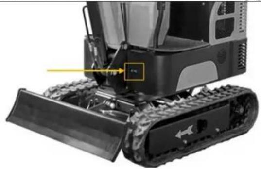
- The grease has to be stored on the top of external meshing gear of slewing bearing, free of any pollution. Add approximate 0.5kg of grease if needed
- Any polluted grease should be replaced with new one.
16.2.13 Engine oil and filter element change
NOTE


Waste oils and fuel are toxic and must not be released into the environment!
Contact your local authorities for information on proper disposal.
NOTE: Before changing the engine oil, first stop the engine and wait until the engine oil has cooled down.
- Place the machine on a flat surface.
- Stop the engine nd wait five minutes
- Remove the key.
- Set the battery disconnect switch to position „OFF“
natural_image
Close-up mechanical component with numbered annotations (1 and 2) highlighting a highlighted section, no readable text or symbols present.Drain engine oil:
- Choose a sealable and generously sized container to prevent engine oil from getting into the environment.t.
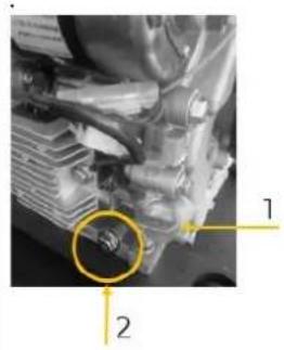
- Open the oil drain plug (2) on the underside of the engine and drain all the engine oil.
- Then refit the oil drain plug.
- Take off the screws fixing the engine oil filter elements with a screw-driver to take the filter element out.
- Reinstall the new filter and tighten the screws fixing the new element with a screwdriver.
Refill engine oil:
• Unscrew the oil dipstick (2) and fill fresh engine oil into the oil filler opening.
- Wipe away oil residues with a cloth.
- Close the oil filler opening again with the oil dipstick and tighten.
Check engine oil level:
• After 15 min check the engine oil level.
16.2.14 Check fuel line
- Check that all lines and hose clamps are tight and not damaged.
- If lines or hose clamps are worn or damaged, they must be replaced or repaired immediately.
Maintenance work every 2000 operation hours
(Simultaneously perform the maintenance work for 50, 100, 150, 250 and 500 working hours at the same time)
16.2.15 Hydraulic oil and oil suction filter change
Change of the oil suction filter every 1000 OH.
WARNING: During operation, the hydraulic system can become very hot and pressurised. Do not start maintenance work until the machine has cooled down.
Change hydraulic oil:
- Place the machine on a flat surface.
- Lower the attachments to the ground. Completely retract the arm cylinder and extend out the bucket cylinder, so as to locate the machine.
- Lower the bucket onto the ground.
- Idle engine at low speed for 5 min.
- Remove the key.
- Set the battery disconnect switch to position „OFF“
• Always use hydraulic oil of the identical type. - Remove the cover.
NOTE: Before refilling with new hydraulic oil, wipe off dirt and sand around the filler opening.
- Slowly open the hydraulic oil cap.
WARNING: The hydraulic oil tank has pressure. Slowly open the hydraulic oil cap to release the pressure before taking off the cap.
- Loosen and remove the cap for the oil suction filter element
- Loosen and remove the drain plug in the bottom of the hydraulic oil tank to drain the tank of hydraulic oil.
- Remove the oil suction filter.
• Use an oil collecting pump to suck the oil remnants out of the bottom of the hydraulic oil tank - Clean the suction filter.
- Refit the filter and ensure that the filter is correctly secured to the outlet.
- Clean and refit the drain plug in the bottom of the tank.
- Refill the hydraulic oil to a level between the marks of the sight glass.
- Fit the cap to the oil suction filter element to ensure that the filteris in the correct position and then tighten the bolts to 49 Nm.
NOTE: Nevere start up the machine without hydraulic oil it causes damage of the hydraulic pump!
- Tighten the oil tank cap.
- With engine idling at low speed, slowly and steadily control the lever for 15 min to drain the air out of hydraulic system.
- Completely retract the arm cylinder and extend out the bucket cylinder, so as to locate the machine.
- Lower the bucket to the ground.
- Stop the enginge and remove the key.
- Check the hydraulic oil level and add if necessary.
Maintenance work every year
16.2.16 Electrical wiring and fuses
- Check all electrical connections regularly for proper contact. Loose or damaged wiring can cause electrical system malfunctions, such as: Short circuit, leakage current or other costly defects.
- Check wiring and replace damaged components immediately.
- If a fuse is blown shortly after replacement, contact your nearest dealer. Always use fuses of the same specification.
Biennial maintenance
16.2.17 Fuel hose
- Change fuel hose and hose clamps.
16.2.18 Change bucket
NOTE:
- If equipment replacement must be performed with the motor running, always work in pairs. One person sits at the driver's seat and the other person works on the machine.
- Do not use your fingers to centre the holes. There is a risk of injury in the event of an uncontrolled, sudden movement!
- Read the operating instructions of the attachment to ensure correct operation.
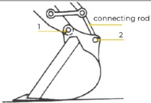
Procedure:
- Place the machine on a flat surface.
- Lower the bucket's flat surface onto the ground to ensure that the bucket cannot move when the bucket pins are removed.
- Slide the lock-rings out.
- Remove the bucket pins (1) and (2) to se parate the bucket and the arm.
NOTE: Chips may fall off when installing or removing the connecting bolts. Always wear gloves, eye protection and a helmet.
- Clean the bucket pin and its pin hole and then properly grease them.
- Adjust the arm and the new bucket correctly, and make sure the bucket does not roll away.
- Install the bucket pins (1) and (2) and insert the lock ring and washer on bucker pin (1) and (2).
- Adjust the bucket's connection distance at pin (1).
- Lubricate bucket pin (1) and (2).
- Start the engine and allow it to operate at low speed. Slowly turn the bucket in two directions to check that nothing interferes with the bucket's movement.
- Any faults that occur must be repaired immediately.
16.3 Maintenance in special conditions
| Operational conditions | Precautions for maintenance |
| peat soil, rain or snow | Before operation, check all the drain plugs are tightened.After operation, clean machine and check bolts and nuts for break, damage, looseness or loss.Lubricate all parts to be lubricated on time. |
| sandy environments | Before operation, check all the drain plugs are tightened.After work, thoroughly clean the clean to remove the salt.Frequently maintain the electrical system from being corroded. |
| dusty environments | Air filter: clean the filter element at regular intervals, checking after medium-long periods or shorter periods of time.Radiator: clean the oil cooler screen to avoid any blockage.Fuel system: clean the filter at regular intervals, checking after medium-long periods or shorter periods of time.Electrical devices: clean at regular intervals, especially the generator and starter. |
| stony roads | Tracks: Careful operation. Check frequently the bolts and nuts to ensure that are not broken, damaged or missing. Loosen the track a little more than normally.Boom tools: Parts can become damaged on stony roads. Therefore use a reinforced or very robust bucket. |
| freezing cold | Fuel: Use high-quality fuel that is suitable to use in low temperatures.Lubricant: Hydraulic oil and engine oil are suitable for use in icy conditions.Battery: Keep the battery fully charged and carry out maintenance on the battery more frequently. The electrolyte can freeze if the battery is not fully charged.Tracks: Keep the tracks clean. Park the machine on a flat surface to avoid the tracks freezing |
| falling stones | Roof above the operator seat: Add protection to the roof above the operator seat if necessary to prevent the machine becoming damaged from falling stones. |
16.4 Work steps after the work has been carried out
- Thoroughly clean and wipe the machine dry after finishing work. Otherwise, mud and soil may freeze on the chains at low temperatures. Then the operation of the machine is no longer possible.
- Wipe the cylinder rods of the machine dry. Otherwise, dirty water may seep through the seals.
16.5 Storage
In case of prolonged storage, proceed as follows:
- Clean the machine and store the machine in a dry, frost-proof and lockable place when not in use. Make sure that unauthorised persons and especially children do not have access to the machine.
- If the machine has to be kept outdoors, lay out wooden planks on even ground, place the machine on the planks and cover it completely.
- Do an oil change and grease the machine.
• Heavily grease the visible sections of the piston rods.
- Remove the battery and store indoors.
- If the storage period is longer than one month: Switch on the engine and operate the attachments and the driving mechanism without load so that the hydraulic oil can circulate. In addition, wipe grease from the cylinder rods. This procedure should be repeated monthly.
NOTE:
- Do not clean the machine while the engine is running. If the machine is cleaned while the engine is running, water may get into the air filter and cause engine malfunctions. Therefore, wash the machine carefully so that no water splashes onto the air filter.
- To avoid the danger of exhaust fume poisoning, do not operate the engine in a closed building without proper ventilation.
- When storing the machine, remove the key from the starter switch to avoid unauthorized persons from operating the machine and getting injured.
Important notes on storing the battery to avoid possible damage:
If the machine will not be used for a longer period of time, the battery should be disconnected and, if possible, disassembled from the machine. Before storage, the battery should be charged again. Batteries should be stored at room temperature (approx. 20^ C) in a dry and frost-proof place. Avoid large temperature fluctuations (e.g. do not expose battery to direct sunlight or store near heating systems). Higher temperatures can lead to accelerated ageing and premature loss of function of the battery. If the battery is not used for a longer period of time, check the charge level regularly (monthly, max. every 3 months). If necessary, recharge the battery.
Procedure after a longer storage period:
- Wipe off the grease from the hydraulic cylinder rods.
- Turn on the engine and activate the attachments and the drive mechanisms without load in order to circulate the hydraulic oil (If the machine is stored for longer than one month, perform steps (1) and (2) once every month).
NOTE

Improper storage can damage and destroy important components. Only store packed or already unpacked parts under the intended ambient conditions!
16.6 Disposal
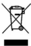
Observe the national waste disposal regulations. Never dispose of the machine, machine components or operating equipment in the residual waste. If necessary, contact your local authorities for information regarding available disposal options.
If you purchase a new machine or equivalent equipment from your specialist dealer, he is obliged in certain countries to dispose of your old machine properly.
17 TROUBLESHOOTING
WARNUNG

Hot surfaces and rotating machine parts while the engine is running can cause serious injury or even death
Always stop the machine before carrying out troubleshooting work, let it cool down and secure it against unintentional restarting
If you are unable to carry out the necessary repairs properly and/or do not have the required training, always consult a specialist to solve the problem.
Hydraulic
| Symptom | Possible cause | Solution |
| The machine does not move | Low oil level in the hydraulic tank, the hydraulic pump cannot suck the oil up. | Add hydraulic oil |
| Oil filter is blocked | Change the filter and clean the system | |
| Engine clutch is damaged (plastic plate, elastic plate) | Repair / change | |
| Hydraulic pump damaged | Repair / change | |
| Safety valve is set for to low pressure or is stuck. | Adjust the correct pressure => Pressure does not increase, disassemble and clean valve. If the spring is worn, add a washer or replace the spring | |
| One of the tracks do not move | Main pump that supplies pressure to the tracks is damaged. | Repair / change |
| Main valve stem is blocked and the spring is damaged | Repair / change | |
| Engine is damaged | Repair / change | |
| Bushing is damaged | Repair / clean | |
| The machine moves slowly or powerless | Low oil level in the hydraulic tank | Add hydraulic oil |
| Low engine rpm | Adjust engine rpm | |
| Low pressure in the system safety valve | Adjust to the specified pressure. | |
| Leak inside the main pump | Repair / change | |
| Hydraulic oil filter / insert is blocked | Clean / change | |
| Boom (bucket arm and bucket) moves only in one direction | Main valves are stuck or the valve stem spring is damaged | Repair / change |
| Boom (bucket arm and bucket) does not move | Boom valve stem is stuck or has low overload pressure | Repair / change |
| Fuel pipe is leaking, is torn off, the O-ring is damaged or the pipe fitting is loose | Repair / change | |
| Dirt in the main valve | Repair / change | |
| Boom (bucket arm and bucket) falls too quickly or the cylinder falls at a certain height even though it is not operated, due to own weight | Low overload pressure in the valve. | Adjust |
| Internal leak in the cylinder | Repair / change | |
| Hot hydraulic oil.Slewing drive and attachment react with a delay and weakly | Incorrect quality of hydraulic oil | Change the hydraulic oil and fill with the recommended hydraulic oil |
| Surface of the hydraulic cooler contaminated with oil and dirt => air slot blocked | Clean | |
| Low oil level in the hydraulic tank | Add hydraulic oil | |
| Hydraulic components such as motor, main valve and oil cylinder or sealing components are seriously worn and cause internal leak, which increases the oil temperature. Safety valve is leaking => leads to overflow | Change the components in time | |
| Indifferent left and right slewing speed | Right and left rotation of multi-way valve have different overloaded pressure | Adjust |
| Rotation valve rod of multi-way valve is slightly stuck | Adjust the screws on the top and bottom of the valves. | |
| No or self-acting slewing | Serious external leak of hydraulic oil pipe | Change pipe fitting and sealing components |
| Low overloaded pressure for rotation of multi-way valv | Adjust | |
| Serious internal leak of slewing motor | Repair / change | |
| The slewing mechanism moves even when not actuated | Main valve stem spring is damaged | Change |
| The machine makes abnormal noise and shakes during operation | Low oil level in the hydraulic tank | Add hydraulic oil |
| Safety valve of multi-way valve makes noise | Adjust | |
| Blocked filter | Clean / change | |
| Uneven engine rpm | Wenden Sie sich an den Lieferanten | |
| Powerless hydraulic cylinder | Damaged sealing components | Change |
| A groove is found on the piston rod due to abrasion or detachment of chromium | Repair / change | |
| coating of piston rod, which causes oil leak | ||
| • Air in the cylinder causes shaking noise during operation | • Vent the cylinder | |
| Engine | ||
| Symptom | Possible cause | Solution |
| fuel pump does not supply fuel or supply less fuel | • Pump fault | • Repair / change |
| • Less fuel level in the tank | • Add fuel | |
| • Fuel hose/pipe is damaged | • Change | |
| Engine fails to start | • Low battery | • Charge the battery |
| • Battery terminal is corroded or loose | • Clean battery terminals, tighten and coat with battery terminal grease | |
| • Starter does not operate | • Repair / change | |
| • Ignition lock damaged | • Repair / change | |
| • Less fuel level in the tank | • Check fuel level and refill if necessary | |
| • Fault in the fuel supply system | • Check pipeline of fuel supply system, fuel filter and fuel pump; change blocked and damaged assembly if necessary to ensure unobstructed fuel supply | |
| • Air, water or foreign matter block the fuel system | • Vent fuel system | |
| • Fuel pump fault | • Repair / change | |
| • Engine fault | • Check and repair | |
| Engine stops suddenly | • Less fuel level in the tank | • Add fuel |
| Mechanic | ||
| Symptom | Possible cause | Solution |
| Noisy structural components | • Loose fasteners | • Check and tighten |
| • Aggravated abrasion between bucket and end face of bucket rod | • Adjust less clearence | |
| Bucket teeth have dropped during operation | • Deformed spring and weakened elasticity of bucket tooth pin | • Change bucket tooth pin |
| • Unmatched bucket tooth pin and seat | • Change bucket tooth pin | |
| Track has tangled up | • Loose track | • Adjust track tension |
| Track blocked | • Blocked through stones | • Remove stones |
| • Tight track | • Adjust track tension | |
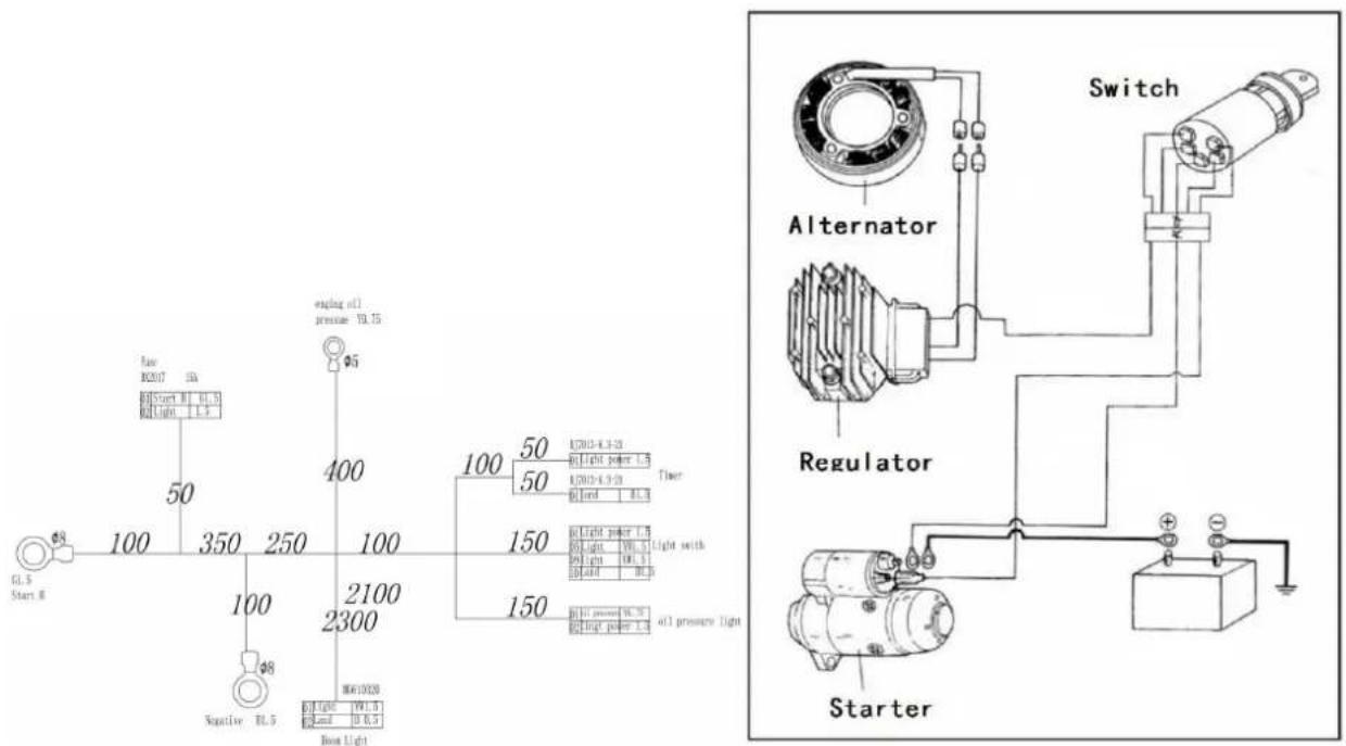
18 ELEKTRISCHER SCHALTPLAN / WIRING DIAGRAM
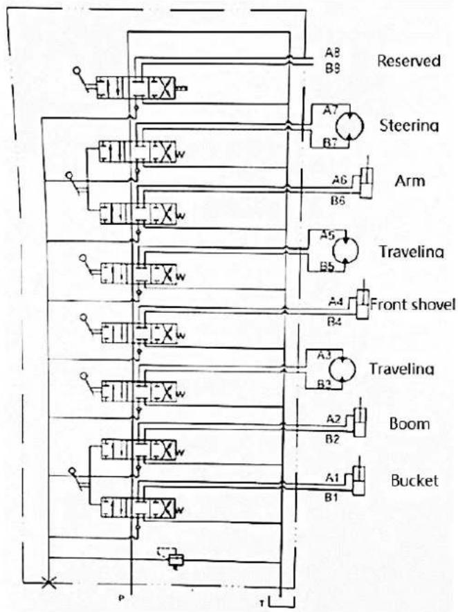
19 HYDRAULISCHER SCHALTPLAN / HYDRAULIC DIAGRAM
flowchart
graph TD
    A["Reserved"] --> B["A8"]
    A --> C["B9"]
    B --> D["Xw"]
    C --> E["A7"]
    D --> F["Xw"]
    E --> G["B7"]
    H["Steering"] --> I["A6"]
    J["Arm"] --> K["B6"]
    L["Traveling"] --> M["A5"]
    N["Front shovel"] --> O["B5"]
    P["Boom"] --> Q["A2"]
    R["Bucket"] --> S["B1"]
    T["P"] --> U["Xw"]
    V["T"] --> W["Xw"]
    X["Xw"] --> Y["A4"]
    Z["Xw"] --> AA["B4"]
    AB["A3"] --> AC["B3"]
    AD["A2"] --> AE["B2"]
20 ERSATZTEILE / SPARE PARTS
(EN) With original ZIPPER spare parts you use parts that are attuned to each other shorten the installation time and elongate your products lifespan.
NOTE

The installation of parts other than original spare parts leads to the loss of the guarantee! Therefore: When replacing components/parts, only use spare parts recommended by the manufacturer.
Order the spare parts directly on our homepage – category SPARE PARTS or contact our customer service
• via our Homepage – category SERVICE/NEWS - SPARE PARTS REQUEST,
• by e-mail to eg01@zipper-maschinen.at.
Always state the machine type, spare part number and designation. To prevent misunderstandings, we recommend that you add a copy of the spare parts drawing with the spare parts order, on which the required spare parts are clearly marked, especially when not using the online-spare-part catalogue.
BOM of vehicle parts
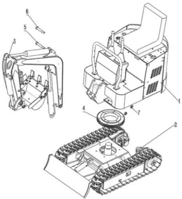
| # | Description | Qty | # | Description | Qty |
| 1 | Upper frame assembly | 1 | 5 | Connecting shaft between boom and upper frame | 1 |
| 2 | Lower frame assembly | 1 | 6 | Connecting shaft between boom and upper frame | 1 |
| 3 | Front work equipment assembly | 1 | 7 | Pivot sleeve | 2 |
| 4 | Slewing bearing assembly | 1 |
Lower frame
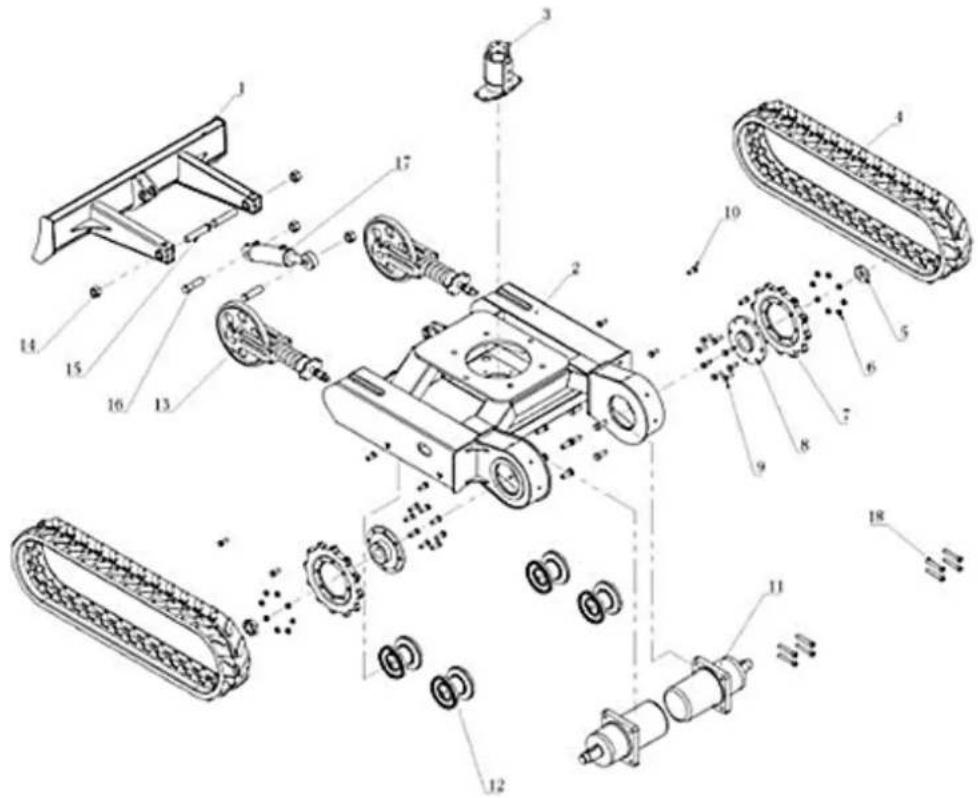
| # | Description | Qty | # | Description | Qty |
| 1 | Welded dozer shovel | 1 | 10 | Bolts fixing the track roller | 8 |
| 2 | Welded lower frame | 1 | 11 | Traveling motor | 2 |
| 3 | Slewing joint | 1 | 12 | Track roller | 4 |
| 4 | Rubber crawler | 2 | 13 | Idler assembly | 2 |
| 5 | Lock nut | 2 | 14 | Pivot nuts | 4 |
| 6 | Sprocket nuts | 16 | 15 | Connecting shaft of dozer shovel | 2 |
| 7 | Drive wheel | 2 | 16 | Connecting shaft of cylinder | 2 |
| 8 | Connecting disc | 2 | 17 | Cylinder of dozer shovel | 1 |
| 9 | Sprocket bolts | 16 | 18 | Bolts fixing idler assembly | 8 |
Upper frame
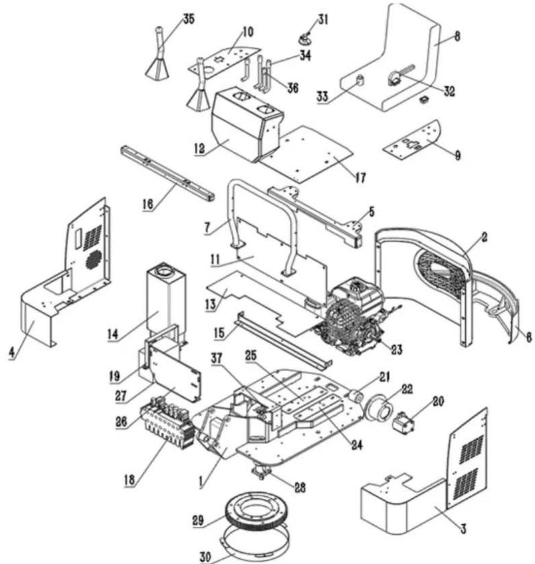
| # | Description | Qty | # | Description | Qty |
| 1 | Welded upper frame | 1 | 20 | Master cylinder | 1 |
| 2 | Covers of rear housing | 1 | 21 | Coupler | 1 |
| 3 | Covers of left housing | 1 | 22 | Pump disc | 1 |
| 4 | Covers of right housing | 1 | 23 | Engine | 1 |
| 5 | Welded inside support frame | 1 | 24 | Rear bracket base of engine | 1 |
| 6 | Rear counterweight plate | 1 set | 25 | Front bracket base of engine | 1 |
| 7 | Handrail | 1 | 26 | Main valve holder | 1 |
| 8 | The seat | 1 | 27 | Battery | 1 |
| 9 | Left- upper cover | 1 | 28 | Rotary motor | 1 |
| 10 | Right - upper cover | 1 | 29 | Slewing bearing | 1 |
| 11 | L- shaped covers | 1 | 30 | Dust cover | 1 |
| 12 | Console | 1 | 31 | Main power switch | 1 |
| 13 | Pedal | 1 | 32 | Manual accelerator | 1 |
| 14 | Hydraulic oil tank | 1 | 33 | Key starter | 1 |
| 15 | The front of the bracket A | 1 | 34 | Traveling handle | 2 |
| 16 | The front of the bracket B | 1 | 35 | Work handle | 2 |
| 17 | The seat plate | 1 | 36 | Front shovel handle | 1 |
| 18 | multi-way valve | 1 | 37 | Slewing joint pallet | 1 |
| 19 | Battery platen | 1 |
Front work equipment
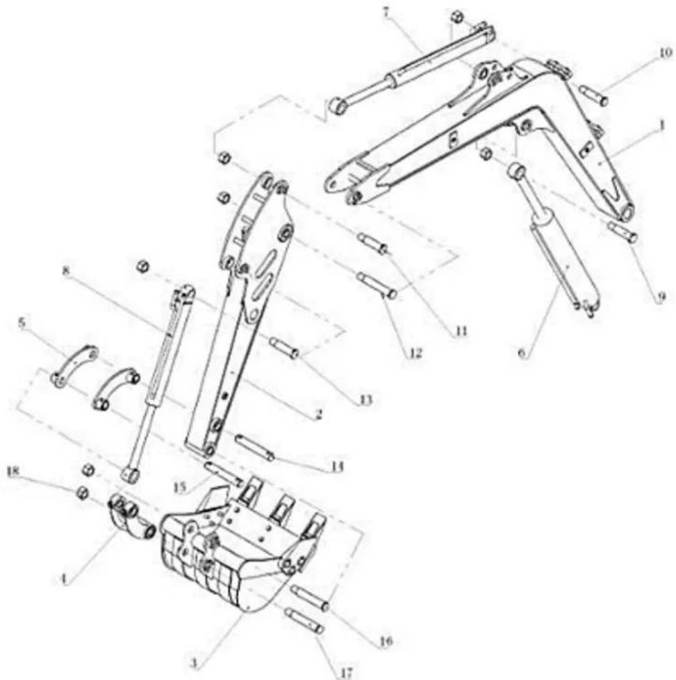
| # | Description | Qty | # | Description | Qty |
| 1 | Boom | 1 | 10 | Rear shaft of arm cylinder | 1 |
| 2 | Arm | 1 | 11 | Front shaft of arm cylinder | 1 |
| 3 | Bucket | 1 | 12 | Front shaft of boom | 1 |
| 4 | Connecting rod | 1 | 13 | Rear shaft of bucket cylinder | 1 |
| 5 | Push rod | 1 | 14 | Medium shaft of arm | 1 |
| 6 | Boom cylinder | 1 | 15 | Front shaft of bucket cylinder | 1 |
| 7 | Arm cylinder | 1 | 16 | Front shaft of arm | 1 |
| 8 | Bucket cylinder | 1 | 17 | Connecting shaft between bucket and connecting rod | 7 |
| 9 | Medium shaft of boom | 1 | 18 | Shaft locker sleeve | 1 |
Traveling motor
![41a/41b 22 27 11 10 12 13 9 7 17 8 6 5 2 16 17 14 985 cm³/r [60.0 in³/r] Displ. has split Geroler ring. seals not included in seal kit Shuttle (Two Way) Shuttle Valve Location when Applicable 39 51 52 29 21 14 15 16 17 16 20 1 1 26 19 34 3 18 4 3 18 3 23 28 3 53 39](/content/2026/05/855616/images/5194d3868864dedfb00af69cafa36354bf3e8fc0d9a0a3142e72aed808b52158.jpg)
ZIPPER machines are subject to the legal warranty, which is valid in the current version. (For electrical and mechanical components, this is equivalent to 2 years (excluding wearing parts and batteries), starting from the date of purchase by the end user/buyer. For rechargeable batteries and batteries, the legal warranty of 6 months applies, starting from the date of purchase by the end user/buyer). In case of defects during this period, which are not excluded by paragraph 3, ZIPPER will repair or replace the machine at its own discretion.
2.) Report:
In order to check the legitimacy of warranty claims, the final consumer must contact his dealer. The dealer has to report in written form the occurred defect to ZIPPER. If the warranty claim is legitimate, ZIPPER will pick up the defective machine from the dealer. Returned shippings by dealers which have not been coordinated with ZIPPER, will not be accepted and refused.
3.) Regulations:
a) Warranty claims will only be accepted, when a copy of the original invoice or cash voucher from the trading partner of ZIPPER is enclosed to the machine. The warranty claim expires if the accessories belonging to the machine are missing.
b) The warranty does not include free checking, maintenance, inspection or service works on the machine. Defects due to incorrect usage of the final consumer or his dealer will not be accepted as warranty claims either. Some examples: usage of wrong fuel, frost damages in water tanks, leaving fuel in the tank during the winter, etc.
c) Defects on wear parts are excluded, e.g. carbon brushes, collection bags, knives, cylinders, cutting blades, clutches, sealings, wheels, saw blades, splitting crosses, riving knives, riving knife extensions, hydraulic oils, oil/air/fuel filters, chains, spark plugs, sliding blocks, etc.
d) Also excluded are damages on the machine caused by incorrect or inappropriate usage, if it was used for a purpose which the machine is not supposed to, ignoring the user manual, force majeure, repairs or technical manipulations by not authorized workshops or by the customer himself, usage of non-original ZIPPER spare parts or accessories.
e) After inspection by our qualified personnel, resulted costs (like freight charges) and expenses for not legitimated warranty claims will be charged to the final customer or dealer.
f) In case of defective machines outside the warranty period, we will only repair after advance payment or dealer's invoice according to the cost estimate (incl. freight costs) of ZIPPER.
g) Warranty claims can only be granted for customers of an authorized ZIPPER dealer who directly purchased the machine from ZIPPER. These claims are not transferable in case of multiple sales of the machine.
4.) Claims for compensation and other liabilities:
The liability of company ZIPPER is limited to the value of goods in all cases. Claims for compensation because of poor performance, lacks, damages or loss of earnings due to defects during the warranty period will not be accepted. ZIPPER insists on its right to subsequent improvement of the machine.
SERVICE
After Guarantee and warranty expiration specialist repair shops can perform maintenance and repair jobs. But we are still at your service as well with spare parts and/or product service. Place your spare part/repair service cost inquiry by
- Mail to service@zipper-maschinen.at.
- Or use the online complaint order formula provided on our homepage – category service/news.
(EN) We monitor the quality of our delivered products in the frame of a Quality Management policy.
Your opinion is essential for further product development and product choice. Please let us know about your:
- Impressions and suggestions for improvement.
- Experiences that may be useful for other users and for product design
- Experiences with malfunctions that occur in specific operation modes
We would like to ask you to note down your experiences and observations and send them to us via E-Mail or by post:
- ZI-MBGS850D
- INHALT / INDEX
- Grundlegendes
- WARNUNG:
- Motoröl ablassen:
- Please read and note the safety instructions!
- Copyright
- Customer service contact
- Intended use of the machine
- NOTE
- Technical Restrictions
- Prohibited applications / Dangerous misuse
- User Requirements
- Safety devices
- General safety instructions
- Special safety instructions for this machine
- WORKING AREA
- SAFE WORKING
- PERSONAL SAFETY
- BEFORE STARTING THE MACHINE
- START THE MACHINE
- COMBUSTION ENGINE
- BATTERIE
- Hazard warnings
- Hazardous situations
- DANGER
- WARNING
- CAUTION
- TRANSPORT
- Risk of injury from suspended or unsecured load!
- Transport by vehicle
- Loading with a ramp:
- NOTE:
- Securing on the cargo bed:
- ASSEMBLY
- Preparation
- Checking delivery content
- Pre-operation check
- OPERATION
- Information on Initial Start-up
- Notes for the first 50 operating hours
- Operating instructions
- Operation
- Starting the engine
- Worming up the machine at low temperatures
- Stopping the engine
- Functionality of the control levers of the attachments Overview of the function of the control levers of the attachments
- Operating of the boom
- Operating of the arm
- Operating of the bucket
- Swivel upper carriage
- Turns and changes of direction
- WARNING:
- CLEANING, MAINTENANCE, STORAGE, DISPOSAL
- Cleaning
- Maintenance
- Maintenance plan
- Daily maintenance work
- Check fuel tank level
- Check the engine oil level
- Waste oils and fuel are toxic and must not be released into the environment!
- NOTES: Too low an engine oil level can cause engine damage.
- Check the hydraulic oil level
- Check and maintenance hydraulic system
- Lubrication points
- Check bucket teeth
- Maintenance work every 200 operation hours
- Battery
- Procedure - Checking the poles and the electrolyte level:
- Replace the battery:
- Replace the fuse
- Maintenance work every 250 operation hours
- Check hydraulic hose and pipes
- Check the bolts and nuts for tightening torque
- Maintenance work every 500 operation hours
- Lubrication of external meshing gear of slewing bearing
- Engine oil and filter element change
- NOTE: Before changing the engine oil, first stop the engine and wait until the engine oil has cooled down.
- Drain engine oil:
- Refill engine oil:
- Check engine oil level:
- Check fuel line
- Maintenance work every 2000 operation hours
- Hydraulic oil and oil suction filter change
- Change hydraulic oil:
- Maintenance work every year
- Electrical wiring and fuses
- Biennial maintenance
- Fuel hose
- Change bucket
- Procedure:
- Work steps after the work has been carried out
- Storage
- In case of prolonged storage, proceed as follows:
- Important notes on storing the battery to avoid possible damage:
- Procedure after a longer storage period:
- Disposal
- TROUBLESHOOTING
- WARNUNG
- Hot surfaces and rotating machine parts while the engine is running can cause serious injury or even death
- ELEKTRISCHER SCHALTPLAN / WIRING DIAGRAM
- HYDRAULISCHER SCHALTPLAN / HYDRAULIC DIAGRAM
- ERSATZTEILE / SPARE PARTS
- 2.) Report:
- 3.) Regulations:
- 4.) Claims for compensation and other liabilities:
- SERVICE
Brand : Zipper
Model : ZI-MBGS850D
Category : Hydraulic Excavator