
EQ-500 - Receiver LUXMAN - Free user manual and instructions
Find the device manual for free EQ-500 LUXMAN in PDF.


| Brand | LUXMAN |
| Model | EQ-500 |
| Product Type | Stereo Receiver |
| Power Output | 100 W per channel (8 ohms, 20 Hz - 20 kHz) |
| Frequency Response | 10 Hz - 100 kHz (+0/-3 dB) |
| Total Harmonic Distortion | < 0.008% |
| Signal-to-Noise Ratio | 110 dB (line) |
| Input Sensitivity | 150 mV (line), 2.5 mV (phono MM) |
| Dimensions (W x H x D) | 440 x 150 x 380 mm |
| Weight | 12.0 kg |
| Power Consumption | 250 W (max), 0.5 W (standby) |
| Power Supply | AC 120 V / 230 V, 50/60 Hz (switchable) |
| Speaker Impedance | 4 - 16 ohms |
| Inputs | Phono (MM), CD, Tuner, Line 1-4, Tape In |
| Outputs | Pre-out, Tape Out, Subwoofer Out, Headphone (6.3 mm) |
| Tuner Bands | FM, AM |
| FM Sensitivity | 1.0 µV (IHF) |
| Remote Control | Infrared (included) |
| Material | Brushed aluminum front panel, steel chassis |
| Cleaning Instructions | Wipe with a soft, dry cloth. Do not use solvents. |
| Safety Features | Overload protection, thermal shutdown, short circuit protection |
| Repairability | Modular design; authorized service centers only |
| Accessories Included | Remote control, AM loop antenna, FM wire antenna, power cord |
Frequently Asked Questions - EQ-500 LUXMAN
User questions about EQ-500 LUXMAN
0 question about this device. Answer the ones you know or ask your own.
Ask a new question about this device
Download the instructions for your Receiver in PDF format for free! Find your manual EQ-500 - LUXMAN and take your electronic device back in hand. On this page are published all the documents necessary for the use of your device. EQ-500 by LUXMAN.
USER MANUAL EQ-500 LUXMAN
Features of This Unit 2
Names and Functions 4
Connections 8
Block Diagram 10
Specifications 11
Before Asking for Repair Services 12
Precautions
LUSOMS
VACUUM TUBE PHONO AMPLIFIER EQ-500
Installation place
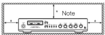
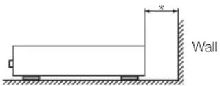
Install this unit in a location where good ventilation and heat radiation are assured.
Especially, the installation of this unit where the direct sunlight is present, where the temperature rises excessively high such as close to a heater, or where it is humid or dusty may cause a malfunction even if heat is efficiently released. Therefore, do not install this unit in such places.
Note:
For heat dispersal, do not install this equipment in a confined space such as a book case or similar unit.
Cautions in connecting cartridges
Connect an analog player or a tone arm with the ground terminal of this unit.
If the grounding terminal is inadequately connected, noises including hum may be generated, resulting in an adverse S/N ratio.
The pin plugs to be inserted in the input terminals of this unit shall be pushed in firmly. If the grounding of the terminal is inadequately connected, noises including hum may be generated, resulting in an adverse effect on the S/N ratio.
Precautions in connecting with other components
When connecting this unit to input/output devices, be sure to turn off the power switch of this unit and all other connected units.
The pin-plugs to be inserted in the input and output terminals of this unit shall be pushed in firmly. If the grounding terminal is inadequately connected, noises including hum may be generated, resulting in an adverse effect on the S/N ratio.
The sound is not generated shortly after the power supply is turned on
This amplifier is equipped with a time muting circuit in order to separate the output circuit. Therefore, no sound is generated shortly after the power supply is turned on.
If the volume control is set to a high sound level before the time muting circuit is canceled, a large sound will suddenly be generated. Please be advised that the volume control shall be set to a low level at first and adjusted after the sound comes out of the speakers.
Repair and adjustment
When repairs and adjustments are needed, please consult with the dealer you bought the unit from.
Cleaning
For cleaning, use a piece of soft cloth to wipe the unit such as cleaning cloth. When the dirt is hard to remove, use a small amount of neutral detergent to wipe, and then wipe the unit with dry cloth. Do not use a solvent like benzine or thinner because such a substance can often damage the exterior.
Features of This Unit
Outline
This unit is a non-feedback CR type phono equalizer amplifier that is configured with the vacuum-tube-equipped SRPP (Shunt Regulated Push-Pull) circuit.
Non-feedback CR type equalizer circuit
Various high sound quality parts that have been carefully selected are used in this non-feedback CR type equalizer circuit.
Input stage SRPP circuit
The SRPP (Shunt Regulated Push-Pull) circuit that features a low impedance output, prolonged life of vacuum tubes, and many other advantages, is used in the phono equalizer section.
Specially selected MC transformer
Four pieces of step-up transformers in which a super permalloy core is independently used are mounted. Independence among MC-HIGH, MC-LOW, left and right respectively has achieved richly expressive sound that can be produced only by boosting with a transformer.
Articulation function
Magnetization of the cartridge or MC transformer that may cause the deterioration of sound quality can be eliminated with the use of reproduced sound signals. This function can exploit the full potential of cartridges and achieve the sound quality with a sense of openness.
Vriable cartridge load impedance
The load resistance variable function from 30 kΩ through 100 kΩ supports a wide variety of cartridges.
Setting of cartridge load capacity
The load capacity setting function with 6 positions supports a wide variety of cartridges. Change in high-pass characteristics allows sound to be adjusted to your favorite tone quality.
Switchover of gains
The gain selection switch with 3 positions (36 dB/38 dB/40 dB) is equipped.
Output transformer
The output transformer with a super permalloy core is equipped to achieve richly and deeply expressive sound. The balanced output is also supported.
Analog meter
Analog meters with a sensitivity selection switch are introduced to make various cartridge outputs available. The meter-off function is also equipped. (When OFF is selected, the meter needles do not move.)
Thin body design
This unit can be installed in a limited space.
Low cut switch
A low-cut filter is provided to restrain woofer fluctuation generated due to warped analog records.
High cut switch
A high-cut filter is provided to eliminate scratch noises and it makes music easier to be listened to.
Stereo/Monaural
The monaural switch which is useful for playing monaural records is provided.
High-inertia power supply
The high-inertia power supply circuit that is a combination of a large-capacity Ol-core-type power transformer and a large-capacity capacitor block is introduced.
Power supply unit
Full wave rectification by a rectifier tube EZ81 (duo diode) and a choke coil are used.
LUXMAN's original OFC wires
Our original OFC wires are used in the internal wiring to achieve smooth signal transmissions thanks to the spiral wrap shielding on each core and the non-plating process on the core wire.
AC inlet
This inlet enables the connection with an external power cable.
Selector relays
The selector relays of the high sound quality which are mounted in the important points of LUXMAN amplifiers also are mounted.
Input/output terminals
18 mm pitch RCA input terminals and Neutrik made XLR terminals allow even a high-performance line cable with large plug to be connected.
Names and Functions
Front panel
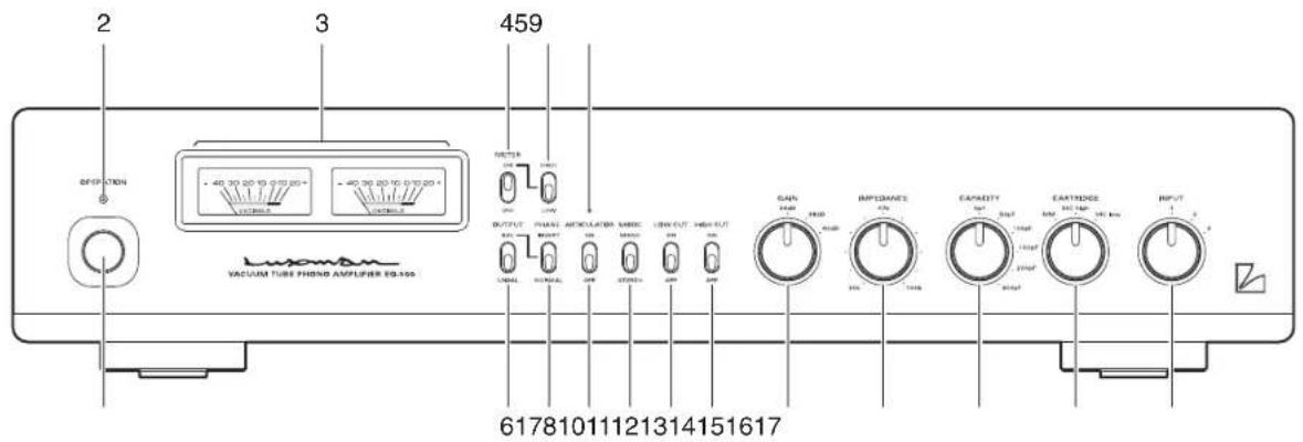
1. Operation switch (OPERATION)
This switch turns on and off the power. When connecting the input/output terminals, be sure to turn off this switch.
□ : Off
□: On
2. Operation indicator (OPERATION)
Blinks during warm-up when the operation switch is turned on and lights up when the operation state is activated afterward.
When the indicator is blinking, the output muting circuit is activated to mute sound. Please be advised that the volume control of the input device such as a control amplifier shall be set to a low level at first and adjusted according to your taste after sound comes out of the speakers.
3. Meters
Indicate the levels of outputs with illumination.
4. Meter switch (METER)
Turns on and off the meter illumination and meter display.
• ON
Turns on the meter illumination and meter display.
•OFF
Tums off the meter illumination and meter display.
5. Meter sensitivity selection switch
Selects the sensitivity of the meter display. Set this switch to the low position under normal conditions. When the meter needle swings in a narrow range, set the switch to the high position. When the meter switch is set to OFF, the sensitivity cannot be changed.
- LOW
Use this position under normal conditions.
• HIGH
When the meter needle swings in a narrow range, set the switch to this position.
6. Output mode selection switch (OUTPUT)
Switches the output between unbalanced output and balanced output.
- UNBAL
Sound comes out from LINE-1 and LINE-2.
• BAL
Sound comes out from BAL-LINE.
7. Balanced phase inversion switch (PHASE)
Inverts the phase when the output mode selection switch (OUTPUT) is set to the balanced output. The phase shall be corresponding to the phase of the device to be connected.
• NORMAL ① GROUND
② COLD (-)
③ HOT (+)
- INVERT ① GROUND
② HOT (+)
③ COLD (-)
8. Articulator switch (ARTICULATOR)
This function performs demagnetization by using sound signals.
When a record is played with the articulator set to ON, the cartridge and step-up transformer are demagnetized, and thus the expression of fresh sound is brought back.
When the articulator is set to ON, no sound is generated or the sound becomes remarkably small during playback. This is the sign that the cartridge is being demagnetized. If the articulator is set to OFF at this point, the sound suddenly becomes loud. Therefore, do not turn up the sound volume of the control amplifier or the like. It is recommended to activate the articulator for approximately 30 seconds before the end of a track of the record.
• OFF
Deactivates the articulator. Select this position under normal conditions.
• ON
Activates the articulator.
9. Articulator indicator
Turns on when the articulator is activated.
10. Mode switch (MODE)
• STEREO
Is used for stereo playback. Select this position under normal conditions.
• MONO
Is used for monaural playback.
11. Low cut switch (LOW CUT)
Toggles the low-frequency cutoff function on and off. The speaker (woofer) fluctuation is restrained. When a warped record is played.
• OFF
Provides the normal state.
• ON
Cuts low frequencies of 20 Hz or less. (-6 dB/oct)
12. High cut switch (HIGH CUT)
Toggles the high-frequency cutoff function on and off.
• OFF
Provides the normal state.
• ON
Cuts high frequencies of 8 kHz or more. (-6 dB/oct)
13. Gain selection switch (GAIN)
Selects the gain among 36 dB, 38 dB, and 40 dB. The gain is selectable according to the output voltage of the cartridge.
14. Input impedance control (IMPEDANCE)
Controls the input impedance according to your cartridge. The variable range is from 30 kΩ through 100 kΩ.
15. Input capacitor selection switch (CAPACITIY)
Selects the input capacitor according to your cartridge. Selectable capacitors are the following: 0 pF/50 pF/100 pF/150 pF/200 pF/300 pF
16. Cartridge selection switch (CARTRIDGE)
Selects the input impedance. The selectable positions are MM, MC low and MC high. Select a position in accordance with the input impedance specified in the operating instructions of the cartridge.
| Cartridge selection | MM MC high MC low | ||
| Impedance 30 | kΩ - 100 kΩ 40Ω | 2.5Ω | |
17. Input selection switch (INPUT)
Selects an input terminal on the rear panel.
• 1: Input terminal 1 (INPUT-1) is selected.
• 2: Input terminal 2 (INPUT-2) is selected.
• 3: Input terminal 3 (INPUT-3) is selected.
Names and Functions
Rear panel
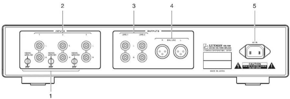
1. Signal ground terminals (SIGNAL GROUND)
Are ground terminals for devices to be connected to this unit. These terminals are used to reduce noises when other devices are connected, and are connected to an analog player or a tone arm. These terminals are not designed for safety. There are 3 lines of independent ground terminals to allow for connecting 3 pieces of analog players or tone arms.
2. Input terminals (INPUTS)
Are used as an input terminal to connect a pin-plug cable from an analog player or a tone arm. There are 3 lines of input terminals to connect 3 pieces of analog players or tone arms. The input selection switch can select an input among 1, 2, and 3.
3. Unbalanced output terminals/(OUTPUTS) (LINE-1, LINE-2)
RCA terminals to provide unbalanced audio signals of this unit. Connect these terminals to unbalanced inputs of an input device such as a control amplifier with pin-plug cables. Audio output signals are selected with the output mode selection switch.
LINE-1 and LINE-2 provide the same sound quality.
When the output mode selection switch is set to BAL, no audio signal is outputted.
4. Balanced output terminals (OUTPUTS) (BAL. LINE)
XLR output terminals to provide balanced audio signals from this unit Connect these terminals to balanced inputs of an input device such as a control amplifier with balanced cables. Audio output signals are selected with the output mode selection switch.
When the output mode selection switch is set to UNBAL, no audio signal is outputted.
5. AC inlet (AC IN)
Connects the accessory power cable.
The power shall be supplied from a household wall socket.
LUSOMAN
VACUUM TUBE PHONO AMPLIFIER EQ-500
Connections
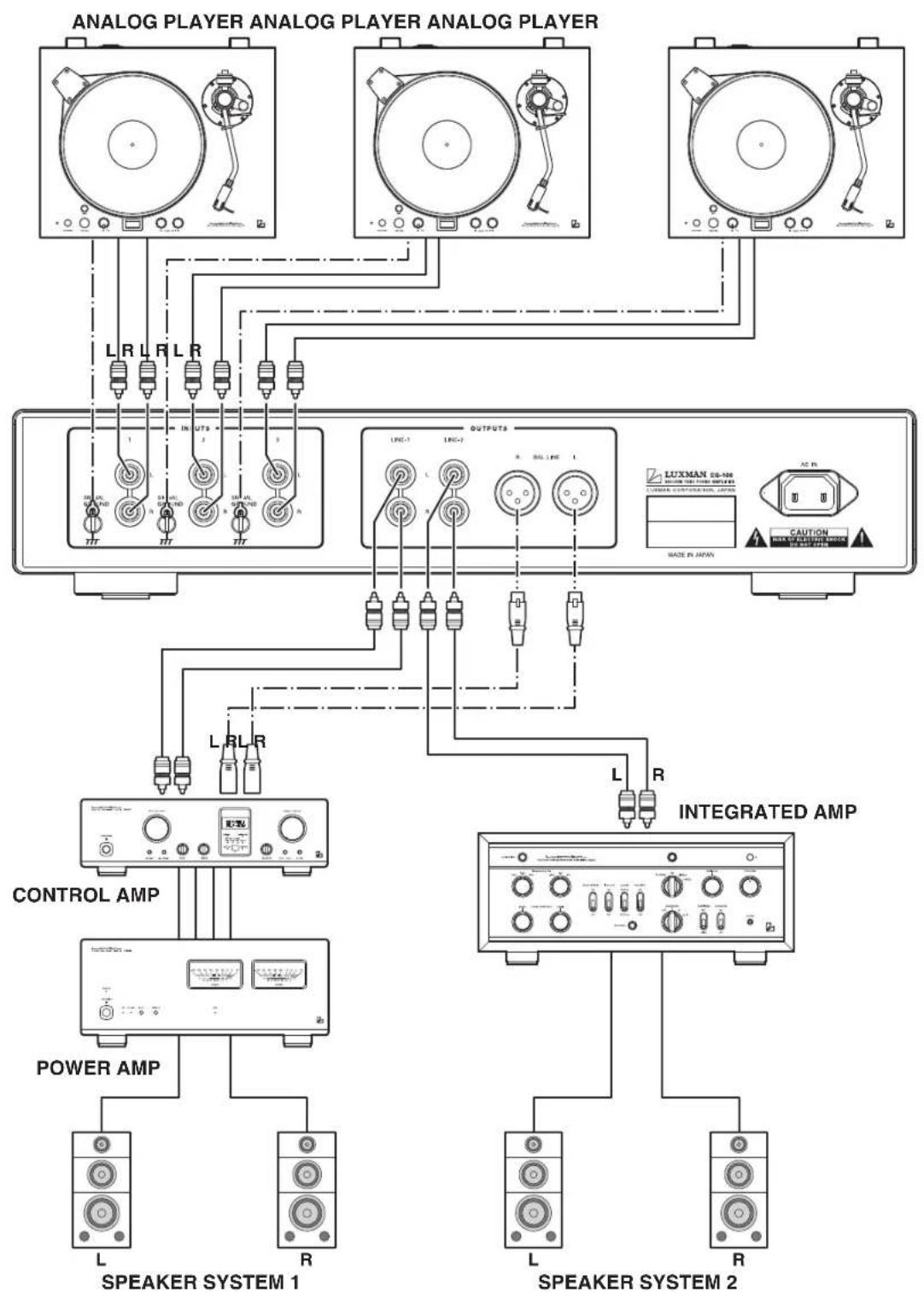
flowchart
graph TD
    A["ANALOG PLAYER ANALOG PLAYER ANALOG PLAYER"] --> B["L R L R L R"]
    A --> C["OUTPUTS"]
    A --> D["CONTROL AMP"]
    A --> E["POWER AMP"]
    B --> F["L R L R"]
    C --> G["L R"]
    D --> H["L R"]
    E --> I["L R"]
    F --> J["CAPUTION"]
    G --> K["INTEGRATED AMP"]
    H --> L["SPEAKER SYSTEM 1"]
    I --> M["SPEAKER SYSTEM 2"]
    J --> N["L"]
    K --> O["L"]
    L --> P["R"]
Before Connecting
Before connecting other devices, connect the jack side of the accessory power cable to the AC inlet of this unit.
Before connection is made, turn off the main power switch of this unit and the power of all other connected devices to prevent accidents due to noises generated unexpectedly.
How to connect power supply
Use the accessory power cable and insert the AC plug in an outlet on the wall in the room where the unit will be installed.
How to connect output devices
- Surely connect the output terminals of this unit to the line input terminals of a control amplifier or an integrated amplifier using RCA pin-plug cables between the R-channel and L-channel. If the grounding side of the pin-plug cables is inadequately connected, noises including hum may be generated, resulting in an adverse effect on the S/N ratio. Therefore, insert the cables all the way.
- Do not connect the output terminals of this unit to the phono (PHONO) input terminal of a control amplifier or integrated amplifier. Failure to observe this may not only distort the phono amplifier signals of the integrated amplifier or a control amplifier but also damage the amplifiers. Be sure to connect the terminal to the line input terminal. Do not insert the supplied short pin into the output terminal. If the pin is inserted into the output terminal, no sound will be generated.
- Sound volume adjustment shall be performed by the connected control amplifier or integrated amplifier because this unit has no sound volume adjustment function. Sound volume shall be set to the minimum when this unit is being connected. If sound volume is set to a high level at power-on, sudden loud sound may be generated, which may cause hearing loss or damage to the speakers.
Please be advised that the sound volume shall be set to a low level at first and adjusted according to your taste after the sound comes out of the speakers.
Cartridge connection
- Insert the pin-plugs of an RCA pin-plug cables from an analog player or a tone arm with a cartridge mounted into the input terminals of this unit. At this moment, be sure to make a connection without a mistake between the R-channel and L-channel. If the grounding side of the pin-plug cables is inadequately connected, noises including hum may be generated, resulting in an adverse effect on the S/N ratio.
- Grounding between analog players or tone arms and this unit is needed. Be sure to connect the ground wires that come from tone arms in parallel with pin-plug cables to the ground terminals of this unit.
If the ground wires are inadequately connected, noises including hum may be generated, resulting in an adverse effect on the S/N ratio. - To listen to music with the analog player connected to the input terminal 1, 2, or 3 and cartridge, select the connected input terminal with the input selection switch.
Do not connect the output of an analog player with phono equalizer embedded to this unit. Failure to observe this may not only distort the amplifier signals but also cause a malfunction.
Connect the output of an analog player with phono equalizer embedded to the line input of an integrated amplifier or a control amplifier.
Block Diagram
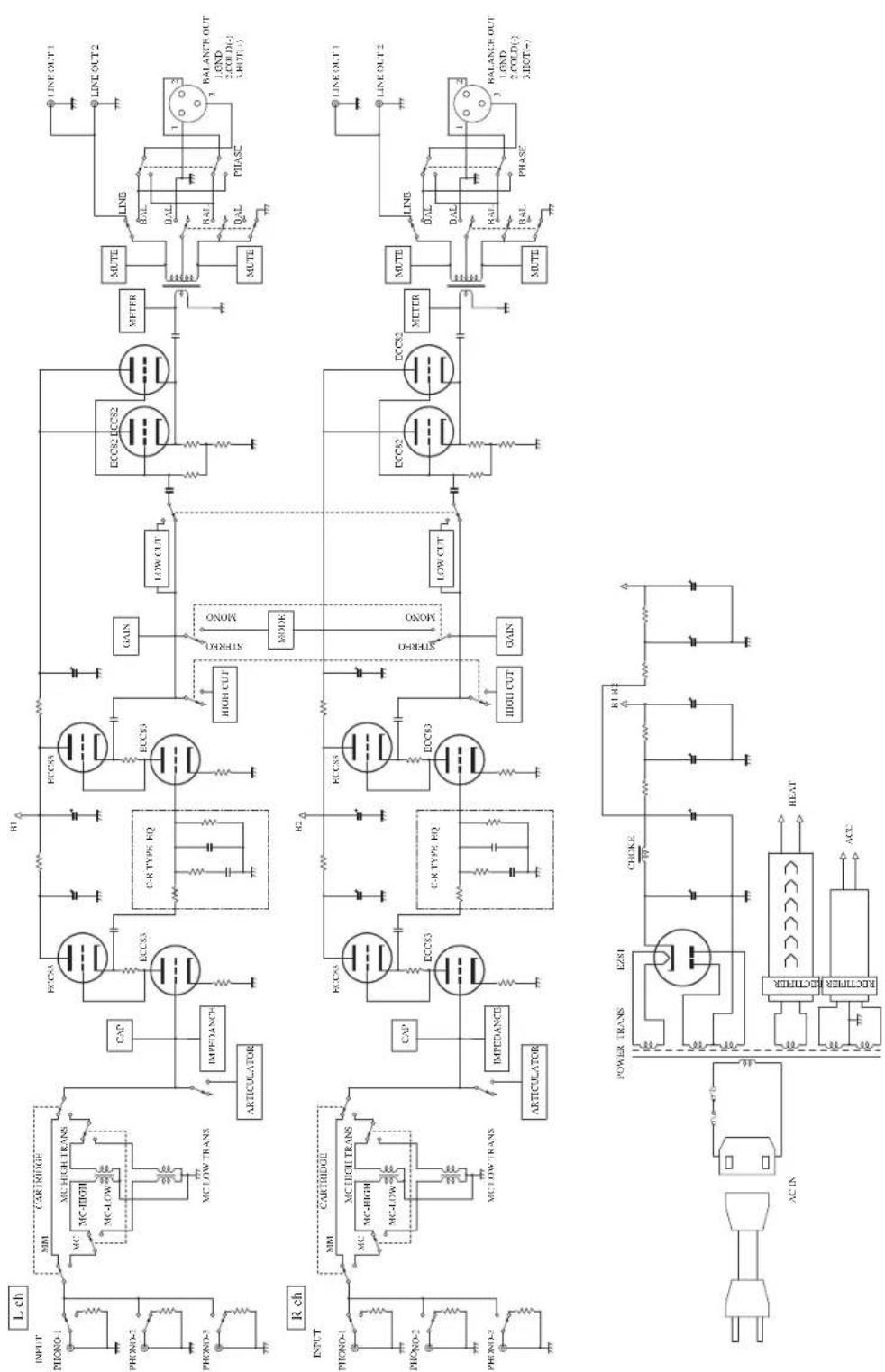
flowchart
graph TD
    subgraph_Input_1["INPUT"]
        direction TB
        A["PHONO-1"] --> B["MM"]
        B --> C["MC HIGH TRANS"]
        C --> D["MC LOW TRANS"]
        D --> E["MC LOW TRANS"]
        E --> F["CAP"]
        F --> G["ECCS3"]
        G --> H["C-R TYPE EQ"]
        H --> I["HIGH CUT"]
        I --> J["LOW CUT"]
        J --> K["ECCS2 ECCS2"]
        K --> L["METER"]
        L --> M["LING"]
        M --> N["BALANCE OUT 1. OND 2.COLD(-) 3.IOT(-)"]
        M --> O["RALANCE OUT 1. OND 2.COLD(-) 3.IOT(-)"]
        P["PHONO-2"] --> Q["MM"]
        Q --> R["MC HIGH TRANS"]
        R --> S["MC LOW TRANS"]
        S --> T["CAP"]
        T --> U["ECCS5"]
        U --> V["C-R TYPE EQ"]
        V --> W["HIGH CUT"]
        W --> X["LOW CUT"]
        X --> Y["ECCS8"]
        Y --> Z["METER"]
        Z --> AA["LING"]
        AA --> AB["RALANCE OUT 1. OND 2.COLD(-) 3.IOT(-)"]
        Z --> AC["RALANCE OUT 1. OND 2.COLD(-) 3.IOT(-)"]
    end

    subgraph_Input_2["INPUT"]
        direction TB
        AD["PHONO-1"] --> AE["MM"]
        AE --> AF["MC HIGH TRANS"]
        AF --> AG["MC LOW TRANS"]
        AG --> AH["CAP"]
        AH --> AI["ECCS3"]
        AI --> AJ["C-R TYPE EQ"]
        AJ --> AK["HIGH CUT"]
        AK --> AL["LOW CUT"]
        AL --> AM["ECCS2 ECCS2"]
        AM --> AN["METER"]
        AN --> AO["LING"]
        AO --> AP["RALANCE OUT 1. OND 2.COLD(-) 3.IOT(-)"]
        AO --> AQ["RALANCE OUT 1. OND 2.COLD(-) 3.IOT(-)"]
    end

    subgraph_Input_3["INPUT"]
        direction TB
        AR["PHONO-2"] --> AS["MM"]
        AS --> AT["MC HIGH TRANS"]
        AT --> AU["MC LOW TRANS"]
        AU --> AV["CAP"]
        AV --> AW["ECCS5"]
        AW --> AX["C-R TYPE EQ"]
        AX --> AY["HIGH CUT"]
        AY --> AZ["LOW CUT"]
        AZ --> BA["ECCS8"]
        BA --> BB["METER"]
        BB --> BC["LING"]
        BC --> BD["RALANCE OUT 1. OND 2.COLD(-) 3.IOT(-)"]
    end

    subgraph_Power_Trans["POWER TRANS"]
        direction LR
        BEZSI["EZSI"] --> BF["CHOKE"] --> BG["B1 B2"]
    end

    subgraph_AC_IN["AC IN"]
        direction LR
        RECTHER["RECTHER"] --> BF
    end

    subgraph_HEAT["HEAT"]
        direction LR
        ACC["ACC"] --> BF
    end
Specifications
LUSOMSM
VACUUM TUBE PHONO AMPLIFIER EQ-500
| Input sensitivityWhen the gain is set to 36 dB | MM : 4mV/250mV, LINE output 1kHz, Load 50kΩMC-HIGH : 0.44mV/250mV, LINE output 1kHz, Load 50kΩMC-LOW : 0.18mV/250mV, LINE output 1kHz, Load 50kΩMM : 4mV/250mV, BAL output 1kHz, Load 100kΩMC-HIGH : 0.44mV/250mV, BAL output 1kHz, Load 100kΩMC-LOW : 0.18mV/250mV, BAL output 1kHz, Load 100kΩ |
| Input impedance MM : 30 kΩ - 100 kΩ (variable) | |
| MC-HIGH : 40ΩMC-LOW : 2.5Ω | |
| GainWhen the gain is set to 36 dB | MM : 36dB (1kHz)MC-HIGH : 55dB (1kHz)MC-LOW : 63dB (1kHz) |
| RIAA deviation MM : 20 - 20kHz ±0.3dB | |
| MC-HIGH : 20 - 20kHz ±0.3dBMC-LOW : 20 - 20kHz ±0.3dB | |
| Maximum allowable input voltage1kHz | MM : 300mVMC-HIGH : 34mVMC-LOW : 13mV |
| Output impedance LINE OUT : 850Ω | |
| BAL OUT : 850Ω | |
| S/N ratioWhen the gain is set to 36 dB | MM : 76dB (IHF-A)MC-HIGH : 75dB (IHF-A)MC-LOW : 74dB (IHF-A) |
| Total harmonic distortion1 kHz, 1 V outputWhen the gain is set to 36 dB | 0.07% |
| Channel separation (10kHz) 65dB | |
| Accessories • Power cable | • Safety cautions• Owner's manual |
| Circuit SRPP, Final stage cathode follower, Non-feedback CR type | |
| Vacuum tube used ECC83 x 4 pieces, ECC82 x 2 pieces, and EZ81 x 1 piece | |
| Power consumption 47 W | |
| Power supply 230 V ~ (50 Hz) | |
| Max. external dimensions 440 (W) x 92 (H) x 397 (D) mm(front side knob of 5mm and rear side terminal of 12mm included in depth) | |
| Weight | 12.5 kg (main unit only) |
* Specifications and the appearance are subject to change without notice.
Before Asking for Repair Services
While the unit is used, an unusual phenomenon may be confused as a malfunction for a certain reason. Prior to asking our official sole distributor of your country for repair services, please check the table below and read the operating instructions for the subsidiary devices. If the cause of the malfunction cannot be identified, please contact your dealer. When we have once accepted your request for repair services, inspection fees and traveling expenses may be claimed even though the unit is found to be normal.
Problem Cause Solution
| No power is supplied even though the power switch is pressed ON. | The power plug is disconnected from the wall outlet, or it is not completely inserted.The power plug is disconnected from the AC inlet, or it is not inserted completely. | Insert the power plug in the wall outlet completely.Securely insert the power plug in the AC inlet completely. |
| No sound is generated.(small sound) | Connection is not securely performed.Make cable connections securely.The connected input terminal does not match the number selected with the input selection switch.The selected item of the input selection switch of the control amplifier is not appropriate.The volume control of the input device such as a control amplifier is set to the minimum.The used cartridge type does not match with the selected item of the cartridge selection switch.The articulator switch is set to ON. | Match the input terminal with the number of the input selection switch.Select the correct input with the input selection switch of the control amplifier.Adjust the volume control of the input device such as a control amplifier.Select the correct item of the cartridge selection switch according to the used cartridge.Turn down the sound volume, set the articulator switch to OFF, and adjust the sound volume according to the appropriate input impedance after sound comes out. |
| The connected output terminal does not match the selected item of the output mode selection switch.The short pin is inserted into an unbalanced output terminal.The setting of the input impedance control does not match the cartridge in use. | Match the output terminal with the item of the output mode selection switch.Pull out the short pin from the unbalanced output terminal.Adjust the input impedance according to the cartridge in use. | |
| Hum noises (boon or zzz noise) are generated. | The grounding side of the connection cable has no contact with the terminal.The grounding of the shell or tone arm is inadequately connected.Induction noise is picked up from a power transformer of another device.The connecting cables are too close to the power cable. | Make cable connections securely.Be sure to connect the ground wire of the shell or tone arm to the ground terminal.Install it distant from other devices.Keep the connecting cables away from the power cable. |
MEMO
LUSOMAN
VACUUM TUBE PHONO AMPLIFIER EQ-500


LUXMAN CORPORATION, JAPAN
AG00987E41A
Printed in China
- Precautions
- Installation place
- Note:
- Cautions in connecting cartridges
- Precautions in connecting with other components
- The sound is not generated shortly after the power supply is turned on
- Repair and adjustment
- Cleaning
- Features of This Unit
- Outline
- Non-feedback CR type equalizer circuit
- Input stage SRPP circuit
- Specially selected MC transformer
- Articulation function
- Vriable cartridge load impedance
- Setting of cartridge load capacity
- Switchover of gains
- Output transformer
- Analog meter
- Thin body design
- Low cut switch
- High cut switch
- Stereo/Monaural
- High-inertia power supply
- Power supply unit
- LUXMAN's original OFC wires
- AC inlet
- Selector relays
- Input/output terminals
- Names and Functions
- Operation switch (OPERATION)
- Operation indicator (OPERATION)
- Meters
- Meter switch (METER)
- Meter sensitivity selection switch
- Output mode selection switch (OUTPUT)
- Balanced phase inversion switch (PHASE)
- Articulator switch (ARTICULATOR)
- Articulator indicator
- Mode switch (MODE)
- Low cut switch (LOW CUT)
- High cut switch (HIGH CUT)
- Gain selection switch (GAIN)
- Input impedance control (IMPEDANCE)
- Input capacitor selection switch (CAPACITIY)
- Cartridge selection switch (CARTRIDGE)
- Input selection switch (INPUT)
- Signal ground terminals (SIGNAL GROUND)
- Input terminals (INPUTS)
- Unbalanced output terminals/(OUTPUTS) (LINE-1, LINE-2)
- Balanced output terminals (OUTPUTS) (BAL. LINE)
- AC inlet (AC IN)
- Connections
- Before Connecting
- How to connect power supply
- How to connect output devices
- Cartridge connection
- Block Diagram
- Specifications
- LUSOMSM
- VACUUM TUBE PHONO AMPLIFIER EQ-500
- Before Asking for Repair Services
Brand : LUXMAN
Model : EQ-500
Category : Receiver