
SPF 6000-18000T -MPV - Uncategorized Growatt - Free user manual and instructions
Find the device manual for free SPF 6000-18000T -MPV Growatt in PDF.


| Product Type | Off-Grid Solar Inverter/Charger with MPPT |
| Model | SPF 6000T DVM-MPV (part of SPF 6000-18000T series) |
| Rated Power | 6000 W (6 kW) |
| Surge Rating (20 ms) | 18,000 W (18 kW) |
| Battery Voltage | 48 VDC |
| AC Output Voltage | 104-120 Vac / 208-240 Vac (selectable) |
| Output Frequency | 50/60 Hz (auto sensing) |
| Waveform | Pure sine wave (same as input in bypass) |
| Max PV Array Open Circuit Voltage | 250 VDC (MPV models) |
| Max PV Charge Current | 80 A (4-6 kW models), 120 A (8-12 kW models) |
| MPPT Voltage Range | 60-245 VDC |
| Maximum Efficiency (Solar) | 97.5% |
| AC Input Voltage Range | 154-272 Vac (appliance mode) / 184-272 Vac (UPS mode) |
| Maximum AC Charge Current | 60 A (6 kW model) |
| Transfer Time | 10 ms typical |
| Dimensions (W x H x D) | 540 x 360 x 218 mm (4-6 kW models) |
| Net Weight | 45 kg (6 kW model) |
| Operating Temperature | 0°C to 50°C |
| Storage Temperature | -20°C to 60°C |
| Protections | Overload, short circuit, over temperature, low battery, high battery, fan fault |
| Charging Stages | Bulk, Absorption, Float, Equalization (selectable) |
| Communication Ports | WiFi/GPRS, RS485, BMS (CAN/RS485), Dry contact, USB |
| Display | LCD with icons and settings |
| Cooling | Intelligent fan control (DC and AC fans) |
| Spare Parts / Repair | Fans, communication cables, BMS port; service by qualified personnel |
| Standards | Suitable for mounting on concrete or non-combustible surfaces |
Frequently Asked Questions - SPF 6000-18000T -MPV Growatt
User questions about SPF 6000-18000T -MPV Growatt
0 question about this device. Answer the ones you know or ask your own.
Ask a new question about this device
Download the instructions for your Uncategorized in PDF format for free! Find your manual SPF 6000-18000T -MPV - Growatt and take your electronic device back in hand. On this page are published all the documents necessary for the use of your device. SPF 6000-18000T -MPV by Growatt.
USER MANUAL SPF 6000-18000T -MPV Growatt
Information on this Manual ....1
Validity ....1
Scope....1
Target Group....1
Safety Instructions ....1
Introduction......2
Features 2
Product Overview 3
Installation....4
Unpacking and Inspection......4
Preparation....4
Mounting the Unit....4
Battery Connection....5
AC Input/Output Connection 8
PV Connection....10
Communication Connection ....11
Dry Contact Signal....11
Electrical Performance 12
Operation 15
Power ON/OFF 15
Operation and Display Panel....15
LCD Display Icons....16
LCD Setting....18
Display Information....23
Operating Mode Description 26
Fault Reference Code....27
Warning Indicator....27
Trouble Shooting....28
Specifications 29
Information on this Manual
Validity
This manual is valid for the following devices:
SPF 4000T DVM
SPF 4000T DVM-MPV
SPF 5000T DVM
SPF 5000T DVM-MPV
SPF 6000T DVM
SPF 6000T DVM-MPV
SPF 8000T DVM
SPF 8000T DVM-MPV
SPF 10000T DVM
SPF 10000T DVM-MPV
SPF 12000T DVM
SPF 12000T DVM-MPV
Scope
This manual describes the assembly, installation, operation and troubleshooting of this unit. Please read this manual carefully before installations and operations.
Target Group
This document is intended for qualified persons and end users. Tasks that do not require any particular qualification can also be performed by end users. Qualified persons must have the following skills:
Knowledge of how an inverter works and is operated
Training in how to deal with the dangers and risks associated with installing and using electrical devices and installations
▶ Training in the installation and commissioning of electrical devices and installations
Knowledge of the applicable standards and directives
Knowledge of and compliance with this document and all safety information
Safety Instructions

WARNING: This chapter contains important safety and operating instructions. Read and keep this manual for future reference.
- CAUTION – Only qualified personnel can install this device with battery.
- Before using the unit, read all instructions and caution marks on the unit, understand the batteries and all appropriate sections of this manual.
- CAUTION --To reduce risk of injury, charge only deep-cycle lead acid type rechargeable batteries. Other types of batteries may burst, causing personal injury and damage.
- NEVER cause AC output and DC input short circuit. Don't connect to the mains when DC input short circuits.
- NEVER charge a frozen battery.
- Do not disassemble the unit. Take it to a qualified service center when service or repair is required. Incorrect re-assembly may result in a risk of electric shock or fire.
- To reduce risk of electric shock, disconnect all wiring before attempting any maintenance or cleaning. Turning off the unit will not reduce this risk.
- Be very cautious when working with metal tools on or around batteries. A potential risk, such as dropping a tool to spark or short circuit batteries or other electrical parts, could cause an explosion.
- For optimum operation of this off grid solar inverter, please follow required spec to select appropriate cable size. It's very important to correctly operate this off grid solar inverter.
- Please strictly follow installation procedure when you want to disconnect AC or DC terminals. Please refer to INSTALLATION section of this manual for the details.
- GROUNDING INSTRUCTIONS – This off grid solar inverter should be connected to a permanent grounded wiring system. Be sure to comply with local requirements and regulation to install this inverter.
- Warning!! Only qualified service persons are able to service this device. If errors still persist after following troubleshooting table, please contact local dealer or service center for maintenance.
Introduction
flowchart
graph TD
    A["Solar Panel"] --> B["Generator"]
    C["Utility Grid"] --> B
    D["Battery"] --> B
    E["WiFi-F / GPRS-F"] --> F["ShineServer"]
    F --> G["Internet"]
    G --> H["ShinePhone"]
    I["120V"] --> J["L1"]
    K["240V"] --> L["N"]
    M["120V"] --> N["L2"]
    O["Home Loads"] --> P["ShineServer"]
Hybrid Power System
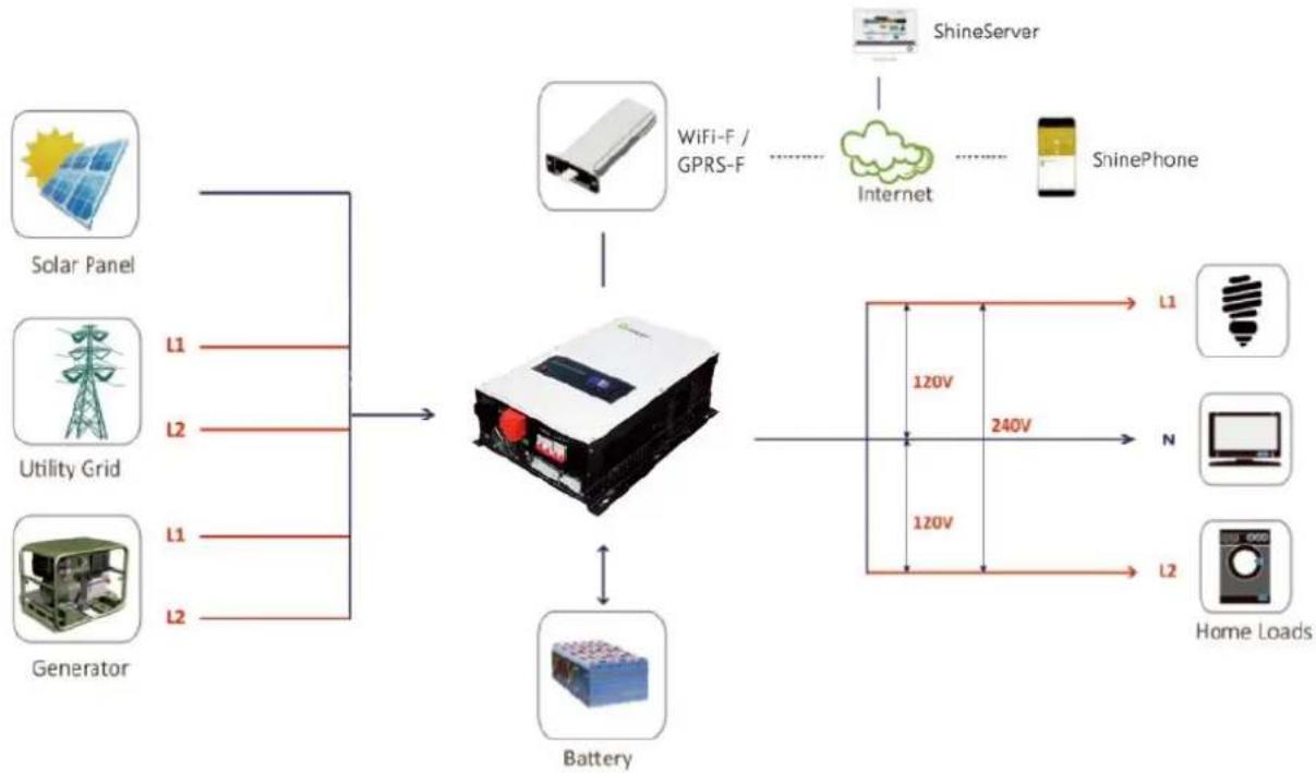
This is a multifunctional split-phase output off grid solar inverter, integrated with a MPPT solar charge controller, a low frequency pure sine wave inverter and a UPS function module in one machine, which is perfect for off grid backup power and self-consumption applications.
The whole system also need other devices to achieve complete running such as PV modules, generator, or utility grid. Please consult with your system integrator for other possible system architectures depending on your requirements. The WiFi / GPRS module is a plug-and-play monitoring device to be installed on the inverter. With this device, users can monitor the status of the PV system from the mobile phone or from the website anytime anywhere.
Features
▶ Rated power 4KW to 12KW
MPPT solar charge controller
Low frequency inverter with large transformer
Pure sine wave AC output
▶ Overload, short circuit and deep discharge protection
▶ Configurable AC/ solar input priority via LCD setting
▶ Compatible to mains voltage or generator power
WiFi/ GPRS remote monitoring
Product Overview
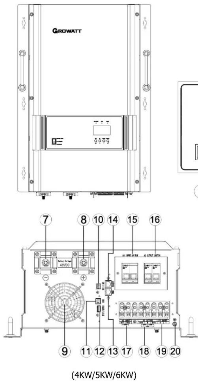
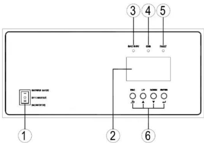
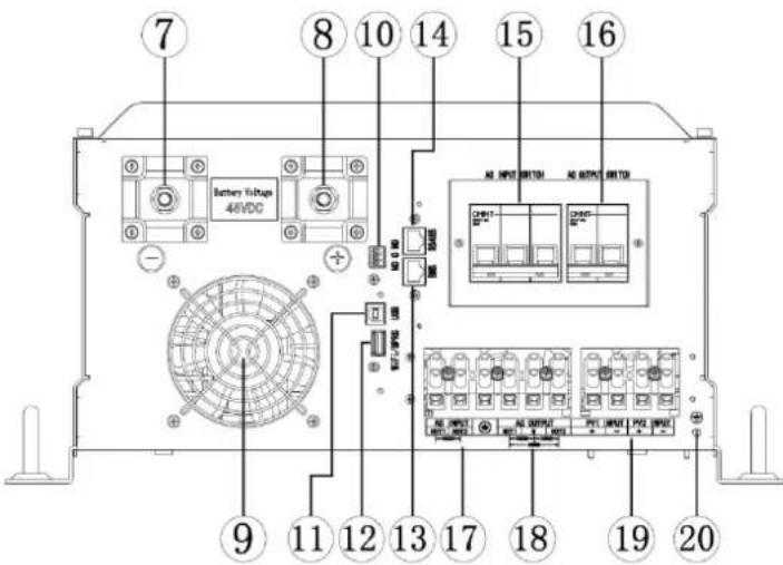
(8KW/10KW/12KW)
- ON/OFF Power Switch
- Status Indicator
- Fault Indicator
- Negative Battery Terminal
- DC Fan
- USB Port
- BMS Port
- AC Input Breaker
- AC Input Terminal
-
PV Input Terminal
-
LCD Display
- Charging Indicator
- Function Buttons
- Positive Battery Terminal
- Dry Contact For AGS
- Wi-Fi/GPRS Device Port
- RS485/Remote LCD Port (Optional)
- AC Output Breaker
- AC Output Terminal
- Grounding Terminal
Installation
Unpacking and Inspection
Before installation, please inspect the unit. Be sure that nothing inside the package is damaged. You should have received the following items in the package:
The unit x1
▶ User manual x 1
▶ Communication cable x 1
Preparation
Before connecting all wiring, please take off bottom cover by removing eight screws as shown below.
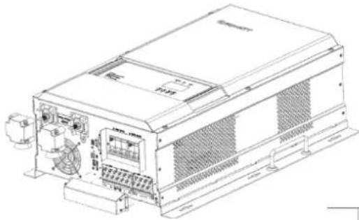
natural_image
Technical line drawing of a mechanical device with control panel and fan (no text or symbols)Mounting the Unit
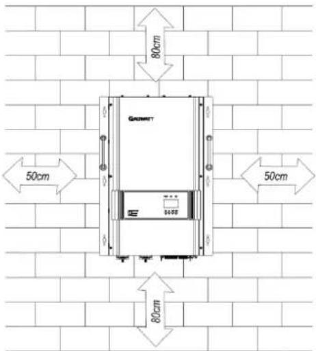
Consider the following points before selecting where to install:
Do not mount the inverter on flammable construction materials.
Mount on a solid surface
Install this inverter at eye level in order to allow the LCD display to be read at all times.
The ambient temperature should be between 0^ C and 50^ C to ensure optimal operation.
The recommended installation position is to be adhered to the wall vertically.
Be sure to keep other objects and surfaces as shown in the right diagram to guarantee sufficient heat dissipation and to have enough space for removing wires.

SUITABLE FOR MOUNTING ONCONCRETE OR OTHER NON-COMBUSTIBLE SURFACE ONL
![GROWATT M6 220 [8.661°] 540 [21.260°] 180 [7.087°] 360 [14.173°] 400 [15.748°] 440 [17.323°] 4~6KW](/content/2026/05/855022/images/242739341eb0f0c325043eb88e2f7106f70cc307e234d9af7406bfa35bb3e258.jpg)
Install the unit by screwing the six setscrews.
![GROWATT 380 [14.961"] 420 [16.535"] 460 [18.110"] 8~12KW 240 [9.449"] 280 [11.024"] 650 [25.591"] N6](/content/2026/05/855022/images/a67295492e9b40b25c2f7aeaaff4c8d2127c590431794d7d0101dde51603cebf.jpg)
Battery Connection
CAUTION: For safety operation and regulation compliance, it's requested to install a separate DC over-current protector or disconnect device between battery and inverter. It may not be requested to have a disconnect device in some applications, however, it's still requested to have over-current protection installed. Please refer to typical amperage in below table as required fuse or breaker size.
WARNING! All wiring must be performed by a qualified person.
WARNING! It's very important for system safety and efficient operation to use appropriate cable for battery connection. To reduce risk of injury, please use the proper recommended cable and terminal size as below.
Recommended battery cable and terminal size:
| Model | Battery Voltage | Wire Gage/min0~1.0m | Wire Gage/min1.0~5.0m |
| 4kw | 48V | 30 mm ^2 | 40 mm ^2 |
| 5kw | 48V | 40 mm ^2 | 50 mm ^2 |
| 6kw | 48V | 50 mm ^2 | 60 mm ^2 |
| 8kw | 48V | 60 mm ^2 | 75 mm ^2 |
| 10kw | 48V | 75 mm ^2 | 90 mm ^2 |
| 12kw | 48V | 90 mm ^2 | 120 mm ^2 |
Please follow below steps to implement battery connection:
- Assemble battery ring terminal based on recommended battery cable and terminal size.
- Connect all battery packs as units requires. It's suggested to connect at least 200Ah capacity battery for 4KW\~6KW model and at least 400Ah capacity battery for 8KW\~12KW model.
- Insert the ring terminal of battery cable flatly into battery connector of inverter and make sure the bolts are tightened with torque of 2-3 Nm. Make sure polarity at both the battery and the inverter/charge is correctly connected and ring terminals are tightly screwed to the battery terminals.
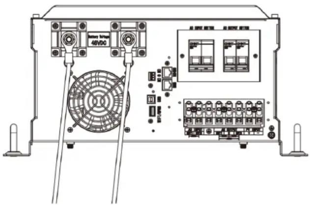
WARNING: Shock Hazard
Installation must be performed with care due to high battery voltage in series.

CAUTION!! Do not place anything between the flat part of the inverter terminal and the ring terminal. Otherwise, overheating may occur.
CAUTION!! Do not apply anti-oxidant substance on the terminals before terminals are connected tightly.
CAUTION!! Before making the final DC connection or closing DC breaker/disconnector, be sure positive (+) must be connected to positive (+) and negative (-) must be connected tonegative(-).
Lithium battery connection
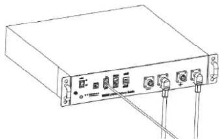
If need to communicate with lithium battery BMS, the inverter protocol should have matched the BMS first. There're two connectors on the lithium battery, RJ45 port of BMS and power cable. Please follow below steps to implement lithium battery connection:
-
Assemble battery ring terminal based on recommended battery cable and terminal size (recommended standards are in the previous page).
-
Insert the ring terminal of battery cable flatly into battery connector of inverter and make sure the bolts are tightened with torque of 2-3Nm. Make sure polarity at both the battery and the inverter/charge is correctly connected and ring terminals are tightly screwed to the battery terminals
-
Connect the end of RJ45 of battery to BMS communication port of inverter.
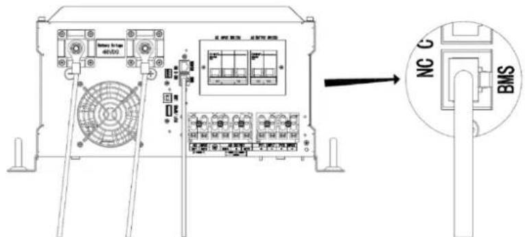
- The other end of RJ45 insert to battery comm port.
natural_image
Line drawing of a rectangular electronic device with ports and connectors (no text or symbols)Note: if choosing lithium battery, make sure to connect the BMS communication cable between the battery and the inverter. You need to choose battery type as "lithium battery".
Lithium battery communication and setting
In order to communicate with battery BMS, you should set the battery type to "LI" in Program 5. Then the LCD will switch to Program 51, which is to set the protocol type. There are several protocols in the inverter. Please get instruction from the supplier to choose which protocol to match the BMS.
1. Connect the end of RJ45 of battery to BMS communication port of inverter
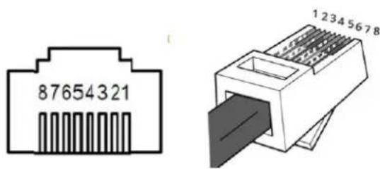
Make sure the lithium battery BMS port connects to the inverter is Pin to Pin. The BMS port supports communication with BMS by RS485 protocol or CAN protocol.
The inverter BMS port pin and RS485 port pin assignment shown as below.
| Pin number | BMS port | RS485 port (for expansion) |
| 1 | RS485B | RS485B |
| 2 | RS485A | RS485A |
| 3 | -- | -- |
| 4 | CANH | -- |
| 5 | CANL | -- |
| 6 | -- | -- |
| 7 | -- | -- |
| 8 | -- | -- |
2. LCD setting
To connect battery BMS, need to set the battery type as "LI" in Program 05.
After set "LI" in Program 05, it will switch to Program 51 to choose communication protocol. You can choose RS485 c-communication protocol which is from L01 to L50, and you can also choose CAN communication protocol which is from L51 to L99.
Note: You can only use one communication type RS485 or CAN in a time.
| 05 | Battery type | AGM (Default)AGTi OS |
| FloodFLd OS | ||
| User-DefinedUSE OSIf "User-Defined" is selected, battery charge voltage and low DC cut-off voltage can be set up in program 19, 20 and 21. | ||
| User-Defined 2(Suitable for lithium battery when no communicating with BMS)US2 OSIf 'US2' is selected, battery charge voltage and low DC cut-off voltage can be set up in program 19,20 and 21. | ||
| Lithium (Only suitable when communicate with BMS)LI OSThe lithium battery BMS communication protocol optionsLO1 S1LO2 S1LO3 S1LO4 S1...... |
When the battery type set to Li, the setting option 12, 13, 21 will change to display percent.
Note: When the battery type set as "LI", the Maximum charge current can't be modified by the user. When the communication fail, the inverter will cut off output.
| 12 | Setting SOC point back to utility source when selecting "SBU priority" or "Solar first" in program 01 | 40×12Default 40%, 5%~50% Settable |
| 13 | Setting SOC point back to battery mode when selecting "SBU priority" or "Solar first" in program 01 | 80×13Default 80%, 60%~100% Settable |
| 21 | Low DC cut-off voltage.If self-defined is selected in program 5, this program can be set up | COV 20* 2.1Default 20%, 5%~50% Settable |
AC Input/Output Connection
CAUTION!!
Before connecting to AC input power source, please install a separate AC breaker between inverter and AC input power source. This will ensure the inverter can be securely disconnected during maintenance and fully protected from over current of AC input. The recommended spec of AC breaker is 40A for 4KW\~6KW, 80A for 8KW\~12KW. There are two terminal blocks with "IN" and "OUT" markings. Please do NOT mis-connect input and output connectors.
WARNING!!
All wiring must be performed by a qualified personnel.
It's very important for system safety and efficient operation to use appropriate cable for AC input connection. To reduce risk of injury, please use the proper recommended cable size as below.
Suggested cable requirement for AC wires
| Model | Gauge | Torque Value |
| 4KW/5KW | 10 AWG | 1.4~ 1.6 Nm |
| 6KW/8KW | 8 AWG | 1.4~ 1.6 Nm |
| 10KW/12KW | 6 AWG | 1.6~ 1.8 Nm |
AC Wiring
| 240Vac outputInput:HOT1+ HOT2+GroundOutput:HOT1+ HOT2 | 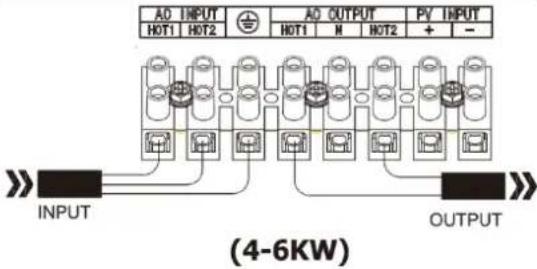 | 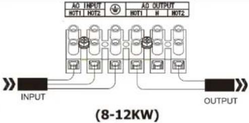 |
| 120Vac outputInput:HOT1+ HOT2+GroundOutput:HOT1+ N or HOT2+ N | 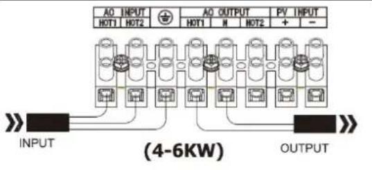 | 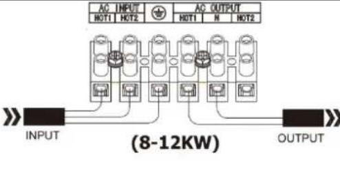 |
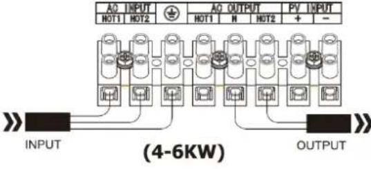 |  |
Please follow below steps to implement AC input/output connection:
- Before making AC input/output connection, be sure to open DC protector or disconnector first.
- Remove insulation sleeve 10mm for six conductors. And shorten phase L and neutral conductor N 3 mm.
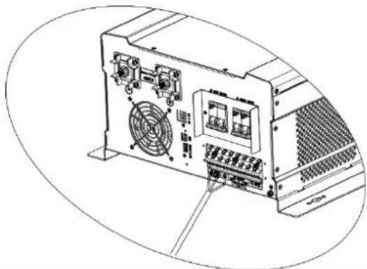
- Insert AC input wires according to polarities indicated on terminal block and tighten the terminal screws. Be sure to connect PE protective conductor first.
Hot1 --> Live wire (brown or black) Hot2 --> Live wire (brown or black) Ground --> Earth wire (yellow and green)
natural_image
Technical line drawing of a computer tower rear panel with fan and ventilation slots (no text or labels)
WARNING:
Be sure that AC power source is disconnected before attempting to hardwire it to the unit.
- Then, insert AC output wires according to polarities indicated on terminal block and tighten terminal screws.
Hot1 --> Live wire (brown or black)
N --> Neutral wire (blue)
Hot2 --> Live wire (brown or black)
natural_image
Line drawing of a computer front panel with fan, drive, and ventilation unit (no text or symbols)- Make sure the wires are securely connected.
CAUTION: Important
Be sure to connect AC wires with correct polarity. If L and N wires are connected reversely, it may cause utility short-circuited when these inverters are worked in parallel operation.
CAUTION: Appliances such as air conditioner are required at least 2\~3 minutes to restart because it's required to have enough time to balance refrigerant gas inside of circuits. If a power shortage occurs and recovers in a short time, it will cause damage to your connected appliances. To prevent this kind of damage, please check with manufacturer of air conditioner that if it's equipped with time-delay function before installation. Otherwise, this off grid solar inverter v trigger overload fault and cut off output to protect your appliance, but sometimes it still causes internal damage to the air conditioner.
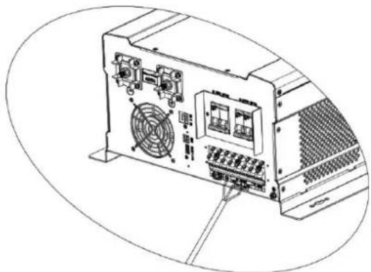
PV Connection
CAUTION: Before connecting to PV modules, please install separately a DC circuit breaker between inverter and PV modules.
WARNING! All wiring must be performed by a qualified personnel.
WARNING! It" very important for system safety and efficient operation to use appropriate cable for PV module connection. To reduce risk of injury, please use the proper recommended cable size as below.
| Model | Typical Amperage | Cable Size | Torque |
| 4KW/5KW/6KW | 80A | 8AWG | 1.6~1.8 Nm |
| 8KW/10KW/12KW | 120A | 8AWG | 1.6~1.8 Nm |
PV Module Selection:
When selecting proper PV modules, please be sure to consider below parameters:
- Open circuit Voltage (Voc) of PV modules not exceeds max. PV array open circuit voltage of inverter.
- Open circuit Voltage (Voc) of PV modules should be higher than min. batteryvoltage.
| Solar Charging Mode | ||
| INVERTER MODEL | SPF 4-12000T DVM | SPF 4-12000T DVM-MPV |
| Max. PV Array Open Circuit Voltage | 150Vdc | 250Vdc |
| PV Array MPPT Voltage Range | 60~145Vdc | 60~245Vdc |
Please follow below steps to implement PV module connection:
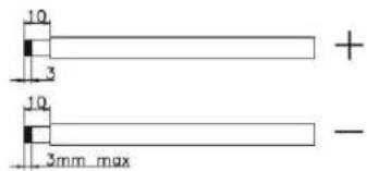
- Remove insulation sleeve 10 mm for positive and negative conductors.
- Check correct polarity of connection cable from PV modules and PV input connectors. Then, connect positive pole (+) of connection cable to positive pole (+) of PV input connector. Connect negative pole (-) of connection cable to negative pole (-) of PV input connector.
- Make sure the wires are securely connected.
PV Wiring
| 4KW/5KW/6KW, MPPT 80A | 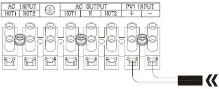 |
| 8KW/10KW/12KW, MPPT 120A | 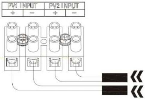 |
Communication Connection
Please use supplied communication cable to connect to inverter and PC. Follow on-screen instruction to install the monitoring software. For the detailed software operation, please check user manual of software. The monitoring software is downloadable from our website www.ginverter.com.
Dry Contact Signal
There is one dry contact (3A/250VAC) available on the rear panel. It could be used to deliver signal to generator when battery voltage reaches warning level.
- The wiring between generator and the inverter (not all generators are the same wiring diagram as below, please ask supplier for instruction if there's any questions.)
| Unit Status | Condition | Dry contact port: 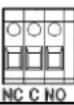 | ||
| NC & C | NO & C | |||
| Power Off | Unit is off and no output is powered. | Close | Open | |
| Power On | Output is off and no output is powered | Close | Open | |
| Battery not in "LI" mode | Battery voltage < Low DC Cut-off Voltage +2Vdc | Open | Close | |
| Detected there's AC input | Close | Open | ||
| Battery in "LI" mode | Battery SOC < Low DC Cut-off Soc +5% | Open | Close | |
| Detected there's AC input | Close | Open | ||
Electrical Performance
Inverting
Overload Capacity
- For 100%<Load<120%, Fault (Power off) after 10 seconds.
- For 120%<Load≤300%, Fault (Power off) after the 5 seconds.
Soft Start in Inverter Mode
When the inverter is turned on, the output voltage gradually ramps up from 0VAC to rated voltage in about 1.2 sec. This effectively reduces otherwise very high starting inrush current drawn by AC loads such as Switched Mode Power Supplies and inductive loads. This will result in lower motor inrush current, which means less impact on the loads and inverter.
Caution:
After the inverter is switched on, it takes a finite amount of time to self-diagnose and get ready to deliver full power. Always switch on the load(s) after a few seconds of switching on the inverter. Avoid switching on the inverter with the load already switched on. This may prematurely trigger the overload protection. When a load is switched on, it may require an initial higher power surge to start. If multiple loads are being powered, they should be switched on individually so that the inverter is not overloaded by the higher starting surge.
AC Charger
The inverter is equipped with an active PFC (power factor correction) multistage battery charger. The PFC feature is used to control the amount of power used to charge the batteries in order to obtain a power factor as close as possible to 1.
When AC voltage is in the range of 154\~260VAC, the charging current is 100%. Once it exceeds 260VAC, it must be restored to 250VAC before it can be charged.
The inverter/charger has a very rapid charge current available, and the max charge current can be adjusted from 10A to 100A in small increments on the inverter's LCD. This is helpful if this powerful charger applies charging to a small capacity battery bank.
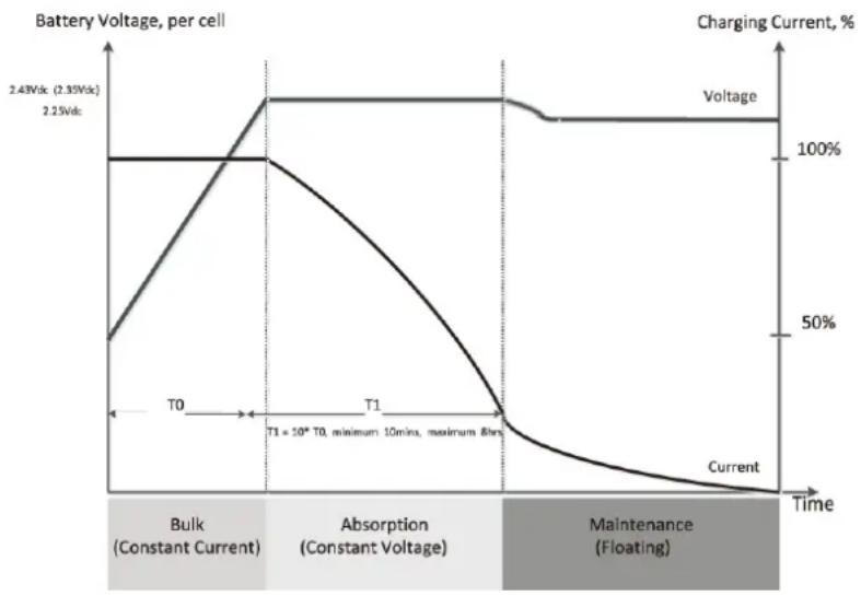
There are mainly 3 stages:
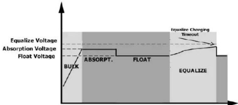
Bulk Charging: This is the initial stage of charging. While Bulk Charging, the charger supplies the battery with controlled constant current. The charger will remain in Bulk charge until the absorption charge voltage is achieved.
Absorb Charging: This is the second charging stage and begins after the absorb voltage has been reached. Absorb charging provides the batteries with a constant voltage and reduces the DC charging current in order to maintain the absorb voltage setting.
In this period, the inverter will start a T1 time; the charger will keep the boost voltage in Boost CV mode until the T1 time has run out. When charging current is <0.01C or the time is over 12 hours, then drop the voltage Down to the float voltage.
Float Charging: The third charging stage occurs at the end of the absorb charging time. During float charging, the charge voltage is reduced to the float charge voltage. In this stage, the battery are kept fully charged and ready if needed by the inverter.
line
| Time Segment | Battery Voltage (Vdc) | Charging Current (%) | | ------------------------- | --------------------- | -------------------- | | Bulk (Constant Current) | 2.43 | 100 | | Absorption (Constant Voltage) | 2.25 | 100 | | T1 | 2.25 | 100 | | T1 = 10* T0, minimum 10mins, maximum 8hrs | 2.25 | 100 | | Maintenance (Floating) | 2.25 | 100 | | Current | 2.25 | 0 |AC Charging Current:
| Model | Battery Voltage | Max. AC Charging Current |
| 4KW | 48V | 40A |
| 5KW | 48V | 50A |
| 6KW | 48V | 60A |
| 8KW | 48V | 70A |
| 10KW | 48V | 80A |
| 12KW | 48V | 100A |
MPPT Charging Current:
| Model | Battery Voltage | Max. Charging Current |
| 4-6KW | 48V | 80A |
| 8-12KW | 48V | 120A |
Battery Equalization
Equalization function is added into charge controller. It reverses the buildup of negative chemical effects like stratification, a condition where acid concentration is greater at the bottom of the battery than at the top. Equalizationalso helps to remove sulfate crystals that might have built up on the plates. If left unchecked, this condition, called sulfation, will reduce the overall capacity of the battery. Therefore, it's recommended to equalize battery periodically.
● How to Apply Equalization Function
You must enable battery equalization function in monitoring LCD setting program 23 first. Then, you may apply this function in device by either one of following methods:
-
Setting equalization interval in program 27.
-
Active equalization immediately in program 28.
- When to Equalize
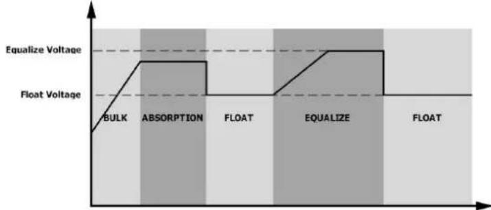
In float stage, when the setting equalization interval (battery equalization cycle) is arrived, or equalization is active immediately, the controller will start to enter Equalize stage.
line
| Stage | Voltage | | ----------- | ------- | | BULK | Low | | ABSORPTION | High | | FLOAT | Low | | EQUALIZE | High | | FLOAT | Low |● Equalize charging time and timeout
In Equalize stage, the controller will supply power to charge battery as much as possible until battery voltage raises to battery equalization voltage. Then, constant-voltage regulation is applied to maintain battery voltage at the battery equalization voltage. The battery will remain in the Equalize stage until setting battery equalized time is arrived.
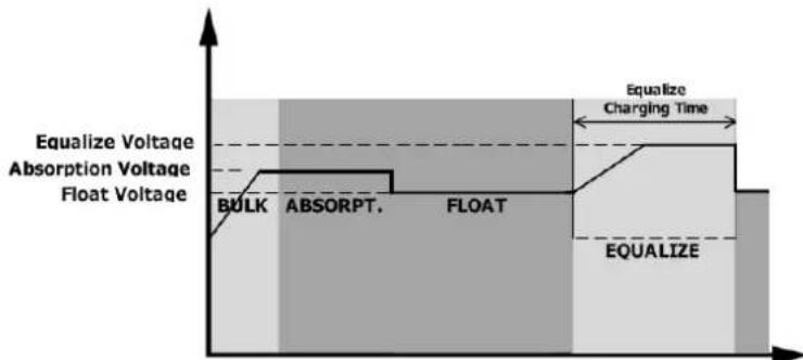
However, in Equalize stage, when battery equalized time is expired and battery voltage doesn't rise to battery equalization voltage point, the charge controller will extend the battery equalized time until battery voltage achieves battery equalization voltage. If battery voltage is still lower than battery equalization voltage when battery equalized timeout setting is over, the charge controller will stop equalization and return to float stage.
Power Saver
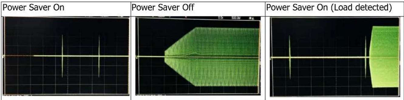
The "Power Saver" function is dedicated to conserve battery power when AC power demand is either minimal or not required at all by the loads.
In this mode, the inverter pulses the AC output looking for an AC load (i.e., electrical appliance). Whenever an AC load (greater than 500 watts at 120Vac) is turned on, the inverter recognizes the need for power and automatically starts inverting and output goes to full voltage. When there is no load (or less than 500 watts) detected, the inverter automatically goes back into search mode to minimize energy consumption from the battery bank.
In "Power saver on" mode, the inverter will draw power mainly in sensing moments, thus the idle consumption is significantly reduced.
FAN Operation
For 4-6KW models, there are one DC fan and one AC fan.
For 8-12KW models, there are one DC fans and two AC fan.
The fans are designed to operate according to the following logic:
| Condition | Enter Condition | Leave condition | Fan Speed |
| HEAT SINK TEMPERATURE | T ≤ 40°C(104°F) | T > 40°C(104°F) | OFF |
| T > 40°C(104°F) | T ≤ 40°C(104°F) | ON | |
| UTILITY CHARGER | I ≤ 20A | I>20A | OFF |
| CURRENT | I>20A | I ≤ 20A | ON |
| LOAD PERCENTAGE (INV MODE) | 20% ≤ Load | Load>20% | OFF |
| Load>20% | 20% ≤ Load | ON |
Allow at least 80CM of clearance around the inverter for air flow. Make sure that the air can circulate freely around the unit.
Output Power Derating
When DC input voltage drops to Low DC Warning Voltage OR Low DC Warning SOC, the output Voltage will be derated 10V. When transformer temperature exceed to 150°C, the output Voltage will be derated 10V.
Remote LCD Connecting (Optional)
Plug in the remote LCD panel to the RS485 port.
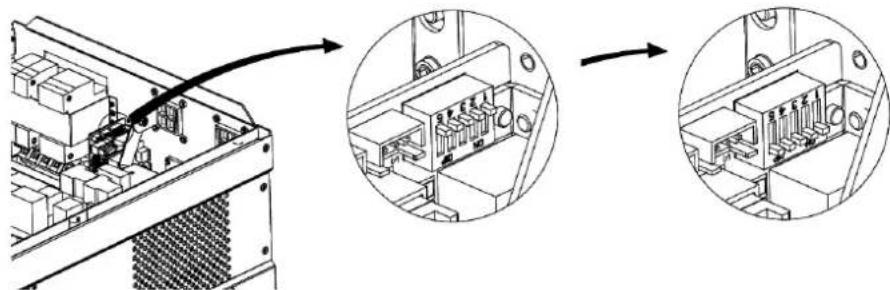
There's a DIP switch on the inverter communication board. Change the DIP switch setting to all "ON" as picture showed as below.
Warning:
Our cables are designed with special pinouts on the connectors, so don't use other cables, or the remote LCD panel will not be powered on.
Operation
Power ON/OFF
natural_image
Technical line drawing of an electronic device rear panel with labeled ports and internal components (no readable text or symbols)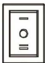
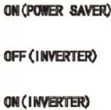
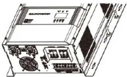
Once the unit has been properly installed and the batteries are connected well, simply press On/Off switch (located on the button of the case) to turn on the unit.
Operation and Display Panel
The operation and display panel, shown in below chart, is on the front panel of the inverter. It includes three indicators, four function keys and a LCD display, indicating the operating status and input/output power information.
- LCD display
- Status indicator
- Charging indicator
- Fault indicator
- Function buttons
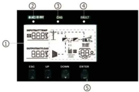
LED Indicator
| LED Indicator | Messages | ||
| AC/INV | Green | Solid On | Output is powered by utility in Line mode. |
| Flashing | Output is powered by battery or PV in battery mode. | ||
| CHG | Green | Solid On | Battery is fully charged. |
| Flashing | Battery is charging. | ||
| FAULT | Red | Solid On | Fault occurs in the inverter. |
| Flashing | Warning condition occurs in the inverter. | ||
Function Buttons
| Button | Description |
| ESC | To exit setting mode |
| UP | To go to previous selection |
| DOWN | To go to next selection |
| ENTER | To confirm the selection in setting mode or enter setting mode |
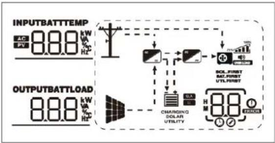
LCD Display Icons
flowchart
graph TD
    A["INPUTBATTTEMP"] --> B["AC PV 8.8 kW/Hz"]
    C["OUTPUTBATTLOAD"] --> D["8.8 kW/Hz"]
    B --> E["Charging Solar Utility"]
    D --> E
    E --> F["SOL_FIRST BAT_FIRST UTIL_FIRST"]
    F --> G["H M 8.8 / OFF"]
    F --> H["H M 100%"]
| Icon | Function Description | |
| Input Source Information | ||
| AC | Indicates the AC input. | |
| PV | Indicates the PV input | |
| INPUT8.8.8kw | Indicate input voltage, input frequency, PV voltage, battery voltage and charger current. | |
| Configuration Program and Fault Information | ||
 | Indicates the setting programs. | |
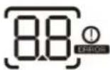 | Indicates the warning and fault codes. Warning: flashing with warning code. Warning: flashing with warning code. Fault:lighting with fault code Fault:lighting with fault code | |
| Output Information | ||
| OUTPUTBATTLOAD8.8.8kw | Indicate output voltage, output frequency, load percent, load in VA, load in Watt and discharging current. | |
| Battery Information | ||
| CHARGING | Indicates battery level by 0-24%, 25-49%, 50-74% and 75-100% in battery mode and charging status in line mode. | |
| SOLARUTILITY | These two signs indicate the charge priority. SOLAR indicates solar first. UTILITY indicate utility first. SOLAR blinking indicates solar only; SOLAR and UTILITY both on indicates combined charging. | |
| In AC mode, it will present battery charging status. | ||
| Status | Battery voltage | LCD Display |
| ConstantCurrent mode / ConstantVoltage mode | <2V/cell | 4 bars will flash in turns. |
| 2 ~ 2.083V/cell | Bottom bar will be on and the other three bars will flash in turns. | |
| 2.083 ~ 2.167V/cell | Bottom two bars will be on and the other two bars will flash in turns. | |
| >2.167 V/cell | Bottom three bars will be on and the top bar will flash. | |
| Floating mode. Batteries are fully charged. | 4 bars will be on. | |
In battery mode, it will present battery capacity.
| Load Percentage | Battery Voltage | LCD Display |
| Load >50% | < 1.717V/cell |  |
| 1.717V/cell ~ 1.8V/cell |  | |
| 1.8 ~ 1.883V/cell |  | |
| > 1.883 V/cell |  | |
| 50%> Load > 20% | < 1.817V/cell |  |
| 1.817V/cell ~ 1.9V/cell |  | |
| 1.9 ~ 1.983V/cell |  | |
| > 1.983 |  | |
| Load < 20% | < 1.867V/cell |  |
| 1.867V/cell ~ 1.95V/cell |  | |
| 1.95 ~ 2.033V/cell |  | |
| > 2.033 |  |
Load Information
| OVER LOAD | Indicates overload. | |||
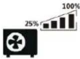 | Indicates the load level by 0-24%, 25-49%, 50-74% and 75-100%. | |||
| 0%~24% | 25%~49% | 50%~74% | 75%~100% | |
 |  |  | 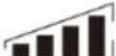 | |
| Mode Operation Information | ||||
 | Indicates unit connects to the mains. | |||
 | Indicates unit connects to the PV panel. | |||
 | Indicates load is supplied by utility power. | |||
 | Indicates the utility charger circuit is working. | |||
 | Indicates the DC/AC inverter circuit is working. | |||
 | These three sins indicate the output priority. SOL.FIRST indicates solar first. BAT.FIRST indicates battery first. UTI.FIRST indicates utility first. | |||
| Mute Operation | ||||
 | Indicates unit alarm is disabled. | |||
LCD Setting
After pressing and holding ENTER button for 3 seconds, the unit will enter setting mode. Press "UP" or "DOWN" button to select setting programs. And then, press "ENTER" button to confirm the selection or ESC button to exit.
Setting Programs:
| Program | Description | Setting Option | |
| 01 | Output source priority:To configure loadpower source priority | Solar first |   |
| Solar energy provides power to the loads as first priority.If solar energy is not sufficient to power all connected loads,battery energy will supply power the loads at the same time.Utility provides power to the loads only when any one conditionhappens:- Solar energy is notavailable- Battery voltage drops toeither low-level warning voltage orthesetting point in program12. | |||
| Utility first (default) |   | ||
| Utility will provide power to the loads as first priority.Solar and battery energy will provide power to the loads onlywhen utilitypower is not available. | |||
| SBU priority |   | ||
| Solar energy provides power to the loads as first priority.If solar energy is not sufficient to power all connected loads,battery energy will supply power to the loads at the same time.Utility provides power to the loads only when battery voltagedrops to either low-level warning voltage or thesetting point inprogram 12. | |||
| 02 | Maximum chargingcurrent: To configure totalcharging current for solarand utility chargers.(Max. charging current =utility charging current +solar charging current) |   12KW model: default 80A, 10A~180A Settable10KW model: default 80A, 10A~160A Settable8KW model: default 80A, 10A~150A Settable6KW model: default 80A, 10A~140A Settable5KW model: default 80A, 10A~130A Settable4KW model: default 80A, 10A~120A Settable(If Li is selected in program 5, this program can't be set up) 12KW model: default 80A, 10A~180A Settable10KW model: default 80A, 10A~160A Settable8KW model: default 80A, 10A~150A Settable6KW model: default 80A, 10A~140A Settable5KW model: default 80A, 10A~130A Settable4KW model: default 80A, 10A~120A Settable(If Li is selected in program 5, this program can't be set up) | |
| 03 | AC input voltage range | 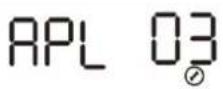 Appliance (default) Appliance (default) | If selected, acceptable AC input voltage range will be within 154~272VAC |
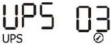 | If selected, acceptable AC input voltage range will be within 184~272VAC | ||
| 05 | Battery type | AGM (Default) | |
Flood | |||
User-Defined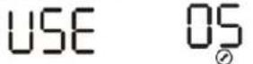 If "User-Defined" is selected, battery charge voltage and low DC If "User-Defined" is selected, battery charge voltage and low DC set up in program 19, 20 and 21. set up in program 19, 20 and 21. | |||
User-Derined Z(Suitable for lithium battery when no communicating with BMS) If 'US2' is selected, battery charge voltage and low DC cut-off voltage can be set up in program 19,20 and 21. If 'US2' is selected, battery charge voltage and low DC cut-off voltage can be set up in program 19,20 and 21. | |||
 hen communicate with BMS)11 OS hen communicate with BMS)11 OS communication protocol optionsLO1 S1 communication protocol optionsLO1 S1 LO3 S1 LO3 S1 | |||
| 06 | Auto restart when overload occurs | Restart disable (default)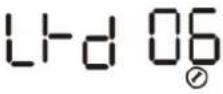 | Restart enable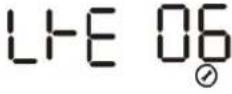 |
| 08 | Output voltage | 230V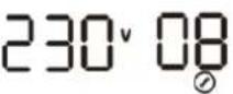 | 220V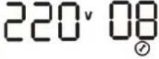 |
240V(default)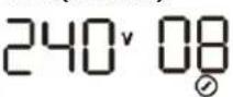 | 208V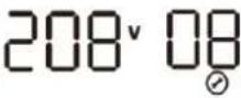 | ||
| 09 | Output frequency | 50Hz (default)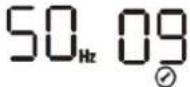 | 60Hz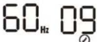 |
| 11 | Maximum utility charging current | 30^ 1112KW model: default 30A, 10A~100A Settable10KW model: default 30A, 10A~80A Settable8KW model: default 30A, 10A~70A Settable6KW model: default 30A, 10A~60A Settable5KW model: default 30A, 10A~50A Settable4KW model: default 30A, 10A~40A Settable(If Li is selected in program 5, this program can't be set up) | |
| 12 | Setting voltage point back to utility source when selecting "SBU priority" or "Solar first" in program 01 | 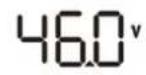  48V model: default 46.0V, 44.0V~51.2V settable 48V model: default 46.0V, 44.0V~51.2V settable | |
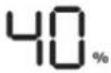  48V model Lithium mode: default 40%, 5%~50% settable 48V model Lithium mode: default 40%, 5%~50% settable | |||
| 13 | Setting voltage point back to battery mode when selecting "SBU priority" or "Solar first" in program 01 | 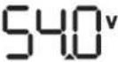  48V model: default 54.0V, 48.0V~58.0V Settable 48V model: default 54.0V, 48.0V~58.0V Settable | |
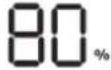  48V model Lithium mode: default 80%, 60%~100% settable 48V model Lithium mode: default 80%, 60%~100% settable | |||
| 14 | Charger source priority: To configure charger source priority | If this off grid solar inverter is working in Line, Standby or Faultmode, charger source can be programmed as below: | |
| Solar firstCSO 14∅ | Solar energy will charge battery as first priority.Utility will charge battery only when solar energy is not available. | ||
| Utility firstCUT 14∅ | Utility will charge battery as first priority.Solar energy will charge battery only when utility power is not available. | ||
| Solar and Utility (Default)SNU 14∅ | Solar energy and utility will both charge battery. | ||
| Only SolarOSO 14∅ | Solar energy will be the only chargersource no matter utility is available or not. | ||
| If this off grid solar inverter is working in Battery mode or Power saving mode, only solar energy can charge battery. Solar energy will charge battery if it's available and sufficient. | |||
| 15 | Alarm control | Alarm on (default)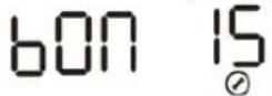 | Alarm off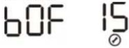 |
| 16 | Backlight control | Backlight on (default)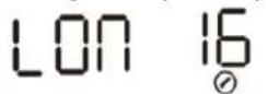 | Backlight off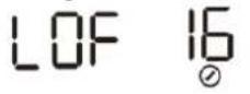 |
| 17 | Beeps while primary source is interrupted | Alarm on (default)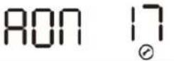 | Alarm off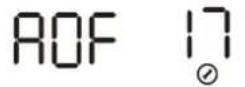 |
| 19 | C.V. charging voltageIf self-defined is selected in program 5, this program can be set up | 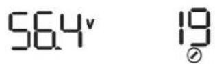 48V model: default 56.4V, 48.0V~58.4V Settable 48V model: default 56.4V, 48.0V~58.4V Settable | |
| 20 | Floating charging voltage.If self-defined is selected in program 5, this program can be set up |  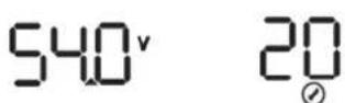 48V model: default 54.0V, 48.0V~58.4V Settable 48V model: default 54.0V, 48.0V~58.4V Settable | |
| 21 | Low DC cut-off voltage.If self-defined is selected in program 5, this program can be set up | 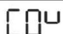 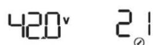 48V model: default 42.0V, 40.0V~48.0V Settable 48V model: default 42.0V, 40.0V~48.0V Settable | |
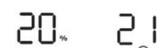 48 model Lithium mode: default 20%, 5%~50% Settable 48 model Lithium mode: default 20%, 5%~50% Settable | |||
| 22 | RS485communication address |  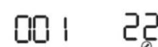 Default 001,001-255 Settable Default 001,001-255 Settable | |
| 23 | Battery equalization |  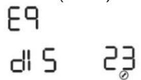 | Enable   |
| If "Flooded" or "User-Defined" is selected in program this program can be set up. | |||
| 24 | Battery equalization voltage | 48V model: default 58.4V, 48~60V Settable 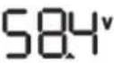  | |
| 25 | Battery equalized time | Setting range is from 5 minutes to 900 minutes. Increment of each click is 1 minute 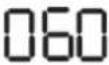  | |
| 26 | Battery equalized timeout | Setting range is from 5 minutes to 900 minutes. Increment of each click is 1 minute   | |
| 27 | Equalization interval | Setting range is from 1 day to 30 days. Increment of each click is 1 day 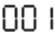  | |
| 28 | Equalization activated immediately | Disabled (Default)   | Enable   |
| If equalization function is enabled in program 23, this program can be set up. If "Enable" is selected in this program, it's to activate battery equalization immediately and LCD main page will shows "C". If "Disable" is selected, it will cancel equalization function until next activated equalization time arrives based on program 27 setting. At this time, "C" will not be shown in LCD main page. | |||
Display Information
The LCD display information will be switched in turns by pressing "UP" or "DOWN" key. The selectable information is switched as below order: input voltage, input frequency, PV voltage, MPPTcharging current, MPPT charging power, battery voltage, output voltage, output frequency, load percentage, load in VA, load in Watt, DC discharging current, main CPU Version and second CPU Version.
| Setting Information | LCD display |
| Input voltage/ Output voltage(Default Display Screen) | Input Voltage=230V, output voltage=230V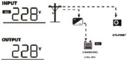 |
| Input frequency | Input frequency=50Hz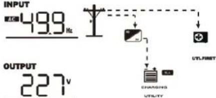 |
| AC charging current | AC charging current=30A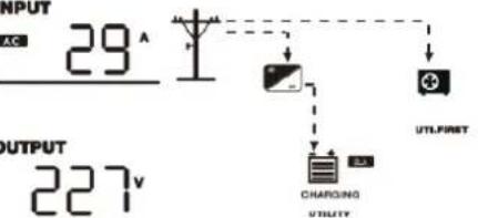 |
| PV voltage | PV voltage=103V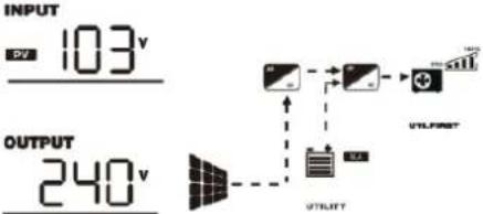 |
| PV charging current | PV charging current=50A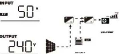 |
| PV charging power | MPPT charging power=1.68KWBATT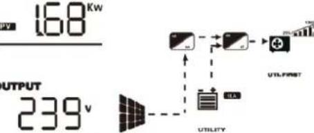 |
| PV and utility charging current | Current=140A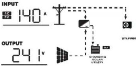 |
| Output frequency | Output frequency=50Hz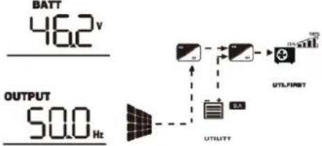 |
| Load percentage | Load percent=92%BATT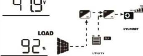 |
| Load in VA | When connected load is lower than 1kVA, load in VA will present xxxVA like below chart.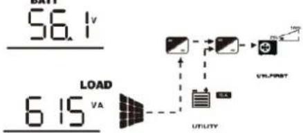 When load is larger than 1kVA (≥1KVA), load in VA will present x.xkVA like below chart. When load is larger than 1kVA (≥1KVA), load in VA will present x.xkVA like below chart.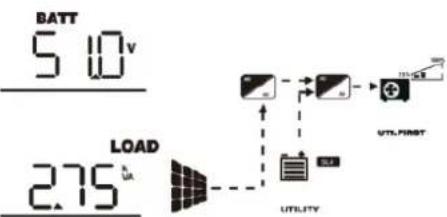 |
| Load in Watt | When connected load is lower than 1kW, load in W will present xxx W like below chart.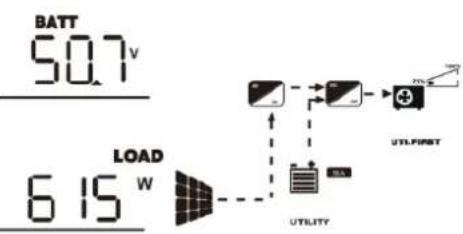 |
| Load in Watt | When load is larger than 1kW (≥1KW), load in W will present x.xkW like below chart.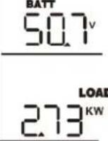 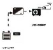 |
| DC discharging current | DC discharging current=128A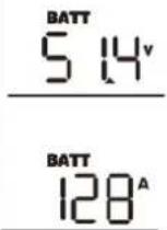 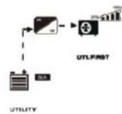 |
| Main CPU version checking | Main CPU version 028-00-505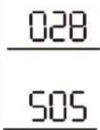 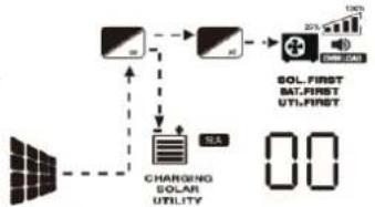 |
| Secondary CPU version checking | Secondary CPU version 029-00-409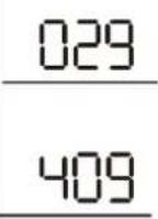 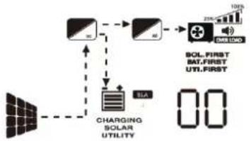 |
| Inverter Rated Power | 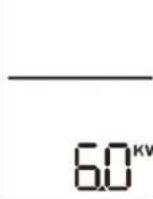 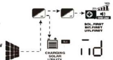 |
| Battery level | Battery SOC=50%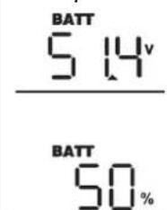 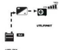 |
| Battery Equalization | 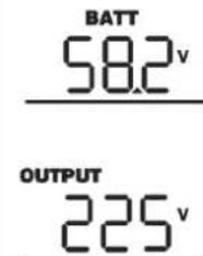 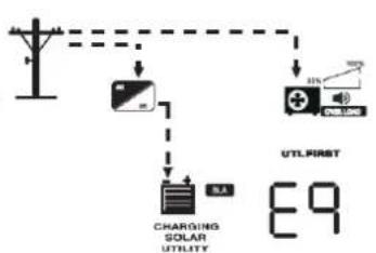 |
Operating Mode Description
| Operation mode | Description | LCD display |
| Standby mode /Power saving modeNote:*Standby mode: The inverter is not turned on yet but at this time, the inverter can charge battery without AC output. | No output is supplied by PV still can charge batteries. | When utility grid connected, no charging; PV can charge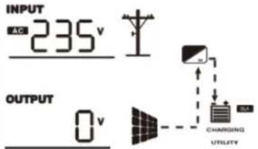 |
| Line Mode | Priority for utility drive the loading solar priority charging | Charging by PV energy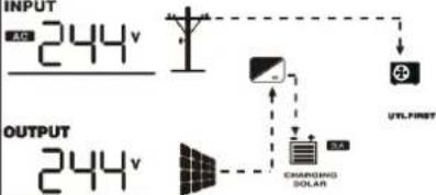 |
| The unit will provide output power from the mains. It will also charge the battery at line mode. | Charging by utility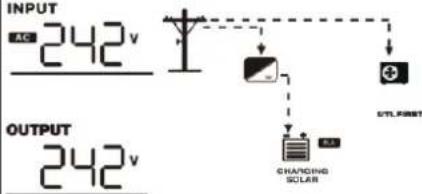 | |
| Battery Mode | The unit will provide output power from battery and PV power. | Power from battery and PV energy.BATT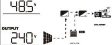 |
Power from battery only.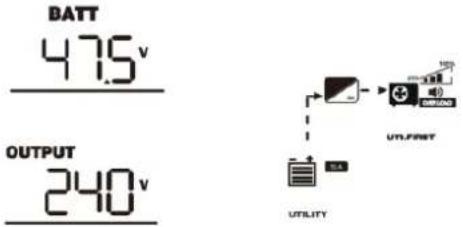 |
Fault Reference Code
| Fault Code | Fault Event | Icon on |
| 01 | Fan is not working. | |
| 02 | Over temperature | |
| 03 | Battery voltage is too high | |
| 05 | Output short circuited | |
| 06 | Output voltage is abnormal.Output voltage is too high. | |
| 07 | Overload time out | |
| 20 | BMS communication loss | |
| 51 | Over current or surge |
Warning Indicator
| Warning Code | Warning Event | Audible Alarm | Icon flashing |
| 01 | MPPT PCB Fan Abnormal | Beep twice every second |  |
| 03 | High Battery Voltage | Beep twice every second |  |
| 04 | Battery low voltage/Battery SOC low | Beep twice every second |  |
| 07 | Overload In Inverter Mode | Beep twice every second |  |
| 12 | Solar controller over temperature | Beep once every second |  |
| 51 | Solar Charger Over Current | Beep once every second |  |
| 54 | PV input over voltage | Beep once every second |  |
| 58 | AC output low voltage | Beep once every second | 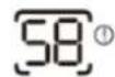 |
| 61 | Sampling error of battery voltage detecting is over 0.5V | Beep once every second |  |
Trouble Shooting
| Problem | LCD/LED/Buzzer | Explanation / Possible cause | What to do |
| Unit shuts down automatically during startup process. | LCD/LEDs and buzzer will be active for 3 seconds and then complete off. | The battery voltage is too low (<1.91V/Cell) | 1. Re-charge battery.2. Replace battery. |
| No response after power on. | No indication. | 1. The battery voltage is far too low. (<1.4V/Cell)2. Battery polarity is connected reversed. | 1. Check if batteries and the wiring are connected well.2. Re-charge battery.3. Replace battery. |
| Buzzer beeps continuously and red LED is on. | Fault code 01 | Fan fault | Replace the fan. |
| Fault code 02 | Internal temperature of component is over 90°C. | Check if the air flow of the unit is blocked or the ambient temperature is too high. | |
| Fault code 03 | Battery is over-charged. | Return to repair center. | |
| The battery voltage is too high. | Check if spec and quantity of batteries are meet requirements. | ||
| Fault code 04 | The battery voltage is too low. | ||
| Fault code 05 | Output short circuited. | Check if wiring is connected well and remove abnormal load. | |
| Fault code 06/58 | Output abnormal (Inverter voltage below than 180Vac or is higher than 290Vac) | 1. Reduce the connected load.2. Return to repair center | |
| Fault code 07 | Overload error. The inverter is overload 110% and time is up. | Reduce the connected load by switching off some equipment. | |
| Fault code 20 | BMS communication failed | 1. Check the BMS communication wire to see if it's well connected2. Check the transceiver signal | |
| Fault code 51 | Over current or surge | Restart the unit, if the error happens again, please return to repair center. |
Specifications
| MODEL | SPF 4000T DVM | SPF 5000T DVM | SPF 6000T DVM | SPF 8000T DVM | SPF 10000T DVM | SPF 12000T DVM |
| Battery voltage | 48VDC | 48VDC | 48VDC | 48VDC | 48VDC | 48VDC |
| INVERTER OUTPUT | ||||||
| Rated Power | 4KW | 5KW | 6KW | 8KW | 10KW | 12KW |
| Surge Rating (20ms) | 12KW | 15KW | 18KW | 24KW | 30KW | 36KW |
| Waveform | Pure sine wave/ same as input (bypass mode) | |||||
| Nominal Output Voltage | 104V-110V-115V-120Vac / 208V-220V-230V-240Vac(+/-10% RMS) | |||||
| Output Frequency | 50Hz/60Hz (+/-0.3 Hz) | |||||
| Inverter Efficiency(Peak) | >85% | |||||
| Line Mode Efficiency | >95% | |||||
| Power Factor | 1.0 | |||||
| SOLAR CHARGER | ||||||
| Maximum PV Charge Current | 80A | 120A | ||||
| DC Voltage | 48V | |||||
| Maximum PV Array Power | 5000W | 7000W | ||||
| MPPT Operating Voltage(VDC) | 60-145V | |||||
| Max. PV Array Open Circuit Voltage | 150VDC | |||||
| Maximum Efficiency | 97.5% | |||||
| DC Input | ||||||
| Low DC Cut-Off Voltage (Only Lead Acid) | Default @load<20%: 42.0V; @20%≤load<50%: 40.8V; @load≥50%: 38.4V (Based on Program 21, 40Vdc~48Vdc settable) | |||||
| Low DC Warning Voltage (Only Lead Acid) | Low DC Cut-Off Voltage +2Vdc | |||||
| Low DC Warning Return Voltage (Only Lead Acid) | >48V | |||||
| Low DC Warning SOC (Only Li) | <Low DC Cut-off SOC +5% | |||||
| Low DC Warning Return SOC (Only Li) | >Low DC Cut-off SOC +15% | |||||
| Low DC Cut-off SOC (Only Li) | Default 20%, 5%~50% Settable | |||||
| Cold Start SOC (Only Li) | >Low DC Cut-off Soc+10% | |||||
| High DC Recovery Voltage | 58VDC | |||||
| High DC Cut-Off Voltage | AGM:60V, FLD:62V, USE or Li Mode: C.V. Voltage + 4.0V | |||||
| AC INPUT | ||||||
| Voltage | 240VAC | |||||
| Selectable Voltage Range | 154~272VAC(for appliances ), 184~272VAC(for UPS) | |||||
| Frequency Range | 50Hz/60Hz (Auto sensing) | |||||
| Maximum Charge Current | 40A | 50A | 60A | 70A | 80A | 100A |
| BYPASS & PROTECTION (Grid & Generator) | ||||||
| Typical Transfer Time | 10ms | |||||
| Overload Protection (SMPS Load) | Circuit breaker | |||||
| Output Short Circuit Protection | Circuit breaker | |||||
| MECHANICAL SPECIFICATIONS | ||||||
| Dimensions (W*H*D) | 540*360*218mm | 650*380*225mm | ||||
| Net Weight (kg) | 38 | 41 | 45 | 64 | 66 | 75 |
| OPERATING ENVIRONMENT | ||||||
| Operation Temperature Range | 0°C to 50°C | |||||
| Storage Temperature | -20°C to 60°C | |||||


- Information on this Manual ....1
- Introduction......2
- Installation....4
- Operation 15
- Trouble Shooting....28
- Specifications 29
- Information on this Manual
- Validity
- Scope
- Target Group
- Safety Instructions
- WARNING: This chapter contains important safety and operating instructions. Read and keep this manual for future reference.
- Introduction
- Features
- Installation
- Unpacking and Inspection
- Preparation
- Mounting the Unit
- Battery Connection
- WARNING: Shock Hazard
- Lithium battery connection
- Lithium battery communication and setting
- Connect the end of RJ45 of battery to BMS communication port of inverter
- LCD setting
- AC Input/Output Connection
- CAUTION!!
- WARNING!!
- WARNING:
- CAUTION: Important
- PV Connection
- PV Module Selection:
- PV Wiring
- Communication Connection
- Dry Contact Signal
- Electrical Performance
- Inverting
- Overload Capacity
- Soft Start in Inverter Mode
- Caution:
- AC Charger
- Battery Equalization
- ● How to Apply Equalization Function
- - When to Equalize
- ● Equalize charging time and timeout
- Power Saver
- FAN Operation
- Output Power Derating
- Remote LCD Connecting (Optional)
- Operation
- Power ON/OFF
- Operation and Display Panel
- LCD Display Icons
- LCD Setting
- Display Information
- Fault Reference Code
- Warning Indicator
Brand : Growatt
Model : SPF 6000-18000T -MPV
Category : Uncategorized