
SEM-X - Uncategorized Growatt - Free user manual and instructions
Find the device manual for free SEM-X Growatt in PDF.


| Product Type | Smart Array Communication Box (Anti-backflow Box) |
| Model | ShineSEM-XA-R (SEM-X series) |
| Brand | Growatt |
| Dimensions (H x W x D) | 352 x 430 x 109 mm |
| Weight | 8.7 kg |
| Ingress Protection | IP66 |
| Operating Temperature Range | -30°C to +60°C |
| Relative Humidity | 5% to 95% (non-condensing) |
| Maximum Operating Altitude | 4000 m |
| Input Voltage (Rated) | 400 Vac (3W/N/PE) |
| Input Frequency | 50/60 Hz |
| Maximum Detection Current (CT Primary) | 250 A / 600 A / 1200 A / 2000 A / 4000 A (depending on system capacity) |
| Input Current (CT Secondary) | 5 A |
| Current Detection Accuracy | 0.5% or 0.2% (depending on CT) |
| Communication Interfaces | RS485, Ethernet (LAN), 4G (optional) |
| Maximum Number of Inverters Connected | 48 units |
| Maximum Communication Distance (RS485) | 500 m (twisted-pair shielded cable) |
| Maximum Communication Distance (Ethernet) | 50 m |
| Grid Connection Type | Three-phase four-wire (3W/N/PE) |
| Power Adjustment Modes | Total Phase, Minimum Phase, Single Phase (for storage inverters) |
| Working Modes (Storage Inverter) | Load First, Battery First, Grid First, PV-only Storage, Battery Idle, Standby |
| Third-Party Server Support | MODBUS TCP, IEC104 (limited or unlimited) |
| Standards Met | CE, RoHS |
Frequently Asked Questions - SEM-X Growatt
User questions about SEM-X Growatt
0 question about this device. Answer the ones you know or ask your own.
Ask a new question about this device
Download the instructions for your Uncategorized in PDF format for free! Find your manual SEM-X - Growatt and take your electronic device back in hand. On this page are published all the documents necessary for the use of your device. SEM-X by Growatt.
USER MANUAL SEM-X Growatt
ShineSEM-XA-R Operation Manual V1.0
CONTENT
1 About this manual ....1
1.1 Manual Description .... 1
1.2 Copyright Notice .... 1
1.3 Applicable personnel .... 1
1.4 Manual usage.... 1
2 Product introduction and installation .... 2
2.1 Product appearance and internal structure.... 2
2.1.1 Appearance.... 2
2.1.2 Internal structure 3
2.2 Introduction to working principle 6
2.3 Unpacking 7
2.4 Installation....7
2.5 Wiring instructions 8
2.6 Cable Specifications.... 11
3 Operation and application.... 12
3.1 ShineMaster4G-X operation introduction.... 12
3.1.1 Access ShineMaster4G-X built-in page.... 12
3.1.2 Login 13
3.1.3 ShineMaster4G-X data collector system information 14
3.1.4 ShineMaster4G-X collector settings 15
3.1.5 ShineMaster4G-X network settings 19
3.1.6 Power adjustment settings.... 22
3.1.7 Third-party server configuration 27
3.1.8 Power plant relationship configuration....28
3.1.9 Precautions for operation on the configuration page 29
4 Specification parameters and model description 30
4.1 Specification parameters 30
4.2 Model description.... 31
5 contact us.... 32
1 About this manual
1.1 Manual description
Dear user, thank you for using the ShineSEM-XA-R developed and produced by Shenzhen Growatt New Energy Co., Ltd. (hereinafter referred to as Growatt).
Performance and functionality make more comments. The purpose of this manual is to provide users with detailed product information and instructions for installation, operation and maintenance.
1.2 Copyright notice
The copyright of this user manual is owned by Growatt. No part or all of this user manual may be excerpted, reproduced or transmitted in any form, including information and publications, by any entity or individual without our written permission. Infringement of which will be prosecuted.
The version number of this manual is V1.0. Growatt has the final right to interpret this user manual. In case of changes in product parameters, appearance, packaging, etc., the latest information of the company shall prevail without prior notice.
1.3 Applicable personnel
This manual is intended for technical professionals who install, commission and maintain the ShineSEM-XA-R and for users who carry out routine operations. If necessary, please refer to the appropriate user information from Growatt.
1.4 Manual usage
Please read this manual carefully before installing and using the smart array communication box. Also, keep this manual in a safe place where it can be easily found by operating and maintenance personnel. The contents of this manual are subject to constant updating and correction and there will inevitably be minor discrepancies or errors with the actual product. Users are advised to refer to the actual product purchased, and can download the latest user manual through oss.growatt.com, or obtain the latest user manual through Growatt's sales or service channels.
introduction and installation 2
Product
2.1 Product appearance and internal structure
2.1.1 Appearance
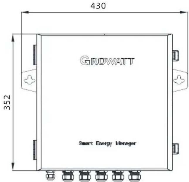
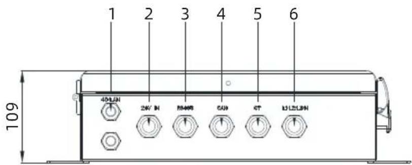
Figure 2-1 Appearance (unit: mm)
| Serial number | Label | Illustrate |
| 1 | 4G/LAN | 4G antenna/Network cable interface |
| 2 | 24V IN | 24V interface |
| 3 | RS485 | Rs485 interface |
| 4 | CAN | CAN bus interface |
| 5 | CT | CT interface |
| 6 | L1/L2/L3 | Three-phase voltage interface |
2.1.2 Internal structure
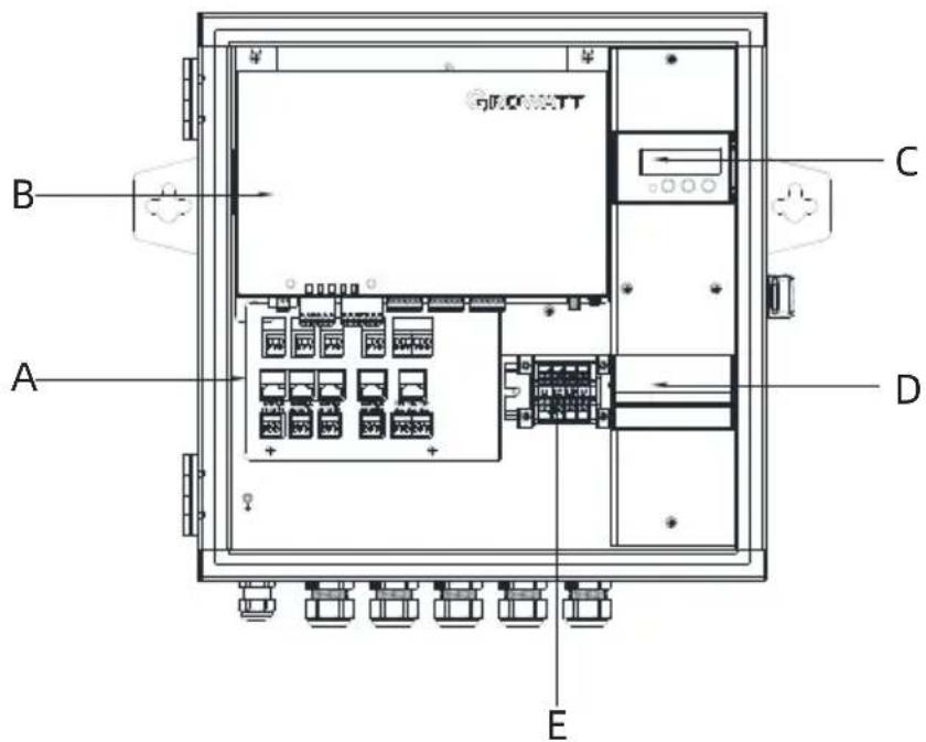
Figure 2-2 Internal structure
| Serial number | Illustrate |
| A | interface converter |
| B | ShineMaster4G-X Collect |
| C | Meter |
| D | Air disconnect switch |
| E | Terminals |
The ShineSEM-XA-R is mainly composed of ShineMaster4G-X, electric meter, air isolating switch, and terminal block
The functions of each part are as follows:
-
ShineMaster4G-X: the control core, which communicates with the inverter and the meter to realize the functions of remote monitoring, setting, upgrading, and collecting relevant operating information of the inverter.
-
Electric meter: Real-time monitoring of parameters such as voltage, current and power.
-
Air isolation switch: It can control the start and stop of ShineMaster4G-X.
-
Terminal block: where the user makes connections.
2.1.2.1 ShineMaster status LED light
ShineMaster4G-X status LED lights, which can display the running status of ShineMaster4G-X.
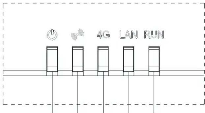
A B C D E
Figure 2-3 Indicator lights
| Indicator light | Meaning |
| A. Power indicatorPower LED | Always off: The power supply is working abnormally;Steady on: The power supply is working normally. |
| B.Bluetoothindicator BLE LED(not currently supported) | Always off: Bluetooth is not enabled;1S blinks 1 time, off 1 time: Bluetooth is enabled, but not connected to the mobile APP;Steady on: Bluetooth works normally and is connected to the mobile APP normally. |
| C.4G indicator4G LED | Always off: does not support 4G function;1S blinks 2 times, off 1 time: no SIM card inserted1S blinks 1 time, off 1 time: 4G network is abnormal or SIM has no traffic;Steady on: The 4G network is normal. |
| D.LAN indicatorLAN LED | Always off: the network is not connected;1S blinks 1 time, off 1 time: Obtained a valid IP, no network data interaction. That is, the connection with the server is abnormal. |
| E.Status IndicatorRUN LED | Steady off: The system is working normally without any alarm or fault;Blinking blue light: the system has an alarm; for example:abnormal connection to the server, abnormal communication of monitoring equipment, etc.Steady red light: There is a system failure. For example:The SD card is not working properly. The MMC memory chip is not working properly. The anti-backflow function fails.Lightning protection alarm, third-party alarm signal, etc. |
2.1.2.2 Air isolating switch
The switch is switched off by default at the factory. The power meter and ShineMaster4G-X are in a powered off state. The power meter and ShineMaster4G-X work properly when powered up.
2.1.2.3 Wiring terminal block
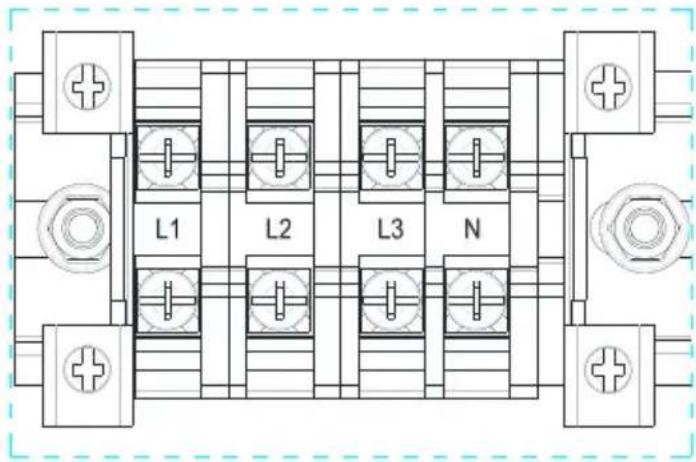
Figure 2-4 Terminal block
4 wiring ports in the terminal block, which are as follows from left to right:
(a) Three-phase voltage output interface (L 1, L 2, L 3)
(b) Single-phase power input interface (L, N)
2.1.2.4 Electric surface panel
The ammeter is an optional component, and it is used with the anti-reflux box
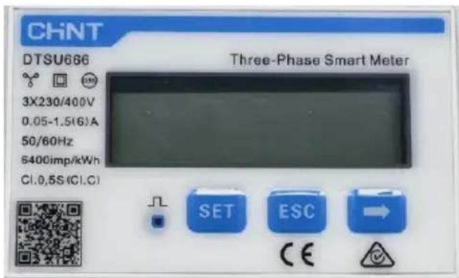
Figure 2-5 Electrometer panel
The electrical panel can display various electrical parameters: voltage, current, active energy, active power, power factor, etc. The display interface and setting parameters can be switched through the 3 buttons at the bottom of the panel, click "→" to switch to the next interface, and click "ESC" to switch to the previous interface, see chapter 3.3 for details.
2.1.2.5 Current transformer
The ShineSEM-XA-R with different system capacities will be delivered with different types of open-type current transformers, which are used to detect the current of the grid-connected access point in the low-voltage power distribution system. The specifications are shown in the following table:
| System capacity | Current ratio | Precision | Core turns | Dimensions (mm) W*H*D | Perforation size (mm) a*e |
| 100KW | 250/5A | 0.5 | 1 | 90*114*40 | 22*32 |
| 300KW | 600/5A | 0.5 | 1 | 114*140*36 | 42*62 |
| 600KW | 1200/5A | 0.5 | 1 | 144*199*36 | 82*122 |
| 1MW | 2000/5A | 0.5 | 1 | 184*254*52 | 82*162 |
| 2MW | 4000/5A | 0.2 | 1 | 184*254*52 | 82*162 |
Note:
- The total power of inverters or loads in the entire system cannot exceed the corresponding system capacity of the ShineSEM-XA-R.
- Under any conditions, the current flowing through the primary side of the current transformer (CT) cannot exceed its maximum detection range.
- Avoid running the current transformer in high-humidity environment.
2.2 Introduction to working principle
The working principle of the smart array communication box is as follows:
- The inverter converts the direct current generated by sunlight irradiating the photovoltaic string into alternating current,
- The electric energy generated by the inverter can be used for user load or output to the grid,
- The ShineSEM-XA-R is located between the inverter, the user load and the grid, and communicates with the inverter through RS485.
The block diagram of photovoltaic grid-connected anti-backflow system is as follows:

flowchart
graph LR
    A["Grid Connection"] --> B["Air Conditioner"]
    B --> C["Electric meters"]
    C --> D["Ducturing Unit"]
    D --> E["Pump Transmission Line"]
Figure 2-6 Photovoltaic grid-connected anti-backflow system
| Symbol | Illustrate | Symbol | Illustrate |
| A | Photovoltaic string | B | inverter |
| C | Load | D | Wisdom Subarray Communication Box |
| E | power grid |
2.3 Unpacking
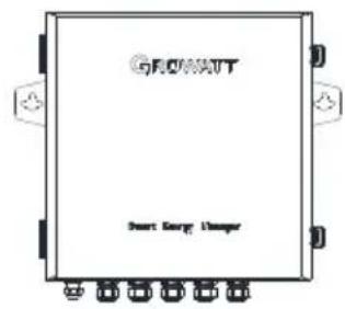
The main accessories of the smart array communication box are as follows:
A
B
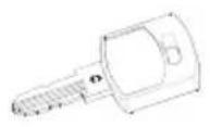
C

D

E
Figure 2-7 Accessory diagram
| Serial number | Describe | Quantity |
| A | ShineSEM-XA-R | 1 |
| B | Installation Manual | 1 |
| C | Case key | 2 |
| D | Expansion screw | 3 |
| E | Set screw | 1 |
2.4 Installation
Referring to the drawing method in the figure below, drill two holes in the wall and insert the plastic expansion tubes, lock the self-tapping screws on the plastic expansion tubes, fix the fixed wall hanging of the ShineSEM-XA-R to the wall, and then install the Hang up the communication box of the smart sub-array, and lock the screws to complete the installation.
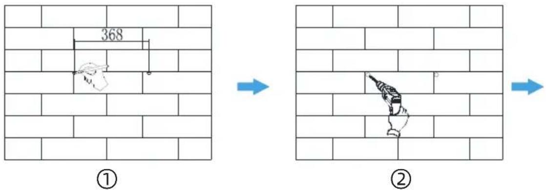
Figure 2-8 Pointing and punching
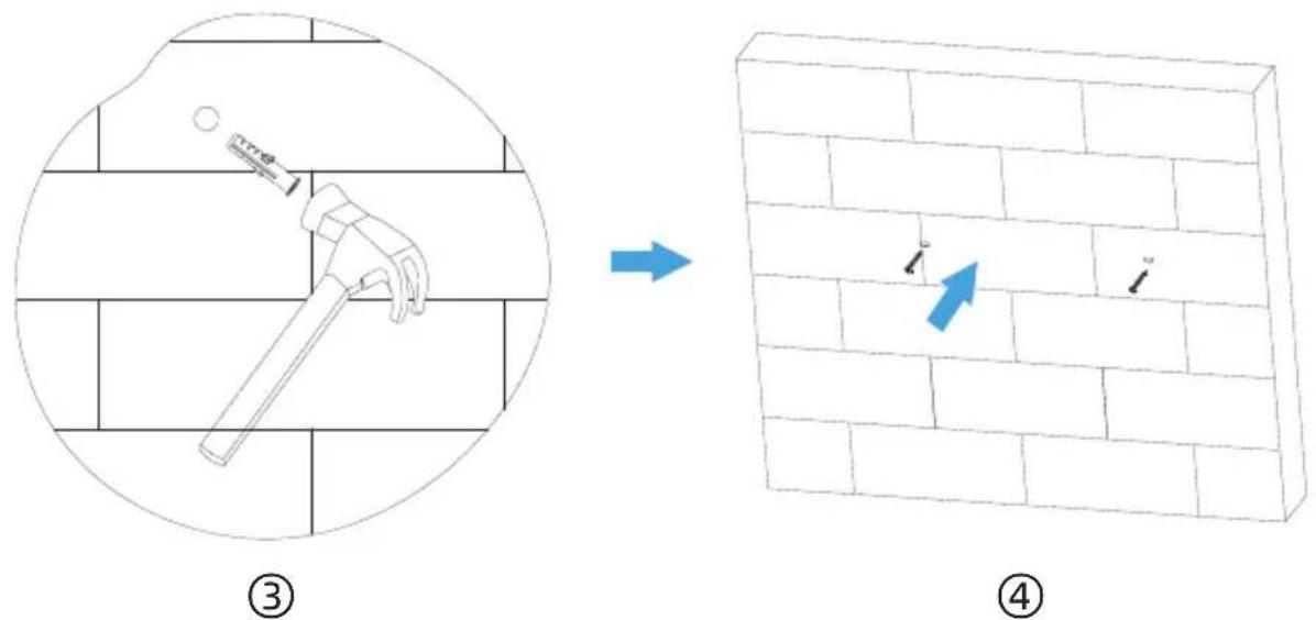
Figure 2-9 Install Expansion screw
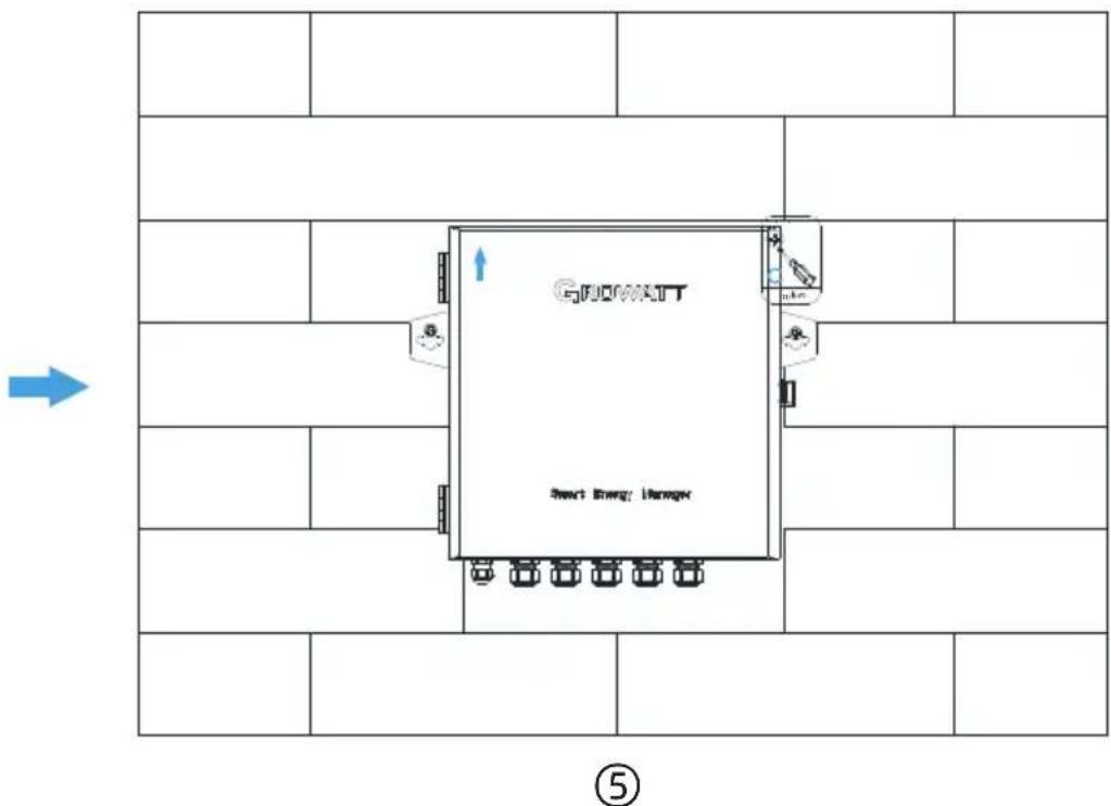
Figure 2-10 Installation and fixing
Note: This product is supplied with a special key to lock the upper cover, which can be operated by the customer according to the actual situation.
2.5 Wiring instructions
Open the upper cover of the communication box of the smart array, and connect according to the figure below. In the absence of an electric meter in the ShineSEM-XA-R, the three current transformers and the voltage sampling interface do not need to be connected.
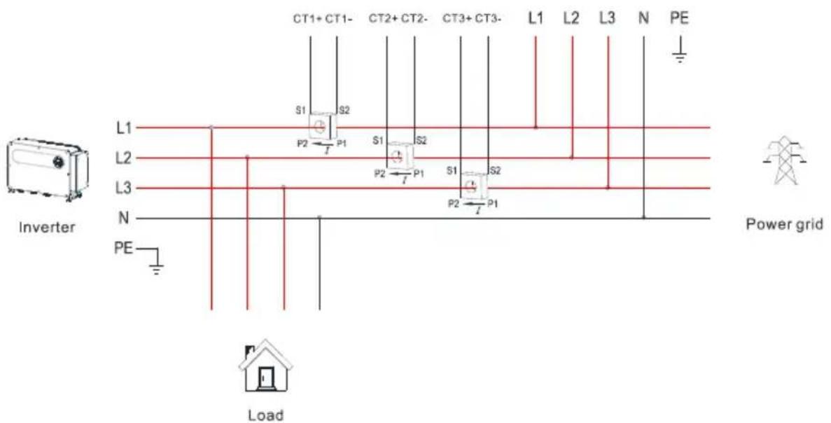
Figure 2-11 Wiring diagram
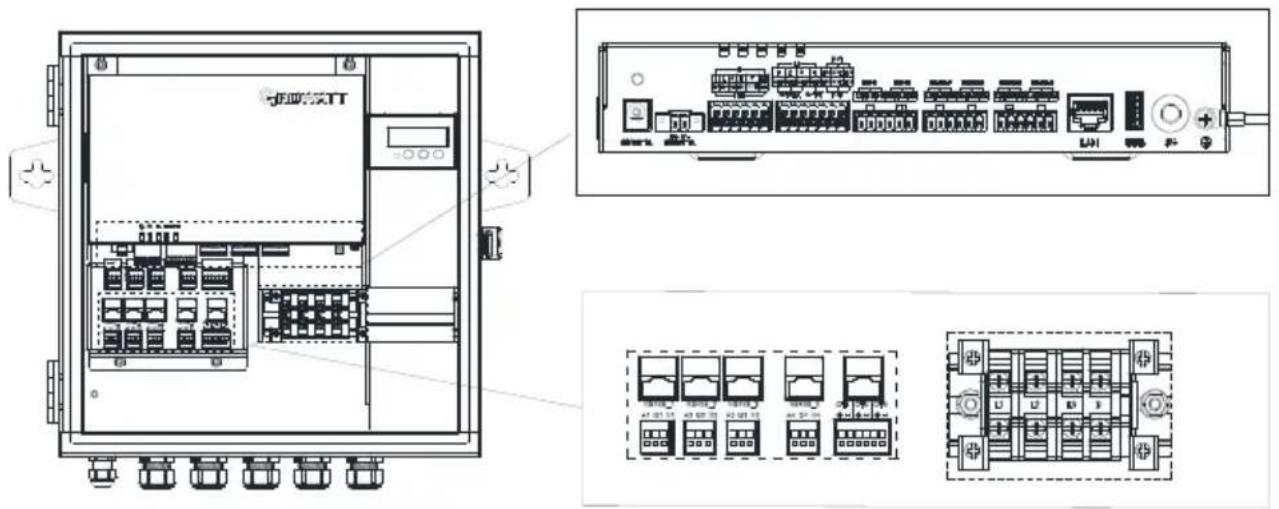
Figure 2-12 Interface terminal diagram
1. Overall wiring
As can be seen from the figure above, the three CTs and AC voltage sampling lines need to be placed between the load and the grid to detect the power of the grid-connected access point in real time. The ShineSEM-XA-R is recommended to be installed near the power distribution cabinet of the grid. The CT and AC voltage sampling lines are placed in the power distribution cabinet.
2. RS485 interface
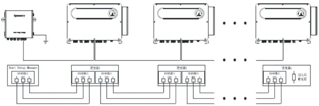
The ShineSEM-XA-R is used to connect the RS485 interface of the inverter. For the wiring method of multiple inverters, please refer to the following figure. The precautions are as follows:
(1) The RS485 wire is recommended to use twisted-pair shielded wire, and the shielding layer is connected to the GND pin of the RS485 interface of the ShineSEM-XA-R and the inverter.
(2) A maximum of 12 inverters can be connected, that is, n≤12. Refer to the wiring diagram and connect them hand in hand.
(3) The collector and the inverter should be connected in a hand-in-hand manner, and the RS 485 interface of the last inverter should be connected to the grounding terminal of the casing to prevent the 485 communication from being interfered.
(4) Power cables, power cables and communication cables must be placed in different trenches to prevent power cables and other cables from running parallel for long distances and reduce electromagnetic interference caused by instantaneous crossover of output voltages. When running RS485 cables and power cables in parallel, the distance should be greater than 0.5 meters.
flowchart
graph TD
    A["Smart Energy Manager"] --> B["Switcher1"]
    A --> C["Switcher2"]
    A --> D["Switcher3"]
    B --> E["RS-18接口"]
    B --> F["RS-20接口"]
    C --> G["RS-18接口"]
    C --> H["RS-20接口"]
    D --> I["RS-18接口"]
    D --> J["RS-20接口"]
    E --> K["RS-18接口"]
    F --> L["RS-20接口"]
    G --> M["RS-18接口"]
    H --> N["RS-20接口"]
    I --> O["RS-18接口"]
    J --> P["RS-20接口"]
    K --> Q["RS-18接口"]
    L --> R["RS-20接口"]
    M --> S["RS-18接口"]
    N --> T["RS-20接口"]
    O --> U["RS-18接口"]
    P --> V["RS-20接口"]
    Q --> W["RS-18接口"]
    R --> X["RS-20接口"]
    S --> Y["RS-18接口"]
    T --> Z["RS-20接口"]
    U --> AA["RS-18接口"]
    V --> AB["RS-20接口"]
    W --> AC["RS-18接口"]
    X --> AD["RS-20接口"]
    Y --> AE["RS-18接口"]
    Z --> AF["RS-20接口"]
    AA --> AG["RS-18接口"]
    AB --> AH["RS-20接口"]
    AC --> AI["RS-18接口"]
    AD --> AJ["RS-20接口"]
    AE --> AK["RS-18接口"]
    AF --> AL["RS-20接口"]
    AG --> AM["RS-18接口"]
    AH --> AN["RS-20接口"]
    AI --> AO["RS-18接口"]
    AJ --> AP["RS-20接口"]
    AK --> AQ["RS-18接口"]
Figure 2-13 RS485 wiring diagram
3. Current transformer interface
There are P1 and P2 silk screens on both sides of the current transformer to distinguish the direction. Refer to Figure 2-5 for wiring. The P1 side is close to the grid, and the P2 side is close to the inverter and load. The transformer connection method is as follows:
(1) S1 of inverter L1 phase current transformer CT1 is connected to CT1's"+', S2 is connected to CT1's"-".
(2) S1 of inverter L2 phase current transformer CT2 is connected to CT2's"+" , S2 is connected to CT2's"-".
(3) S1 of inverter L3 phase current transformer CT3 is connected to CT3's"+" , S2 is connected to CT3's"-".
Precautions:
(1) Before the transformer is installed, its secondary must be connected to the ShineSEM-XA-R to ensure that the secondary of the transformer is not open.
(2) If the on-site primary busbar is a cable, professional electrical personnel can carry out live installation; if the primary busbar is a copper bar, the live operation requires a relatively high level of proficiency for the operator, and insulation protection measures are required.
(3) When installing the transformer, foreign matter such as impurities and dust must not fall into the cutting surface of the iron core, so as not to affect the performance of the transformer.
(4) If the ShineSEM-XA-R is not equipped with an ammeter, no current transformer needs to be installed.
4. Voltage sampling interface
Connect the voltage sampling line as shown in Figure 2-7. According to the three-phase four-wire wiring method, L1/L2/L3/N must be connected, otherwise the ShineSEM-XA-R will not work properly.
5. Network cable interface
Pull a network cable from a router with a network, and plug it directly into the ring network switch of the communication box of the smart subarray. This interface is used for remote monitoring. For details, please refer to Chapter 5.
6. Ground terminal
To ensure the reliable operation and personal safety of the ShineSEM-XA-R, the ground terminal on the housing must be reliably grounded.
Note: Pay attention to the waterproofing of the ground terminal.
2.6 Cable Specifications
| Cable location | Wire cross-sectional area (mm2) | |
| Scope | Recommended value | |
| Rs485 wiring | 1~2.5 (16~14AWG) | 1 (16AWG) |
| Current Transformer Wiring | 1~2.5 (16~14AWG) | 2.5 (14AWG) |
| Voltage Sampling Wiring | 1~2.5 (16~14AWG) | 2.5 (14AWG) |
| Ground wire | 2.5~4 (14~12AWG) | 4 (12AWG) |
Operation and application 3
3.1 ShineMaster4G-X operation introduction
3.1.1 Access ShineMaster4G-X built-in page
You can access the built-in page of ShineMaster - X through static IP or dynamic IP to set or modify parameters of ShineMaster4G-X.
3.1.1.1 Direct connection with computer Access ShineMaster - X built-in page (static IP)
Connect PC and ShineMaster - X directly through network cable. The computer IP is changed to 192.168.0.XXX (XXX ranges from 2 to 253). The default IP of ShineMaster - X is: 192.168.0.254, enter 192.168.0.254 on the computer browser to visit the built-in page of ShineMaster - X. The computer IP setting can refer to the figure below:
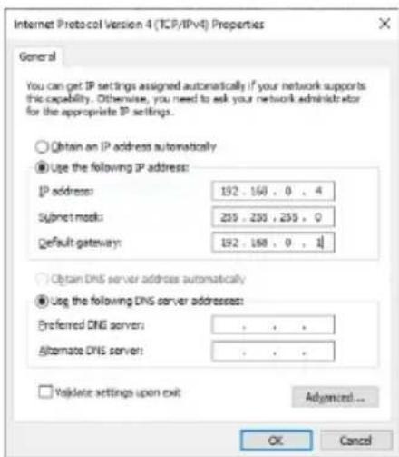
Figure 3-1 Schematic diagram of static IP setting
Note: The address of the DNS server does not need to be set.
3.1.1.2 Access ShineMaster4G-X built-in page through router (dynamic IP)
- Connect the PC and ShineMaster4G-X to the same router so that they are in the same LAN.
Note: The router must enable the DHCP function, and ShineMaster4G-X also needs to enable the DHCP function.
- Check the IP field assigned by the router to the computer.
Enter ipconfig on the command line to view the IP field assigned by the router to the computer
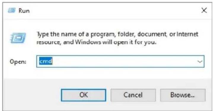
Figure 3-2 Schematic diagram of running window

Figure 3-3 Schematic diagram of command line input
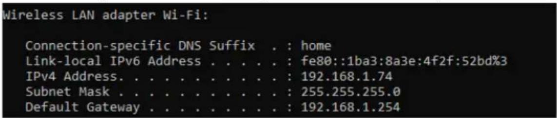
Figure 3-4 Schematic diagram of the results of the ipconfig command
- Enter 192.168.1.254 in the computer browser to access the built-in page of ShineMaster4G-X.

Figure 3-5 Schematic diagram of login IP
3.1.2 Login
- After successfully accessing the built-in page of ShineMaster4G-X, the user needs to log in to modify or set parameters, as shown in the figure below:
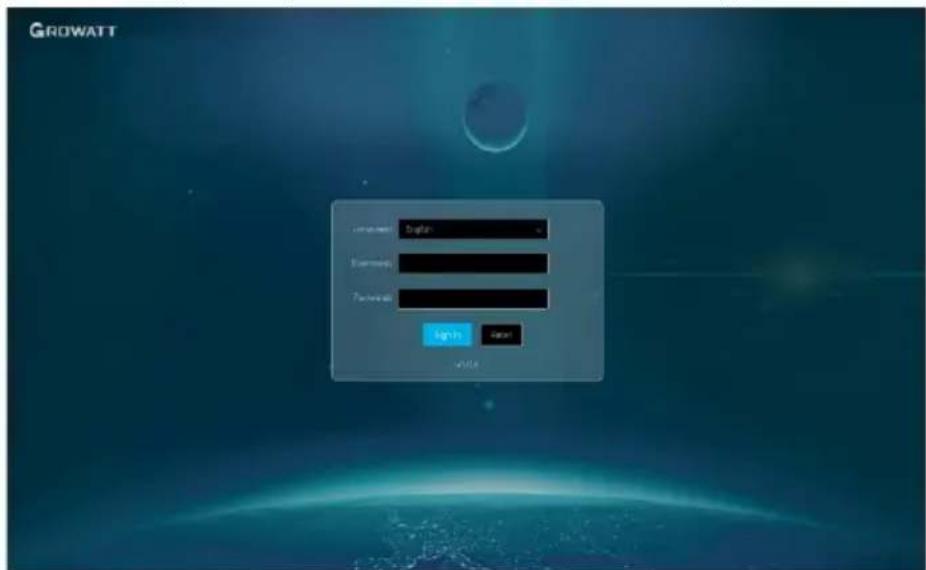
Figure 3-6 Login interface
- Enter the user name and password, the default login user name: admin, password: admin, click login after filling in, enter the ShineMaster4G-X system page.
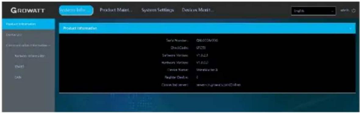
Figure 3-7 System information bar
- The system page mainly includes the following four columns
A. System information, B. Product maintenance, C. System settings, D. Equipment monitoring.
3.1.3 ShineMaster4G-X data collector system information
- Click ShineMaster4G-X system information to view "product information", "device list", "communication information" and other information;
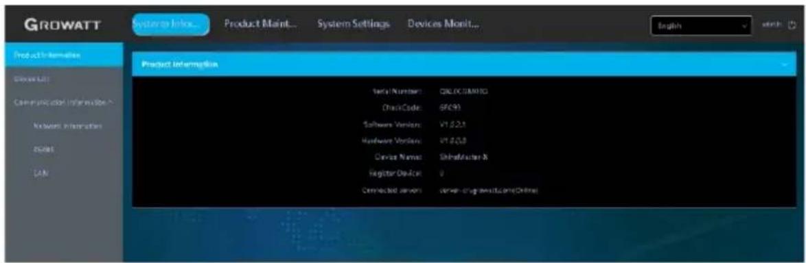
Figure 3-8 System information bar
| Product information | ShineMaster4G-X serial number, software version and other information |
| Device List | Registered device information and online information |
| Internet Information | Details of wired and wireless networks |
| RS485 | Setting information for RS485-1 , RS485-2 , RS485-3 , RS485-4 |
| CAN | CAN communication information |
3.1.4 ShineMaster4G-X collector settings
Log in to the built-in page, the login account is "admin", the password is "admin", select "Device Monitoring" in the first-level menu, select "Inverter" in the second-level menu, and select "Device Maintenance" in the third-level menu.
3.1.4.1 Add monitoring device
(1) Select the device to be added, "inverter", "electric meter", "environmental monitor" and "PID device". Here is an example of adding an inverter:
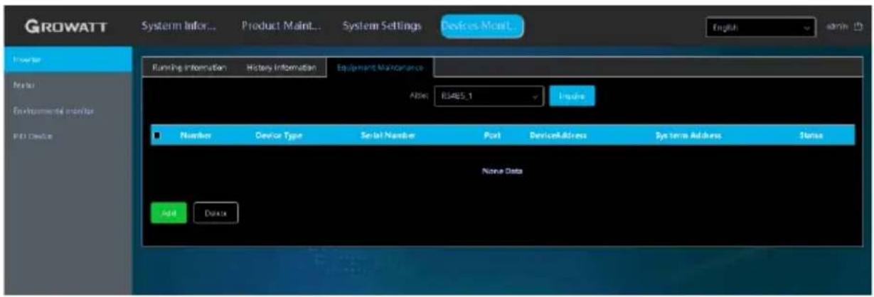
Figure 3-9 Inverter window
(2) Click "Add", and the "Add Data" window will pop up.
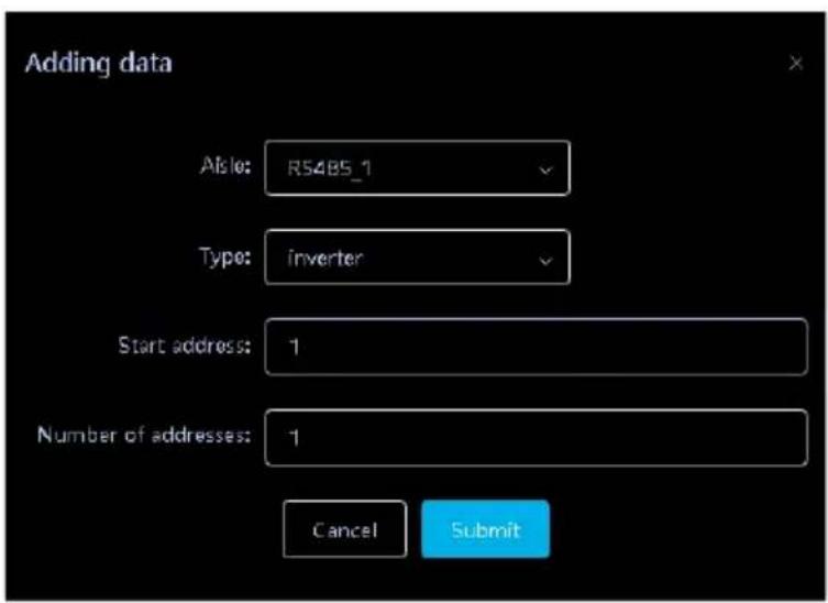
Figure 3-10 Add data window
(3) 485 channel where the device is located in the drop-down list of "Channel", there are four channels of RS 485-1, RS485-2, RS485-3 and RS485-4.
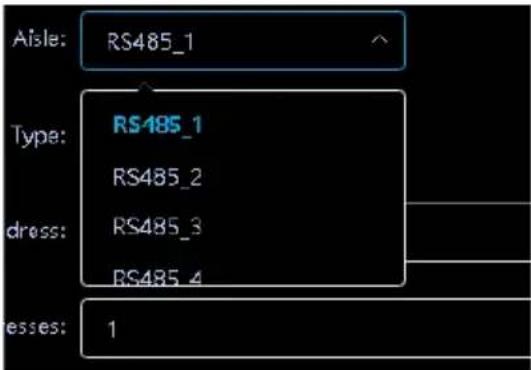
Figure 3-11 Channel selection
(4) Select the device type in the drop-down list of "Type".
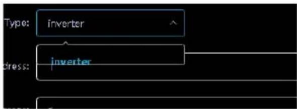
Figure 3-12 Device type selection
(5) "Start address" writes the start address of the added device, for example: suppose the address of the photovoltaic inverter to be monitored is "1", then the start address is 1.
Note: Only 12 devices can be added to each RS 485 channel, and the address of the photovoltaic device is 0-254;

Figure 3-13 Start address filling
(6) Number of addresses: ShineMaster supports adding multiple devices of the same type with consecutive addresses at one time. For example: Suppose there are four photovoltaic inverter addresses to be monitored, and the addresses are 1, 2, 3, and 4 respectively, then write "1" for "start address" and "4" for "number of addresses".
Note: There are only 12 devices that can be added to each RS 485 channel. Assuming that starting from address 1, only 12 devices can be added continuously at a time;

Figure 3- 14 Add the number of addresses
(7) Then click Submit. After the prompt is successful, select "System Information" in the first-level menu, and select "Device List" in the second-level menu to check whether the inverter is added successfully.
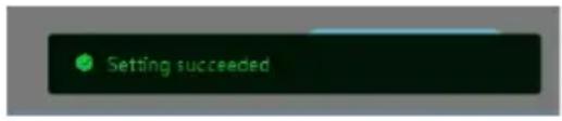
Figure 3-15 Add success prompt
| ☐ | Number | Device Type | Serial Number | Port | DeviceAddress | System Address | Status |
| ☐ | 1 | Inverter | RS485_1 | 1 | 1 | 离线 | |
| ☐ | 2 | Inverter | RS485_1 | 2 | 2 | 离线 | |
| ☐ | 3 | Inverter | RS485_1 | 3 | 3 | 离线 | |
| ☐ | 4 | Inverter | RS485_1 | 4 | 4 | 离线 |
Figure 3-16 Device list
The device types are as follows:
| Inverter | GROWATT Inverter |
| Electric meter | SDM one-way meter |
| SDM three-way electric meter | |
| CHNT one-way meter | |
| CHNT three-way electric meter | |
| Ankerui Meter | |
| GRT meter | |
| Environmental Monitor | Weather station |
| PID device | PID device |
Note: Both SDM120 and SDM230 are one-way meters. If SDM230 is used on site, select SDM120 to add and OK when adding equipment.
3.1.4.2 Delete monitoring device
The deletion of equipment includes "inverter", "electric meter", "environmental monitoring instrument", and "PID equipment". The method of deleting devices is the same, taking the inverter as an example:
(1) Log in to the built-in page, the login account is "admin", the password is "admin", select "Device Monitoring" in the first-level menu, select "Inverter" in the second-level menu, and select "Device Maintenance" in the third-level menu.
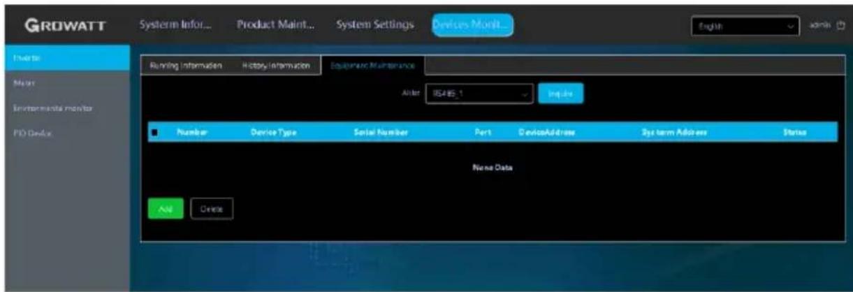
Figure 3-17 Inverter window
(2) Select the RS 485 channel of the photovoltaic inverter in the "Channel" drop-down list, and then click "Query", and the photovoltaic equipment added under the RS 485 channel will be displayed;
| ☐ | Number | Device Type | Serial Number | Port | DeviceAddress | System Address | Status |
| ☐ | 1 | Inverter | RS485_1 | 1 | 1 | 离线 | |
| ☐ | 2 | Inverter | RS485_1 | 2 | 2 | 离线 | |
| ☐ | 3 | Inverter | RS485_1 | 3 | 3 | 离线 | |
| ☐ | 4 | Inverter | RS485_1 | 4 | 4 | 离线 |
Figure 3-18 Device list
(3) Check the photovoltaic equipment that needs to be deleted, click "Delete", and click "Confirm";
| ☐ | Number | Device Type | Serial Number | Port | DeviceAddress | System Address | Status |
| ☒ | 1 | Inverter | RS485_1 | 1 | 1 | 离线 | |
| ☒ | 2 | Inverter | RS485_1 | 2 | 2 | 离线 | |
| ☒ | 3 | Inverter | RS485_1 | 3 | 3 | 离线 | |
| ☒ | 4 | Inverter | RS485_1 | 4 | 4 | 离线 |
Figure 3-19 Schematic diagram of selected devices
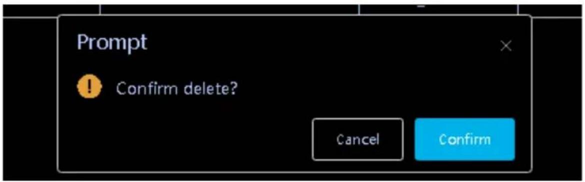
Figure 3-20 Delete prompt
(4) After the prompt is successful, click "Query" again to check whether the deletion is successful;

Figure 3-21 Prompt for successful deletion
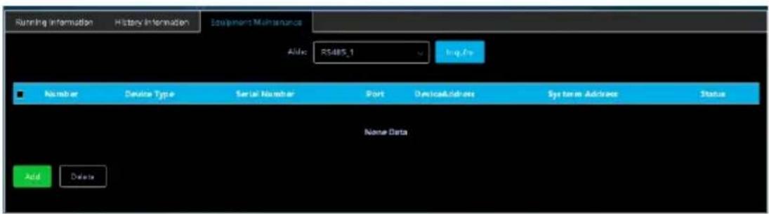
Figure 3-22 Device list
3.1.5 ShineMaster4G-X network settings
When you need to use the remote monitoring function of ShineMaster4G-X, you need to set up its network. Under normal circumstances, the network parameters have been set before leaving the factory, and you can run according to the default configuration.
3.1.5.1 Collector network IP settings
(1) Check whether the ShineMaster4G-X has enabled the DHCP function, log in to the built-in page, the login account is "admin", the password is "admin", and select "Wired Communication" in the left list of "System Settings"
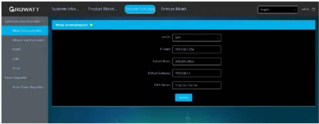
Figure 3-23 Wired communication window
(2) The DHCP function is turned off by default at the factory, and the DHCP function needs to be turned on to automatically obtain an IP address from the router.

Figure 3-24 DHCP enabled
(3) After the setting is successful, it needs to be restarted to take effect.
(4) If you need to set ShineMaster4G-X to a fixed IP during use, you need to perform the following settings: select "Wired Communication" in the left list of "System Settings", and turn off DHCP on the "Wired Communication" interface;
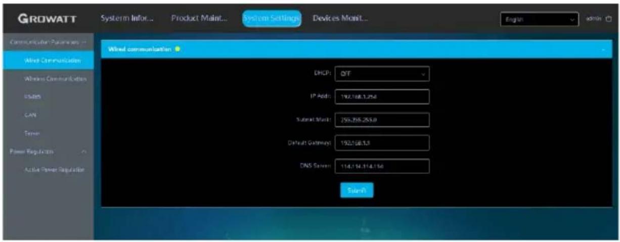
Figure 3-25 Disable DHCP
Enter the user's own IP, gateway, subnet mask, DNS and other parameters, and click "Submit". As shown below
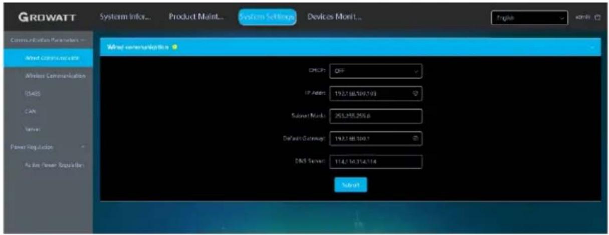
Figure 3-26 Schematic diagram of manual IP configuration
After the setting is successful, a restart is required to take effect.
3.1.5.2 Collector network IP settings
How to set the server address and domain name
(1) Login to the built-in page with the login account as "admin" and password as "admin", select "Server" in the left list of "System Settings", and select "Enable";
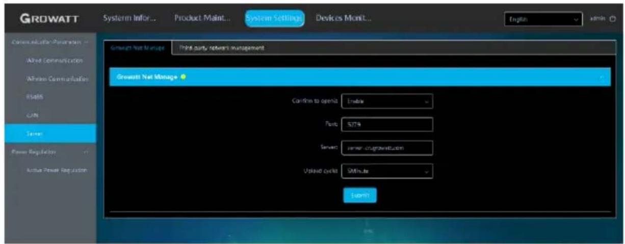
Figure 3-27 Schematic diagram of server settings
(2) Enter the port number of the corresponding server, the domain name of the server, such as server-cn.growatt.com/server.growatt.com , and the time interval for data uploading, click Submit, and it will prompt to refresh the interface successfully to check whether the modification is successful.
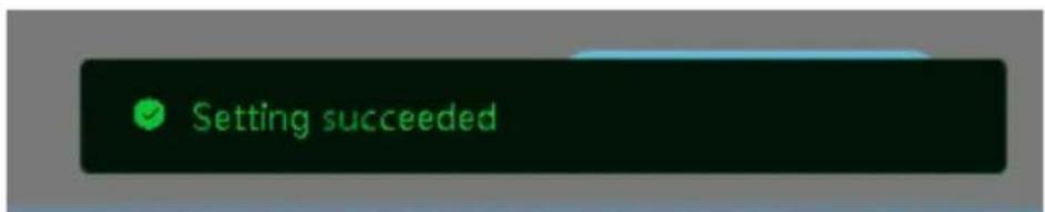
Figure 3-28 Prompt for successful server setup
(3) After the setting is successful, it needs to be restarted to take effect.
3.1.6 Power adjustment settings
3.1.6.1 Enable active power adjustment
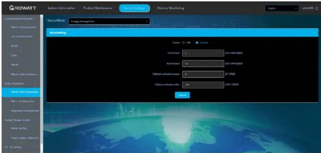
Figure 3-29 Enable active power adjustment
- Power drawn from the grid: the maximum power allowed to be drawn from the grid (load consumption + battery charging power).
- Feed-in power: the power allowed to be fed to the grid (only the PV power can be exported to the grid, not the battery power)
- Fail-safe protection power limit: the power (%) of the PV inverter or storage inverter in case that the power adjustment fails
- Failure time: time limit within which the communication between the PV inverter, storage inverter and datalogger is disconnected. If the datalogger constantly fails to communication with the PV inverter and storage inverter within this duration, the PV inverter and storage inverter will enter the Failure State.
Note:
- The residential storage inverter carries out load compensation during power adjustment. Whenever the load is consuming power, the datalogger will adjust the storage inverter and the PV inverter to perform load compensation, which is not affected by the pre-set value of power drawn from the grid.
- The WIS Commercial and Industrial Storage Inverter mainly compensates the grid power. It carries out grid compensation when the power imported from the grid exceeds the pre-set value.
- Two types of Failure State:
(1) If the communication between the datalogger and the export limitation meter is abnormal, the datalogger will set the PV inverter and storage inverter into the Failure State and operate at the failure power level. This status can only be cleared by the datalogger.
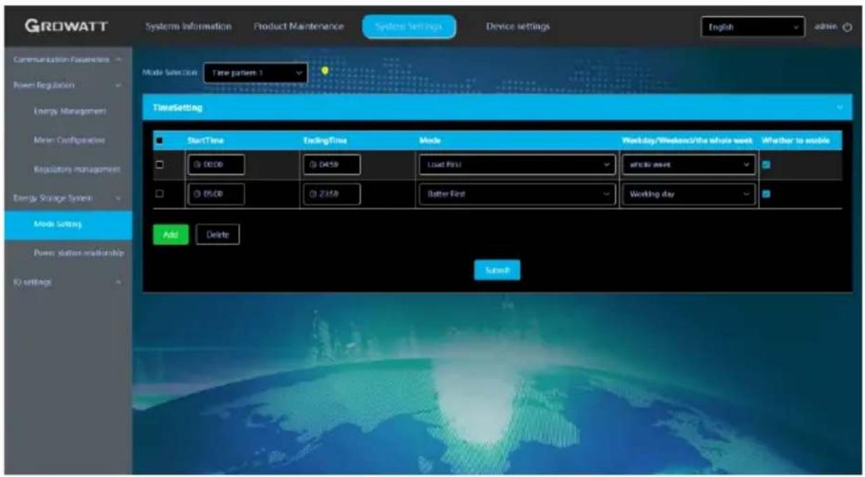
Figure 3- 32 Time mode settings
Multiple time mode settings. You can select Special Day 1, Special Day 2, Quarter (1, 2, 3 4) or Full year, as shown below:
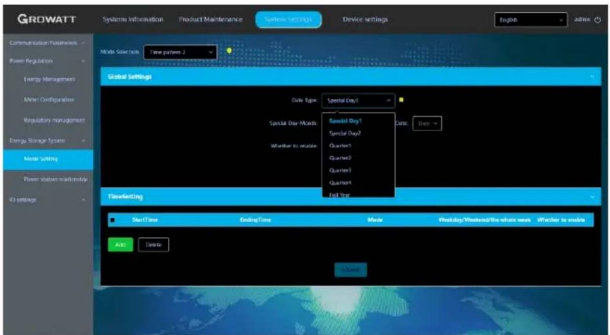
Figure 3- 33 Time mode settings
Procedure to set the working mode for idle time is illustrate below:
(1) Add a time segment. When the cursor is on the Start Time (00:00) filed, the "x" icon will be displayed, as the following figure shows.
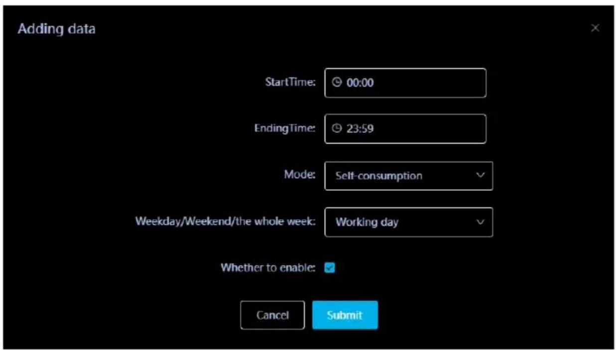
Figure 3- 34 Idle time settings
(2) Click the "x" icon, then you can set the working mode for idle time based on the inverter model and on-site situations.
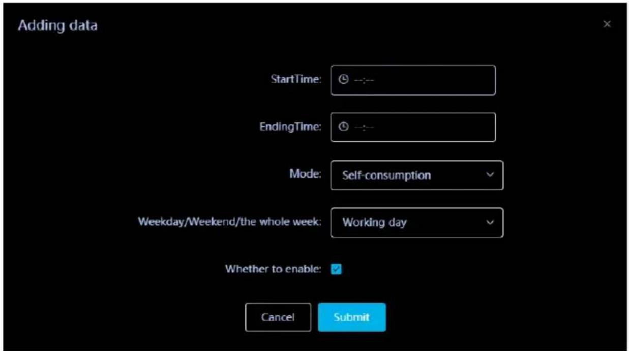
Figure 3-35 Idle time settings
(2) If the datalogger fails to communicate with the PV inverter and PCS over the failure time, the PV inverter and storage inverter will enter the Failure State and operate at the failure power level. When the communication is re-connected, the PV inverter and storage inverter will exit the Failure State.
3.1.6.2 Meter configuration
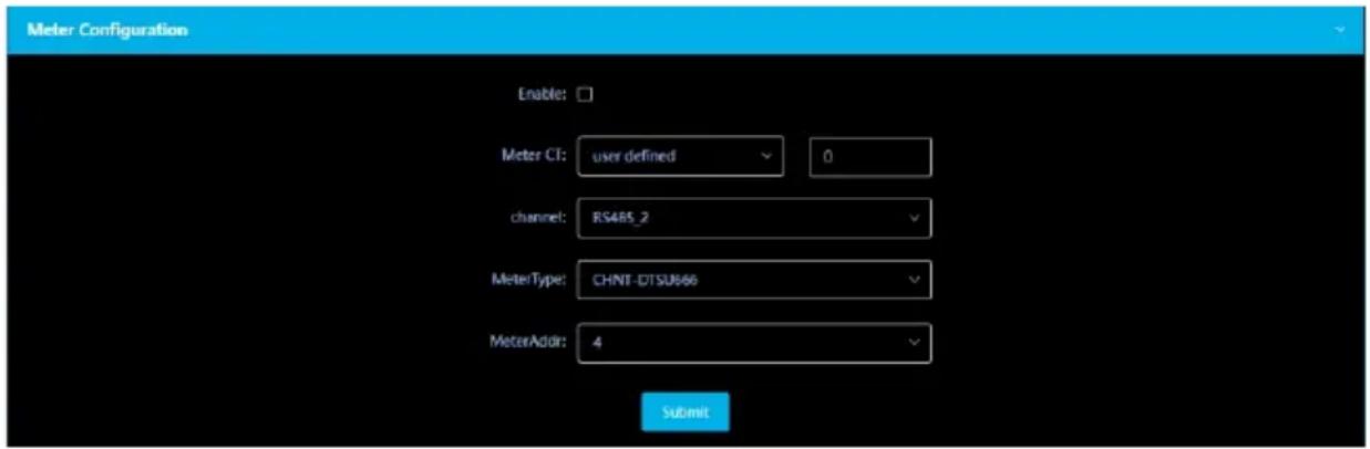
Figure 3-30 Meter configuration
- When the power meter is enabled for power adjustment, the power value of the meter will be read every 100ms.
- Meter CT: Select the CT configuration of corresponding specifications based on on-site situations (the CT ratio can be customized). If the ShineMaster4G-X is integrated in the SEM-X, the CT has been configured before delivery, therefore configuration of the CT is not required and the default value is "No". This is only for the export limitation meter.
- Port: The default value is RS485-2 for the export limitation meter. You can select the RS485 route based on the actual wiring situation.
- Meter type and address: Select the corresponding value based on the actual wiring situation. The default address value is 2 for the Eastron three-phase meter; 4 for the CHINT three-phase meter.
3.1.6.3 Adjustment management

Figure 3-31 Adjustment management
This setting item is to set the power adjustment mode:
- Total Phase Adjustment: read Phase A, B and C power of the meter or the total power. Adjust the power of the PV inverter or storage inverter based on the total-phase power and direction.
- Minimum Phase Adjustment: read Phase A, B and C power of the meter. Adjust the power of the PV inverter or storage inverter based on the minimum phase power and direction.
- Single Phase Adjustment: read Phase A, B and C power of the meter. Adjust the power of the PV inverter or storage inverter based on the power and direction of each phase.
Note:
(1) If set to "Disable", the adjustment mode is "Total Phase Adjustment" by default.
(2) If all inverters installed on site are PV inverters, you cannot select Single Phase Adjustment. The Single Phase Adjustment function is not available for PV inverters and you can only select Total Phase Adjustment or Minimum Phase Adjustment.
3.1.6.4 Time mode settings
Time mode settings is about defining the working mode of the storage inverter during different time segments. The main working modes are described below:
- Load First: prioritizes supplying power to the loads. Both PV power and battery power can be used for supporting the loads. When importing power from the grid to power the loads, the storage inerter will output corresponding power for compensation. When exporting power to the grid, it should not exceed the Feed-in Power.
- Battery First: prioritizes supplying power to the loads. Both PV power and battery power can be used for supporting the loads. When the load power is less than the permitted power drawn from the grid, it will adjust to charge the battery. Charging power range: load power + battery charging power < permitted power drawn from the grid. In case that the power drawn from the grid exceeds the permitted value, it will reduce the battery charging power. If there is any surplus PV power, it can be fed to the grid, which should not exceed the pre-set feed-in power.
- Grid First: prioritizes supplying power to the loads. Both PV power and battery power can be used for supporting the loads. The surplus power will be fed to the grid, which should not exceed the pre-set feed-in power.
- PV-only storage: prioritizes supplying power to the loads and the battery is not allowed to discharge. The PV power can charge the battery, but the grid power cannot charge the battery. The excess PV power can be fed to the grid. Both PV power and the AC grid power can be used to supply power to the loads. In the off-grid mode, the battery will discharge to power the loads. If the battery energy is not available and an SYN (ATS) is installed, the generator can supply power to the loads.
- Battery Idle Mode: the battery does not charge or discharge power. The PV power is used to support the loads, and the surplus PV power can be fed to the grid. It is allowed to draw power from the grid to power the loads. For backup power during power outage, in the off-grid mode, the PV power and battery power are used to power the loads.
- Standby Mode: the storage inverter does not charge or discharge the battery. Configure the 9 time windows. Select the appropriate working mode for each time segment based on actual demands.
Note:
- During idle time, the working mode is set to Standby Mode by default if not configured. Idle time: all time that has not been configured.
- Overlapping time segments are not allowed. For instance, if Quarter 1 is selected and the first time segment is set to 8:00 am - 10:00 am, then setting the second time window to 9:00 am - 11:00 am would be invalid. For different time modes, the time segment can be set to the same value. For instance, if one segment is set to 8:00 am - 10:00 am for Special Day 1, setting the time window to 8:00 am - 10:00 am for Special Day 2 would be valid.
- Priority: Special Day 1 > Special Day 2 > Quarter (1 > 2 > 3 > 4) > Full year.
3.1.7 Third-party server configuration
3.1.7.1 Third-party server configuration over MODBUS TCP
Note:
- It is disabled by default.
- Three options are available: Disable; Enable (limited); Enable (unlimited).
- Disable: Disable connection over MODBUS TCP, prohibiting the third-party management system from connecting to the ShineMaster4G-X
- Enable (limited): Only the pre-configured client IP addresses are allowed to be connected to the ShineMaster4G-X server. Less than 3 client IP addresses can be connected and they are configurable.
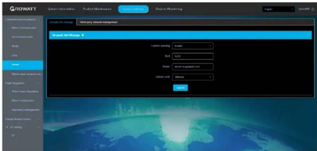
Figure 3- 36 MODBUS TCP settings
3.1.7.2 Third-party server configuration over IEC104
Note:
- It is disabled by default.
- Three options are available: Disable; Enable (limited); Enable (unlimited).
- Disable: Disable connection over IEC104, prohibiting the third-party management system from connecting to the ShineMaster4G-X server.
- Enable (limited): Only the pre-configured client IP addresses are allowed to connect to the ShineMaster4G-X server. Less than 3 client IP addresses can be connected and they are configurable.
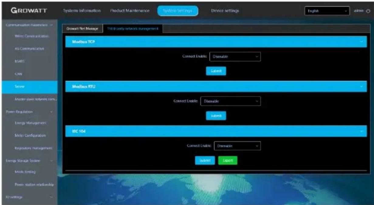
Figure 3-37 IEC104 settings
3.1.8 Power plant relationship configuration
Note: All meters involved in the power plant relationship should be on the same node.
- Configure the relationship according to the relations of the meters connected to the power plant.
- After the configuration is complete, click "Submit" to save your settings.
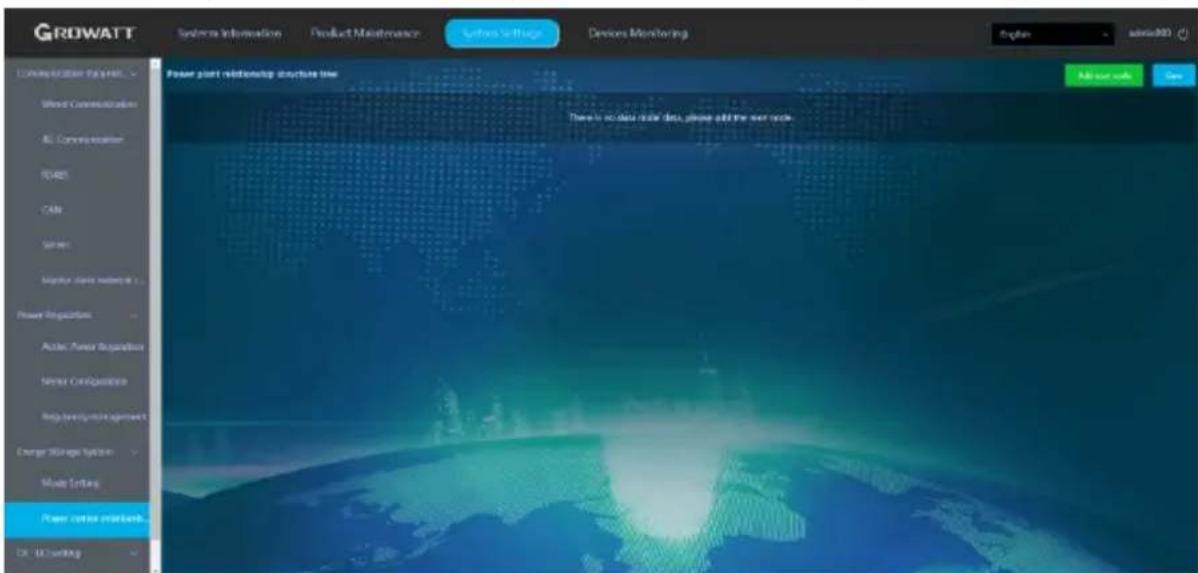
Figure 3-38 Plant relationship settings
![Add Node Node type: Meter MeterType: Load side meter Meters to be added: QXL0D00002(system_addr: 2) Sys term Address: 2 Device related data: channel: RS485_2[1] Type: SDM630MCT[67] Address: 2 Cancel Submit](/content/2026/05/854848/images/985dd14acbc47eac776b7c3f41aed1c8a48004093b006f7e20c5f699eceee131.jpg)
Figure 3-39 Adding nodes
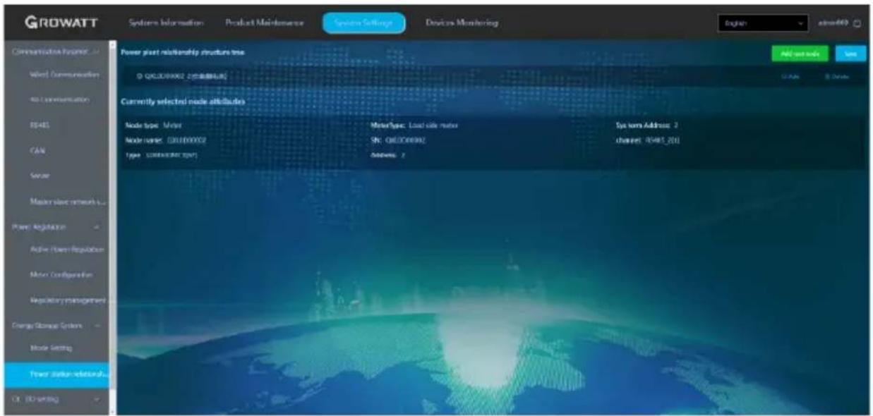
Figure 3-40 Power plant relationship Show
3.1.9 Precautions for operation on the configuration page
- If the interface is not refreshed for a long time after clicking Save when adding a device, power off and restart the collector. After restarting, click "Device Status" to check whether the last operation was successful.
- When configuring the parameters of the corresponding functions, only the parameters of the corresponding function should be configured as described above, other parameters not related to the desired configuration function remain unchanged.
Specification parameters and 4 model description
4.1 Specification parameters
| ShineSEM-XA-R (with electric meter) | |||||
| Technical Parameters | |||||
| Input voltage parameter | |||||
| Rated input voltage/range(three specifications) | 400Vac | ||||
| Rated input frequency/range | 50/60Hz | ||||
| Grid connection type | 3W/N/PE | ||||
| Input current and CT parameters | |||||
| Maximum detection current(CT primary side current) | 250A | 600A | 1200A | 2000A | 4000A |
| Input current(CT secondary side current) | 5A | ||||
| Current Detection Accuracy (CT) | 0.5 | 0.2 | |||
| Communication Interface | |||||
| RS485 | Have | ||||
| Ethernet | Have | ||||
| Maximum number of inverterconnections | 48PCS | ||||
| Maximum communicationdistance | Rs485 standard twisted pairshielded wire: 500mEthernet cable: 50m | ||||
| General parameters | |||||
| Dimensions(height*width*thickness) | 352*430*109mm | ||||
| Weight | 8.7kg | ||||
| Range of working temperature | -30°C - +60°C | ||||
| Degree of protection | IP66 | ||||
| Relative humidity | 5%-95%, no condensation | ||||
| Placement | Indoor | ||||
| Maximum working altitude | 4000m | ||||
| Terminal type | U-shaped terminal | ||||
| Standards met | |||||
| Safety | CE、Rohs | ||||
| Note: | 1. The total power of inverters or loads in theentire system cannot exceed thecorresponding system capacity of theShineSEM-XA-R. | ||||
4.2 Model description
ShineSEM-XA-R
①
②③
④⑤
The model introduction of the ShineSEM-XA-R takes ShineSEM-XA-RA-RL EU as an example:
| logo | meaning | Value |
| 1ShineSEM | Product Identification | ShineSEM: Communication Box |
| 2XX | Model representative | X: 1st generation, X2: 2nd generation, in descending order |
| 3A | Derived models | A、B、C |
| 4R | Functional ID | R: anti-reflux boxC: communication box |
| 5Void | Voltage level | L: 380V/4000V |
Intelligent sub-array communication box, configuration barcode introduction:
| optional features | SPF: with ring network communication functionLTE: with 4G communication functionEXT: With extended version, add 4 channels of 485 channels |
| Meter lines | 3P4: The electric meter connection line adopts the three-wire four-phase system3p3: The connection line of the electric meter adopts the three-wire three-phase system2P3: The electric meter connection line adopts the split-phase connection method1P2: The electric meter connection line adopts single-phase connection method |
| Current CT ratio | 250/5A, 600/5A, 1200/5A, 2000/5A, 4000/5A, 6000/5A |
| Power (the current anti-reflux system supports a maximum capacity of 100KW) | 100KW, 300KW, 600KW, 1MW, 2MW, 3MW |
Contact us 5
Growatt New Energy provides customers with comprehensive technical support. Users can contact the nearest Growatt New Energy office or customer service point, or directly contact the company's customer service center.
Shenzhen Growatt New Energy Co., Ltd.
4-13/F, Building A, Sino-German (Europe) Industrial Park, Hangcheng Blvd, Bao'an District, Shenzhen, China
T +86 755 2747 1942
E service@ginverter.com
W www.ginverter.com

natural_image
Stylized globe with leafy tree and globe, symbolizing global nature (no text or symbols)
Download
Manual





Growatt New Energy
Shenzhen Growatt New Energy Co., Ltd.
4-13/F, Building A, Sino-German (Europe) Industrial Park, Hangcheng Blvd, Bao'an District, Shenzhen, China
T +86 755 2747 1942
E service@ginverter.com
W www.ginverter.com
GR-UM-433-A-00 (PN:044.0134000)


- CONTENT
- About this manual ....1
- Product introduction and installation .... 2
- Operation and application.... 12
- Specification parameters and model description 30
- contact us.... 32
- About this manual
- Manual description
- Copyright notice
- Applicable personnel
- Manual usage
- introduction and installation 2
- Product
- Product appearance and internal structure
- Appearance
- Internal structure
- ShineMaster status LED light
- Air isolating switch
- Wiring terminal block
- Electric surface panel
- Current transformer
- Note:
- Introduction to working principle
- Unpacking
- Installation
- Wiring instructions
- Overall wiring
- RS485 interface
- Current transformer interface
- Precautions:
- Voltage sampling interface
- Network cable interface
- Ground terminal
- Operation and application 3
- ShineMaster4G-X operation introduction
- Access ShineMaster4G-X built-in page
- Direct connection with computer Access ShineMaster - X built-in page (static IP)
- Access ShineMaster4G-X built-in page through router (dynamic IP)
- Login
- ShineMaster4G-X data collector system information
- ShineMaster4G-X collector settings
- Add monitoring device
- Delete monitoring device
- ShineMaster4G-X network settings
- Collector network IP settings
- Collector network IP settings
- Power adjustment settings
- Enable active power adjustment
- Meter configuration
- Adjustment management
- Time mode settings
- Third-party server configuration
- Third-party server configuration over MODBUS TCP
- Third-party server configuration over IEC104
- Power plant relationship configuration
- Precautions for operation on the configuration page
- Specification parameters and 4 model description
- Model description
- ShineSEM-XA-R
- Contact us 5
- Shenzhen Growatt New Energy Co., Ltd.
Brand : Growatt
Model : SEM-X
Category : Uncategorized