
TPM-CT-E-EU - Uncategorized Growatt - Free user manual and instructions
Find the device manual for free TPM-CT-E-EU Growatt in PDF.


| Product Type | Three-phase DIN rail energy meter (SDM630MCT V2) |
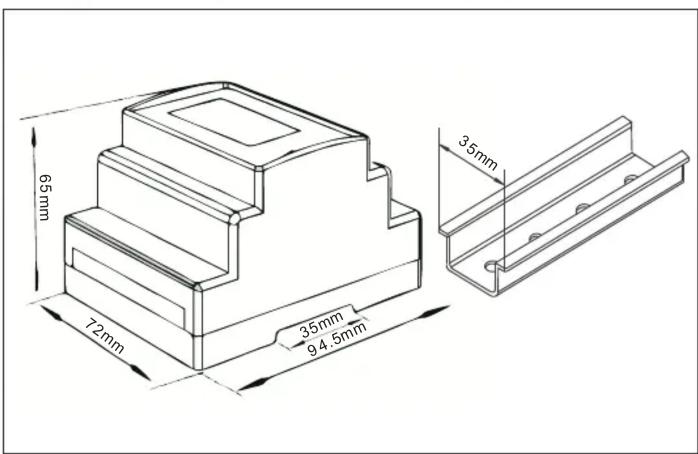
| Dimensions (L x W x H) | 94.5 x 72 x 65 mm |
| Weight | Approximately 0.3 kg |
| Rated Voltage | 3 x 230/400 VAC (L-N/L-L) |
| Frequency | 50/60 Hz |
| Auxiliary Power Supply | 85-275 VAC or 120-380 VDC |
| Input Current Range | 1A or 5A (via external CT) |
| Accuracy (Active/Reactive Power) | 0.5% of range maximum |
| Communication Interface | RS485 Modbus RTU (max 38400 bps, default 9600) |
| Measured Parameters | Voltage, current, power, energy, frequency, harmonics, power factor, demand |
| Display Type | Touch-sensitive buttons (ESC, UP, DOWN, ENTER) |
| Protection Level | IP51 (indoor) |
| Installation Category | CAT III |
| Mounting | DIN rail 35 mm |
| Included Accessories | 3x current transformers (CT), 15m RS485 cable, quick guide |
| CT Ratios Supported | 250/5A, 600/5A, 1200/5A |
| Operating Temperature | -25°C to +55°C (regulated), -40°C to +70°C (limited) |
| Humidity | ≤90% annual average |
| Maintenance | Keep dry, clean with dry cloth; disconnect power before cleaning |
| Safety | Disconnect all power before installation; secure wiring; use proper CT orientation |
| Spare Parts Availability | CTs, RS485 cable (up to 100m), connectors |
| Reparability | Contact local supplier; no user-serviceable parts inside |
Frequently Asked Questions - TPM-CT-E-EU Growatt
User questions about TPM-CT-E-EU Growatt
0 question about this device. Answer the ones you know or ask your own.
Ask a new question about this device
Download the instructions for your Uncategorized in PDF format for free! Find your manual TPM-CT-E-EU - Growatt and take your electronic device back in hand. On this page are published all the documents necessary for the use of your device. TPM-CT-E-EU by Growatt.
USER MANUAL TPM-CT-E-EU Growatt
SDM630MCT V2 is a multi-functional din-rail meter designed for accurate measurement and display of parameters in 3P3W/3P4W power grid systems, such as voltage, current, power, frequency, active power, reactive power, positive energy, reverse energy, total harmonics, etc. It is an ideal choice for real-time power monitoring, featuring a wide range of functions and applications with high stability over extended service life. The meter works with an external current transformer and can be applied in both high and low voltage power grid. It comes with an RS485 communication interface, which supports a maximum baud rate of 38400 bps and enables remote communication.
- Technical Parameters
| General Specifications | |
| Rated voltage | 3×230/400Vac |
| Rated frequency | 50/60Hz |
| L-N voltage range | 100 ~ 276Vac |
| L-L voltage range | 173 ~ 480Vac |
| Auxiliary power voltage range | 85 ~ 275Vac or 120 ~ 380Vdc |
| AC withstand voltage | 4KV for 1min |
| Input current range | 1A or 5A |
| Short-term overcurrent | 20*IMAX for 0.5s |
| Max. Reading | 9999999.9kWh/kVArh |
| Accuracy | |
| Active power | 0.5% of range maximum |
| Reactive power | 0.5% of range maximum |
| Environment | |
| Regulated working temperature range | -25°C~+55°C |
| Limited working temperature range | -40°C~+70°C |
| Relative humidity annual average | ≤90% |
| Installation category | CAT III |
| Degree of pollution | RoHS compliant |
| Communication | |
| Communication | RS485 output for Modbus RTU |
| Baud rate | 9600bps(default) |
| Pulse | 3200imp/kWh |
| Mechanics | |
| Outline dimensions | 94.5x72x65mm(LxWxH ) |
| Din rail dimensions | DIN rail 35mm |
| Protection level | IP51 (indoor) |
- Unpacking
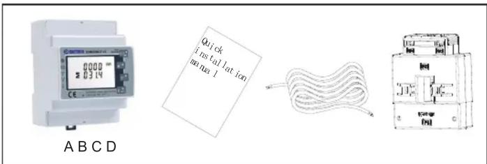
| Item | Quantity | Description |
| A | 1 | Three-phase meter |
| B | 1 | Quick Installation Guide |
| C | 1 | RS485 cable (standard length: 15m) |
| D | 3 | Current Transformer |
- Dimensions (Unit: mm)
5. Installation
Note:
- The Growatt Storage Inverter and the Hybrid Inverter are hereinafter referred to as "the Storage/Hybrid Inverter".
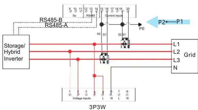
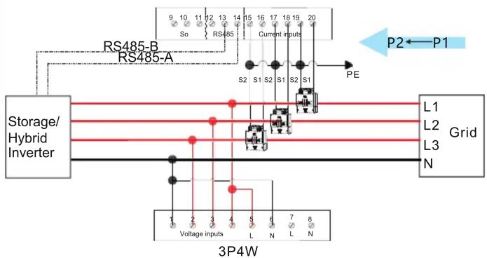
- The grid is on the right side and the current flows from P1 to P2 (from the grid to the load).
- The Growatt Storage Inverter and the Hybrid Inverter are hereinafter referred to as "the Storage/Hybrid Inverter".
- The grid is on the right side and the current flows from P1 to P2 (from the grid to the load).
flowchart
graph TD
    A["Storage/Hybrid Inverter"] -->|RS485-A| B["RS485-B"]
    B --> C["Current inputs"]
    C --> D["PE"]
    D --> E["P2"]
    E --> F["P1"]
    G["Grid"] --> H["L1"]
    G --> I["L2"]
    G --> J["L3"]
    G --> K["N"]
    L["Voltage inputs"] --> M["3P3W"]
    N["L"] --> O["6"]
    P["N"] --> Q["7"]
    R["1"] --> S["2"]
    T["2"] --> U["3"]
    V["4"] --> W["5"]
    X["6"] --> Y["7"]
    Z["8"] --> AA["9"]
flowchart
graph TD
    A["Storage/Hybrid Inverter"] -->|RS485-B| B["Current Inputs"]
    A -->|RS485-A| C["Current Inputs"]
    B --> D["PE"]
    C --> D
    D --> E["L1 Grid"]
    D --> F["L2 Grid"]
    D --> G["L3 Grid"]
    H["Voltage inputs"] --> I["3P4W"]
    J["N"] --> I
    K["S1 S2 S3"] --> I
    style A fill:#f9f,stroke:#333
    style B fill:#ccf,stroke:#333
    style C fill:#ccf,stroke:#333
    style D fill:#cfc,stroke:#333
    style E fill:#fcc,stroke:#333
    style F fill:#fcc,stroke:#333
    style G fill:#fcc,stroke:#333
    style H fill:#fff,stroke:#333
    style I fill:#fff,stroke:#333
| A. Voltage sampling and power supply wiring3P3W: Wiring of the L1 voltage sampling line: corresponding to meter Pin 4 Wiring of the L2 voltage sampling line: corresponding to meter Pin 1 Wiring of the L3 voltage sampling line: corresponding to meter Pin 2 | 3P4W: Wiring of the L1 voltage sampling line: corresponding to meter Pin 4 Wiring of the L2 voltage sampling line: corresponding to meter Pin 3 Wiring of the L3 voltage sampling line: corresponding to meter Pin 2 Wiring of the N voltage sampling line: corresponding to meter Pin 1 |
| B. Current transformer wiringPlease refer to the diagram above. The grid is on the right and the current flows from K to T (from the grid to the load). Wiring of the L1 CT: S1 Line corresponding to meter Pin 16, S2 Line corresponding to meter Pin 15 Wiring of the L3 CT: S1 Line corresponding to meter Pin 20, S2 Line corresponding to meter Pin 19 | Wiring of the L1 CT: S1 Line corresponding to meter Pin 16, S2 Line corresponding to meter Pin 15 Wiring of the L2 CT: S1 Line corresponding to meter Pin 18, S2 Line corresponding to meter Pin 17 Wiring of the L3 CT: S1 Line corresponding to meter Pin 20, S2 Line corresponding to meter Pin 19 |
| C.RS485 cable wiringConnect the RS485A to Pin 14 and RS485B to Pin 13 (The network cables delivered with the inverter are labeled as 485-A and 485-B; if you are using the cables purchased yourself, make sure to differentiate between 485-A and 485-B.) | |
D. Connecting the meter to the Growatt Three-phaseStorage/Hybrid Inverter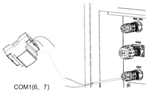 | E. When connecting the smart meter to the inverter, connect one end of the cable to Terminal 13 (485B) and Terminal 14 (485A) of the smart meter and the other end to Pin 6 (485A) and Pin 7 (485B) of the COM1 port.Note: In most cases, the red cable is used for 485A and the black cable for 485B.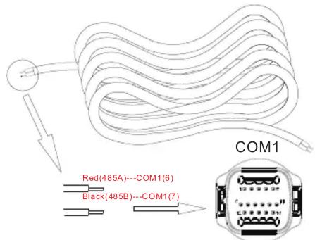 |
F. Dismantle the 16-pin connector delivered with the inverter and set aside the water-proof plug. Route the cables through each part sequentially, then connect them to Pin 6 and Pin 7. Finally, connect the connector to the COM1 port of the inverter.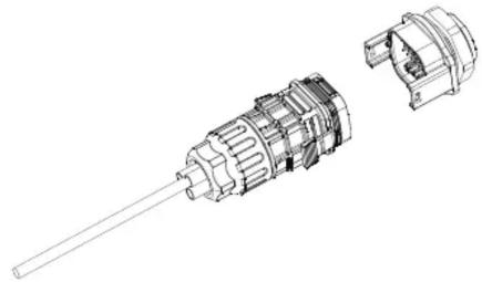 | G. The standard RS485 cable length is 15m. If a longer RS485 cable is required, please use an intact cable and make sure the RS485 cable is less than 100m (the recommended length is less than 25m).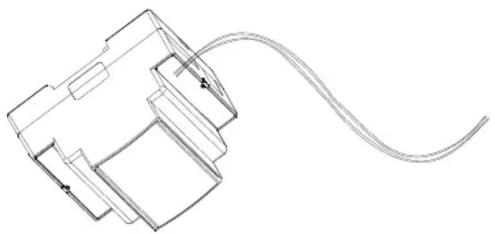 |
6. Button Description and Display
There are four touch buttons on the panel, arranged from top to bottom as follows: “ESC(←)V/A”, “↑(Alt)MD/PH/HZ”, “↓(Shift)P”, “ENTER(→)E”. These buttons can be operated in two ways: long press (pressing for more than two seconds) and short press (pressing for less than one second).
| NO. | Button | Features | Viewable content(short press) | |
| 1 |  | Short press:display voltage and current, ←Long press: ESC | Phase voltage, Line voltage, Phase current, Neutral current, Voltage harmonics, Current harmonics | |
| 2 |  | Short press: display power factor and frequency, ↑Long press: Alt | Phase(Total) frequency, Total power factor, Phase(Total) maximum current demand | |
| 3 |  | Short press: display power, ↓Long press: Shift | Phase(Total) active power, Phase(Total) reactive power, Phase(Total) apparent power | |
| 4 |  | Short press:display electric energy, →Long press: Enter | Total active electric energy, Total reactive electric energy, Positive active electric energy, Reverse active electric energy, Positive reactive electric energy, Reverse reactive electric energy | |
The default communication address for the meter and the Growatt Three-phase Storage/Hybrid Inverter is 02, the default baud rate is 9600 and the current ratios are 250A/5A, 600A/5A, 1200A/5A, which are determined by the CT that is connected. If the communication between the meter and the inverter is not established, please check if the communication address and the baud rate are correctly set.
Long press E ▶ to access the settings menu (the password is 1000 by default, then use M ▲ and P ▼ to navigate to the desired page. If the page flashes, it indicates that you can configure the parameter using the M ▲ and P ▼ buttons; if not, press E ▶ to
enter the selection routine. Then long press

onfirm your setting and press


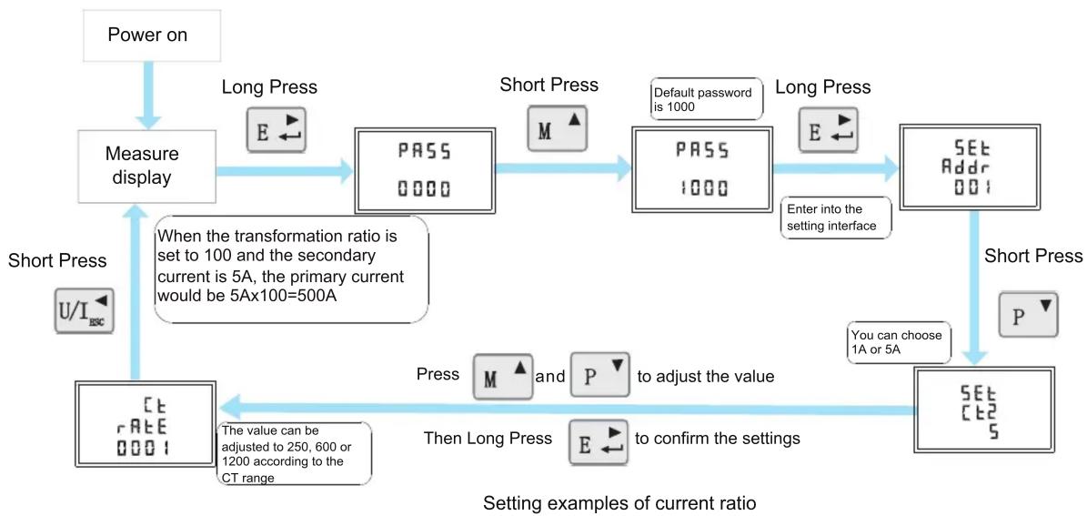
flowchart
graph TD
    A["Power on"] --> B["Measure display"]
    B --> C{Long Press}
    C --> D["PASS 0000"]
    D --> E{Short Press}
    E --> F{PASS 1000}
    F --> G["SET Addr 001"]
    G --> H{Short Press}
    H --> I["SET CT2 S"]
    I --> J{To adjust the value}
    J --> K["Press M and P to confirm the settings"]
    K --> L["Then Long Press"]
    L --> M["The value can be adjusted to 250, 600 or 1200 according to the CT range"]
    M --> N["When the transformation ratio is set to 100 and the secondary current is 5A, the primary current would be 5Ax100=500A"]
    N --> O["Short Press U/I ISC"]
Note: The meter can be connected to the Growatt Three-phase Storage/Hybrid Inverter in two ways and can be set as 3P3W or 3P4W before operating.
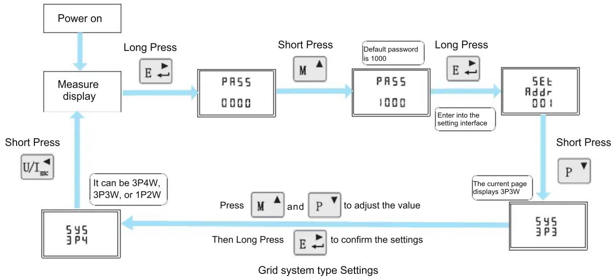
flowchart
graph TD
    A["Power on"] --> B["Measure display"]
    B --> C["Long Press"]
    C --> D["PASS 0000"]
    D --> E["Short Press"]
    E --> F["PASS 1000"]
    F --> G["Default password is 1000"]
    G --> H["SET Addr 001"]
    H --> I["Short Press"]
    I --> J["The current page displays 3P3W"]
    J --> K["Press M and P to adjust the value"]
    K --> L["Then Long Press to confirm the settings"]
    L --> M["It can be 3P4W, 3P3W, or 1P2W"]
    M --> N["Short Press U/I SSC"]
    N --> B
- Troubleshooting
| Fault phenomenon | Reason analysis | Solution |
| Metering inaccuracy | 1. Wiring error, check whether the corresponding phase sequence of voltage and current is correct.2. Check if the output line of the current transformer is reversely connected.3. The transformer ratio is not set, and the meter displays the secondary data. | 1. Refer to the wiring diagram to check the wiring.2. If the transformer ratio setting is wrong, please set the voltage ratio and current ratio correctly.3. If the issue still exists, please contact your local supplier. |
| RS485 communication error (Inverter error 401) | 1. The RS485 communication cable is disconnected, short circuit or reversely connected.2. The address, baud rate, data bit and parity bit of the meter are not in accordance with the inverter . | 1. If there is a problem with the communication cable, please replace the communication cable.2. Set the address, baud rate, data bit and parity bit of the meter through buttons.3. If the issue still exists, please contact your local supplier. |
The complete system wiring diagram is shown as follows. In case that the meter is not operating normally, you can refer to it to check the wiring. Connect the meter to the RS485 port of the inverter. The following takes the WIT as an example.
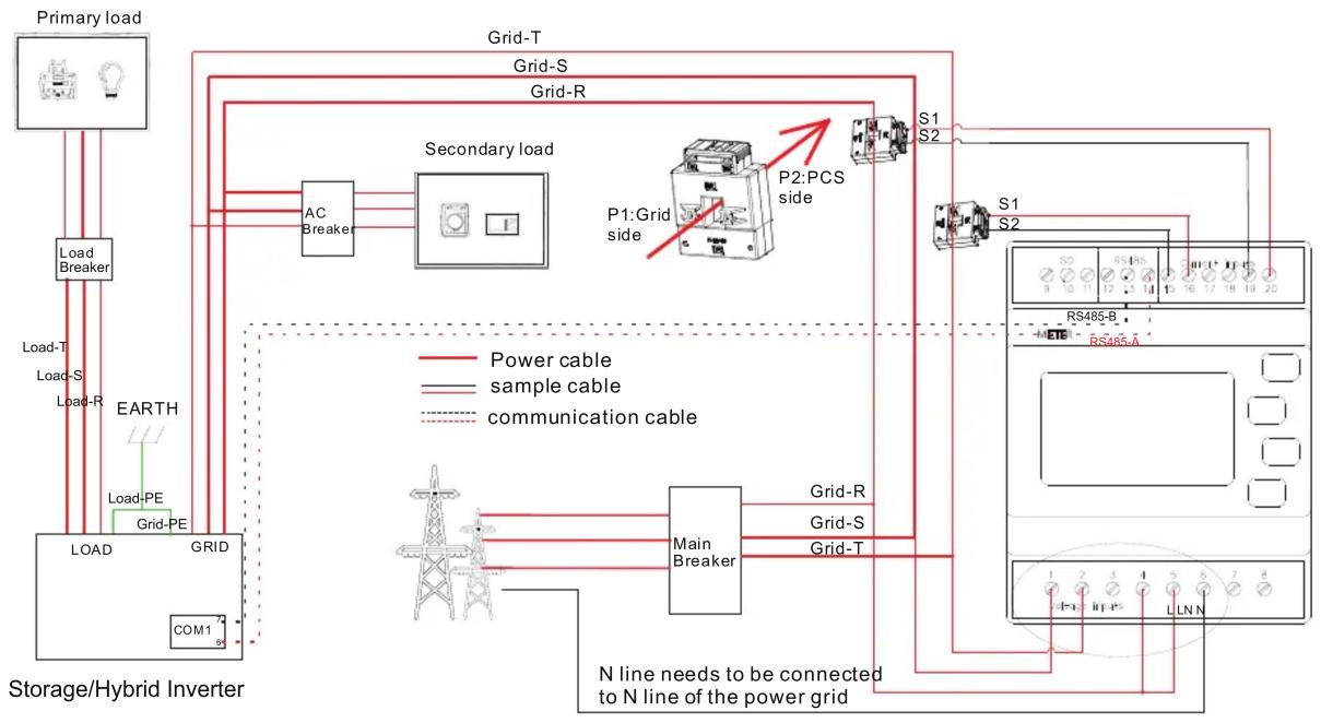
flowchart
graph TD
    A["Primary load"] --> B["Load Breaker"]
    B --> C["Load-T"]
    B --> D["Load-S"]
    B --> E["Load-R"]
    C --> F["EARTH"]
    D --> G["Load-PE"]
    E --> H["Load-PE"]
    F --> I["GRID"]
    G --> J["GRID-PE"]
    H --> K["GRID"]
    L["Storage/Hybrid Inverter"] --> M["COM1"]
    M --> N["AC Breaker"]
    N --> O["Secondary load"]
    O --> P["P1:Grid side"]
    P --> Q["P2:PCS side"]
    Q --> R["S1 S2"]
    R --> S["S1 S2"]
    S --> T["RS485-B"]
    T --> U["METER RS485-A"]
    U --> V["N line needs to be connected to N line of the power grid"]
    V --> W["Main Breaker"]
    W --> X["Grid-R"]
    W --> Y["Grid-S"]
    W --> Z["Grid-T"]
    X --> AA["Power cable"]
    Y --> AB["sample cable"]
    Z --> AC["communication cable"]
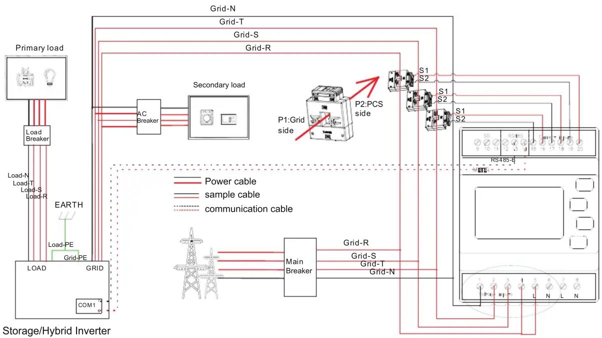
flowchart
graph TD
    A["Primary load"] --> B["Load Breaker"]
    B --> C["Load-N"]
    B --> D["Load-T"]
    B --> E["Load-S"]
    B --> F["Load-R"]
    C --> G["EARTH"]
    D --> H["Load-PE"]
    E --> I["Load-PE"]
    F --> J["Load-PE"]
    G --> K["GRID"]
    H --> L["GRID"]
    I --> M["GRID"]
    K --> N["COM1"]
    L --> O["GRID-N"]
    M --> P["GRID-T"]
    N --> Q["Grid-S"]
    O --> R["Grid-R"]
    P --> S["Secondary load"]
    Q --> T["Secondary load"]
    R --> U["AC Breaker"]
    S --> V["P1:Grid side"]
    T --> W["P2:PCS side"]
    U --> X["S1 S2"]
    V --> Y["S1 S2"]
    W --> Z["S1 S2"]
    X --> AA["S0 RS485-B ETE"]
    Y --> AB["S0 RS485-B ETE"]
    Z --> AC["S0 RS485-B ETE"]
8. 56 Communication module installation Service and contact
Shenzhen Growatt New Energy Co., Ltd.
4-13/F, Building A, Sino-German (Europe) Industrial Park, Hangcheng Blvd, Bao'an District, Shenzhen, China
T +86 755 2747 1942
E service@ginverter.com
W www.ginverter.com

Download Manual


Growatt New Energy


Brand : Growatt
Model : TPM-CT-E-EU
Category : Uncategorized