
D ONE - Receiver Helix - Free user manual and instructions
Find the device manual for free D ONE Helix in PDF.


| Product Type | Digital Satellite Receiver |
| Brand | Helix |
| Model | D ONE |
| Dimensions (W x D x H) | 200 x 140 x 40 mm |
| Weight | 0.5 kg |
| Power Supply | DC 12V, 1A |
| Power Consumption | 10 W (max) |
| Video Output | HDMI, Composite (RCA) |
| Audio Output | Digital Optical, Analog RCA |
| Supported Video Formats | MPEG-2, MPEG-4, H.264 |
| Supported Audio Formats | MPEG-1, MPEG-2, Dolby Digital |
| Channel Capacity | Up to 5,000 TV and radio channels |
| Satellite Input | F-type connector, 75 Ohm |
| Remote Control | Infrared, batteries included |
| Interface Languages | Multiple languages (EN, DE, FR, etc.) |
| EPG (Electronic Program Guide) | 7-day, with timer recording |
| Parental Control | Channel locking with PIN |
| USB Port | 1 x USB 2.0 for multimedia playback |
| Cleaning | Wipe with a soft, dry cloth; do not use liquids |
| Safety | Keep away from humidity, heat, and direct sunlight |
| Spare Parts | Remote control, power adapter, RCA cable |
Frequently Asked Questions - D ONE Helix
User questions about D ONE Helix
0 question about this device. Answer the ones you know or ask your own.
Ask a new question about this device
Download the instructions for your Receiver in PDF format for free! Find your manual D ONE - Helix and take your electronic device back in hand. On this page are published all the documents necessary for the use of your device. D ONE by Helix.
USER MANUAL D ONE Helix
natural_image
Black HELIX IONE device with visible branding and control buttons (no readable text beyond branding)D ONE
1-channel Class D amplifier
line
| Phase | Value | | --------- | ----- | | 0° | 0 | | 180° | 0 |⑤ Bass Boost
⑩ Mono Cinch In- / Output
⑫ Power & Protect LED
Mono
Congratulations on your purchase of this innovative and high-qual ity HELIX product.
The HELIX D ONE combines best quality, excellent manufacturing and state-of-the-art technology.
Thanks to more than 30 years of experience in research and development of audio products this amplifier generation sets new standards with respect to price /performance ratio.
We wish you many hours of enjoyment with your new HELIX amplifier.
Yours,
AUDIOTEC FISCHER Team
General instructions
General installation instructions for HELIX components
To prevent damage to the unit and possible injury, read this manual carefully and follow all installation instructions. This product has been checked for proper function prior to shipping and is guaranteed against manufacturing defects.
Before starting your installation, disconnect the battery's negative terminal to prevent damage to the unit, fire and/or risk of injury. For a proper performance and to ensure full warranty coverage, we strongly recommend to get this product installed by an authorized HELIX dealer.
Install your D ONE in a dry location with sufficient air circulation for proper cooling of the equipment. The amplifier should be secured to a solid mounting surface using proper mounting hardware. Before mounting, carefully examine the area around and behind the proposed installation location to ensure that there are no electrical cables or components, hydraulic brake lines or any part of the fuel tank located behind the mounting surface. Failure to do so may result in unpredictable damage to these components and possible costly repairs to the vehicle.
General instruction for connecting the HELIX D ONE amplifier
The HELIX D ONE amplifier may only be installed in vehicles which have a 12 Volts negative terminal connected to the chassis ground. Any other system could cause damage to the amplifier and the electrical system of the vehicle.
The positive cable from the battery for the complete system should be provided with a main fuse at a distance of max. 30 cm from the battery. The value of the fuse is calculated from the maximum total current input of the car audio system.
Use only suitable cables with sufficient cable cross-section for the connection of the HELIX D ONE. The fuses may only be replaced by identically rated fuses (2 x 30 A) to avoid damage of the amplifier.
Prior to installation, plan the wire routing to avoid any possible damage to the wire harness. All cabling should be protected against possible crushing or pinching hazards. Also avoid routing cables close to potential noise sources such as electric motors, high power accessories and other vehicle harnesses.
Connectors and control units
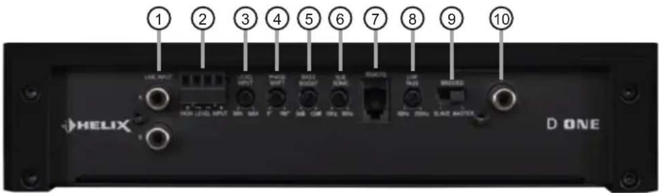
① Line Input
RCA inputs for connecting lowlevel line signals.
② Highlevel Input
Highlevel speaker inputs for connecting a factory radio or an aftermarket radio without lowlevel line outputs.
③ Level Input
Control for adjusting the input sensitivity of the lowlevel Line and Highlevel Inputs.
④ Phase Shift
Control for adjusting the phase from 0^ to 180^ .
⑤ Bass Boost
Control for adjusting the bass boost from 0 to 12 dB.
⑥ Subsonic
Control for adjusting the subsonic filter from 10 to 50 Hz.
⑦ Remote
Input for connecting the included cable remote control for volume adjustment.
⑧ LPF
Control for adjusting the lowpass filter from 50 to 250 Hz.
⑨ Master / Slave Mode
Switch for operating two D ONE amplifiers in bridge mode.
10 Mono RCA/Cinch In-/Output
Mono RCA/Cinch signal in- or output for bridge mode operation in Master / Slave Mode.
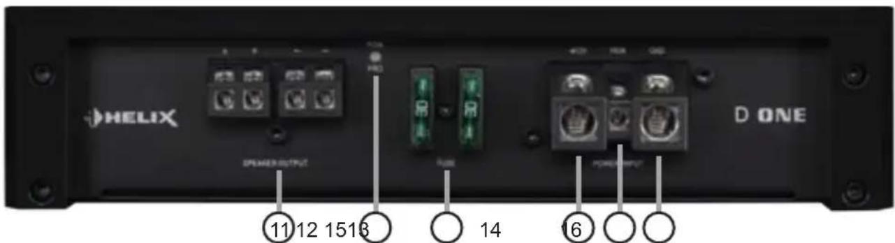
11 Speaker Output
Speaker outputs for connecting subwoofers.
12 Power & Protect LED
This LED indicates the operating mode of the amplifier.
⑬ Fuse
Input fuses - 2 x 30 Ampere.
14 +12 V
Connector for the +12 V power cable of the positive terminal of the battery.
15 REM
Connector for the remote cable.
16 GND
Connector for the ground cable (negative terminal of the battery or metal body of the vehicle).
Initial start-up and functions
① Line Input
2-channel lowlevel line input to connect signal sourc es such as head units / radios / DSPs.
Important: It is strictly forbidden to use the High-level Input and lowlevel Line Input at the same time. This may cause severe damage to the lowlevel line outputs of your head unit / car radio.
② Highlevel Input
2-channel highlevel loudspeaker input to connect the amplifier directly to the loudspeaker outputs of OEM / aftermarket radios that do not have any low-level line outputs.
The Highlevel Input is equipped with our proprietary ADEP circuit (Advanced Diagnostics Error Protection) which ensures that the car radio detects the amplifier as a speaker and thus neither any function of the radio (e.g. fader) will be deactivated nor any error log in the CPU of the car will be created. If this input is used the remote input (REM) does not need to be connected as the amplifier will automatically turn on once a loudspeaker signal is applied.
Attention: Solely use the pluggable screw-terminal for the highlevel connector which is included in delivery!
Important: It is strictly forbidden to use the High-level Input and lowlevel Line Input at the same time. This may cause severe damage to the lowlevel line outputs of your car radio.
③ Level Input
This control is used to adapt the input sensitivity to the output voltage of the connected signal source.
This is not a volume control, it's only for adjusting the amplifier gain. The control range of the RCA / Line Input (lowlevel) is 0.5 - 6 Volts and 1 - 14 Volts for the Highlevel Input.
If the Highlevel Input is used in combination with a standard car radio we recommend an input sensitivity of roughly 9 Volts. For this purpose, turn the control from max. CCW position to 9 o'clock position.
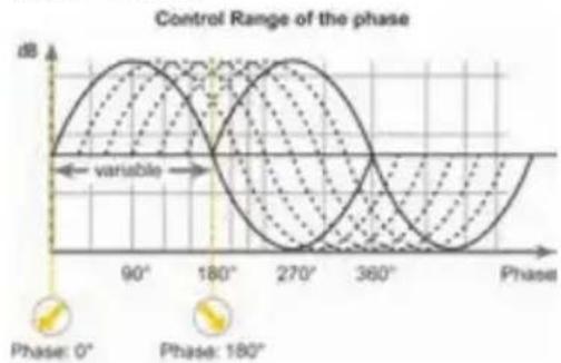
④ Phase Shift
This control is used to adjust the phase from 0^ to 180^ . This allows to match the phase of the subwoofer with the other speakers thus avoiding any cancellations in the frequency response due to
phase shifts.
line
| Phase | Value | | ----------- | ----- | | 0° | 0 | | 180° | 0 |⑤ Bass Boost
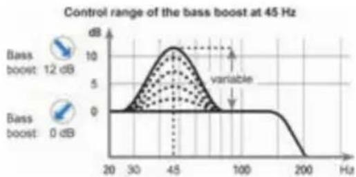
This control is used to increase the bass response at a center frequency of 45 Hz from 0 to 12 dB.
line
| Bass boost | Frequency (Hz) | | ---------- | -------------- | | 12 dB | 45 | | 0 dB | 200 |⑥ Subsonic
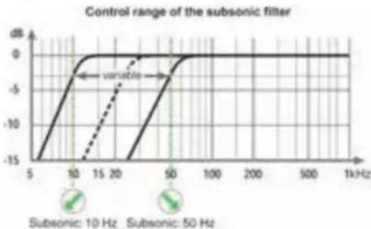
This control is used to adjust the crossover frequency of the subsonic filter from 10 Hz to 50 Hz. The subsonic filter cuts off very low frequencies which aren't audible and therefore relieves the amplifier and also the subwoofer. Additionally the amplifier will have more power available for the audible frequencies. This control is always activated and its adjustment is mandatory.
line
| Frequency | Subsonic: 10 Hz (dB) | Subsonic: 50 Hz (dB) | | --------- | -------------------- | -------------------- | | 5 | -15 | -15 | | 10 | -5 | -10 | | 20 | 0 | -5 | | 50 | 0 | 0 | | 100 | 0 | 0 | | 200 | 0 | 0 | | 500 | 0 | 0 | | 1kHz | 0 | 0 |⑦ Remote
This input is used to connect the included remote control. The remote control allows you to control the volume of the amplifier.
Initial start-up and functions
⑧ LPF
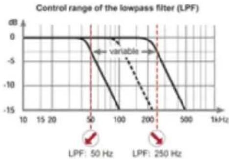
This control is used to adjust the crossover frequency of the lowpass filter from 50 Hz to 250 Hz. This control is always activated and its adjustment is mandatory.
line
| Frequency | Value | | --------- | ----- | | 50 Hz | -5 | | 250 Hz | -15 |In combination with the subsonic filter, the lowpass filter creates a bandpass in any case. By adjusting the subsonic (control 6) and lowpass (control 8) filter any bandpass between 10 Hz and 250 Hz can be realized.
Caution: To avoid a loss of gain make sure that the crossover frequencies of the subsonic and lowpass filters do have an interval of at least two octaves when generating a bandpass. That means if the lowpass is adjusted to 100 Hz the subsonic should be adjusted to 25 Hz or less (one octave = doubled frequency or halved frequency).
⑨ Master / Slave Mode
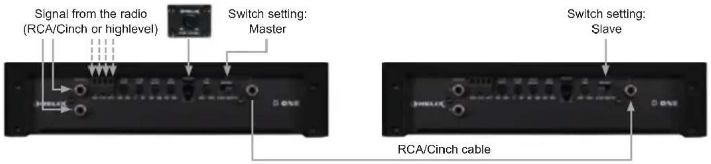
The HELIX D ONE amplifier is a “real-mono” amplifier and can be connected to a second D ONE via the Master / Slave Mode by which the output power is more than doubled, depending on the speaker configuration. In order to operate two amplifiers in this mode, they must be connected with a RCA / Cinch cable (see page 14, item 10; Mono Cinch In-/Output). The amplifier which is set as “Master” assumes the complete control (active crossover, bass boost etc.) for both amps. All filter adjustments of the amplifier which operates in “Slave” mode will be deactivated.
Attention: Make sure that one amplifier is adjusted as "Master" and the other one as "Slave". In this mode the minimum speaker impedance is 2 Ohms.
Note: If the amplifier operates individually the Master / Slave Mode switch must be set to "Master".
⑩ Mono Cinch In- / Output
This connector serves as signal in- or -output for connecting a further D ONE amplifier in bridge mode (see page 14, item 9; Master / Slave Mode).
⑪ Speaker Output
Speaker outputs to connect a subwoofer. The minimum load impedance must not be lower than 1 Ohm (2 Ohms in Master / Slave Mode).
⑫ Power & Protect LED
The power and protect LED indicates the operating mode of the amplifier.
Green: The amplifier is ready for operation.
Red: A malfunction has occurred. A malfunction
may have different causes as the HELIX D ONE is equipped with several protection circuits. These protections shut off the amplifier in case of overheating, over- and undervoltage, short-circuit on loudspeakers and false connection. Please check for connecting failures such as short-circuits, wrong connections, wrong adjustments and over temperature. If the amplifier does not turn on it is defective and has to be sent to your local authorized dealer for repair service. A detailed description of the malfunction and the purchase receipt has to be attached.
⑬ Fuse
The input fuses are connected in parallel and provide protection against an internal fault of the device, therefore the system must be additionally protected by a further main fuse located close to the battery (max. distance from battery: 30 cm / 12"). The HELIX D ONE is equipped with 2 x 30 Ampere fuses.
⑭ +12 V
Connect the +12 V power cable to the positive terminal of the battery. Recommended cross section: min. 10 mm ^4 / AWG 8.
15 REM
The remote lead should be connected to the remote output / automatic antenna (aerial positive) output of the head unit / car radio. This is only activated if the head unit is switched on. Thus the amplifier is switched on and off together with the head unit / car radio. This input needn't to be assigned if the
Highlevel Input is used.

GND
The ground cable should be connected to a common ground reference point (this is located where the negative terminal of the battery is grounded to the metal body of the vehicle) or to a prepared metal location on the vehicle chassis i.e. an area which has been cleaned of all paint residues. Recommended cross section: min. 10 mm ^2 / AWG 8.
Installation
Connection of HELIX D ONE to the head unit / car radio:
Caution: Carrying out the following steps will require special tools and technical knowledge. In order to avoid connection mistakes and / or damage, ask your dealer for assistance if you have any questions and follow all instructions in this manual (see page 11). It is recommended that this unit will be installed by an authorized HELIX dealer.
1. Connecting the lowlevel line inputs
Use the correct cable (RCA / Cinch cable) to connect these inputs to the lowlevel line outputs of your car radio. It is mandatory to use both lowlevel line inputs.
The automatic turn-on circuit does not work when using the lowlevel line inputs. In this case the remote input (REM) has to be connected to activate the HELIX D ONE.
Important: It is strictly forbidden to use the Highlevel Input and lowlevel Line Input at the same time. This may cause severe damage to the lowlevel line outputs of your car radio.
2. Connecting the highlevel speaker inputs
The highlevel loudspeaker inputs can be connected directly to the loudspeaker outputs of an OEM or aftermarket radio using appropriate cables (loudspeaker cables with 1 mm^2 / AWG 18 max. ).
It is mandatory to use both highlevel speaker inputs. Make sure that the polarity is correct. If one connection has reversed polarity it may affect the performance of the amplifier. If this input is used the remote input (REM) does not need to be connected as the amplifier will automatically turn on once a loudspeaker signal is applied.
3. Adjustment of the input sensitivity
Attention: It is mandatory to properly adapt the input sensitivity of the D ONE to the signal source in order to avoid damage to the amplifier.
If you want to change the input sensitivity use the Level Input control (see page 13, item 3; Level Input). The setting of the control affects both the lowlevel line inputs (LineInput) and the highlevel speaker inputs (Highlevel Input)!
If the HighlevelInput is used in combination with a standard car radio we recommend an input sensitivity of roughly 9 Volts. For this purpose, turn the control from max. CCW position to 9 o'clock position.
4. Connection to power supply
Make sure to disconnect the battery before installing the HELIX D ONE!
Connect the +12 V power cable to the positive terminal of the battery. The positive wire from the battery to the amplifier power terminals needs to have an inline fuse at a distance of less than 12 inches (30 cm) from the battery. The value of the fuse is calculated from the maximum total current draw of the whole car audio system (D ONE = max. 60 A RMS at 12 V power supply). If your power wires are short (less than 1 m / 40") then a wire gauge of 10 mm² / AWG 8 will be sufficient. In all other cases we strongly recommend gauges of 16 - 25 mm² / AWG 6 - 4!
The ground cable (same gauge as the +12 V wire) should be connected to a common ground reference point (this is located where the negative terminal of the battery is grounded to the metal body of the vehicle), or to a prepared metal location on the vehicle chassis, i.e. an area which has been cleaned of all paint residues.
5. Connecting the remote input
The remote input (REM) has to be connected to the radio remote output if the amplifiers low-level line inputs are used as signal inputs. We do not recommend controlling the remote input via the ignition switch to avoid pop noise during turn on/off.
If the Highlevel Input is used this input does not need to be connected as long as the car radio has BTL output stages.
6. Connecting an amplifier in Master / Slave mode (optional)
For connecting a further D ONE amplifier in bridge mode follow the subsequent steps:
-
Define the amplifier which is connected to the signal source (radio) as "Master" by setting the Master / Slave Mode switch to "Master" (see page 14, item 9, Master / Slave Mode).
-
SettheMaster / Slave Mode switch of the second amplifier to "Slave".
-
Connect the Mono Cinch In-/Outputs of the amplifiers by using an appropriate RCA / Cinch cable (see page 14, item 10; Mono Cinch In-/Output).
-
Make all filter settings on the amplifier in
“Master” mode. All filter adjustments of the amplifier which operates in “Slave” mode will be deactivated.
Examples of configurations can be found on page 18.
7. Connecting the loudspeaker outputs
The loudspeaker outputs can be connected directly to the wires of the loudspeakers.
Note: Outputs are wired in parallel internally. This means that both plus outputs (+) and both minus outputs (-) deliver the same output signal.
Never connect any of the loudspeaker cables to the chassis ground as this will damage your amplifier and your speakers.
If you connect two loudspeakers in parallel ensure that they are correctly connected (in phase), i.e. plus to plus and minus to minus. Exchanging plus and minus causes a total loss of bass reproduction. The positive terminal is indicated on most speakers. The minimum load impedance must not be lower than 1 Ohm, otherwise the amplifier protection will be activated. Examples for speaker configurations can be found on page 16 et sqq.
Examples for speaker configurations
Mono
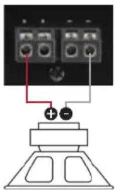
Subwoofer with one voice coil (single voice coil)
Maximum output power of this configuration:
1 x 4 Ohms: 200 / 400 Watts
1 x 2 Ohms: 340 / 680 Watts
1 x 1 Ohm: 530 / 1,060 Watts
Parallel operation
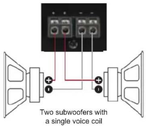
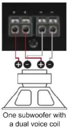
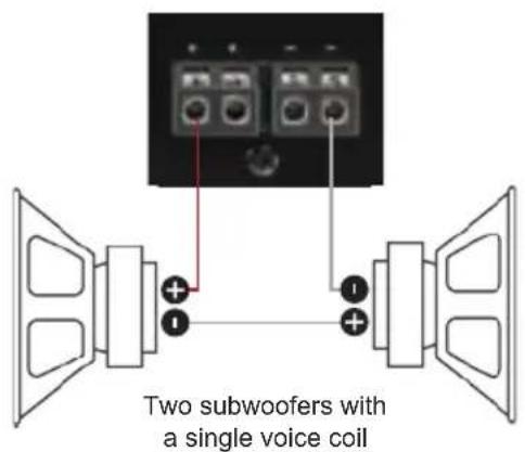
Two subwoofers with one voice coil (single voice coil) or one subwoofer with dual voice coil are connected in parallel.
Note: The parallel connection of two voice coils will result in halving the impedance!
Maximum output power of this configuration:
Two subwoofers with 1 x 4 Ohms correspond to a total impedance of 2 Ohms: 340 / 680 Watts
One subwoofer with 2 x 4 Ohms also corresponds to a total impedance of 2 Ohms: 340 / 680 Watts
Two subwoofers with 1 x 2 Ohms correspond to a total impedance of 1 Ohm: 530 / 1,060 Watts
One subwoofer with 2 x 2 Ohms also corresponds to a total impedance of 1 Ohm: 530 / 1,060 Watts
Note: The parallel connection of 1 Ohm voice coils will result in shutdown of the amplifier.
In series
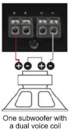
Two subwoofers with one voice coil (single voice coil) or one subwoofer with dual voice coil are connected in series.
Note: The connection of two voice coils in series will result in doubling the impedance!
Maximum output power of this configuration:
Two subwoofers with 1 x 2 Ohms correspond to a total impedance of 4 Ohms: 200 / 400 Watts
One subwoofer with 2 x 2 Ohms also corresponds to a total impedance of 4 Ohms: 200 / 400 Watts
Two subwoofers with 1 x 1 Ohm correspond to a total impedance of 2 Ohms: 340 / 680 Watts
One subwoofer with 2 x 1 Ohm also corresponds to a total impedance of 2 Ohms: 340 / 680 Watts
Note: The connection of subwoofers with 4 Ohms in series results in a low output power of the amplifier!
Example configurations for Master / Slave Mode
Amplifier connection in Master / Slave Mode
Master Slave
Speaker connection in Master / Slave Mode
Master Slave
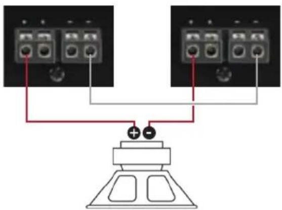
One subwoofer with one voice coil
(single voice coil)
Maximum output power of this configuration:
1 x 4 Ohms: 645 / 1,290 Watts
1 x 2 Ohms: 910 / 1,820 Watts
Note: The negative terminals of both amplifiers have to be connected by using a speaker wire. The size should be similar to the speaker wires which are used for the subwoofer connection.
Master Slave
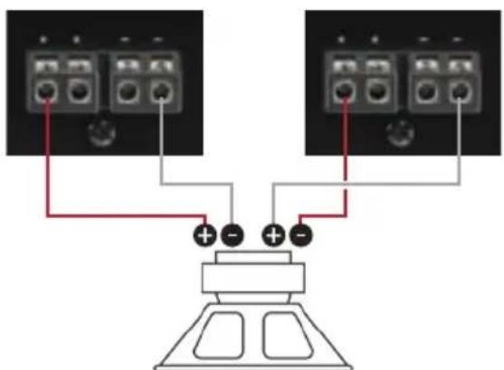
Attention: The second voice coil of the subwoofer must be connected in reversed polarity to the amplifier which is adjusted as "Slave"!
One subwoofer with dual voice coil
(dual voice coil)
Maximum output power of this configuration:
2 x 4 Ohms: 400 / 800 Watts
2 x 2 Ohms: 680 / 1,360 Watts
2 x 1 Ohm: 1,060 / 2,120 Watts
Note: In this configuration example an 1 Ohm configuration in Master / Slave Mode is possible but not advisable!
Technical Data
Output power RMS / max. Normal operation Master / Slave Mode (One amplifier) (Two amplifiers)
- @ 4 Ohms....1 x 200 / 400 Watts 1 x 645 / 1,290 Watts
- @ 2 Ohms....1 x 340 / 680 Watts 1 x 910 / 1,820 Watts
- @ 1 Ohm.... 1 x 530 / 1,060 Watts -
Amplifier technology .... Class D
Inputs....2 x RCA / Cinch
2 x Highlevel speaker input
1 x Remote In
1 x Remote control input
Outputs.... 1 x Speaker output
Frequency response....10 Hz - 250 Hz
Bass boost....0 - 12 dB / 45 Hz
Lowpass 50 Hz - 250 Hz adjustable
Bandpass.... 10 Hz - 250 Hz adjustable
Subsonic.... 10 Hz - 50 Hz adjustable
Phase 0 - 180° adjustable
Slope subsonic / lowpass 12 dB/Oct.
Distortion (THD)....0.25 %
Signal-to-noise ratio.... 95 dB (A-weighted)
Input sensitivity....Highlevel 1 - 14 Volts
RCA / Cinch 0.5 - 6 Volts
Damping factor 100
Input impedance RCA / Cinch 30 kOhms
Input impedance highlevel....12 Ohms
Operating voltage 9.6 - 16 Volts
Fuse.... 2 x 30 A Maxi-fuse (APX)
Dimensions (H x W x D) 53 x 250 x 230 mm / 2.09 x 9.84 x 9.06"
Additional features....Active, adjustable crossover, bass boost, phase shift, Master / Slave Mode switch, highlevel input with automatic turn on function and Advanced Diagnostics Error Protection (ADEP), bass volume cable remote control
Warranty Disclaimer
The limited warranty comply with legal regulations. Failures or damages caused by overload or improper use are not covered by the warranty. Please return the defective product only with a valid proof of purchase and a detailed malfunction description. Technical specifications are subject to change!
Errors are reserved! For damages on the vehicle and the device, caused by handling errors of the device, we can't assume liability. These devices are certified for the use in vehicles within the European Community (EC).
AUDIOTEC
FISCHER
- D ONE
- ⑤ Bass Boost
- ⑩ Mono Cinch In- / Output
- ⑫ Power & Protect LED
- Mono
- General instructions
- General installation instructions for HELIX components
- General instruction for connecting the HELIX D ONE amplifier
- Connectors and control units
- ① Line Input
- ② Highlevel Input
- ③ Level Input
- ④ Phase Shift
- ⑥ Subsonic
- ⑦ Remote
- ⑧ LPF
- ⑨ Master / Slave Mode
- Mono RCA/Cinch In-/Output
- Speaker Output
- Power & Protect LED
- ⑬ Fuse
- +12 V
- REM
- GND
- Initial start-up and functions
- ⑪ Speaker Output
- ⑭ +12 V
- GND
- Installation
- Connection of HELIX D ONE to the head unit / car radio:
- Connecting the lowlevel line inputs
- Connecting the highlevel speaker inputs
- Adjustment of the input sensitivity
- Connection to power supply
- Connecting the remote input
- Connecting an amplifier in Master / Slave mode (optional)
- Connecting the loudspeaker outputs
- Examples for speaker configurations
- Parallel operation
- In series
- Example configurations for Master / Slave Mode
- Speaker connection in Master / Slave Mode
- One subwoofer with one voice coil
- One subwoofer with dual voice coil
- Technical Data
- Warranty Disclaimer
Brand : Helix
Model : D ONE
Category : Receiver