
CHNTDDSU666 - Uncategorized Deye - Free user manual and instructions
Find the device manual for free CHNTDDSU666 Deye in PDF.


| Product Type | Three-phase electronic energy meter (DIN-rail) |
| Models | DTSU666 (three-phase four-wire), DSSU666 (three-phase three-wire) |
| Dimensions | 100 × 72 × 65 mm (4 modules) |
| Mounting | DIN35 mm rail |
| Voltage (rated) | 3×230/400 V (DTSU666) or 3×400 V (DSSU666) |
| Current (direct) | 5(80) A |
| Current (transformer) | 1.5(6) A |
| Accuracy class (active) | Class 0.5S (1.5(6)A) or Class 1 (5(80)A) |
| Accuracy class (reactive) | Class 2 |
| Impulse constant | 6400 imp/kWh (1.5(6)A) or 400 imp/kWh (5(80)A) |
| Power consumption (voltage) | ≤1.5 W and 6 VA |
| Power consumption (current) | ≤0.2 VA (Ib<10A) or ≤0.4 VA (Ib≥10A) |
| Communication | RS485, protocols DL/T645-2007 or ModBus-RTU |
| Display | LCD, 7-digit energy display, backlit |
| Working temperature | -10°C to +45°C (extended -25°C to +75°C) |
| Relative humidity | ≤75% (annual average) |
| Data retention | ≥10 years after power interruption |
| Warranty | 18 months from delivery |
Frequently Asked Questions - CHNTDDSU666 Deye
User questions about CHNTDDSU666 Deye
0 question about this device. Answer the ones you know or ask your own.
Ask a new question about this device
Download the instructions for your Uncategorized in PDF format for free! Find your manual CHNTDDSU666 - Deye and take your electronic device back in hand. On this page are published all the documents necessary for the use of your device. CHNTDDSU666 by Deye.
USER MANUAL CHNTDDSU666 Deye
DTSU666 series three phase four wire electronic energy meter (Din-rail) DSSU666 series three phase three wire electronic energy meter (Din-rail)
Manual
ZTY0.464.1002
Zhejiang Chint Instrument & Meter Co., Ltd. June, 2019
Catalog
- Brief Introduction .... 1
- Working Principle.... 2
- Main Technical Performance & Parameters.... 3
- Main function....6
- Outline and installation size.... 12
- Installation and operation manual.... 13
- Diagnosis, analysis and elimination for common faults.... 16
- Transportation & Storage.... 17
- Maintenance & Service.... 17
| DTSU666 series and DSSU666 series three phase electronic energy meter(DIN-Rail) | ZTY0.464.1002 |
| Operation manual | Page 1, Total 18 |
1. Brief Introduction
1.1. Main application & applicable range
DTSU666 series three phase four wire and DSSU666 series three phase three wire electronic energy meter (din-rail) (hereinafter referred to as the “instrument”) is designed based on power monitoring and energy metering demands for electric power system, communication industry, construction industry, etc. as a new generation of intelligent instrument combining measurement and communication function, mainly applied into the measurement and display for the electric parameters in the electric circuit including three voltage, three current, active power, reactive power, frequency, positive& negative energy, four-quadrant energy, etc. Adopting the standard DIN35mm din rail mounting and modular design, it is characterized with small volume, easy installation and easy networking, widely applied into the internal energy monitoring and assessment for industrial and mining enterprises, hotels, schools, large public buildings.
Complied standards:
IEC 61010-1:2010《Safety requirements for electrical equipment for measurement, control and laboratory use Part1:General requirements》
IEC 61326-1:2013 《Electrical equipment for measurement, control and laboratory use –EMC requirements Part1:General requirements》
1.2. Product Features
1) Characterized with positive and reverse active power, combined active power, combined reactive power, four quadrant reactive power metering and storage function with combination mode character can be set.
| DTSU666 series and DSSU666 series three phase electronic energy meter(DIN-Rail) | ZTY0.464.1002 |
| Operation manual | Page 2, Total 18 |
2) RS485 communication interface, easy to exchange data with outside;
3) Adopting the standard DIN35mm din rail mounting and modular design, it is characterized with small volume, easy installation and easy networking.
1.3. Product Model
Table 1 product model and specification
| Model | voltage (V) | Current (A) | Impulse constant | Accuracy class | |
| imp/kWh | imp/kvarh | ||||
| DTSU666 | 3×230/400 | 1.5(6)A | 6400 | 6400 | Active Class 0.5S, Reactive Class 2 |
| 5(80)A | 400 | 400 | Active Class 1, Reactive Class 2 | ||
| DSSU666 | 3×400 | 1.5(6)A | 6400 | 6400 | Active Class 0.5S, Reactive Class 2 |
| 5(80)A | 400 | 400 | Active Class 1, Reactive Class 2 | ||
Note: 1.5(6)A is Connection through current transformers, 5(80)A is direct access.
1.4. Temperature range
Regulated working temperature range: -10^ +45^ ;
Limited working temperature range: -25^ +75^ ;
Relative humidity(Annually average):≤75%;
Atmospheric pressure: 63.0kPa\~106.0kPa( altitude 4km and below), excepting the requirements for special orders.
2. Working Principle
2.1. Working Principle
The instrument are composed of high accurately integrated circuit specially for measurement (ASIC) and managing MCU, memory chip, RS485 communication module, etc.
| DTSU666 series and DSSU666 series three phase electronic energy meter(DIN-Rail) | ZTY0.464.1002 |
| Operation manual | Page 3, Total 18 |
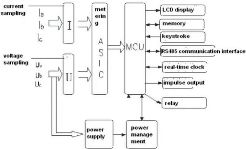
flowchart
graph TD
    A["current sampling"] --> B["I"]
    C["voltage sampling"] --> D["U"]
    B --> E["metering"]
    D --> E
    E --> F["MCU"]
    F --> G["LCD display"]
    F --> H["memory"]
    F --> I["keystroke"]
    F --> J["RS485 communication interface"]
    D --> K["Uo"]
    D --> L["Ub"]
    D --> M["Uc"]
    K --> N["real-time clock"]
    L --> N
    M --> O["impulse output"]
    N --> P["relay"]
    O --> P
    P --> Q["power management"]
    Q --> R["power supply"]
    R --> D
Figure 1 Working principle block diagram Figure 1
2.2. Principle for the main function module
The special metering integrated circuit (ASIC) integrated six load two order - type of A/D conversion, please take the digital signal processing measured by the voltage circuit as well as all the power, energy, effective values, power factor and frequency. This metering chip can measure the active power, reactive power, apparent power, active energy, reactive power, apparent energy of each phase and combined phase, and at the same time measuring current, voltage effective values, power factor, phase angle, frequency and other parameters, entirely satisfying the needs of power meter. The chip provides an SPI interface, convenient for metering parameters as well as parameter calibration between the management MCU.
3. Main Technical Performance & Parameters
3.1. limit of error caused by the current augment
Table 2 The limit value of the active percentage error of meters on balanced load
| Meters for | Value of current | Power factor | Percentage error limitsfor meters of class | ||
| 0.5S | Class 1 | Class 2 | |||
| Connection throughcurrent transformers | 0.01I_n ≤ I < 0.05I_n | 1 | ±1.0 | ±1.5 | ±2.0 |
| 0.05I_n ≤ I ≤ I_max | 1 | ±0.5 | ±1.0 | ±1.2 | |
| 0.02I_n ≤ I < 0.1I_n | 0.5L、0.8C | ±1.0 | ±1.5 | ±2.0 | |
| 0.1I_n ≤ I ≤ I_max | 0.5L、0.8C | ±1.0 | ±1.0 | ±1.2 | |
| DTSU666 series and DSSU666 series three phase electronic energy meter(DIN-Rail) | ZTY0.464.1002 |
| Operation manual | Page 4, Total 18 |
| Direct connection | 0.05I_b ≤ I < 0.1I_b | 1 | - | ±1.5 | ±2.0 |
| 0.1I_b ≤ I ≤ I_max | 1 | - | ±1.0 | ±1.2 | |
| 0.01I_b ≤ I < 0.2I_b | 0.5L、0.8C | - | ±1.5 | ±2.0 | |
| 0.2I_b ≤ I ≤ I_max | 0.5L、0.8C | - | ±1.0 | ±1.2 | |
| Note | In: secondary rated current of the current transformer; Ib: calibrated current of the meter;L:inductive; C: capacitive; | ||||
Table 3 The limit value of the reactive percentage error of meters on balanced load
| Value of current | (inductive or capacitive) | Percentage error limits for meters of class | |
| Direct connection | Connection through current transformers | Class 2 | |
| 0.05I_b ≤ I < 0.1I_b | 0.02I_n ≤ I < 0.05I_n | 1 | ±2.5 |
| 0.1I_b ≤ I ≤ I_max | 0.05I_n ≤ I ≤ I_max | 1 | ±2.0 |
| 0.1I_b ≤ I < 0.2I_b | 0.05I_n ≤ I < 0.1I_n | 0.5 | ±2.5 |
| 0.2I_b ≤ I ≤ I_max | 0.1I_n ≤ I ≤ I_max | 0.5 | ±2.0 |
| 0.2I_b ≤ I ≤ I_max | 0.1I_n ≤ I ≤ I_max | 0.25 | ±2.5 |
Table 4 The limit value of the reactive percentage error of meters on balanced load
| Value of current | Power factor | Percentage error limits for meters of class | |||
| Direct connection | Connection through | 0.5S | Class 1 | Class 2 | |
| 0.1 I_b ≤ I ≤ I_max | 0.05I_n ≤ I ≤ I_max | 1 | ±0.6 | ±2.0 | ±3.0 |
| 0.2I_b ≤ I ≤ I_max | 0.1I_n ≤ I ≤ I_max | 0.5L | ±1.0 | ±2.0 | ±3.0 |
Table 5 The limit value of the reactive percentage error of meters on imbalanced load
| Value of current | Power factor | Percentage error limits for meters of class | |
| Direct connection | Direct connection | Class 2 | |
| 0.1 I_b ≤ I ≤ I_max | 0.05I_n ≤ I ≤ I_max | 1 | ±3.0 |
| 0.2I_b ≤ I ≤ I_max | 0.1I_n ≤ I ≤ I_max | 0.5 | ±3.0 |
3.2. Starting and no-load condition
3.2.1. Starting
| DTSU666 series and DSSU666 series three phase electronic energy meter(DIN-Rail) | ZTY0.464.1002 |
| Operation manual | Page 5, Total 18 |
Under the power factor of 1.0 and started current, the instrument can be started and continuously measure (for multiple phase instrument, it will bring balanced load). If the instrument is designed based on measurement for dual directional energy, then it is applicable for each direction of energy.
Table 6 start current
| Meters for | Class of meter | Power factor | ||
| 0.5S | 1 | 2 | ||
| Direct connection | - | 0.004I_b | 0.005I_b | 1 |
| Connection through current transformers | 0.001I_b | 0.002I_b | 0.003I_b | 1 |
3.2.2. Test of no-load condition
When the voltage is applied with no current flowing in the current circuit, the test output of the meter shall not produce more than one pulse.
For this test, the current circuit shall be open-circuit and a voltage of 115 % of the reference voltage shall be applied to the voltage circuits.
The minimum test period t shall be
$$ \Delta t [ \min ] \frac {6 0 0 1 0 ^ {- 6}}{k m U I \cdot \quad \cdot_ {n} \quad \max} \quad \text { for meters of class 0.5S or 1 } $$
$$ \Delta t [ \min ] \frac {4 8 0 1 0 ^ {6}}{k \cdot m \cdot U _ {n} \cdot I _ {\max}} \quad \text { for meters of class 2 } $$
k is the number of pulses emitted by the output device of the meter per kilovarhour(imp/kvar·h); m is the number of measuring elements;
Un is the reference voltage in volts;
Imax is the maximum current in amperes.
3.3. Electrical parameters
Table 7 Electrical parameters
| Regulated operating voltage range | 0.9Un~1.1Un | |
| Extended operating voltage range | 0.8Un~1.15Un | |
| Power consumption of voltage | ≤1.5W 和 6VA | |
| Power consumption of current | Ib<10A | ≤0.2VA |
| Ib≥10A | ≤0.4VA | |
| Data storage time after power interruption | ≥10 years | |
| DTSU666 series and DSSU666 series three phase electronic energy meter(DIN-Rail) | ZTY0.464.1002 |
| Operation manual | Page 6, Total 18 |
4. Main function
4.1. Displayed function
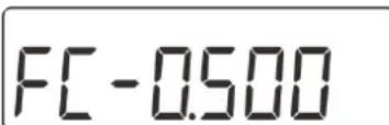
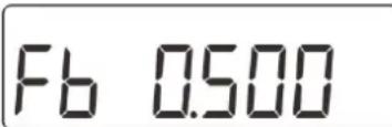
From the displayed interface, the electrical parameter and energy data are all primary side data (that is, the multiplied by current and voltage ratios). The energy measuring value will be displayed seven bits, with the displaying range from 0.00kWh to 9999999MWh.
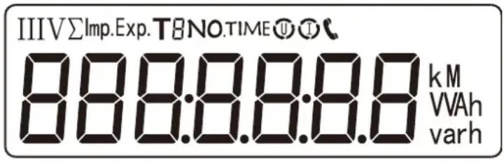
Figure 2 display
Table 8 Display interface
| No. | Display interface | Instruction | No. | Display interface | Instruction |
| 1 | 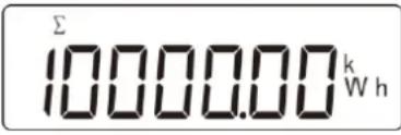 | Combined active energy =10000.00kWh | 11 | 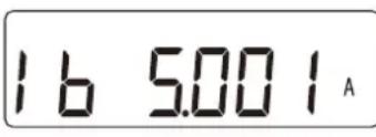 | Phase B current =5.001A |
| 2 | 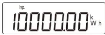 | Positive active energy =10000.00kWh | 12 | 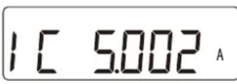 | Phase C current =5.002A |
| 3 | 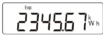 | Reserve active energy =2345.67kWh | 13 | 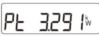 | Combined phase active power =3.291kW |
| 4 | 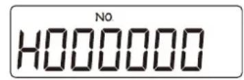 | Protocol: DT/L645-2007 address = 000000000001 | 14 | 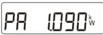 | Phase A active power =1.090kW |
| 5 | 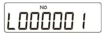 | 15 | 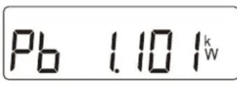 | Phase B active power =1.101kW |
| DTSU666 series and DSSU666 series three phase electronic energy meter(DIN-Rail) | ZTY0.464.1002 |
| Operation manual | Page 7, Total 18 |
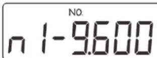
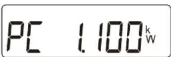
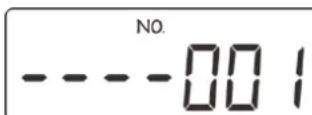
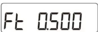
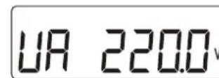
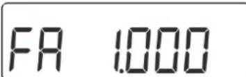
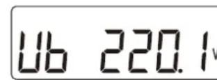
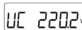
NOTE: Combined active energy = Positive active energy - Reserve active energy。
4.2. Programming function
4.2.1. Programming function
Table 9 Programming Parameter
| Parameter | Value range | Description |
| Ct | 1~9999 | Current ratio, used for setting the input loop current ratio:When the current is connected to the line via the transformer, Ct=the rated current of the primary loop / the rated current of the secondary circuit;When the current is directly connected to the line, Ct shall be set as 1. |
| Pt | 0.1~999.9 | Voltage ratio, used for setting the voltage ratio of the input loop;When the voltage is connected to the line via the transformer, Pt= the rated voltage of the primary loop / the rated voltage of the secondary circuit;When the voltage is directly connected to the line, Pt shall be set as 1.0. |
| Prot | 1: 645; | Settings for communication stop bit and Parity bits: |
| DTSU666 series and DSSU666 series three phase electronic energy meter(DIN-Rail) | ZTY0.464.1002 |
| Operation manual | Page 8, Total 18 |
| 2: n.2;3: n.1;4: E.1;5: O.1; | 1: Factory mode;2: None parity, 2 stop bits, n.2;3: None parity, 1 stop bit, n.1;4: Even parity, 1 stop bit, E.1;5: Odd parity, 1 stop bit, O.1; | |
| bRud | 0: 1.200;1: 2.400;2: 4.800;3: 9.600; | Communication baud rate:0: 1.200 bps;1: 2.400 bps;2: 4.800 bps;3: 9.600 bps; |
| Addr | 1~247 | Communication address |
| nEt | 0: n.34;1: n.33; | Option for wiring mode:0: n.34 represents three phase four wire;1: n.33 represents three phase three wire. |
| CLrE | 0:no; 1:E | The setting is 1, representing the allowed instrument energy data clearance, which will be zero reset after clearing. |
| Plus | 0:P; 1:Q;2:S; | Pulse output:0: active energy pulse; 1: reactive energy pulse; 2: Others. |
| dISP | 0~30 | Display in turns(second)0: Timely display; 1~30: Time interval of actual display. |
| bLcd | 0~30 | Backlight lighting time control (minutes)0: Normally light; 1~30: backlight lighting time without button operation |
4.2.2. Programming operation
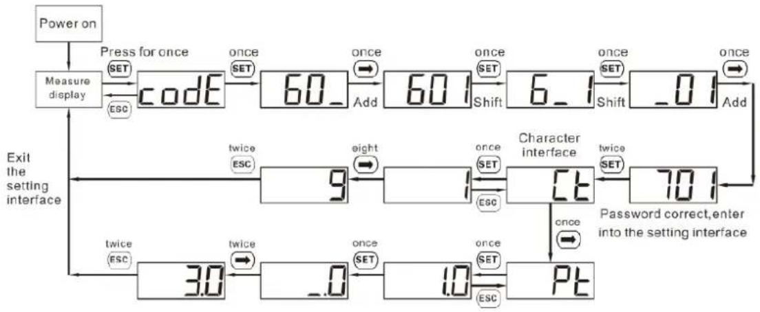
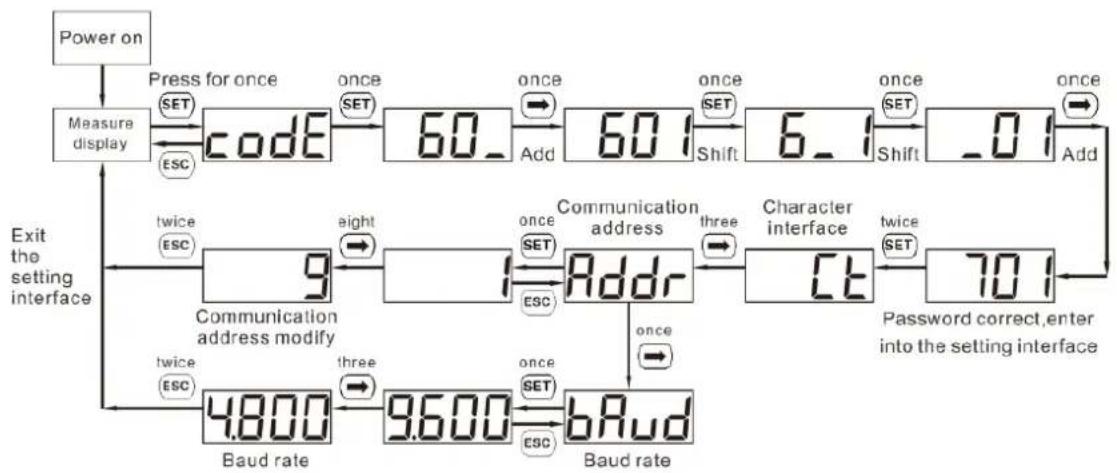
Button description: “SET” button represents “confirmation”, or “cursor shift” (when input digits), “ESC” button represents “exit”, “→” (“”) button represents “add”. The input code is (default 701).
| DTSU666 series and DSSU666 series three phase electronic energy meter(DIN-Rail) | ZTY0.464.1002 |
| Operation manual | Page 9, Total 18 |
flowchart
graph TD
    A["Power on"] --> B["Measure display"]
    B --> C["Code"]
    C --> D["60_"]
    D --> E["Shift"]
    E --> F["Character interface"]
    F --> G["70_"]
    G --> H["Password correct, enter into the setting interface"]
    H --> I["3.0"]
    I --> J["_.0"]
    J --> K["1.0"]
    K --> L["PT"]
    L --> M["twice ESC"]
    M --> N["9"]
    N --> O["twice ESC"]
    O --> P["60_"]
    P --> Q["Shift"]
    Q --> R["Character interface"]
    R --> S["twice SET"]
    S --> T["70_"]
    T --> U["Password correct, enter into the setting interface"]
    U --> V["twice ESC"]
    V --> W["3.0"]
    W --> X["_.0"]
    X --> Y["1.0"]
    Y --> Z["PT"]
    Z --> AA["twice SET"]
    AA --> AB["60_"]
    AB --> AC["Shift"]
    AC --> AD["Character interface"]
    AD --> AE["twice SET"]
    AE --> AF["70_"]
    AF --> AG["Password correct, enter into the setting interface"]
    AG --> AH["twice ESC"]
    AH --> AI["3.0"]
    AI --> AJ["_.0"]
    AJ --> AK["1.0"]
    AK --> AL["PT"]
Figure 3 Setting examples for current and potential transformer ratio
flowchart
graph TD
    A["Power on"] --> B["Measure display"]
    B --> C["Code"]
    C --> D["60_"]
    D --> E["Add"]
    E --> F["6_1"]
    F --> G["Shift"]
    G --> H["0_1"]
    H --> I["Add"]
    I --> J["Communication address modify"]
    J --> K["9"]
    K --> L["Address"]
    L --> M["3t"]
    M --> N["70_1"]
    N --> O["Password correct, enter into the setting interface"]
    O --> P["Baud rate"]
    P --> Q["4.800"]
    Q --> R["Three"]
    R --> S["9.600"]
    S --> T["Baud rate"]
    T --> U["9.600"]
    U --> V["Three"]
    V --> W["once SET"]
    W --> X["Baud rate"]
    X --> Y["Esc"]
    Y --> Z["Esc"]
    Z --> AA["Esc"]
    AA --> AB["Esc"]
    AB --> AC["Esc"]
    AC --> AD["Esc"]
    AD --> AE["Esc"]
    AE --> AF["Esc"]
    AF --> AG["Esc"]
    AG --> AH["Esc"]
    AH --> AI["Esc"]
    AI --> AJ["Esc"]
    AJ --> AK["Esc"]
    AK --> AL["Esc"]
    AL --> AM["Esc"]
    AM --> AN["Esc"]
    AN --> AO["Esc"]
    AO --> AP["Esc"]
    AP --> AQ["Esc"]
    AQ --> AR["Esc"]
    AR --> AS["Esc"]
    AS --> AT["Esc"]
    AT --> AU["Esc"]
    AU --> AV["Esc"]
    AV --> AW["Esc"]
    AW --> AX["Esc"]
    AX --> AY["Esc"]
    AY --> AZ["Esc"]
    AZ --> BA["Esc"]
    BA --> BB["Esc"]
    BB --> BC["Esc"]
    BC --> BD["Esc"]
    BD --> BE["Esc"]
    BE --> BF["Esc"]
    BF --> BG["Esc"]
    BG --> BH["Esc"]
    BH --> BI["Esc"]
    BI --> BJ["Esc"]
    BJ --> BK["Esc"]
    BK --> BL["Esc"]
    BL --> BM["Esc"]
    BM --> BN["Esc"]
    BN --> BO["Esc"]
    BO --> BP["Esc"]
    BP --> BQ["Esc"]
    BQ --> BR["Esc"]
    BR --> BS["Esc"]
    BS --> BT["Esc"]
    BT --> BU["Esc"]
    BU --> BV["Esc"]
    BV --> BW["Esc"]
    BW --> BX["Esc"]
    BX --> BY["Esc"]
    BY --> BZ["Esc"]
Figure 4 Setting examples for communication address and Baud Rate
When input digits, “” can be used as cursor “” motion button; “” is “add” button, “” is Exit the programming operation interface or switch to the character interface from digit modification interface, add from the beginning after setting the digit to the maximum value.
4.3. Communication function
Characterized with a RS485 communication interface, the baud rate can be changed between 1200bps, 2400bps, 4800bps and 9600bps. It conforms to DL/T645-2007
Factory default communication parameters is DL/T 645-2007 protocol, the default baud rate is 2400bps, with the calibration bit and stop bit to be E.1 and instrument address (please see instrument factory number or crystal display screen).
| DTSU666 series and DSSU666 series three phase electronic energy meter(DIN-Rail) | ZTY0.464.1002 |
| Operation manual | Page 10, Total 18 |
Customized communication parameter is ModBus-RTU protocol, the baud rate is 9600bps, with the calibration bit and stop bit to be n.1, and the instrument address to be 1. The following table is the common ModBus protocol address table, can be asked for specified communication protocol by calling. ModBus_RTU protocol read command is 03H, write command is 10H.
Table 10 ModBus protocol address table
| Parameter address | Parameter code | Instructions of parameters | Data type | Data length Word | Read Write |
| Keyboard parameters (specific parameters see the instructions of programming parameters, the actual value with (*) parameter= communication parameter value × 0.1) | |||||
| 0000H | REV. | Version No. | 16 bit with Signed char | 1 | R/W |
| 0001H | UCode | Programming code codE(1~9999) | 16 bit with | 1 | R/W |
| 0002H | ClrE | Power reset CLr.E(1:energy clear) | Signed char | 1 | R/W |
| 0003H | net | Network selection (0:three phase four wire,1:three phase three wire) | 16 bit with | 1 | R/W |
| 0006H | I r A t | Current transformer rate IrAt(1~9999) | Signed char | 1 | R/W |
| 0007H | Ur A t | Voltage transformer rate UrAt (*) (1~9999 represents voltage ratio 0.1~999.9) | 16 bit with | 1 | R/W |
| 000AH | Disp | Rotating display time (s) | Signed char | 1 | R/W |
| 000BH | B.LCD | Backlight time control (s) | 16 bit with | 1 | R/W |
| 000CH | Endian | Single-precision floating point size end mode (0:ABCD;1:CDAB;2:BADC;3:DCBA;) | Signed char | 1 | R/W |
| 002CH | Protocol | Protocol switching (1:DL/T645-2007;2:n.2;5:n.1;6:E.1;7:o.1) | 16 bit with | 1 | R/W |
| 002DH | bRud | Communication baud rate bAud (0:1200;1:2400;2:4800;3:9600;4:19200) | Signed char | 1 | R/W |
| 002EH | Addr | Communication address Addr(1~247) | 16 bit with | 1 | R/W |
| Electricity data on the secondary side | |||||
| 2000H | Uab | Three phase line voltage data, Unit V(×0.1V) | float | 2 | R |
| 2002H | Ubc | float | 2 | R | |
| 2004H | Uca | float | 2 | R | |
| 2006H | Ua | Three phase phase voltage data, Unit V V(×0.1V) (Invalid for three phase three phase) | float | 2 | R |
| 2008H | Ub | float | 2 | R | |
| DTSU666 series and DSSU666 series three phase electronic energy meter(DIN-Rail) | ZTY0.464.1002 |
| Operation manual | Page 11, Total 18 |
| 200AH | Uc | float | 2 | R | |
| 200CH | Ia | Three phase current data, Unit A(×0.001A) | float | 2 | R |
| 200EH | Ib | float | 2 | R | |
| 2010H | Ic | float | 2 | R | |
| 2012H | Pt | Combined active power, Unit W(×0.1W) | float | 2 | R |
| 2014H | Pa | A phase active power, Unit W(×0.1W) | float | 2 | R |
| 2016H | Pb | B phase active power, Unit W(×0.1W)(Invalid for three phase three phase) | float | 2 | R |
| 2018H | Pc | C phase active power, Unit W(×0.1W) | float | 2 | R |
| 201AH | Qt | Combined reactive power, Unit var(×0.1var) | float | 2 | R |
| 201CH | Qa | A phase reactive power, Unit var(×0.1var) | float | 2 | R |
| 201EH | Qb | B phase reactive power, Unit var(×0.1var)(Invalid for three phase three phase) | float | 2 | R |
| 2020H | Qc | C phase reactive power, Unit var(×0.1var) | float | 2 | R |
| 202AH | PFt | Combined power factor(positive number:inductive, negative number: capacitive) (×0.001) | float | 2 | R |
| 202CH | PFa | A phase power factor(positive number: inductive,negative number: capacitive)(Invalid for three phase three phase) (×0.001) | float | 2 | R |
| 202EH | PFb | B phase power factor(positive number: inductive,negative number: capacitive)(Invalid for three phase three phase) (×0.001) | float | 2 | R |
| 2030H | PFc | C phase power factor(positive number: inductive,negative number: capacitive)(Invalid for three phase three phase) (×0.001) | float | 2 | R |
| 2044H | Freq | Frequency, Unit Hz(×0.01Hz) | float | 2 | R |
| Power secondary side data | |||||
| 101EH | ImpEp | (current) positive total active energy | float | 2 | R |
| 1028H | ExpEp | (current) negative total active energy | float | 2 | R |
| 1032H | Q1Eq | (current) Total reactive energy of the first quadrant | float | 2 | R |
| 103CH | Q2Eq | (current) Total reactive energy of the second quadrant | float | 2 | R |
| 1046H | Q3Eq | (current) Total reactive energy of the third quadrant | float | 2 | R |
| DTSU666 series and DSSU666 series three phase electronic energy meter(DIN-Rail) | ZTY0.464.1002 |
| Operation manual | Page 12, Total 18 |
| 1050H | Q4Eq | (current) Total reactive energy of the fourthquadarant | float | 2 | R |
Note 1: When the ratio of the voltage transformer is 1, the data of read voltage transformer ratio register UrAt is 10. When the ratio of voltage transformer is 1, ignore the above table(UrAt×0.1).
Note : Single-precision floating point adopts standard IEEE754 format, total 32 bit(4 word). The single-precision floating point mode is assumed to be 0, ABCD(high type in the front, low byte behind).
4.4. Energy measurement function
The horizontal axis of the measurement plane represents the current vector I (fixed on the horizontal axis), and the instantaneous voltage vector is used to represent the current power transmission. Compared with the current vector I, it has phase angle . The counter-clockwise direction angle is positive.
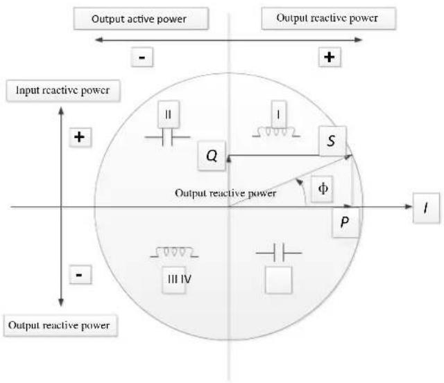
Figure 11 Measurement schematic diagram for energy four quadrants
5. Outline and installation size
able 12 Installation size
| Model | modulus | Outline size(length× width× height) mm | Installation size(din rail) |
| DTSU666 | 4 | 100× 72× 65 | DIN35 din rail |
| DSSU666 | 4 | ||
| DTSU666 series and DSSU666 series three phase electronic energy meter(DIN-Rail) | ZTY0.464.1002 | ||
| Operation manual | Page 13, Total 18 |
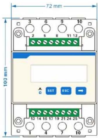
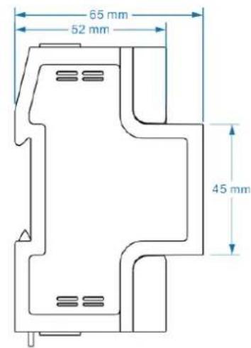
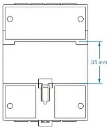
Figure 5 Outline size diagram
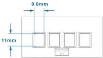
Figure 6 current cable terminal (Conductor Cross-sectional Area Range ≤ 16mm^2 )
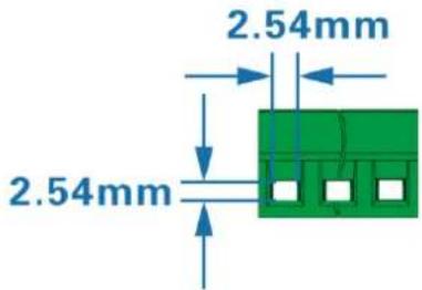
Figure 7 RS485 cable terminal (Conductor Cross-sectional Area Range 0.25-1mm2)
- Installation and operation manual
6.1. Inspection Tips
When unpacking the carton, if the shell has obvious signs caused by severe impact or falling, please contact with the supplier as soon as possible.
After the instrument being removed from the packing box, it should be placed on a flat and safe plane, facing up, not overlaying for more than five layers. If not installed or used in a short time, the electric meter shall be packed and placed to the original packing box for storage.
| DTSU666 series and DSSU666 series three phase electronic energy meter(DIN-Rail) | ZTY0.464.1002 |
| Operation manual | Page 14, Total 18 |
6.2. Installation and tips
6.2.1. Installation and Inspection
If the model No or configuration in the original packing box is not in accordance with the requirement, please contact with the supplier. While, if the inner package or shell has been damaged after removing the instrument from the packing box, please do not install, power on the instrument, please contact with the supplier as soon as possible, instead.
6.2.2. Installation
It requires experienced electrician or professional personnel to install it and you must read this operation manual. During the installation, if the shell has obvious damage or marks caused by violent impact or falling, please do not install it or power on and contact with the supplier as soon as possible.
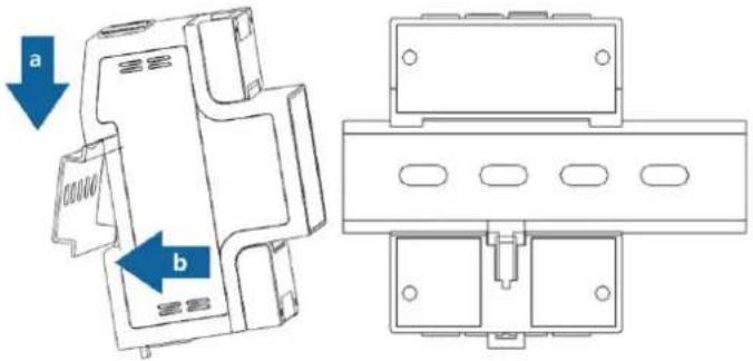
Figure 8
6.3. Typical wiring
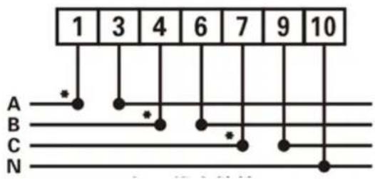
Figure 9 Three phase four wire: direct connect
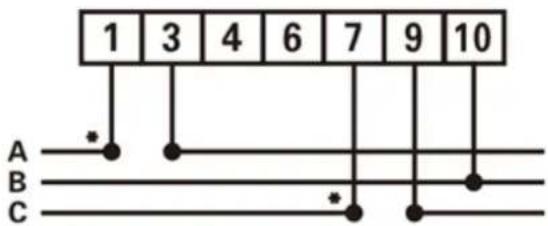
Figure 10 Three phase three wire: direct connect
| DTSU666 series and DSSU666 series three phase electronic energy meter(DIN-Rail) | ZTY0.464.1002 |
| Operation manual | Page 15, Total 18 |
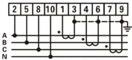
Figure 11 Three phase four wire: Connection throughcurrent transformers
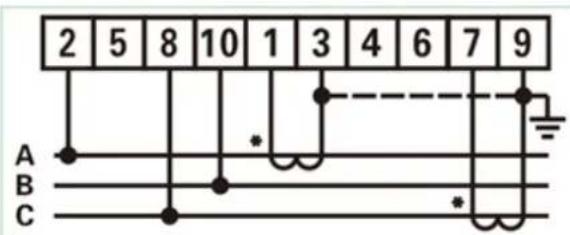
Figure 12 Three phase three wire: Connection through current transformers
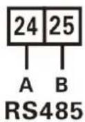
Figure 13 RS485
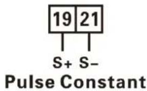
Figure 14 Pulse output
◆ Voltage signal (only for connection via current transformer)
2----UA (Phase A voltage input terminal)
5 ----UB (Phase B voltage input terminal)
8----UC (Phase C voltage input terminal)
10----UN (Phase N voltage input terminal)
◆ Current signal:
1----IA*(Phase A current input terminal)
3----IA (Phase A current output terminal)
4----IB*(Phase B current input terminal)
6----IB (Phase B current output terminal)
7----IC*(Phase C current input terminal)
9----IC(Phase C current output terminal)
◆ RS485 Communication wire
24----A (RS485 Terminal A)
25----B (RS485 Terminal B)
◆ Auxiliary function
19---- Active energy and reactive energy output high terminal
21---- Active energy and reactive energy output low terminal
| DTSU666 series and DSSU666 series three phase electronic energy meter(DIN-Rail) | ZTY0.464.1002 |
| Operation manual | Page 16, Total 18 |
◆ Auxiliary function
19---- Active energy and reactive energy output high terminal
21---- Active energy and reactive energy output low terminal
- Diagnosis, analysis and elimination for common faults
| Fault phenomenon | Reason analysis | Elimination |
| No display when powered on | 1、Incorrect wiring2、Abnormal voltage for the instrument | 1. If it is wrongly connected, please reconnect based on the right wiring mode (see the wiring diagram).2. If the supplied voltage is abnormal, please choose the specified voltage.3. If not the above problems, please contact with the local supplier. |
| Abnormal RS485 communication | 1. RS485 communication cable is opened, short circuit or reversely connected.2. Address, baud rate, data bit and check bit is not in accordance with the host computer.3. The end of RS485 communication cable has not been matched with resistance (when the distance over than 100 meters)4. Not matched with the communication protocol order of the host computer | 1. If there is any problem with the communication cable, please change it.2. Set the address, baud rate, data bit and check bit through buttons and confirm it is the same with the host computer, then set the operation to be “parameter settings”.3. If the communication distance is over than 100 meters, and the communication parameter settings are the same as the host computer, but cannot be communicated, then please lower the baud rate or add a resistance of 120Ω at the start terminal and ending |
| DTSU666 series and DSSU666 series three phase electronic energy meter(DIN-Rail) | ZTY0.464.1002 |
| Operation manual | Page 17, Total 18 |
| terminal. | ||
| Abnormal data for the electrical parameter (voltage, current, power, etc.) | 1. The transformer's ratio hasn't been set, and the instrument displays the secondary side data.2. Wrong wiring. | 1. If setting the transformer ratio, please set the voltage ratio and current ratio based on “parameter setting”2. If wrongly connected, please connect the voltage and current of phase A, B and C to the wiring terminal of the instrument. |
| Abnormal data for the electrical parameter read by communication (voltage, current, power, etc.) | 1. Data read by communication is secondary side data, without transformer ratio.2. Wrong analysis for data frame | 1. Multiply the data read by communication with the voltage ratio and current ratio.2. Analyze the data frame based on the format of the communication protocol, please pay attention to the mode of the big and small end of data. |
8. Transportation & Storage
When transporting and unpacking the products, please confirm they are not severely impacted, transporting and storing based on Transportation, basic environmental conditions and testing methods for instrument and meters of JB/T9329-1999.
The instrument and accessories shall be stored in the dry and ventilated places, to avoid humidity and corrosive gas erosion, with the limited environmental temperature for storage to be -40^ +70^ and relative humidity not exceeding 85%.
9. Maintenance & Service
We guarantee free reparation and change for the multi-meter if found any unconformity with the standard, under circumstance of that the users fully comply with this instructions and complete seal after delivery within 18 months.
| DTSU666 series and DSSU666 series three phase electronic energy meter(DIN-Rail) | ZTY0.464.1002 |
| Operation manual | Page 18, Total 18 |
Dear clients,
Please assist us: when the product life is end, to protect our environment, please recycle the product or components, while for the materials that cannot be recycled, please also deal with it in a proper way. Really appreciate your cooperation and support.
Name of Company: Zhejiang Chint Instrument & Meter Co., Ltd.
Address: Wenzhou Bridge Industrial Zone, Yueqing, Zhejiang, China.
Zip Code: 325603
Telephone: 0577-62877777
Fax: 0577-62891577
Service hotline: 4008177777
Fake Complaint: 0577-62789987
Website: http://www.chint.com
Email: ztyb@chint.com
Date of Issue: June, 2019
No.:ZTY0.464.1002V1


- Manual
- Catalog
- Brief Introduction
- Main application & applicable range
- Product Features
- Product Model
- Temperature range
- Working Principle
- Working Principle
- Principle for the main function module
- Main Technical Performance & Parameters
- limit of error caused by the current augment
- Starting and no-load condition
- Starting
- Test of no-load condition
- Electrical parameters
- Main function
- Displayed function
- Programming function
- Programming function
- Programming operation
- Communication function
- Energy measurement function
- Outline and installation size
- Installation and tips
- Installation and Inspection
- Installation
- Typical wiring
- ◆ Auxiliary function
- Transportation & Storage
- Maintenance & Service
Brand : Deye
Model : CHNTDDSU666
Category : Uncategorized