
AS201 - Meter Owon - Free user manual and instructions
Find the device manual for free AS201 Owon in PDF.


| Product Type | Digital Multimeter |
| Model | AS201 |
| Brand | Owon |
| Display | LCD with backlight |
| Maximum Display Count | 2000 counts |
| DC Voltage Range | 200mV to 600V |
| AC Voltage Range | 200mV to 600V |
| DC Current Range | 200µA to 10A |
| AC Current Range | 200µA to 10A |
| Resistance Range | 200Ω to 20MΩ |
| Capacitance Measurement | Yes, up to 200µF |
| Frequency Measurement | Yes, up to 10MHz |
| Continuity Test | Yes, with audible buzzer |
| Diode Test | Yes |
| Auto Ranging | Yes |
| Data Hold | Yes |
| Safety Rating | CAT II 600V, CAT III 300V |
| Power Supply | 2 x AAA batteries (1.5V) |
| Dimensions (L x W x H) | 140mm x 70mm x 30mm |
| Weight | Approximately 200g (including batteries) |
| Operating Temperature | 0°C to 40°C (32°F to 104°F) |
| Storage Temperature | -10°C to 50°C (14°F to 122°F) |
| Accessories Included | Test leads, manual, batteries |
Frequently Asked Questions - AS201 Owon
User questions about AS201 Owon
0 question about this device. Answer the ones you know or ask your own.
Ask a new question about this device
Download the instructions for your Meter in PDF format for free! Find your manual AS201 - Owon and take your electronic device back in hand. On this page are published all the documents necessary for the use of your device. AS201 by Owon.
USER MANUAL AS201 Owon
July 2019 edition V1.0.1
Copyright © LILLIPUT Company. All rights reserved.
The LILLIPUT's products are under the protection of the patent rights, including ones which have already obtained the patent rights and those which are applied for. The information in this manual will replace all materials published.
The information in this manual was correct at the time of printing. However, LILLIPUT will continue to improve products and reserves the rights to change specification at any time without notice.
owon ^® is the registered trademark of the LILLIPUT Company.
Fujian LILLIPUT Optoelectronics Technology Co., Ltd.
No. 19, Heming Road
Lantian Industrial Zone, Zhangzhou 363005 P.R. China
Tel: +86-596-2130430
Fax: +86-596-2109272
Web: www.owon.com.cn
E-mail: info@owon.com.cn
General Warranty
OWON warrants that the product will be free from defects in materials and workmanship for a period of 3 years from the date of purchase of the product by the original purchaser from the OWON Company. The warranty period for accessories such as probes is 12 months. This warranty only applies to the original purchaser and is not transferable to a third party.
If the product proves defective during the warranty period, OWON will either repair the defective product without charge for parts and labour, or will provide a replacement in exchange for the defective product. Parts, modules and replacement products used by OWON for warranty work may be new or reconditioned like new. All replaced parts, modules and products become the property of OWON.
In order to obtain service under this warranty, the customer must notify OWON of the defect before the expiration of the warranty period. Customer shall be responsible for packaging and shipping the defective product to OWON's designated service centre, a copy of the customers proof of purchase is also required.
This warranty shall not apply to any defect, failure or damage caused by improper use or improper or inadequate maintenance and care. OWON shall not be obligated to furnish service under this warranty a) to repair damage resulting from attempts by personnel other than OWON representatives to install, repair or service the product; b) to repair damage resulting from improper use or connection to incompatible equipment; c) to repair any damage or malfunction caused by the use of non-OWON supplies; or d) to service a product that has been modified or integrated with other products when the effect of such modification or integration increases the time or difficulty of servicing the product.
Please contact the nearest OWON's Sales and Service Offices for services.
For better after-sales service, please visit www.owon.com.cn and register the purchased product online.
Excepting the after-sales services provided in this summary or the applicable warranty statements, OWON will not offer any guarantee for maintenance definitely declared or hinted, including but not limited to the implied guarantee for marketability and special-purpose acceptability. OWON should not take any responsibilities for any indirect, special or consequent damages.
Table of Contents
- General Safety Requirements....1
- Safety Terms and Symbols .... 2
- User Guidebook .... 4
Structure of the Oscilloscope ....4
Front Panel 4
Rear Panel....6
General Inspection....7
Basic Operation....7
Probe Compensation 8
Set the Probe Attenuation Coefficient 9
Use the Probe Safely....9
X-Y Mode....10
-
Troubleshooting....12
-
Technical Specifications .... 13
General Technical Specifications ....14
- Appendix....15
Appendix A: Enclosure....15
Appendix B: General Care and Cleaning....15
1. General Safety Requirements
Before use, please read the following safety precautions to avoid any possible bodily injury and to prevent this product or any other connected products from damage. In order to avoid any contingent danger, ensure this product is only used within the range specified.
Only the qualified technicians can implement the maintenance.
To avoid Fire or Personal Injury:
■ Connect the probe correctly. The grounding end of the probe corresponds to the grounding phase. Please don't connect the grounding end to the positive phase.
■ Use Proper Power Cord. Use only the power cord supplied with the product and certified to use in your country.
■ Connect or Disconnect Correctly. When the probe or test lead is connected to a voltage source, please do not connect and disconnect the probe or test lead at random.
■ Product Grounded. This instrument is grounded through the power cord grounding conductor. To avoid electric shock, the grounding conductor must be grounded. The product must be grounded properly before any connection with its input or output terminal.
When powered by AC power, it is not allowed to measure AC power source directly, because the testing ground and power cord ground conductor are connected together, otherwise, it will cause short circuit.
■ Check all Terminal Ratings. To avoid fire or shock hazard, check all ratings and markers of this product. Refer to the user's manual for more information about ratings before connecting to the instrument.
■ Do not operate without covers. Do not operate the instrument with covers or panels removed.
■ Use Proper Fuse. Use only the specified type and rating fuse for this instrument.
- Avoid exposed circuit. Do not touch exposed junctions and components when the instrument is powered.
- Do not operate if in any doubt. If you suspect damage occurs to the instrument, have it inspected by qualified service personnel before further operations.
■ Use your Oscilloscope in a well-ventilated area. Make sure the instrument installed with proper ventilation, refer to the user manual for more details.
■ Do not operate in wet conditions.
■ Do not operate in an explosive atmosphere.
- Keep product surfaces clean and dry.
2. Safety Terms and Symbols
Safety Terms
Terms in this manual. The following terms may appear in this manual:

Warning: Warning indicates the conditions or practices that could result in injury or loss of life.

Caution: Caution indicates the conditions or practices that could result in damage to this product or other property.
Terms on the product. The following terms may appear on this product:
Danger: It indicates an injury or hazard may immediately happen.
Warning: It indicates an injury or hazard may be accessible potentially.
Caution: It indicates a potential damage to the instrument or other property might occur.
Safety Symbols
Symbols on the product. The following symbol may appear on the product:

Hazardous Voltage

Refer to Manual

Protective Earth Terminal

Chassis Ground

Test Ground
To avoid body damage and prevent product and connected equipment damage, carefully read the following safety information before using the test tool. This product can only be used in the specified applications.

Warning:
In X-Y mode, the X Input and Y Input of the oscilloscope are not electrically isolated. The channels should adopt a common ground during measuring. To prevent short circuits, the 2 probe grounds must not be connected to 2 different non-isolated DC levels.
The diagram of the oscilloscope ground wire connection:
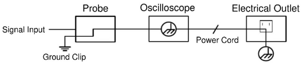
flowchart
graph LR
    A["Signal Input"] --> B["Probe"]
    B --> C["Oscilloscope"]
    C --> D["Power Cord"]
    D --> E["Electrical Outlet"]
    F["Ground Clip"] --> B

Warning:
To avoid fire or electrical shock, when the oscilloscope input signal connected is more than 42V peak (30Vrms) or on circuits of more than 4800VA, please take note of below items:
- Only use accessory insulated voltage probes and test lead.
- Check the accessories such as probe before use and replace it if there are any damages.
- Remove probes, test leads and other accessories immediately after use.
- Do not apply input voltages above the rating of the instrument because the probe tip voltage will directly transmit to the oscilloscope. Use with caution when the probe is set as 1:1.
- Do not use exposed metal BNC or banana plug connectors.
- Do not insert metal objects into connectors.
3. User Guidebook
Structure of the Oscilloscope
This chapter makes a simple description of the operation and function of the front panel of the oscilloscope, enabling you to be familiar with the use of the oscilloscope in the shortest time.
Front Panel
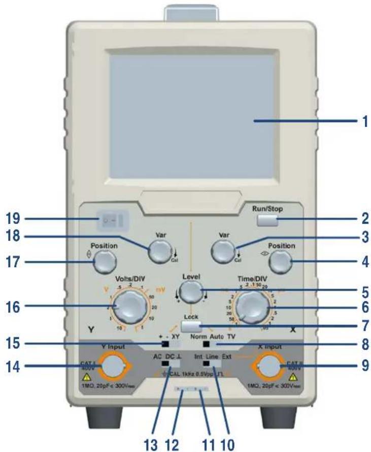
Figure 3-1 Front panel
| No. | Name | Description |
| 1 | Display screen | Display the trace. |
| 2 | Run/Stop | Enable or disable sampling on input signals. |
| 3 | Var (right side) | Provides continuously variable sweep rate. Turn clockwise until the waveform does not change is the calibration position. |
| 4 | ◀▶Position | Horizontal positioning control of trace on the screen. |
| 5 Level | Control signal trigger to sweep at certain level.Towards "": The triggering level moves downward on the display waveform.Towards "+": The triggering level moves upward on the display waveform. | |
| 6 | Time/DIV | Select the sweep rate. |
| 7 | Lock | When the Lock button is pressed down, the triggering level is automatically maintained at optimum value irrespective of the signal amplitude, requiring no manual adjustment of triggering level. |
| 8 | Norm/Auto/TV | Select the desired trigger mode.Norm: No trace on screen if no signal. Trace is only generated when adequate trigger signal is present.Auto: a single trace shown on screen even no signal. Automatically reverts to triggered sweep operation when adequate triggered signal is present.Needs to adjust the Level.TV: Used to show TV signals. |
| 9 | X Input | When switching to XY mode, it's X input terminal.When switching the trigger source to Ext, it's external trigger input terminal. |
| 10 | Int/Line/Ext | Switch to select the Trigger Source.Int: Select internal signal as trigger source signal.Line: Select AC power line as trigger signal.Ext: The external signal applied through X Input terminal is used for the external triggering source signal. |
| 11 | CAL signal | Provide calibration square wave for 0.5Vpp range, frequency=1kHz. Used for adjusting probe compensation and adjusting the vertical & horizontal sensitivity. |
| 12 | CAL ground | Ground wire connector of the calibration signal. |
| 13 | AC/DC/⊥ | Switch for selecting coupling mode.AC: Block the DC component of the input signal.DC: Pass both AC and DC components of the input signal.⊥ (GND): Disconnect the input signal. |
| 14 | Y Input | Vertical input terminal. |
3.User Guidebook
| 15 | +/-/XY | +: Trigger on rising slope. Triggering occurs when the triggering signal crosses the triggering level in positive-going direction. -: Trigger on falling slope. Triggering occurs when the triggering signal crosses the triggering level in negative-going direction. XY: This position is used when using the instrument as an X-Y oscilloscope. |
| 16 | Volts/DIV | Adjusting sensitivity of vertical system. |
| 17 | Position | Control vertical position of trace on the screen. |
| 18 | Var (left side) | Continuously adjusting the sensitivity of vertical system. Turn clockwise until the waveform does not change is the calibration position. |
| 19 | Power switch | Main power on/off. |
Rear Panel
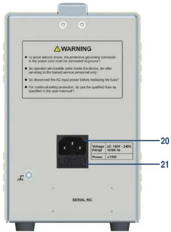
Figure 3-2 Rear Panel
| No. | Name | Description |
| 20 | AC Power input connector | Connect the supplied AC power cord to this connector. |
| 21 | Fuse holder | Fuse rating is 1A, T class, 250 V. |
General Inspection
After you get a new oscilloscope, it is recommended that you should make a check on the instrument according to the following steps:
1. Check whether there is any damage caused by transportation.
If it is found that the packaging carton or the foamed plastic protection cushion has suffered serious damage, do not throw it away first till the complete device and its accessories succeed in the electrical and mechanical property tests.
2. Check the Accessories
The supplied accessories have been already described in the "Appendix A: Enclosure" of this Manual. You can check whether there is any loss of accessories with reference to this description. If it is found that there is any accessory lost or damaged, please get in touch with the distributor of OWON responsible for this service or the OWON's local offices.
3. Check the Complete Instrument
If it is found that there is damage to the appearance of the instrument, or the instrument can not work normally, or fails in the performance test, please get in touch with the OWON's distributor responsible for this business or the OWON's local offices. If there is damage to the instrument caused by the transportation, please keep the package. With the transportation department or the OWON's distributor responsible for this business informed about it, a repairing or replacement of the instrument will be arranged by the OWON.
Basic Operation
- Set the switches and controls on the front panel as shown below.
Position for control switches
| Item | No. in Figure 3-1 Front panel | Setting |
| Power switch | 19 | ○ pressed down |
| Volts/DIV | 16 | 0.1 V |
| Norm/Auto/TV | 8 | Auto |
| Time/DIV | 6 | 0.5 ms |
| +/-/XY | 15 | + |
| Int/Line/Ext | 10 | Int |
| AC/DC/⊥ | 13 | ⊥ |
| Lock | 7 | Pressed down |
- Connect the power cord to the AC line outlet. Press the power switch ☐ — on the front panel to power on, the screen will light up. A few seconds later, a trace will appear on the screen.
- Align the trace with the horizontal center line of the graticule by adjusting the Position knob.
- Connect the probe to the Y Input terminal and apply the 0.5 Vpp CALIBRATOR signal to be probe tip.
- Set the AC/DC/⊥ switch to the AC state. A square waveform will be displayed on the screen.
- For signal viewing, set the Volts/DIV switch and Time/DIV switch in appropriate positions so that signal waveform is displayed clearly.
- Adjust the Position and Position controls in appropriate positions so that the displayed waveform is aligned with the graticule and voltage and period can be read conveniently.
Probe Compensation
When connect the probe with the input channel for the first time, make this adjustment to match the probe with the input channel. The probe which is not compensated or presents a compensation deviation will result in the measuring error or mistake. For adjusting the probe compensation, please carry out the following steps:
- Set the switch in the probe to 10X. (see "Set the Probe Attenuation Coefficient" on P9).
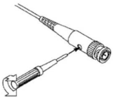
- Connect the probe BNC connector to the Y Input terminal. Connect the probe tip to the calibration signal on the front panel (see 11 of Figure 3-1 Front panel). Connect the reference wire clamp to the ground wire connector of the calibration signal (see 12 of Figure 3-1 Front panel).
- Check the displayed waveforms and regulate the probe till a correct compensation is achieved (see Figure 3-3 and Figure 3-4).
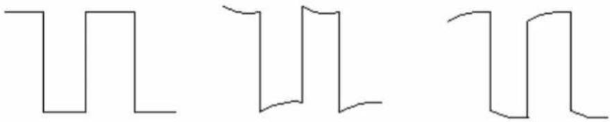
natural_image
Three identical abstract line patterns with no text, numbers, or symbolsCompensated correctly
Overcompensated
Under compensated
Figure 3-3 Displayed Waveforms of the Probe Compensation
natural_image
Technical line drawing of two mechanical components with no visible text or symbolsFigure 3-4 Adjust Probe
Set the Probe Attenuation Coefficient
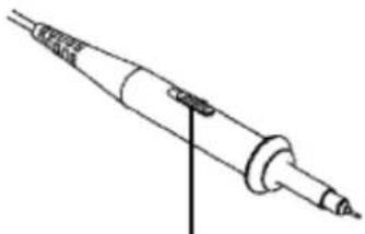
The probe has several attenuation coefficients, which will influence the vertical scale factor of the oscilloscope.
The set values of the probe switch are 1X and 10X (see Figure 3-5).
natural_image
Line drawing of a soldering iron with a vertical pin (no text or symbols)Figure 3-5 Attenuation Switch

Caution:
When the attenuation switch is set to 1X, the probe will limit the bandwidth of the oscilloscope in 5MHz or 6MHz. To use the full bandwidth of the oscilloscope, the switch must be set to 10X.
Use the Probe Safely
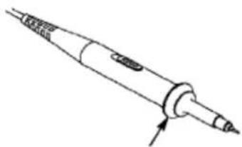
The safety guard ring around the probe body protects your finger against any electric shock, shown as Figure 3-6.
natural_image
Line drawing of a soldering iron with a pointed tip and threaded shaft (no text or symbols)Figure 3-6 Finger Guard

Warning:
To avoid electric shock, always keep your finger behind the safety guard ring of the probe during the operation.
To protect you from suffering from the electric shock, do not touch any metal part of the probe tip when it is connected to the power supply.
Before making any measurements, always connect the probe to the instrument and connect the ground terminal to the earth.
X-Y Mode
Examine the Phase Difference between Signals of two Channels
X-Y mode is a very useful when examining the Phase difference of two signals.
- Set the +/-/XY control on the front panel to the XY position.
- Set the switch in the probe to 1X or 10X, depend on your need (see "Set the Probe Attenuation Coefficient" on P9).
- Connect the probe of Y Input to the Y-axis signal (vertical axis signal). Connect the probe of X Input to the X-axis signal (horizontal axis signal).
- Turn the Volts/DIV knob to set the vertical scale of Y-axis signal. The vertical scale of X-axis signal is fixed as 0.5V/DIV.
- The vertical position is adjusted using the Position knob. The horizontal position is adjusted using the Position knob.
- With the elliptical oscillogram method adopted, observe and calculate the phase difference (see Figure 3-7).
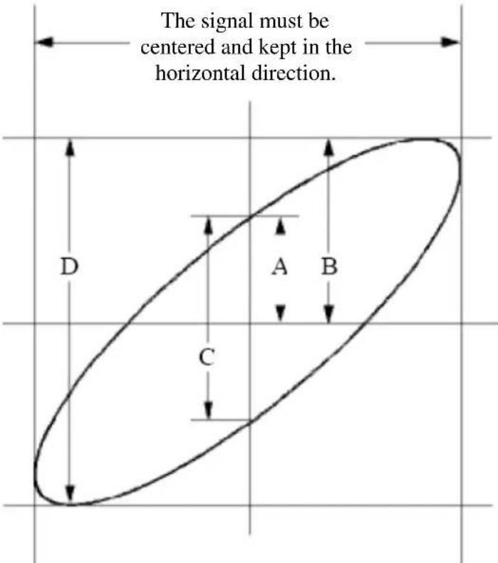
Figure 3-7 Lissajous Graph
Based on the expression (q) = A / B or C / D , thereinto, q is the phase difference angle, and the definitions of A, B, C , and D are shown as the graph above. As a result, the phase difference angle can be obtained, namely, q = ± (A / B) or ± (C / D) . If the principal axis of the ellipse is in the I and III quadrants, the determined phase difference angel should be in the I and IV quadrants, that is, in the range of (0 - / 2) or (3 / 2 - 2) . If the principal axis of the ellipse is in the II and IV quadrants, the determined phase difference angle is in the II and III quadrants, that is, within the range of ( / 2 - ) or ( - 3 / 2) .
4. Troubleshooting
1. Oscilloscope is powered on but no Display.
- Check whether the power connection is connected properly.
- Check whether the fuse which is beside the AC power input jack is blew (the cover can be pried open with a straight screwdriver).
- Restart the instrument after completing the checks above.
- If the problem persists, please contact OWON and we will be under your service.
2. After acquiring the signal, the waveform of the signal is not displayed in the screen.
- Check whether the probe is properly connected to the signal connecting wire.
- Check whether the signal connecting wire is correctly connected to the BNC (namely, the channel connector).
- Check whether the probe is properly connected with the object to be measured.
- Check whether there is any signal generated from the object to be measured (the trouble can be shot by the connection of the channel from which there is a signal generated with the channel in fault).
● Make the signal acquisition operation again.
3. The measured voltage amplitude value is 10 times or 1/10 of the actual value.
Look at the attenuation ration of the probe (see "Set the Probe Attenuation Coefficient" on P9).
4. There is a waveform displayed, but it is not stable.
- Check whether the trigger source (Int/Line/Ext controls on the front panel) is in conformity with the signal channel used in the practical application.
- Press down the Lock button on the front panel.
5. Technical Specifications
Unless otherwise specified, the technical specifications applied are for single-channel series only, and Probes attenuation set as 10X. Only if the oscilloscope fulfills the following condition at first, these specification standards can be reached.
■ This instrument should run for at least 30 minutes continuously under the specified operating temperature.
All specification standards can be fulfilled, except one(s) marked with the word "Typical".
| Performance Characteristics | Instruction | |||
| Bandwidth | AS101 | DC | 0 – 10 MHz | |
| AC | 10 Hz – 10 MHz | |||
| AS201 | DC | 0 – 20 MHz | ||
| AC | 10 Hz – 20 MHz | |||
| Channel Q'nty | 1 | |||
| Acquisition | Run/Stop | supported | ||
| Sampling Rate | 100M Sa/s | |||
| Input | Input Coupling | DC, AC, and ground | ||
| Input Impedance | 1 MΩ ± 2%, in parallel with 20 pF±5 pF | |||
| Max. Input Voltage | 400V (DC+AC, PK - PK) | |||
| Horizontal System | Sampling Rate Range | 0.5 Sa/s - 100 MSa/s | ||
| Interpolation | sin(x)/x | |||
| Scanning Speed (s/DIV) | 0.05μs/DIV - 0.1s/DIV, step by 1 - 2 - 5 | |||
| Sampling Rate / Relay Time Accuracy | ±100 ppm | |||
| Trimming Ratio | ≥ 2.5:1 | |||
| Vertical system | Sensitivity | 5 mV/DIV - 10 V/DIV | ||
| Displacement | ±10 DIV | |||
| Analog Bandwidth | AS101 | 10 MHz | ||
| AS201 | 20 MHz | |||
| Low Frequency | ≥ 10 Hz (at input, AC coupling, -3 dB) | |||
| Rise Time (at input, typical) | ≤ 30 ns | |||
| Trimming Ratio | ≥ 2.5:1 | |||
X-Y Mode
| Sensitivity | X: 0.5V/DIV, Y: 0.1V/DIV - 1V/DIV |
| Bandwidth (-3dB) | DC: 0 - 1MHz, AC: 10Hz - 1MHz |
Trigger
| Trigger Level Range | Internal | ±4 DIV from the screen center |
| Trigger Level Accuracy (typical) | Internal, External | ±0.3 DIV |
- Technical Specifications
| Trigger Lock | supported | |
| Edge Trigger | Slope | rising, falling |
| Video Trigger Modulation | supported standard: NTSC, PAL and SECAM broadcast systems | |
| Ext. Trigger Input Impedance | 1 MΩ ± 2%, in parallel with 20 pF±5 pF | |
| Ext. Trigger Max. Input Voltage | 400 Vpp | |
| Trigger Source | Int, Line, Ext | |
| Trigger Mode | Norm, Auto, and TV | |
Output of the Probe Compensator
| Output Voltage (typical) | square, 0.5 Vpp ± 2% |
| Frequency (typical) | square wave of 1 kHz (±1%) |
General Technical Specifications
Display
| Display Type | 3.7" LCD, TFT screen |
| Display Resolution | 320 (horizontal) x 240 (vertical) pixels |
| Display Color | 65536 colors |
| Power | |
| Mains Voltage | 100 - 240 VACRMS, 50/60 Hz, CAT II |
| Power Consumption | < 15 W |
| Fuse | 1A, T class, 250 V |
| Environment | |
| Temperature | working temperature: (0 °C) - (+40 °C) |
| storage: (-20 °C) - (+60 °C) | |
| Relative Humidity | ≤ 90% |
| Height | operating: 3,000 m |
| non-operating: 15,000 m | |
| Cooling Method | natural cooling |
| Mechanical Specifications | |
| Dimension (D/H/W) | 288 mm x 195 mm x 117 mm |
| Weight | Approx. 1.8 kg |
Interval Period of Adjustment:
One year is recommended for the calibration interval period.
6. Appendix
Appendix A: Enclosure
(The accessories subject to final delivery.)
Standard Accessories:
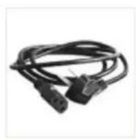
natural_image
Coiled black cable with two connectors, no visible text or symbolsPower Cord

Quick Guide
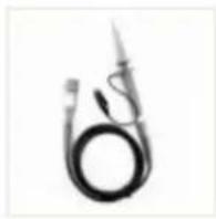
Probe
Spare Fuse
Probe Adjust
Appendix B: General Care and Cleaning
General Care
Do not store or leave the instrument where the display will be exposed to direct sunlight for long periods of time.
Caution: To avoid any damage to the instrument or probe, do not exposed it to any sprays, liquids, or solvents.
Cleaning
Inspect the instrument and probes as often as operating conditions require. To clean the instrument exterior, perform the following steps:
- Wipe the dust from the instrument and probe surface with a soft cloth. Do not make any scuffing on the transparent LCD protection screen when clean the LCD screen.
- Disconnect power before cleaning your Oscilloscope. Clean the instrument with a wet soft cloth not dripping water. It is recommended to scrub with soft detergent or fresh water. To avoid damage to the instrument or probe, do not use any corrosive chemical cleaning agent.

Warning: Before power on again for operation, it is required to confirm that the instrument has already been dried completely, avoiding any electrical short circuit or bodily injury resulting from the moisture.


- July 2019 edition V1.0.1
- General Warranty
- Table of Contents
- General Safety Requirements
- Safety Terms and Symbols
- Safety Terms
- Safety Symbols
- Warning:
- User Guidebook
- Structure of the Oscilloscope
- 3.User Guidebook
- Rear Panel
- General Inspection
- Check whether there is any damage caused by transportation.
- Check the Accessories
- Check the Complete Instrument
- Basic Operation
- Probe Compensation
- Set the Probe Attenuation Coefficient
- Caution:
- Use the Probe Safely
- X-Y Mode
- Examine the Phase Difference between Signals of two Channels
- Troubleshooting
- Oscilloscope is powered on but no Display.
- After acquiring the signal, the waveform of the signal is not displayed in the screen.
- The measured voltage amplitude value is 10 times or 1/10 of the actual value.
- There is a waveform displayed, but it is not stable.
- Technical Specifications
- General Technical Specifications
- Interval Period of Adjustment:
- Appendix
- Appendix A: Enclosure
- Standard Accessories:
- Appendix B: General Care and Cleaning
- General Care
- Cleaning
Brand : Owon
Model : AS201
Category : Meter