
AP-1 - Remote control SONY - Free user manual and instructions
Find the device manual for free AP-1 SONY in PDF.


| Product Type | Remote Control |
| Brand | Sony |
| Model | AP-1 |
| Dimensions (Approx.) | 15 x 5 x 2 cm |
| Weight (Approx.) | 100 g |
| Power Source | 2 x AAA batteries |
| Transmission Type | Infrared (IR) |
| Operating Range | Up to 8 meters |
| Key Functions | Power, Volume, Channel, Menu, Directional Pad, Input Select, Mute, Number Pad |
| Compatibility | Sony TVs and compatible devices |
| Battery Life | Approx. 6 months with normal use |
| Care Instructions | Wipe with a dry, soft cloth. Do not use liquids. |
| Safety Precautions | Keep away from water and heat sources. |
| Spare Parts | Replacement batteries (AAA) |
| Repairability | Not user-serviceable. Contact Sony support. |
| Warranty | 1 year limited warranty |
Frequently Asked Questions - AP-1 SONY
User questions about AP-1 SONY
0 question about this device. Answer the ones you know or ask your own.
Ask a new question about this device
Download the instructions for your Remote control in PDF format for free! Find your manual AP-1 - SONY and take your electronic device back in hand. On this page are published all the documents necessary for the use of your device. AP-1 by SONY.
USER MANUAL AP-1 SONY
Turn off the power immediately and extinguish the fire.
Meaning of Warning Labels
Plain Filter Label
(External View)
| No. | 信号 I/O | 仕様 | |
| 1 | SIN IN VFD_I/F | ||
| 2 | SBUSY OUT | VFD_I/F | |
| 3 | XRESET IN | VFD_I/F | |
| 4 | RE_B OUT | ||
| 5 | RE_A OUT | ||
| 6 | IIC_DATA | IN/OUT | TTL レベル |
| 7 | IIC_CLK IN | TTL | レベル |
| 8 | POWER | IN | |
| 9 | GND | - | |
| 10 | NC | ||
| 11 | AUX1 | OUT | OPEN or +5V : NormalGND : Active |
| 12 | AUX2 | OUT | OPEN or +5V : NormalGND : Active |
| 13 | AUX3 | OUT | OPEN or +5V : NormalGND : Active |
| 14 | NC | ||
English
For the customers in the U.S.A.
This equipment has been tested and found to comply with the limits for a Class B digital device, pursuant to Part 15 of the FCC Rules. These limits are designed to provide reasonable protection against harmful interference in a residential installation. This equipment generates, uses, and can radiate radio frequency energy and, if not installed and used in accordance with the instructions, may cause harmful interference to radio communications. However, there is no guarantee that interference will not occur in a particular installation. If this equipment does cause harmful interference to radio or television reception, which can be determined by turning the equipment off and on, the user is encouraged to try to correct the interference by one or more of the following measures:
—Reorient or relocate the receiving antenna. —Increase the separation between the equipment and receiver. —Connect the equipment into an outlet on a circuit different from that to which the receiver is connected. —Consult the dealer or an experienced radio/TV technician for help.
You are cautioned that any changes or modifications not expressly approved in this manual could void your authority to operate this equipment.
All interface cables used to connect peripherals must be shielded in order to comply with the limits for a digital device pursuant to Subpart B of Part 15 of FCC Rules.
This device complies with Part 15 of the FCC Rules. Operation is subject to the following two conditions: (1) this device may not cause harmful interference, and (2) this device must accept any interference received, including interference that may cause undesired operation.
For the customers in Canada
This Class B digital apparatus complies with Canadian ICES-003.
For the customers in Europe
This product with the CE marking complies with the EMC Directive issued by the Commission of the European Community. Compliance with this directive implies conformity to the following European standards:
• EN55103-1: Electromagnetic Interference (Emission) • EN55103-2: Electromagnetic Susceptibility (Immunity) This product is intended for use in the following Electromagnetic Environments: E1 (residential), E2 (commercial and light industrial), E3 (urban outdoors), E4 (controlled EMC environment, e.g., TV studio).
The manufacturer of this product is Sony Corporation, 1-7-1 Konan, Minato-ku, Tokyo, Japan.
The Authorized Representative for EMC and product safety is Sony Deutschland GmbH, Hedelfinger Strasse 61, 70327 Stuttgart, Germany.
Locations and Functions of Parts.... 15
Attaching to the SRW-9000 ....17
Pasting the Blank Filter Label ....18
Specifications ....19
Connector Pin Assignments ....20
Features
The AP-1 is an assistant panel that can be connected to a camera or camcorder to provide convenient access to the same operations as the subdisplay on the right side of the camera main unit.
Connectable cameras and camcorder
Locations and Functions of Parts

① Connection cable
This cable (supplied) is for connections between the CAMERA connector of this panel and the assistant panel connector of the camera.
Refer to the operation manual of the camera for the location of the camera's assistant panel connector.
②CAMERA connector
Connect the supplied connection cable.
③LOCK switch
Locks the operating switches of the AP-1.
④VF (viewfinder) MENU/DISPLAY button
Switches the information displayed in the subdisplay and in the viewfinder connected to the camera main unit.
⑤ Assignable buttons 1 to 3
These buttons execute the functions assigned to assignable buttons 1 to 3 on the camera.
Refer to the operation manual of the camera for more information about assigning functions to the assignable buttons.
⑥ CANCEL/STATUS button
Cancels menu settings made in the subdisplay and in the viewfinder connected to the camera, or returns the display to a previous state.
When no menu is displayed in the viewfinder, you can press this button to display information about the status of the camera main unit.
Refer to the operation manual of the camera for more information about the status information that appears.
⑦RUN button and indicator
Starts and stops recording by the recorder or camcorder attached to the camera.
The indicator lights during recording.
Note
This indicator also flashes to indicate a camera main unit warning.
Refer to the operation manual of the camera for more information about warnings.
⑧ Assignable 4/AUTO BLK BAL (auto black balance) switch
Push the switch down to the AUTO BLK BAL side to start automatic black balance adjustment.
Push the switch up to the 4 side to execute the function assigned to assignable switch 4.
⑨ PAGE button
In subdisplay screens, switches to the next page or confirms settings.
⑩ SET button
In subdisplay screens, hold this button down for one second or longer to enter settings modification mode.
This button also returns to the previous subdisplay page.
⑪ Subdisplay
Displays the menus and settings of the camera main unit. The same information appears in the subdisplay of the camera main unit.
⑫ MENU SEL (selection)/ENTER dial
In subdisplay and viewfinder screens, selects menu items and confirms settings.
Attaching to the SRW-9000
After attaching the supplied hook base to the SRW-9000, attach the AP-1 to the hook base.
Note
The hook base cannot be attached to equipment other than the SRW-9000.
1 Remove the microphone holder attachment screws, and use the screws to attach the hook base.
Microphone holder attachment screws

2 Hang the reverse side of the AP-1 on the hook base.

Pasting the Blank Filter Label
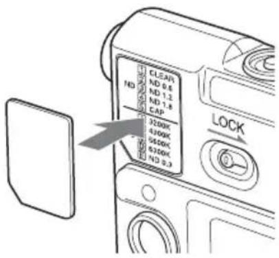
Some cameras, such as the F35, have filter configurations that differ from the indications on the filter label of the AP-1. If you are using such a camera, you can paste the supplied blank filter label over the AP-1's original filter label.
Filter label of the AP-1

Proceed as follows to paste the blank filter label.
1 Peel off the blank filter label from its protective sheet.

Blank filter label
2 Paste the blank filter label that you peeled off in step 1, and then paste it over the original label.
Specifications
Power requirements
DC 6 V
Power consumption
1 W
Operating temperature
0 °C (32 °F) to +40 °C (104 °F)
Storage temperature
-20 °C (-4 °F) to +60 °C (+140 °F)
Mass 0.26 kg (9 oz) (main unit only)
Dimensions (Unit: mm (inches))

Supplied accessories
Connection cable (1)
Blank filter label (1)
Operation manual (1)
Hook base (1)
Microphone holder attachment screws (2)
Design and specifications are subject to change without notice.
Note
Always verify that the unit is operating properly before use. SONY WILL NOT BE LIABLE FOR DAMAGES OF ANY KIND INCLUDING, BUT NOT LIMITED TO, COMPENSATION OR REIMBURSEMENT ON ACCOUNT OF THE LOSS OF PRESENT OR PROSPECTIVE PROFITS DUE TO FAILURE OF THIS UNIT, EITHER DURING THE WARRANTY PERIOD OR AFTER EXPIRATION OF THE WARRANTY, OR FOR ANY OTHER REASON WHATSOEVER.
Connector Pin Assignments
CAMERA (14-pin, female)

(External View)
| No. | Signal I/O | Specifications | |
| 1 | SIN IN VFD_I/F | ||
| 2 | SBUSY OUT | VFD_I/F | |
| 3 | XRESET IN VFD_I/F | ||
| 4 | R E | _ B | O U |
| 5 | R E | _ A | O U |
| 6 | IIC_DATA IN/OUT TTL level | ||
| 7 | IIC_CLK IN TTL level | ||
| 8 | P O | W E | R I N |
| 9 | G N | D - | |
| 10 | NC | ||
| 11 | AUX1 | OUT OP | EN or +5V: Normal GND: Active |
| 12 | AUX2 | OUT OP | EN or +5V: Normal GND: Active |
| 13 | AUX3 | OUT OP | EN or +5V: Normal GND: Active |
| 14 | NC | ||
The material contained in this manual consists of information that is the property of Sony Corporation and is intended solely for use by the purchasers of the equipment described in this manual.
Sony Corporation expressly prohibits the duplication of any portion of this manual or the use thereof for any purpose other than the operation or maintenance of the equipment described in this manual without the express written permission of Sony Corporation.
For Customer in China
Printed on recycled paper.
Printed in Japan
2009.09 08
© 2009
- MEANING OF WARNING LABELS
- ENGLISH
- FOR THE CUSTOMERS IN THE U.S.A
- FOR THE CUSTOMERS IN CANADA
- FOR THE CUSTOMERS IN EUROPE
- FEATURES
- CONNECTABLE CAMERAS AND CAMCORDER
- LOCATIONS AND FUNCTIONS OF PARTS
- ① CONNECTION CABLE
- ②CAMERA CONNECTOR
- ③LOCK SWITCH
- ④VF (VIEWFINDER) MENU/DISPLAY BUTTON
- ⑤ ASSIGNABLE BUTTONS 1 TO
- ⑥ CANCEL/STATUS BUTTON
- ⑦RUN BUTTON AND INDICATOR
- NOTE
- ⑧ ASSIGNABLE 4/AUTO BLK BAL (AUTO BLACK BALANCE) SWITCH
- ⑨ PAGE BUTTON
- ⑩ SET BUTTON
- ⑪ SUBDISPLAY
- ⑫ MENU SEL (SELECTION)/ENTER DIAL
- ATTACHING TO THE SRW
- PASTING THE BLANK FILTER LABEL
- SPECIFICATIONS
- CONNECTOR PIN ASSIGNMENTS
- FOR CUSTOMER IN CHINA
Brand : SONY
Model : AP-1
Category : Remote control