
9233-010 - Grinder Hazet - Free user manual and instructions
Find the device manual for free 9233-010 Hazet in PDF.

| Product Type | Angle Grinder |
| Brand | Hazet |
| Model | 9233-010 |
| Disc Diameter | 125 mm (5 in) |
| Power Supply | Corded electric, 230 V / 50 Hz |
| Rated Power | 1100 W |
| No-Load Speed | 11000 rpm |
| Dimensions (L x W x H) | 360 x 120 x 110 mm |
| Weight | 2.3 kg |
| Spindle Thread | M14 |
| Main Functions | Grinding, cutting, brushing, polishing |
| Safety Features | Spindle lock, guard, safety switch, anti-restart |
| Vibration Control | Side handle with vibration damping |
| Maintenance | Clean air vents regularly, replace carbon brushes when worn |
| Spare Parts | Carbon brushes, guard, side handle, switch, armature |
| Repairability | Modular design, spare parts available from Hazet |
| Certification | CE, EAC |
| Package Contents | Grinder, side handle, guard, wrench, grinding disc |
Frequently Asked Questions - 9233-010 Hazet
User questions about 9233-010 Hazet
0 question about this device. Answer the ones you know or ask your own.
Ask a new question about this device
Download the instructions for your Grinder in PDF format for free! Find your manual 9233-010 - Hazet and take your electronic device back in hand. On this page are published all the documents necessary for the use of your device. 9233-010 by Hazet.
USER MANUAL 9233-010 Hazet
HIGHEST TECHNOLOGY IN TOOL MANUFACTURE SINCE 1868
NEJVYŠŠÍ TECHNOLOGIE PŘI VÝROBĚ NÁŘADÍ OD ROKU 1868
NAJVEĆA KVALITETA U PROIZVODNJI ALATA JOŠ OD 1868

9233-7

Betriebsanleitung
Operating Instructions
Cordless right-angle grinder
Návod k obsluze
natural_image
Exterior view of a HAZET 9233-7 angle grinder with blue and black casing (no signage or text beyond branding)CE

Inhaltsverzeichnis
1 For your information 23
2 For your safety 24
3 Design and Function...... 29
4 Maintenance and care ..... 41

Obsah
natural_image
Technical line drawing of a mechanical component with directional arrows indicating movement (no text or symbols)Vor Inbetriebnahme:
natural_image
Technical line drawing of a mechanical device with no visible text or symbols

Vorsicht!
natural_image
Mechanical assembly diagram showing a valve mechanism with a numbered component (1) and no visible text or symbols.
natural_image
Mechanical assembly diagram showing a robotic arm with labeled component (no text or symbols present)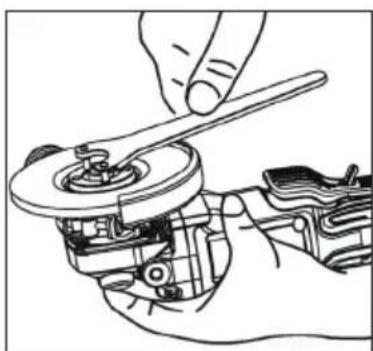
natural_image
Line drawing of a hand using a wrench to adjust a mechanical component (no text or symbols present)
Vorsicht!
Elektrische Bremse
natural_image
Illustration of a hand using a tool to adjust or install a mechanical component (no text or symbols visible)natural_image
Technical line drawing of a mechanical device with internal components (no text or symbols)
Anmerkung:
natural_image
Illustration of hands using a tool to adjust or install a device (no text or symbols visible)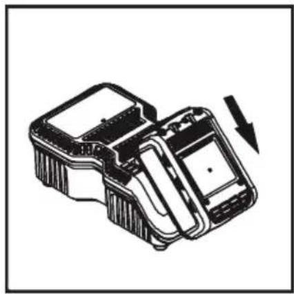
natural_image
Technical line drawing of a mechanical device with a downward arrow indicating motion (no text or symbols)
- Please make sure that the user of this tool carefully reads these operating instructions and fully understands all information given before it is used.
- These operating instructions contain important advice that is necessary for the safe and trouble-free operation of your HAZET tool.
- For intended use of the tool, it is essential that all safety precautions and other information in these operating instructions are adhered to.
- For this reason, always keep these operating instructions together with your HAZET tool.
- This tool has been designed exclusively for specific applications. HAZET emphasises that any modification to the tool and/or use in a way that does not correspond to its intended application is strictly forbidden.
- HAZET will not be liable for any injuries to persons or damage to property originating from improper or inappropriate application, misuse of the tool or a disregard of the safety instructions.
- Furthermore, the general safety regulations and regulations for the prevention of accidents in the application range of this tool must be observed and respected.
2. Explanation of symbols
ATTENTION: Pay strict attention to these symbols!

Read the operating instructions!
The owner is obliged to observe the operating instructions and instruct all users of this tool according to the operating instructions.

NOTE!
This symbol indicates advice that is helpful when using the tool.

WARNING!
This symbol indicates important specifications, dangerous conditions, safety risks and safety advice.

CAUTION!
This symbol marks advice which if disregarded results in damage, malfunction and/or functional failure of the tool.

QUALIFIED PERSONNEL!
The tool may be used by qualified personnel only. Handling by non-qualified people may lead to injuries to persons or damage to the tool or the workpiece.

Electrical energy may cause serious injuries!
Always wear personal protective equipment!

1. Owner's liability
- The tool was developed and manufactured according to the technical norms and standards valid and recognised at the time and is considered to be operationally reliable. Nevertheless, the tool may present a danger when it is not used as intended or in an inappropriate way by non-qualified personnel. Please make sure that any person using this tool or carrying out maintenance work carefully reads and fully understands these operating instructions before using the tool.
- Any modification of the tool is strictly forbidden.
- All safety, warning and operating instructions on the tool must be kept legible at all times. All damaged labels or stickers must be replaced immediately.
- All specified set values or ranges must be observed.
• Always keep the operating instructions close to the tool. - The tool must only be used if it is in good working condition.
- All safety equipment must always be within easy reach and should be checked regularly.

2. Intendeduse
Operational reliability is only guaranteed if the tool is used as intended in accordance with the information in the operating instructions. In addition to the safety advice in these operating instructions, the general safety regulations, regulations for the prevention of accidents and regulations for environmental protection valid for this tool's application range must be observed and respected.
Use and maintenance of the tool must always comply with relevant local and national regulations.
- The HAZET cordless right-angle grinder is for grinding/separating hard workpieces, e.g. welded joints, steel rivets, plates or similar.
- The device must only be used if it is in good working condition.
- All safety equipment must always be within reach and should be checked regularly.
- Any incorrect use of the cordless right-angle grinder or use that fails to comply with the safety precautions can result in serious injury or even death.
- Any other kind of use and/or use that goes beyond the intended use of the tool is prohibited and is deemed to be improper.
- Any claims against the manufacturer and/or its authorised agents because of damage caused by improper use of the tool are void.
- Any personal injury or material losses caused by improper use of the tool are the sole responsibility of the operator.

Electrical energy may cause serious injuries! Always wear personal protective equipment!

3. Dangers that may arise from using the tool
Before each use, check the HAZET cordless right-angle grinder for full functionality. Do not use the right-angle grinder if its functionality cannot be ensured or if damage is detected. If the right-angle grinder is used without its full functionality being guaranteed, there is a risk of serious injury, health problems and material damage.
Electric energy may cause serious injuries to persons. The following safety instructions must be observed and adhered to in order to avoid electric shock, injuries or fire:
- Ensure cable and housing are not damaged. Tools/chargers that have been dropped or damaged must be checked by qualified personnel before restarting operation.
- Do not use tools with a defective On/Off switch. Any tools that cannot be switched on or off with the On/Off switch are dangerous and must be repaired immediately.
- When laying the power supply lead, ensure it does not come into contact with hot or sharp parts and that it cannot be damaged in another way. The lead is to be laid in such a way that it does not constitute a trip hazard.
- The charger and right-angle grinder must not be exposed to water or other liquids. Dangerous voltage discharge may occur.
- Keep unused rechargeable batteries away from metallic objects such as paper clips, coins, keys, nails, screws, etc. These objects can establish a connection between the poles and cause a short-circuit, which can cause sparks, flames or fires.
- The charger and/or the right-angle grinder must not be disassembled. Inappropriate assembly can lead to a reduction of the functionality, to fire, to electric shocks and/or to injury.
- All service or repair work must be carried out by qualified personnel only. Only use original spare parts so as to guarantee its long-term operational safety.
-
Do not remove safety devices and/or housing parts.
-
Never operate the tool when a protective cover is missing or when not all of the safety devices are fitted and in perfect condition.
- If an extension cord is necessary, it must be sufficiently dimensioned for the charger. Cables which are not appropriate for the necessary amperage may overheat.
- The battery may only be recharged with the explicitly intended charger. A charger that is designed for a different type of rechargeable battery can cause a fire in this type of rechargeable battery.
- Only use the tool with the specified battery. Use of any other battery may cause a fire.
- The rechargeable battery and the charger heat up slightly during charging. This does not reduce their functionality. Appropriate caution is required for operation.
- Only use the cordless right-angle grinder at places that are governed and regulated by applicable provisions for work areas and electrical systems.
- For safety reasons, any modification to HAZET cordless right-angle grinders is strictly forbidden. Any modification of the tool will result in immediate exclusion from warranty and liability.

Electrical energy may cause serious injuries! Always wear personal protective equipment!

- Wear working gloves and safety glasses. Electric tools can raise chips, dust and other abraded particles at high speed, which may result in severe eye injuries.

- Wear hearing protection. Long exposure to the working noise of a right-angle grinder may result in permanent hearing loss.

- Wear a face mask or breathing protection.

Material abrasive tools generate dust and other debris that can cause damage to your lungs and airways. Breathing in the vapours of some materials like adhesives and tar that contain dangerous chemicals can, over a longer period of time, cause serious harm to the lungs and respiratory tracts.

- Wear tight-fitting protective clothing. Tools with rotating parts or tools that drive other tools, such as discs, etc., can get caught in your hair, clothes, jewel-
lery, or other loose objects, which can lead to serious injury. Never wear loose clothing and/or
clothing with bands or loops, etc. which may get caught in the moving parts of the tool. During the work, take off jewellery, watches, identification tags, bracelets, necklaces, etc. that could get caught in the tool. Never touch the moving parts of a tool. Tie or cover long hair.
- Keep electric tools out of the hands of children. Unattended tools could be used by unauthorised persons and could cause injury to them or to other persons.
- Only use cut-off wheels and grinding wheels in good working condition. Substandard, inappropriate or damaged tools, such as cut-off wheels, etc., may come loose, break off and be hurled around and may cause severe injury to the user or to third persons in the work
area.
- Please observe the reaction torque. Pay attention to the reaction moment and to a possible breakage of the tool to be actuated. In confined spaces, reaction torques may lead to severe injuries. Countermeasures must be taken against unexpected reaction torques.
- Do not use the tool in rooms with an explosive atmosphere. Power tools such as the right-angle grinder can cause sparks or ignite combustible materials. Never operate tools in proximity to combustible substances like petrol, naphtha, detergents, etc. Work in well-cleaned and well-ventilated areas only. Keep combustible materials out of the work area.
- Do not point the tool at another person. Keep children and other persons out of the work area when operating the tool.
- Do not let the tool with cut-off wheels or grinding wheels idle. The cut-off wheels or grinding wheels may come loose
- Stop using any tool immediately if you feel unwell or jittery or if you start feeling pain.
- Vibrations, repetitive movements or uncomfortable posture may be harmful to the hands and arms.
• Electric tools may vibrate when in use. - Before changing the accessories, adjusting and storage, remove the rechargeable battery from the tool or set the switch to OFF or in the locked position. These kinds of preventive safety measures may prevent accidental actuation.
- Only use parts, attachments and accessories recommended by the manufacturer.
- Never carry the tool with your finger on the quick-release press-button.
- Avoid unintentional activation.
- Keep the grip dry, clean and free of oil and grease.
- Ensure that the working area is clean, well ventilated and always well lit.

Electrical energy may cause serious injuries!
Always wear personal protective equipment!
- Never use the tool whilst under the influence of alcohol or drugs.
• Repairs may be performed by authorised personnel only. - Do not clean plastic parts with solvents.
- Solvents such as petrol, benzene, carbon tetrachloride and alcohol can deform or crack the plastic parts. Do not come in contact with the above-mentioned solvents.
- When working on elevated places always make sure that no one is located below the work area before you commence work.

Important safety precautions for the quick charger:
This section contains important safety and operating instructions for the quick charger: Before commissioning the charger, please read all instructions and markings on the:
- charger
- battery,
- Operating temperature for Li-Ion batteries: 10 to +40 °C for discharging, 0 to +40 °C for charging
- Operating temperature for charger: 0 to +40 °C
- To avoid electric shock, disconnect the charger from the socket before cleaning or beginning maintenance work. Removing the battery does not reduce the hazard.
- Any non-approved use of the charger may result in serious injury.

Electrical energy may cause serious injuries! Always wear personal protective equipment!
To avoid these hazards:
- Never disassemble the battery.
- Never throw the battery into a fire even if it is damaged or completely depleted. Explosion hazard!
- Never short-circuit the battery.
- Never push objects into the ventilation holes of the charger, otherwise you risk electric shock or damage to the charger.
- Never recharge the battery outdoors.
- Never expose the battery to direct sunlight.
- Recharge only in well-ventilated areas with low humidity.
- Never recharge the battery when the temperature is below 0 °C (32 °F) or above 40 °C (104 °F).
- Never combine two chargers.
- Never plug objects into the battery holder.
- Never use an amplifier transformer when charging.
- Never use a motor generator or DC power to recharge.
- Never store the battery and charger where the temperature can reach 40 °C (104 °F).
- Always use the charger with 230 V standard electrical connections. Using the charger at higher voltages can overheat and damage the charger.
• Always take at least 15 minutes of wait time between multiple recharges to avoid overheating the charger. - Always disconnect the charger from the power source when not in use.

Electrical energy may cause serious injuries!
Always wear personal protective equipment!
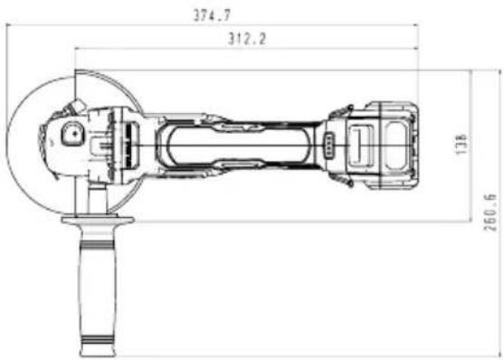
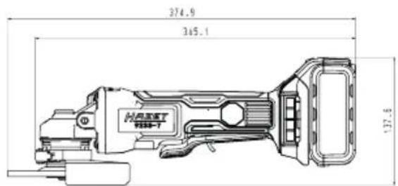
1. Technical data / tool components: Cordless right-angle grinder HAZET 9233-7
| Spindle thread | M14 |
| Battery power | 18V - 5Ah |
| Idle speed | 8,000 rpm |
| Weight without battery pack / | 1.53 kg |
| Sound pressure level LpA / | 89 dB(A) |
| Sound power level LpW / | 100 dB(A) |
| Vibration acceleration | 7.9 m/s ^2 |
| Cut-off wheel | 125 mm x 1.0 |
| Grinding wheel | 125 mm x 6.0 |
| Battery charger HAZET 9212-03 | |
| Input voltage 100 - 240 V~ 50/60 Hz 110 W | |
| Output voltage 12 - 18 V - 4.0 A | |
| Safety approval CB, ETL, GS, ICES, PSE | |
| Battery type Li-Ion | |
| Charging time 80 min | |
| Accessories (optional) Included in delivery | ||
| HAZET No. Designation The HAZET cordless right-angle grinder is delivered in a plastic case | ||
| 9212-02 Replacement battery 2 Ah | The package includes: | |
| 9212-05 Replacement battery 5 Ah | HAZET 9233-7 | |
| HAZET 9212-02 18V / 5.0 Ah Li-Ion battery | ||
| HAZET 9212-03 quick charger | ||

Electrical energy may cause serious injuries! Always wear personal protective equipment!
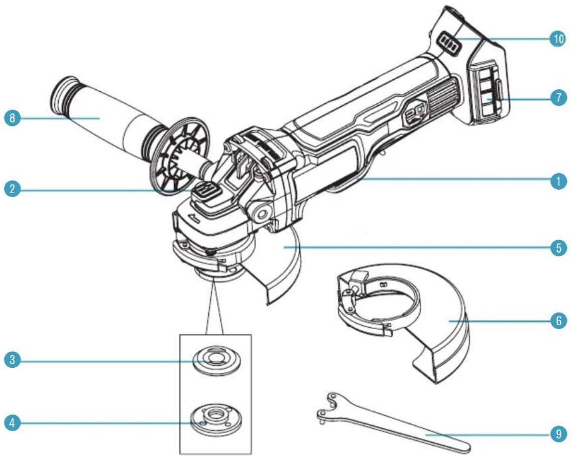
| Pos. | Bezeichnung Pos. | Bezeichnung | ||
| 1 | Paddle switch 6 | Cutting wheel guard | ||
| 2 | Spindle lock 7 | Removable mesh filter cover | ||
| 3 | Backing flange 8 | Auxiliary handle | ||
| 4 | Threaded clamp nut 9 | Wrench | ||
| 5 | Grinding wheel guard 10 | Charge level indicator |

Electrical energy may cause serious injuries!
Always wear personal protective equipment!
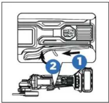
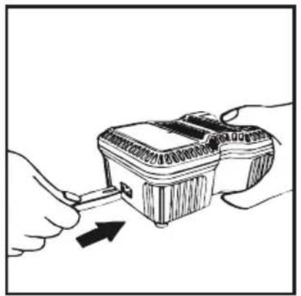
Attaching the rechargeable battery:
- Insert the battery until it locks with a click.
- If it is not engaged, the battery can fall off the tool, become destroyed and/or cause injury to you or bystanders.
- The rechargeable battery is equipped with a charge indicator. The 4-stage LEDs (green) display the remaining capacity.
- Pressing the control button displays the battery's state of charge for 5 seconds.
- The battery has built-in overheating protection and protects the HAZET cordless right-angle grinder and the battery from overheating. When the max. temperature of 70 °C is reached, the battery automatically shuts down and the HAZET cordless right-angle grinder can no longer be operated.
| Charge capacity indicator Status | |||
| 1 LED | 1 0 - 25 % | ||
| 2 LED | 1, 2 | 26 - 50 % | |
| 3 LED | 1, 2, 3 | 51 - 75 % | |
| 4 LED | 1, 2, 3, 4 | 76 - 100 % | |
Disconnecting the battery:
- Press the safety lock and pull the battery from the tool handle.
Before starting operation:
- Clean up the work area.
- Keep unauthorised persons out of the work area.
- Ensure adequate lighting and ventilation in the workplace.
- Make sure that the battery is properly installed and locked into place.
Adjusting the direction of rotation:
- The direction of rotation is set by the reversing switch.
- Forward and reverse are indicated by arrows, which are milled on to the body.
• In forward, the tools rotates clockwise. - In reverse, the direction of rotation is set to counterclockwise.
Overload protection
This angle grinder is fitted with overload protection. If the grinder is excessively forced, or the task being performed is too great, it will automatically go into overload mode. When it goes into overload mode, the tool will automatically and suddenly stop. To reset the overload, simply release the switch. When the paddle switch is pressed again, the tool will restart.
Temperature cut-out
When used as intended, the angle grinder cannot be subjected to overload. But running continuously at full load for a long time will cause the battery pack to overheat. If the allowable battery temperature range is exceeded, the battery pack will automatically stop operating and will not restart until it has cooled to a safe level.
Low-voltage cut-out
The battery pack used on this tool is fitted with a low voltage cut-out feature within the circuitry. The low-voltage cut-out feature operates when the voltage drops below a pre-set value. This feature automatically stops the tool from operating. When this condition occurs, you will need to either insert another battery pack into the tool or recharge the existing battery pack.
Stuck protection
During operation, the tool may suddenly become stuck. If the motor does not stop on time, this would result in stuck and could cause serious injury. This tool detects the change instantly and automatically shuts off the tool safely.
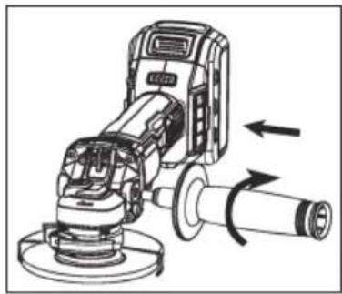
Installing the auxiliary handle
- Remove the battery pack before installing or removing the auxiliary handle.
- Screw the auxiliary handle into the gear housing.
- Tighten the auxiliary handle securely.
natural_image
Technical line drawing of a mechanical grinding machine with directional arrows indicating motion (no text or symbols)
Electrical energy may cause serious injuries! Always wear personal protective equipment!
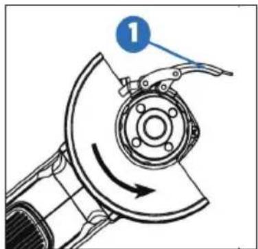
Mounting the wheel guard
It is important to choose the correct guards to use with grinder accessories. See Fig. E for information on choosing the correct accessories.
The grinding wheel guard and the cutting wheel guard are both attached and removed using the same steps:
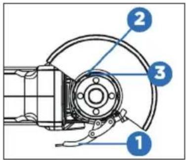
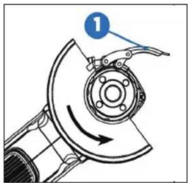
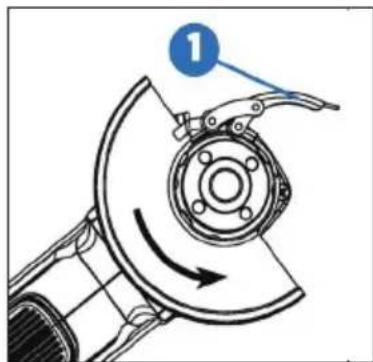
- Open the guard latch (1), and align the lugs (2) on the guard with the slots (3) on the gear case cover.
- Push the guard down until the guard lugs engage and rotate freely in the groove on the gear case hub.
- With the guard latch open, rotate the guard into the desired working position. The guard body should be positioned between the spindle and the operator to provide maximum operator protection.
- Close the guard latch (1) to secure the guard on the gear case. You should not be able to rotate the guard by hand when the latch is closed. Don't operate the grinder with a loose guard or with the guard latch in an open position.
- To remove the guard, open the guard latch, rotate the guard so that the lugs and slots are aligned, and pull up on the guard.
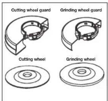
(Fig. E)

Caution!
You can install the auxiliary handle on the left or right side of the grinder, depending on operator preference. It must always be used to prevent loss of control and possible serious injury.
Make sure the handle is tightened before operation. There could be large pressure applied to the handle during operation. Loosening the handle might result in serious injury.

Electrical energy may cause serious injuries! Always wear personal protective equipment!
Adjusting the wheel guard
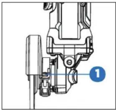
The guard is pre-adjusted to the diameter of the gear case hub at the factory. If, after a period of time, the guard becomes loose, tighten the adjusting screw (1) with the latch in the closed position and the guard installed on the tool.
Spindle lock
The spindle lock button (1) is provided to prevent the spindle from rotating when installing or removing wheels. Operate the spindle lock only when the tool is turned off and the wheel has come to a complete stop.
To engage the lock, press the spindle lock button (1) and rotate the spindle until you are unable to rotate the spindle further.
natural_image
Mechanical assembly diagram showing a component with a blue label pointing to a numbered point (1), no readable text or symbols present.
natural_image
Mechanical assembly diagram showing a robotic arm with a numbered component (1), no text or symbols present.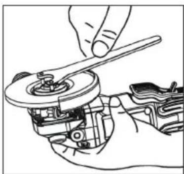
natural_image
Line drawing of a hand using a wrench to adjust a mechanical component (no text or symbols present)
Caution!
Guards must be used with grinding wheels and cut-off wheels. The grinder is provided with a grinding guard intended for use with grinding wheels and a cutting guard intended for use with cutting wheels.
Make sure the wheel guard is locked properly and in protection angle position, otherwise a broken blade might cause serious injury.
To prevent accidental operation, turn off the tool and remove the battery pack before performing the following operations. Failure to do this could result in serious personal injury.
If the guard cannot be tightened by the guard latch, do not use the tool and take the tool and guard to a service centre to repair or replace the guard.

Electrical energy may cause serious injuries!
Always wear personal protective equipment!
Installing and removing the wheel
Depressed centre wheel must be used with the included flanges.
- Turn off the tool and remove the battery pack.
• Install the unthreaded backing flange on the spindle with the raised section (pilot) against the wheel. - Place the wheel against the backing flange, centring the wheel on the raised section (pilot) of the backing flange.
- While pressing the spindle lock button, thread the threaded clamp nut on the spindle.
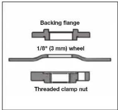
If the wheel you are installing is more than 1/8" (3 mm) thick, place the threaded clamp nut on the spindle so that the raised section (pilot) fits into the centre of the wheel.
If the wheel you are installing is 1/8" (3 mm) thick or less, place the threaded clamp nut on the spindle so that the raised section (pilot) is not against the wheel.
- While pressing the spindle lock button, tighten the threaded clamp nut with the included wrench.
- To remove the wheel, press the spindle lock button and loosen the threaded clamp nut with the included wrench.
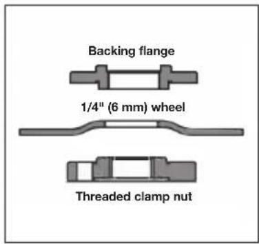
Note:
If the wheel spins after the threaded clamp nut is tightened, check the orientation of the threaded clamp nut. If a thin wheel is installed with the pilot on the clamp nut against the wheel, it will spin because the height of the pilot prevents the clamp nut from holding the wheel.

Caution!
Do not tighten the adjusting screw with the latch in the open position. Undetectable damage to the guard or the mounting hub may result.

Warning!
Do not engage the spindle lock while the tool is operating. Damage to the tool will result and the attached accessory may spin off, possibly resulting in injury.

Warning!
Always take off and remove the battery before changing the accessories. Failure to do this could result in serious personal injury.
Only use accessories with a safe operating speed higher than rated speed of the tool.

Electrical energy may cause serious injuries! Always wear personal protective equipment!
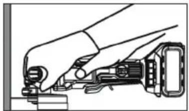
Paddle switch
Grasp the tool body and the auxiliary handle firmly. Push the lock-up button forward (1) and press the paddle (2) to start the tool.
To stop it, release the paddle.
Soft start
With this feature, the tool starts gradually and increases the comfort level.
Electric brake
The electric brake engages when the switch is released, causing the wheel to stop. Generally, the wheel stops within two seconds. However, there may be a delay between the time you release the switch and when the brake engages. Occasionally the brake may miss completely. If the brake misses frequently, the grinder needs servicing by an authorized service facility.
Note:
This tool has no provision to lock the switch in the ON position. The tool should never be locked ON by any means.
Note:
This tool is equipped with an electric brake. When the brake is functioning properly, sparks may be visible through the vent slots in the housing. This is normal and is the action of the brake.

Caution!
After the paddle is released, the wheel will still rotate for 3 seconds. Make sure the wheel stops before laying down the tool.

Electrical energy may cause serious injuries!
Always wear personal protective equipment!
Grinding with grinding wheels
Always carefully select and use grinding wheels that are recommended for the material to be ground. Make sure that the operating speed of any accessory wheel selected is rated at 7500 RPM or more. Pay attention to the dimensions of the grinding tools. The mounting hole diameter must fit the mounting flange without play. Do not use reducers or adaptors.
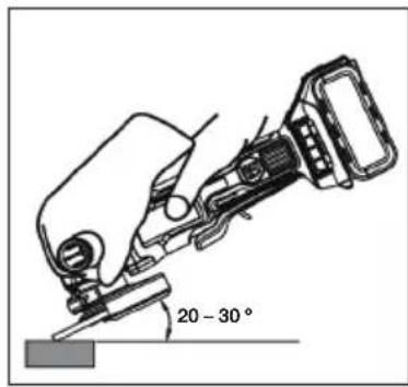
- Secure all work in a vise or clamp to a workbench.
- Hold the grinder in front and away from you with both hands, keeping the grinding wheel clear of the workpiece.
- Turn on the grinder and let the motor and grinding wheel build up to full speed.
- Lower the grinder gradually until the grinding wheel contacts the workpiece.
- Maintain a 20 to 30^ angle between the tool and the work surface.
- Move the grinder continuously at a steady, consistent pace.
- Use just enough pressure to keep the grinder from chattering or bouncing.
- Lift the grinder away from the workpiece before turning off the grinder.
Note:
If the grinder is held in one spot too long, it will gouge and cut grooves in the workpiece. If the grinder is held at too sharp an angle, it will also gouge the workpiece because of concentration of pressure on a small area.
Heavy pressure will decrease the grinder's speed and put strain on the motor. Normally the weight of the tool alone is adequate for most grinding jobs. Use light pressure when grinding jagged edges or loose bolts where there is the potential for the grinder to snag on the metal edge.

Danger!
Never use the grinder with the wheel guard removed and always be sure the wheel guard is locked into place. It has been designed for use only with the wheel guard installed. Attempting to use the grinder with the wheel guard removed will result in loose particles being thrown against the operator resulting in serious personal injury.

Electrical energy may cause serious injuries! Always wear personal protective equipment!
Cutting with cutting wheels
Always carefully select and use cutting wheels that are recommended for the material to be ground. Make sure that the operating speed of any accessory wheel selected is rated at 7500 RPM or more. Pay attention to the dimensions of the grinding tools. The mounting hole diameter must fit the mounting flange without play. Do not use reducers or adaptors.
natural_image
Illustration of a hand using a tool to adjust or install a mechanical component (no text or symbols visible)- Secure all work in a vise or clamp to a workbench.
- Hold the grinder in front and away from you with both hands, keeping the cutting wheel clear of the workpiece.
- Turn on the grinder and let the motor and cutting wheel build up to full speed.
- Allow the tool to reach full speed before touching the tool to the work surface.
- Apply minimum pressure to the work surface, allowing the tool to operate at high speed. The cutting rate is greatest when the tool operates at high speed.
- Once a cut is begun and a notch is established in the workpiece, do not change the angle of the cut. Changing the angle will cause the wheel to bend and may cause wheel breakage.
- Remove the tool from the work surface before turning the tool off. Allow the tool to stop rotating before setting it down.

Warning!
To prevent loss of control and possible serious personal injury, always operate the tool with both hands, keeping one hand on the auxiliary handle.
Do not start the tool on the work piece. Let the wheel reach full speed to work. If started on the work piece, the wheel could kick back and might result in injury.
Make sure the tool stops rotating before laying it down. Otherwise it might cause serious injury.
Avoid placing excessive pressure on the tool. Heavy pressure increases the possibility of the wheel breaking and the motor overheating.

Warning!
The cutting wheel guard must be used while using cutting wheels.
Never change the cutting angle during operation. The change might result in a break or crack in the cut-off wheel.

Electrical energy may cause serious injuries!
Always wear personal protective equipment!
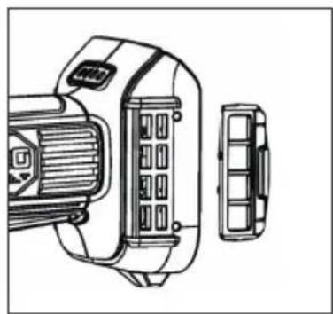
Removable mesh filter cover
The removable mesh filter cover is designed to prevent debris contamination overtime. Take the mesh filter cover out to clean the dust.
natural_image
Technical line drawing of a mechanical device with internal components and a separate view (no text or symbols)
Note:
High operating noise level! Always wear hearing protection!
Before charging:
- Check the power source voltage against the permissible voltage on the charger's name badge.
- Loading voltages higher than allowed represents a fire hazard to the charger.
- Check the cables for damage. Replace any damaged cables prior to use.
- Connect the charger to the power source. All 3 charging LEDs light up for 1 - 2 seconds.
- Slide the battery headfirst with the terminal side into the charger. Make sure that the battery fits in the charger slide and that the contacts snap into position.
- If the charger detects an overheated battery, all 3 charging LEDs flash at the same time. Remove the battery and let the charger cool for about 80 minutes before you continue charging.

natural_image
Illustration of hands using a tool to adjust or install a device (no text or symbols visible)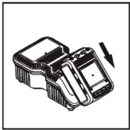
natural_image
Technical line drawing of a mechanical device with an arrow indicating rotation or assembly (no text or symbols present)
If the rechargeable battery is improperly inserted into the charger, then the terminals of the charger can become bent or damaged.
- The state of charge is displayed while charging:
- Less than 30 % charged: all 3 charging LEDs are flashing.
- Less than 60 % charged: one charging LED lights up, the other two are flashing.
- Over 60 % charged: 2 LEDs light up and one is flashing.
- 100 % charged: all 3 charging LEDs light up.
- Charging may take about 65 minutes. Charging is completed when all 3 charging LEDs light up.

Always disconnect the charger from the power source in the event of malfunctions! Reinsert the battery if necessary.
Troubleshooting / Avoidance:
- Never pull the plug from the socket using the cable.
• Always pull the plug to avoid damaging the cable.
- Firmly hold the charger with your hand and remove the battery from the charger.
- The rechargeable battery and the charger heat up slightly during charging. This does not impair its functionality. Appropriate caution is required for operation.
• After charging, take the required 15 minutes of wait time before charging again.
- If the charger detects an overheated battery, all 3 charging LEDs flash at the same time. Remove the battery and let the charger cool for about 15 - 30 minutes before you continue charging.
- If the charger detects a malfunctioning battery, 2 charging LEDs flash at the same time. Please remove the battery and allow it cool for about 15 - 30 minutes. Should both charging LEDs continue to flash afterwards, the battery may be defective. Please send us the battery immediately for analysis.

Electrical energy may cause serious injuries! Always wear personal protective equipment!
③ Design and function
- If the charger has a defect, all 3 charging LEDs flash at the same time. Please remove the battery and disconnect the charger from the mains. After 2 minutes, insert the plug into the socket outlet again and insert the battery. Should all 3 charging LEDs still be flashing, send the charger immediately to us for analysis.
④ Maintenance and Care
Maintenance and care:
- Disconnect the battery from the tool before any maintenance or repair work.
- Check sockets regularly. Worn or damaged sockets can slip off the tool or reduce its performance and thus damage the motor.
Motor maintenance:
- The motor unit winding/coil is the most important part of the electric tool. Handle the tool with care to ensure that the winding/coil is not damaged or gets wet with water or oil.
Care:
• The HAZET cordless impact wrench should be regularly treated with a commercial solvent-free cleaning agent without grinding additives.
Checking for dust:
- Dust can be removed with a soft cloth or a cloth moistened with soapy water.
- Do not use bleach, chlorine-based cleaning agents, benzene or thinner since these can damage the plastic.
- Wash and dry plastic parts with a soft cloth dampened with soapy water.
Spare parts:
- Only use the manufacturer's original spare parts.
- Unsuitable or defective spare parts may cause damage, malfunction or total failure of the device.
- The use of non-approved spare parts will void all warranty, service and liability claims as well as all claims for compensation against the manufacturer or its agents, distributors and sales representatives.

Electrical energy may cause serious injuries! Always wear personal protective equipment!
Storage:

The device must be stored under the following conditions:
- Keep the device in a dry and dust-free place.
- Do not expose the device to liquids and/or aggressive substances.
- Do not store the device outdoors.
- Keep the device out of reach of children.
• Storage temperature: -10 °C to +40 °C.
• Relative air humidity: max. 60 %.
Disposal:

- Worn-out rechargeable batteries (Li-Ion) and electric devices must not be disposed of in domestic waste, but at suitable collecting points.
- Electronic waste, electronic components, lubricants and other auxiliary materials must be treated as hazardous waste and may only be disposed of by authorised specialists!
- Reducing environmental pollution and preserving the environment are at the heart of our activities!

Electrical energy may cause serious injuries! Always wear personal protective equipment!

1. Obecné informace
natural_image
Circular icon depicting a person standing with hands on hips, no text or symbols present.natural_image
Technical line drawing of a mechanical component with directional arrows indicating movement (no text or symbols)natural_image
Technical line drawing of a mechanical device with directional arrows indicating motion or force (no text or symbols)

Opatrně!
natural_image
Mechanical assembly diagram showing a valve mechanism with a numbered label (1) pointing to a component, no readable text or symbols present.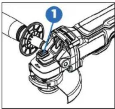
natural_image
Mechanical assembly diagram showing a robotic arm with a numbered component (1), no text or symbols present.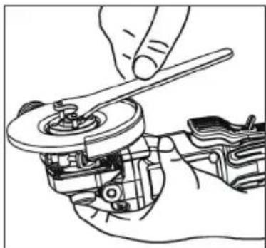
natural_image
Line drawing of a hand using a wrench to adjust a mechanical component (no text or symbols present)
Opatrně!
Upozornění:
natural_image
Illustration of a hand using a mechanical tool to adjust or install a component (no text or symbols visible)natural_image
Technical line drawing of a mechanical device with internal components and a separate view (no text or symbols)
Poznámka:
natural_image
Illustration of hands using a handheld device to interact with a device (no text or symbols visible)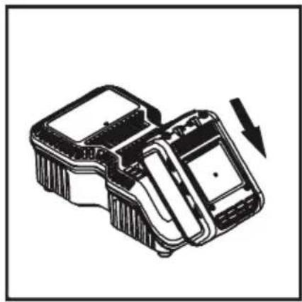
natural_image
Technical line drawing of a mechanical device with an arrow indicating rotation or assembly (no text or symbols present)
| Pozicija | Oznaka | Pozicija | Oznaka |
| 1 Prekidač 6 Zaštita od iskre (rezne ploče) | |||
| 2 Zaključavanje osovine 7 Poklopac sa mrežicom | filtra koji se može mijenjati | ||
| 3 Stražnja prirubnica 8 Drška sa zaštitom | |||
| 4 Stezna matica 9 Ključ | |||
| 5 Zaštita od iskrenja (brušenje) 10 Indikator punjenja | |||

natural_image
Technical line drawing of a mechanical component with directional arrows indicating movement (no text or symbols)Prije pokretanja:
natural_image
Technical line drawing of a mechanical device with rotating components and directional arrows indicating motion (no text or symbols)
Električni udar struje može uzrokovati ozbiljne ozljede Uvijek koristite osobna sredstva za zaštitu!
Pričvrstite zaštitu od iskrenja
Važno je osigurati da se za pribor za rezanje i brušenje uvijek koristi odgovarajuća zaštita od iskrenja. Pogledajte za informacije o odabiru odgovarajuće opreme.


Pažnja!
natural_image
Mechanical assembly diagram showing a valve mechanism with a numbered label (1) pointing to a component, no readable text or symbols present.natural_image
Mechanical assembly diagram showing a robotic arm with a numbered component (1), no text or symbols present.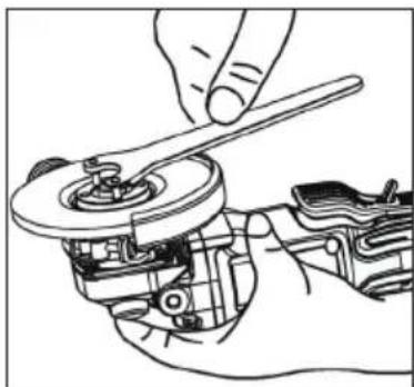
natural_image
Line drawing of a hand using a wrench to adjust a mechanical component (no text or symbols present)
Pažnja!
Kad koristite ploče za rezanje ili brušenje, uvijek se mora koristiti zaštita od iskrenja. Alat za brušenje opremljen je zaštitom od iskrenja za rezanje i brušenje kotača. Uvijek se mora koristiti ispravna zaštita od iskrenja.
Mora se osigurati da je zaštita od iskrenja pravilno zaključana pod pravim kutom. U suprotnom, slomljena ploča može uzrokovati ozbiljne ozljede.
Da biste izbjegli slučajni rad, alat morate isključiti i izvaditi bateriju prije nego što izvršite sljedeće korake. U suprotnom može doći do ozbiljnih ozljeda.
Ukoliko se zaštita od iskrenja ne može montirati pomoću bravice tada, se alat ne smije koristiti. već se alat i zaštita od iskrenja moraju zamijeniti ili odnijeti u servisni centar

Električni udar struje može uzrokovati ozbiljne ozljede Uvijek koristite osobna sredstva za zaštitu!
Električna kočnica
Električna kočnica se aktivira čim otpustite prekidač. To će zaustaviti ploču za rezanje ili brušenje. Obično to traje dvije sekunde. Međutim, aktiviranje kočnice može se odgoditi nakon otpuštanja prekidača. Povremeno se kočnica možda uopće neće aktivirati. Ako se to često događa, brusilica se mora servisirati u ovlaštenom servisu.
Savjet:
natural_image
Line drawing of a hand using a tool to adjust or install a mechanical component (no text or symbols visible)- Sve radne dijelove stegnite u škripac ili ih pričvrstite na radnu površinu.
- Brusilicu držite čvrsto sa obje i dalje od tijela. Rezni disk ne smije u radu strugati ili dodirivati štitnik iskrenja.
- Uključite brusilicu i pričekajte da motor i ploča za rezanje postignu punu brzinu.
- Prije spuštanja alata, na radnu površinu materijala koji se obrađuje, sačekajte trenutak sve dok alat ne postigne punu brzinu
- Pritisnite samo blagi pritisak na površinu materijala koji se obrađuju kako bi stroj mogao raditi pri velikim brzinama. Učinkovitost rezanja je najveća kada se alat koristi velikom brzinom.
- Kad je rez počeo, a na obradi se stvorio zarez, kut reza više se ne smije mijenjati. Promjena kuta rezanja dovodi do savijanja reznog diska, što može rezultirati pucanjem reznog diska.
- Prije isključivanja brusilice, odmaknite je od radnog materijala i može se odložiti samo kada je disk potpuno zaustavljen.

Upozorenje!
Da biste izbjegli gubitak kontrole nad alatom i mogućih ozbiljnih ozljeda, alatom se mora uvijek rukovati objema rukama. Jednu ruku uvijek držite na ručki alata.
Alat se ne smije pokrenuti dok je prislonjen na površinu koja se obrađuje. Da bi ispravno radio, alat prvo mora dostići punu brzinu. Ako se alat drži na na radnom komadu koji se obrađuje, može doći do povratnog udarca i ozljeda.
Mora se paziti da se alat odloži samo kad je ploča potpuno zaustavljena. U suprotnom može doći do ozbiljnih ozljeda.
Nemojte vršiti prekomjerni pritisak na rezni disk jer preveliki pritisak povećava mogućnost da se rezni disk pokvari ili da se motor pregrijava.

Upozorenje!
Pri uporabi reznih diskova mora se instalirati zaštita od iskrenja za rezanje diskova. Kut reza nikada se ne smije mijenjati tijekom rada. Ispravljanje kuta moglo bi slomiti ili rastrgati rezni disk.

Električni udar struje može uzrokovati ozbiljne ozljede Uvijek koristite osobna sredstva za zaštitu!
natural_image
Technical line drawing of a mechanical device with internal components and a separate view (no text or symbols)
Bilješka:
Glasan radni šum! Apsolutno Nosite štitnike za uši!
Prije početka postupka punjenja
- Usporedite napon izvora napajanja s dopuštenim naponom na naljepnici na punjaču.
- Pri punjenju s naponima većim od dopuštenih, postoji rizik od oštećenja punjača.
- Provjerite ima li kabela oštećenja. Oštećene kabele prije uporabe morate zamijeniti.
- Priključite punjač na izvor napajanja. Sve 3 LED lampice za punjenje svijetle 1 - 2 sekunde.
- Gurnite bateriju naopako s priključnom stranom u punjač. Provjerite je li baterija naslonjena na stanicu punjača i da li kontakti stoje na svom mjestu.
- Ako punjač otkrije pregrijavanje baterije, sve će 3 LED-ice za punjenje istovremeno bljeskati. Izvadite bateriju i ostavite da se punjač ohladi oko 80 minuta prije nastavka postupka punjenja.

Električni udar struje može uzrokovati ozbiljne ozljede Uvijek koristite osobna sredstva za zaštitu!
natural_image
Illustration of a hand inserting a plug into a device with an arrow indicating the insertion (no text or symbols present)
natural_image
Technical line drawing of a mechanical device with a downward arrow indicating motion (no text or symbols)
natural_image
Worker in a factory grinding metal with sparks flying, wearing safety gear and a S47-branded work shirt (no visible text or symbols)HAZET-WERK Hermann Zerver GmbH & Co. KG • 📄 Güldenwerther Bahnhofstrasse 25-29 42857 REMSCHEID • ✉ 10 04 61 • 42804 REMSCHEID • GERMANY • 📞 +49 (0) 21 91 / 7 92-0 FAX +49 (0) 21 91 / 7 92-375 (Deutschland) -400 (International) • www.hazet.de • e-mail info@hazet.de