
BRC1H519K - Remote control DAIKIN - Free user manual and instructions
Find the device manual for free BRC1H519K DAIKIN in PDF.

| Brand | Daikin |
| Model | BRC1H519K |
| Product Type | Remote Control for Air Conditioner |
| Dimensions (Approx.) | 150 x 50 x 20 mm |
| Weight (Approx.) | 100 g (including batteries) |
| Power Source | 2 x AAA alkaline batteries (not included) |
| Operating Temperature Range | 0°C to 50°C |
| Compatibility | Daikin split-type air conditioners (select models) |
| Key Functions | On/Off, Mode (Cool, Heat, Fan, Dry), Temperature adjustment, Fan speed, Swing, Timer, Sleep mode |
| LCD Display | Backlit LCD showing set temperature, mode, fan speed, timer, battery level |
| Wireless Range | Up to 8 meters in open space |
| Cleaning Instructions | Wipe with a soft, dry cloth. Do not use water or cleaning agents. |
| Battery Replacement | When display dims or no response, replace both batteries with new ones. |
| User-Serviceable Parts | Batteries only. No other internal components are user-serviceable. |
| Safety Precautions | Keep away from water and moisture. Do not drop. Dispose of batteries properly. |
| Warranty | 1-year limited warranty (check local terms) |
| Country of Origin | Japan / Thailand (varies by production batch) |
Frequently Asked Questions - BRC1H519K DAIKIN
User questions about BRC1H519K DAIKIN
0 question about this device. Answer the ones you know or ask your own.
Ask a new question about this device
Download the instructions for your Remote control in PDF format for free! Find your manual BRC1H519K - DAIKIN and take your electronic device back in hand. On this page are published all the documents necessary for the use of your device. BRC1H519K by DAIKIN.
USER MANUAL BRC1H519K DAIKIN
Installer and user reference guide
Wired remote controller
natural_image
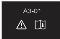
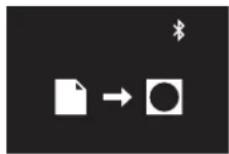
Circular icon with a black square and three white plus signs below (no text or symbols)Table of contents
1 General safety precautions 3
1.1 For the user .... 3
1.2 For the installer.... 3
2 About this document 4
For the user 4
3 Buttons 4
4 Home screens 4
5 Status icons 5
6 Operation 5
6.1 Operation mode....5
6.1.1 About the operation modes.... 6
6.1.2 To set the operation mode.... 6
6.2 Setpoint 6
6.2.1 About the setpoint.... 6
6.2.2 To set the setpoint 7
6.3 Date and time 7
6.3.1 About date and time.... 7
6.3.2 To set date and time 7
6.4 Airflow....7
6.4.1 Airflow direction....7
6.4.2 Fan speed 8
6.5 Ventilation....8
6.5.1 Ventilation mode 8
6.5.2 Ventilation rate 9
6.6 Advanced operation 9
6.6.1 To make a Bluetooth connection 9
7 Maintenance and service 9
7.1 Overview: Maintenance and service 9
8 Troubleshooting 9
8.1 Overview: Troubleshooting....9
8.2 Refrigerant leak detection 9
8.2.1 To stop the leak detection alarm....9
For the installer
9
9 About the box
9.1 To unpack the controller.... 9
10 Preparation
10.1 Wiring requirements 10
10.1.1 To prepare the wiring for installation.... 10
11 Installation
11.1 Overview: Installation 10
11.2 Mounting the controller.... 10
11.2.1 About mounting the controller.... 10
11.2.2 To mount the controller.... 10
11.3 Connecting the electrical wiring.... 10
11.3.1 Precautions when connecting electrical wiring ..... 10
11.3.2 To connect the electrical wiring.... 11
11.4 Closing the controller.... 11
11.4.1 Precautions when closing the controller 11
11.4.2 To close the controller.... 11
11.5 Opening the controller 11
11.5.1 Precautions when opening the controller.... 11
11.5.2 To open the controller.... 11
12 Starting up the system
12.1 Master and slave controller 12
12.2 To designate a controller as slave.... 12
13 Operation
13.1 Buttons 13
13.2 Screen.... 13
13.3 Status indicator.... 13
13.4 Information 13
13.4.1 Information screen 13
13.4.2 Information menu.... 14
14 Configuration
14.1 Installer menu.... 14
14.1.1 About the installer menu 14
14.1.2 Screen settings 14
14.1.3 Status indicator settings.... 15
14.1.4 Field settings.... 15
14.1.5 Miscellaneous settings.... 20
14.2 Remote controller software update 28
14.2.1 To update the software with Updater 28
15 About the app
15.1 Operation and configuration overview 28
15.2 Pairing 28
15.2.1 About pairing.... 28
15.2.2 To pair the app with a controller.... 28
15.3 Installer mode.... 28
15.3.1 About installer mode 28
15.3.2 To activate Installer mode.... 28
15.3.3 To deactivate Installer mode.... 28
15.3.4 To make Installer mode settings.... 28
15.4 Demo mode 29
15.4.1 About demo mode.... 29
15.4.2 To launch demo mode 29
15.4.3 To exit demo mode 29
15.5 Functions.... 29
15.5.1 Overview: Functions 29
15.5.2 Remote controller firmware update.... 29
15.5.3 Notifications 30
15.5.4 Master/slave status 30
15.5.5 Screen.... 30
15.5.6 Status indicator 30
15.5.7 Date and time.... 30
15.5.8 About 30
15.5.9 Remove bonding information 30
15.5.10 Setpoint mode 30
15.5.11 Setback 30
15.5.12 Individual airflow direction.... 31
15.5.13 Setpoint range.... 31
15.5.14 Airflow direction range 31
15.5.15 Draught prevention 31
15.5.16 Presence detection 31
15.5.17 Errors and warnings.... 32
15.5.18 Unit number 32
15.5.19 Filter auto clean 32
15.5.20 AirNet address 32
15.5.21 Group address 32
15.5.22 Field settings.... 32
15.5.23 Duty rotation.... 33
15.5.24 Test operation 33
16 Maintenance
16.1 Maintenance safety precautions.... 34
16.2 About maintenance 34
16.3 To remove a warning screen.... 34
16.4 To clean the controller 35
17 Troubleshooting
17.1 Error codes of the indoor unit 35
18 Technical data 36
18.1 Connection diagram 36
18.1.1 Typical layout 36
18.1.2 Typical layout for group control.... 36
18.1.3 Controller + DIII central control equipment 37
1 General safety precautions
Please read these general safety precautions carefully before installing air conditioning equipment, and be sure to install the equipment correctly.
Failure to follow these instructions properly may result in property damage or personal injury, which may be serious depending on the circumstances.
Meaning of warnings and symbols
These safety messages are used to attract your attention. The meaning of each safety message is described below:

WARNING
Indicates a situation that could result in death or serious injury.

CAUTION
Indicates a situation that could result in minor or moderate injury.

DANGER
Indicates a situation that results in death or serious injury.

DANGER: RISK OF EXPLOSION
Indicates a situation that could result in explosion.

INFORMATION
Indicates useful tips or additional information.

NOTICE
Indicates a situation that could result in equipment or property damage.
1.1 For the user

INFORMATION
Also see the operation manual delivered with the outdoor and indoor unit.

WARNING
Do NOT play with the unit or its remote controller. Accidental operation by a child may result in impairment of bodily functions and harm health.

WARNING
To prevent electric shocks or fire:
- Do NOT operate the controller with wet hands.
- Do NOT disassemble the controller and touch interior parts. Contact your dealer.
- Do NOT modify or repair the controller. Contact your dealer.
- Do NOT relocate or reinstall the controller by yourself. Contact your dealer.

WARNING
Do NOT use flammable materials (e.g. hairspray or insecticide) near the controller.

NOTICE
To clean the controller, do NOT use organic solvents, such as paint thinner. Possible consequence: damage, electric shock, or fire.
1.2 For the installer
The precautions described in this document cover very important topics, follow them carefully.

INFORMATION
This controller is an option and cannot be used standalone. Also see the installation and operation manual of the indoor and outdoor units.

NOTICE
Improper installation or attachment of equipment or accessories could result in electric shock, short-circuit, leaks, fire or other damage to the equipment. Only use accessories, optional equipment and spare parts made or approved by Daikin.

WARNING
All field wiring and components MUST be installed by a licensed electrician and MUST comply with the applicable legislation.

NOTICE
The remote controller MUST be mounted indoors.

NOTICE
When the controller is used as room thermostat, select an installation location where the average temperature in the room can be detected.
Do NOT install the controller in the following places:
- In places that are exposed to direct sunlight.
- In places that are near a heat source.
- In places that are affected by outside air or air draught due to e.g. door opening/closing.
- In places where the display can easily get dirty.
- In places where there is NO easy access to the controls.
- In places with temperatures < -10^ and >50^ .
- In places where the relative humidity is >95%.
- In places where there is machinery that emits electromagnetic waves. Electromagnetic waves may disturb the control system, and cause malfunction of the equipment.
- In places where it may be exposed to water, or in generally moist areas.
If you are NOT sure how to install or operate the unit, contact your dealer.
After finishing installation:
- Conduct a trial operation to check for faults.
- Explain the user how to operate the controller.
- Ask the user to store the manual for future reference.

INFORMATION
Consult your dealer regarding the relocation and reinstallation of the controller.
2 About this document
Target audience
Authorised installers + end users
Documentation set
This document is part of a documentation set. The complete set consists of:
- Installation and operation manual:
- Installation instructions
- Basic operation instructions
- Format: Paper (in the box of the controller)
- Installer and user reference guide:
- Extended installation and operation information
- Format: Digital files on http://www.daikineurope.com/support-and-manuals/product-information/
- Madoka Assistant in-app documentation:
- The controller only allows for basic settings and operation. Advanced settings and operation are performed via the Madoka Assistant app. For more information, see the app and its in-app documentation.
- Format: App available from Google Play and the Apple Store
- Declaration of conformity:
- Hereby, Daikin Europe N.V. declares that the radio equipment type BRC1H is in compliance with the Directive 2014/53/EU. The original declaration of conformity is available from the BRC1H product page http://www.daikin.eu/BRC1H.
- Format: Digital file from the product page

Latest revisions of the supplied documentation may be available on the regional Daikin website or via your dealer.
The original documentation is written in English. All other languages are translations.
Technical engineering data
- A subset of the latest technical data is available on the regional Daikin website (publicly accessible).
- The full set of latest technical data is available on the Daikin extranet (authentication required).
For the user
3 Buttons
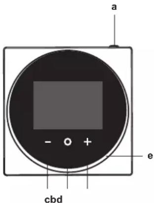
a ON/OFF
- When OFF, press to turn ON the system. As a result, the status indicator (e) will turn ON too.
- When ON, press to turn OFF the system. As a result, the status indicator (e) will turn OFF too.
b ENTER/ACTIVATE /SET
- From the home screen, enter the main menu.
- From the main menu, enter one of the submenus.
- From their respective submenu, activate an operation/ventilation mode.
- In one of the submenus, confirm a setting.
c — CYCLE/ADJUST
- Cycle left.
- Adjust a setting (default: decrease).
d + CYCLE/ADJUST
- Cycle right.
- Adjust a setting (default: increase).

INFORMATION
The behaviour of the status indicator is according to field settings. For more information, see "14.1.3 Status indicator settings" on page 15.
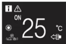
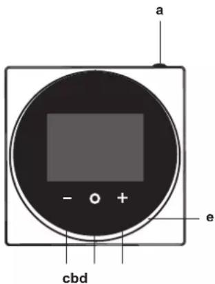
4 Home screens
Depending on installer configuration, the controller either has a standard or a detailed home screen. In most cases, the standard home screen gives you only the active operation mode, messages (if any), and the setpoint temperature (in case of Cooling, Heating, or Auto operation mode). The detailed home screen gives you all kinds of information through status icons.
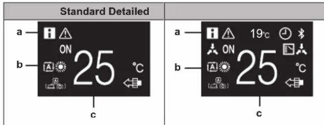
a Messages
b Active operation mode
c Setpoint temperature

INFORMATION
The controller is equipped with a power saving function that causes the screen to go blank after a period of inactivity. To make the screen light up again, press one of the buttons.
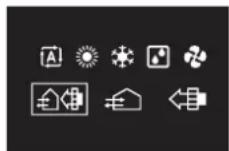
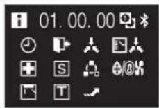
5 Status icons
| Icon Description | |
 | System operation ON. Indicates that the system is in operation. |
 | System operation OFF. Indicates that the system is NOT in operation. |
 | Bluetooth.1 Indicates that the controller is communicating with a mobile device, for use with the Madoka Assistant app. |
 | Centralised control. Indicates that the system is controlled by central control equipment (optional accessory) and that control of the system by the controller is limited. |
 | Changeover under centralised control. Indicates that the cooling/heating changeover is under centralised control by another indoor unit, or by an optional cool/ heat selector that is connected to the outdoor unit. |
 | Defrost/Hot start. Indicates that the defrost/hot start mode is active. |
 | Timer. Indicates that the schedule timer or OFF timer is enabled. |
 | Clock not set. Indicates that controller's clock is not set. |
 | Self-cleaning filter operation. Indicates that self-cleaning filter operation is active. |
 | Quick Start. Indicates that Quick Start mode is active (Sky Air only). |
 | Test operation. Indicates that Test Operation mode is active (Sky Air only). |
 | Inspection. Indicates that the indoor or outdoor unit is being inspected. |
 | Periodic inspection. Indicates that the indoor or outdoor unit is being inspected. |
 | Backup. Indicates that in the system an indoor unit is set as backup indoor unit. |
 | Individual airflow direction. Indicates that the individual airflow direction setting is enabled. |
 | Information. Indicates that the system has a message to convey. To see the message, go to the information screen. |
 | Warning. Indicates that an error occurred, or that an indoor unit component needs to be maintained. |
 | Demand control. Indicates that the system's energy consumption is being limited, and that it is running with restricted capacity. |
 | End of demand control. Indicates that the system's energy consumption is no longer being limited, and that it is no longer running with restricted capacity. |
 | Rotation. Indicates that Rotation mode is active. |
 | Setback. Indicates that the indoor unit is operating under setback conditions. |
Icon Description
Ventilation. Indicates that a heat reclaim ventilation unit is connected.

INFORMATION
- For information on the operation mode and ventilation mode icons, see "6.1 Operation mode" on page 5 and "6.5.1 Ventilation mode" on page 8 respectively.
- Most icons are related to things set in the Madoka Assistant app. For more information, see the app.
6 Operation
From the home screen, press 📄 to enter the main menu. Use and + cycle through the menus. Press ag 📄 to enter one of the menus.

INFORMATION
- Depending on the type of indoor unit you are operating, more or less menus may be available.
- In the main menu, the icon for each menu reflects the current active setting or mode. When operating the controller, the menu you navigate through can look different from that represented in this manual.
- The controller only allows for basic operation of the system. For advanced operation (setback, schedule timer, ...), see the Madoka Assistant app.
6.1 Operation mode
The indoor unit can operate in various operation modes.
| Icon Operation mode | |
 | Cooling. In this mode, cooling will be activated as required by the setpoint, or by Setback operation.. |
 | Heating. In this mode, heating will be activated as required by the setpoint, or by Setback operation. |
 | Fan Only. In this mode, air circulates without heating or cooling. |
 | Dry. In this mode, the air humidity will be lowered with a minimal temperature decrease.The temperature and fan speed are controlled automatically and cannot be controlled by the controller.Dry operation will not function if the room temperature is too low. |
 | Ventilation.In this mode, the space gets ventilated, but not cooled or heated. |
 | Air Clean. In this mode, the optional air cleaning unit operates. |
 | Ventilation + Air Clean. Combination of ventilation and air clean operation. |
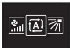
 | Auto. In Auto mode, the indoor unit automatically switches between heating and cooling mode, as required by the setpoint. |
 | |

INFORMATION
Depending on the indoor unit, more or less operation modes are available.
6.1.1 About the operation modes

INFORMATION
If the indoor unit is a cooling-only model, it can only be set to run in Cooling, Fan only, or Dry operation mode.

INFORMATION
If the operation mode changeover of an indoor unit is under centralised control ('changeover under centralised control' status icon blinking in the home screen), then it is NOT possible to change the operation mode of that indoor unit. For more information, see "Switch Cooling/Heating master" on page 26.
Cooling
If the outdoor air temperature is high, it can take some time until the indoor room temperature reaches the setpoint temperature.
When the indoor room temperature is low, and the indoor unit is set to run in Cooling operation mode, the indoor unit can enter Defrost operation mode first (i.e. Heating operation), this to prevent a decrease of the system's cooling capacity due to frost on the heat exchanger. For more information, see "Heating" on page 6.
The indoor unit can run in Cooling operation mode because it is operating under Setback conditions. For more information, see "15.5.11 Setback" on page 30.
Heating
When running in Heating operation mode, the system requires a longer time to reach the setpoint temperature than when running in Cooling operation mode. To make up for this, it is recommended to let the system start operation in advance by making use of the timer function.
The indoor unit can run in Heating operation mode because it is operating under Setback conditions. For more information, see "15.5.11 Setback" on page 30.
To prevent cold drafts and a reduction of the system's heating capacity, the system can run in the following special heating operation modes:
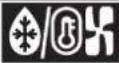
| Operation Description | |
Defrost To prevent the loss of heating capacity due to frost accumulation in the outdoor unit, the system will automatically switch to defrost operation.During defrost operation, the indoor unit fan will stop operation, and the following icon will appear on the home screen: The system will resume normal operation after approximately 6 to 8 minutes. The system will resume normal operation after approximately 6 to 8 minutes. | |
Hot start (VRV only) During hot start, the indoor unit fan will stop operation, and the following icon will appear on the home screen: | |

INFORMATION
When the system is stopped while the indoor unit is running in Heating operation mode, the fan will continue to operate for approximately 1 minute, this to get out any heat remaining in the indoor unit.

INFORMATION
- The lower the outdoor air temperature, the lower the heating capacity. If the system's heating capacity is insufficient, it is recommended to include another heating appliance into the setup (if you use a combustion appliance, ventilate the room regularly. Also, do not use the heating appliance in places where it is exposed to the airflow of the indoor unit).
- The indoor unit is of the hot air circulation type. As a result, after operation start, it takes the indoor unit some time to warm up the room.
- The indoor unit fan will automatically operate until the indoor temperature of the system rises to a certain level.
- When hot air stays under the ceiling and your feet feel cold, it is recommended to include a circulator into the setup.
Dry

NOTICE
To prevent water leakage or system failure, do NOT turn off the system immediately after indoor unit operation. Before turning off the system, wait until the drain pump finishes discharging any water remaining in the indoor unit (approximately 1 minute).

INFORMATION
To ensure a smooth start, do not turn off the system while it is operating.
6.1.2 To set the operation mode
1 Navigate to the operation mode menu.
2 Use - and + to select an operation mode.
3 Press ☐ to activate.
Result: The indoor unit changes its operation mode and the controller returns to the home screen.
6.2 Setpoint
The setpoint is the target temperature for the Cooling, Heating, and Auto operation modes.
6.2.1 About the setpoint
The setpoint that is displayed on the home screen depends on ON/OFF status, and on whether Setback is enabled:
| When ... then ... | |
| ... the system is turned ON ... the | home screen displays the regular temperature setpoint. |
| ... the system is turned OFF, and Setback is disabled | ... the home screen displays the regular temperature setpoint. |
| ... the system is turned OFF, and Setback is enabled | ... the home screen displays the Setback temperature setpoint. |
For information about Setback, see "15.5.11 Setback" on page 30.
6.2.2 To set the setpoint
Prerequisite: The active operation mode is either 'Cooling', 'Heating', or 'Auto'.
1 In the home screen, use

to just the setpoint.
Result: The indoor unit changes its temperature setpoint.
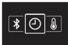
6.3 Date and time
Set the date and time for the indoor units connected to the controller.
6.3.1 About date and time
Depending on daylight saving time settings, the date and time menu has the following daylight saving time indicators:
 | Summer time |
 | Winter time |
For more information, see "Indoor unit field settings" on page 18 (remote controller settings) and "15.5.7 Date and time" on page 30 (app settings).
6.3.2 To set date and time
1 Navigate to the date and time menu.
2 Press


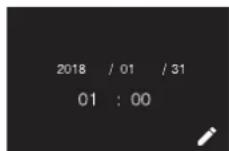
Result: The fields become editable.
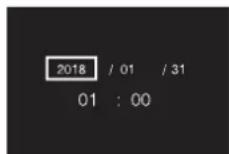
3 Set the date and time. Set with - and . + confirm with . Cycle through the menu until all fields are set correctly.
Result: You set the date and the time.

INFORMATION
Confirming the value in a field will automatically bring you to the next field. To finish making settings and leave the menu, navigate to and confirm the value in the last field.
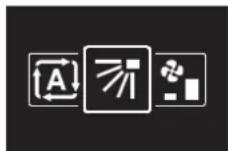
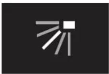
6.4 Airflow
6.4.1 Airflow direction
The airflow direction is the direction in which the indoor unit blows its air.
About airflow direction
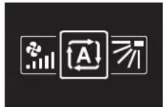
The following airflow directions can be set:
| Direction Screen | ||
| Fixed position. The indoor unit blows air in 1 of 5 fixed positions. | 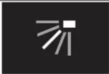 | |
| Swing. The indoor unit alternates between the 5 positions. | 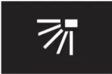 | |
| Auto. The indoor unit adjusts its airflow direction according to movement sensed by a movement sensor. | 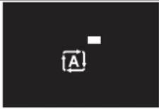 | |

INFORMATION
- Depending on the type of indoor unit, and/or on system layout and organisation, Auto airflow direction may not be available.
- For some types of indoor unit, you cannot set the airflow direction.
Automatic airflow control
In the following operating conditions, the airflow direction of the indoor units is controlled automatically:
- When the room temperature is higher than the controller's setpoint for Heating operation (including Auto operation).
- When the indoor units run in Heating operation mode, and the Defrost function is active.
- When the indoor units run in Continuous operation, and the airflow direction is Horizontal.
To set the airflow direction
1 Navigate to the airflow direction menu.
2 Use

to just the airflow direction.
6 Operation
3 Press to confirm.
Result: The indoor unit changes its airflow direction and the controller returns to the home screen.
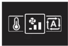
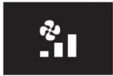
6.4.2 Fan speed
The fan speed is the strength of the airflow coming out of the indoor unit.
About fan speed
Depending on the indoor unit, you can choose between either:
Some indoor units additionally support Automatic fan speed. In this case, the indoor unit adjusts its fan speed automatically, according to the setpoint and indoor temperature.
| Fan speed Screen | |
| Automatic |  |

INFORMATION
- For mechanical protection purposes, it is possible that the indoor unit switches itself to 'Automatic fan speed' mode.
- If the fan stops operating, this does not necessarily mean system failure. The fan can stop operating at all times.
- It may take some time before changes made to fan speed settings are actually carried out.
To set the fan speed
1 Navigate to the fan speed menu.
2 Use

to +

ust the fan speed.
3 Press

onfirm.
Result: The indoor unit changes its fan speed and the controller returns to the home screen.
6.5 Ventilation

INFORMATION
Ventilation settings can ONLY be made for heat reclaim ventilation units.
6.5.1 Ventilation mode
The heat reclaim ventilation unit can operate in various operation modes.
| Icon Ventilation mode | |
 | Energy Reclaim Ventilation. The outdoor air is supplied to the room after passing through a heat exchanger. |
 | Bypass. The outdoor air is supplied to the room without passing through a heat exchanger. |
 | Auto. To ventilate the room in the most efficient way, the heat reclaim ventilation unit automatically switches between "Bypass" and "Energy Reclaim Ventilation" mode (based on internal calculations). |

INFORMATION
Depending on the heat reclaim ventilation unit, more or less ventilation modes are available.

NOTICE
Before starting up the system, the unit MUST be energised for at least 6 hours to avoid compressor breakdown during startup.

INFORMATION
To ensure a smooth start, do not turn off the system while it is operating.
To set the ventilation mode
1 Navigate to the ventilation mode menu.
2 Use

to +

ect a ventilation mode.
3 Pres

ctivate.
Result: The heat reclaim ventilation unit changes its operation mode and the controller returns to the home screen.
6.5.2 Ventilation rate
The ventilation rate is the fan speed during ventilation operation.
To set the ventilation rate
1 Navigate to the ventilation rate menu.
2 Use

to just the ventilation rate.
3 Press

onfirm.
Result: The heat reclaim ventilation unit changes its ventilation rate and the controller returns to the home screen.
6.6 Advanced operation
The controller only allows for basic operation. For advanced operation, use the Madoka Assistant app.
6.6.1 To make a Bluetooth connection
Prerequisite: You have a mobile device on which the Madoka Assistant app is installed and running.
Prerequisite: Your mobile device supports Bluetooth version 4.2.
1 Open the Madoka Assistant app and follow the instructions from there.
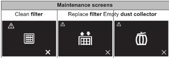
7 Maintenance and service
7.1 Overview: Maintenance and service
When the system needs to be maintained or serviced, consult your dealer.
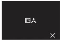
When the following indoor unit components are due for maintenance, you will be confronted by a maintenance screen as soon as you try to enter the main menu:
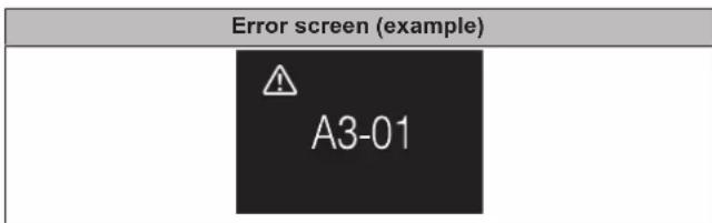
8 Troubleshooting
8.1 Overview: Troubleshooting
When the system is in error and the controller presents you with an error screen as soon as you try to enter the main menu, consult your dealer.
8.2 Refrigerant leak detection
When the system detects a refrigerant leak, an alarm goes off. Stop the alarm and consult your dealer.
8.2.1 To stop the leak detection alarm
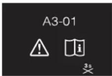
1 Press

seconds to stop the alarm.
Result: The alarm stops.
2 Consult your dealer.
For the installer
9 About the box
9.1 To unpack the controller
1 Open the box.
2 Separate the accessories.
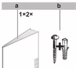
a Installation and operation manual b Wood screws + wall plugs (∅4.0×
10 Preparation
10 Preparation
10.1 Wiring requirements
All wiring must comply with the following requirements:
| Wire specification Value | |
| Type Sheathed vinyl cord or cable | (2 wires) |
| Section 0.75~1.25 mm | ^2 |
| Maximum length 500 m |
10.1.1 To prepare the wiring for installation
1 Peel the sheath of the part of the cable that needs to pass through the inside of the rear casing (L), according to the figure and the table.
2 Keep a 10 mm distance between the length of the 2 wires.
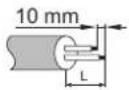
| Wiring outlet L | |
| Top ±150 mm | |
| Left ±120 mm | |
| Bottom ±100 mm | |
| Rear No requirements | |
11 Installation
11.1 Overview: Installation
The installation of the controller typically consists of the following stages:
1 Determining how you want to route the electrical wiring, and nipping away a piece of the rear casing accordingly.
2 Mounting the rear casing to the wall.
3 Connecting the electrical wiring.
4 Closing the controller.
11.2 Mounting the controller
11.2.1 About mounting the controller
Before you can mount the controller, you have to determine the wiring routing, and accordingly, remove a piece of the controller's rear casing.
The wiring can be routed from the top, the rear, the left, or the bottom. Remove a piece of the rear casing according to the illustration:
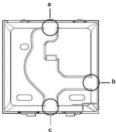
a Wiring from the top
b Wiring from the left
c Wiring from the bottom
In case you are routing the wiring from the rear, you don't have to remove anything.

INFORMATION
When routing the wiring from the top or from the rear, insert the wiring through the knockout hole before mounting the rear casing to the wall.
11.2.2 To mount the controller
1 Take the screws and plugs from the accessory bag.
2 Mount the rear casing to a flat surface.
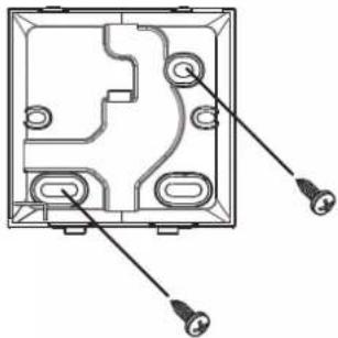
natural_image
Technical diagram of an electrical enclosure with mounting holes and wiring (no text or labels)
NOTICE
Be careful not to distort the rear casing by overtightening the mounting screws.
11.3 Connecting the electrical wiring
11.3.1 Precautions when connecting electrical wiring

INFORMATION
Also read the precautions and requirements in the following chapters:
- General safety precautions
- Preparation

WARNING
All field wiring and components MUST be installed by a licensed electrician and MUST comply with the applicable legislation.

CAUTION
When connecting the controller to the indoor unit, make sure the indoor unit switchbox and transmission wiring are not connected.

NOTICE
The wiring for connection is NOT included.

NOTICE
When wiring, run the wiring away from the power supply wiring in order to avoid receiving electric noise (external noise).

INFORMATION
P1 and P2 have no polarity.
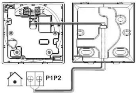
11.3.2 To connect the electrical wiring
Connect controller terminals P1/P2 to indoor unit terminals P1/P2.
From the top
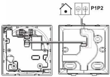
From the rear
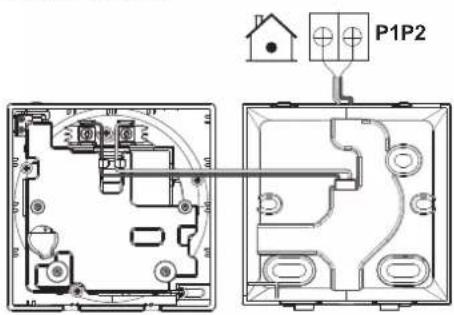
From the left
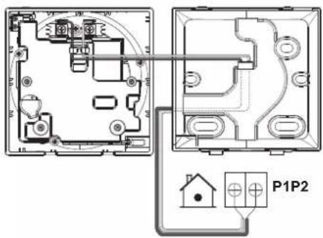
From the bottom
11.4 Closing the controller
11.4.1 Precautions when closing the controller

CAUTION
Never touch the internal parts of the controller.

CAUTION
When closing the controller, be careful not to pinch the wiring.

NOTICE
To prevent damage, make sure the front of the controller is clicked into the rear casing securely.
11.4.2 To close the controller
1 Click the front of the controller into the rear casing.
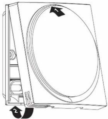
natural_image
Technical line drawing of a mechanical component with circular and rectangular features, no visible text or symbols2 When the installation site is dust-free, peel off the protective seal.
11.5 Opening the controller
11.5.1 Precautions when opening the controller

NOTICE
The controller PCB is mounted into the front casing. When opening the controller, be careful not to damage the PCB.

NOTICE
When the front and rear casing are separated, make sure the PCB does not come into contact with dust or moisture.
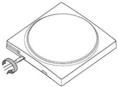
11.5.2 To open the controller
1 Insert a flat-head screwdriver into one of the bottom closing mechanisms and slowly twist it.
12 Starting up the system
natural_image
Line drawing of a square electronic device with a circular top and a small metallic connector attached (no text or symbols)12 Starting up the system

CAUTION
Before starting up the system, make sure:
- The indoor and outdoor unit wiring is completed.
- The switch box covers of the indoor and outdoor units are closed.
The controller gets its power from the indoor unit. It will start up as soon as it is connected. For the controller to be operable, therefore make sure the indoor unit is powered on.
Once the controller is powered, it will automatically start up. If it is the first and only controller that is connected to the indoor unit, it will automatically get designated as master controller. For a second controller to get designated as slave controller, manual action is required. For instructions, see "12.2 To designate a controller as slave" on page 12.
12.1 Master and slave controller
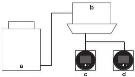
flowchart
graph TD
    A["a"] --> B["b"]
    B --> C["c"]
    B --> D["d"]
a Outdoor unit
b Indoor unit
c Master remote controller
d Slave remote controller
On the information screen, master/slave status is indicated by the following icons:
| Icon Description | |
| Master | |
| Slave | |
For more information, see "13.4.1 Information screen" on page 13.

INFORMATION
It is only possible to use a master and a slave controller of the same type.

INFORMATION
In case digital input adapter BRP7A5* is part of the system, it is not possible to connect and designate a second controller. Connecting a second controller when the system already contains the adapter, will cause the adapter to go in error.

INFORMATION
If a slave controller does not display the home screen 2 minutes after its designation, turn off the power and check the wiring.

INFORMATION
After re-designating a controller, the system requires a power reset.

INFORMATION
The following functions are not available for slave controllers:
- "Auto" operation mode
- Individual airflow direction
- Filter auto clean
- Setback temperature setpoints
- Draught prevention
- Duty rotation
12.2 To designate a controller as slave
Prerequisite: A master controller is already connected to the indoor unit.
1 Connect a second controller.
Result: It will start up automatically.
2 Wait for a U5 or U8 error to appear on the screen.

3 When the U5 or U8 error appears, press pressed until "2" appears on the screen.

Result: The controller is now designated as slave.

INFORMATION
If the slave controller does not display the home screen two minutes after its designation, turn off the power and check the wiring.
13 Operation
13.1 Buttons
a ON/OFF
- When OFF, press to turn ON the system. As a result, the status indicator (e) will turn ON too.
- When ON, press to turn OFF the system. As a result, the status indicator (e) will turn OFF too.
b ENTER/ACTIVATE /SET
- From the home screen, enter the main menu.
- From the main menu, enter one of the submenus.
- From their respective submenu, activate an operation/ventilation mode.
- In one of the submenus, confirm a setting.
c — CYCLE/ADJUST
- Cycle left.
- Adjust a setting (default: decrease).
d + CYCLE/ADJUST
- Cycle right.
- Adjust a setting (default: increase).
INFORMATION
The behaviour of the status indicator is according to field settings. For more information, see "14.1.3 Status indicator settings" on page 15.
13.2 Screen
Home screen
Depending on installer configuration, the controller either has a standard or a detailed home screen. In most cases, the standard home screen gives you only the active operation mode, messages (if any), and the setpoint temperature (in case of Cooling, Heating, or Auto operation mode). The detailed home screen gives you all kinds of information through status icons.
a Messages
b Active operation mode
c Setpoint temperature
Home screen mode is set with remote controller field setting R1-7 (Home screen). For more information, see "Remote controller field settings" on page 19.
Backlight
The screen backlight has the following states:
| State Description | |
| ON For the controller to be operable, the screen backlight needs to be ON (otherwise the controller does not detect any button presses). To turn ON the backlight, press ⬇ shortly.For instructions on how to set screen brightness and contrast when the backlight is ON, see "14.1.2 Screen settings" on page 14. | |
| • OFF• ON faintly | After a period of operation inactivity, the backlight will either turn OFF, or go into a faint ON state, depending on operation conditions:• Operation OFF: backlight OFF,• Operation ON: backlight ON faintly.Backlight state changeover after inactivity is set with remote controller field setting R1-8 (No-operation timer). Backlight faintness is set with remote controller field setting R1-10 (Backlight faintness). For more information, see "Remote controller field settings" on page 19. |
13.3 Status indicator
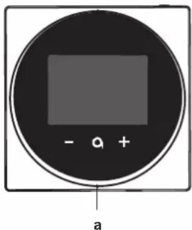
natural_image
Circular device with a black panel and control buttons, labeled 'a' at the bottom (no text or symbols on the device itself)a Status indicator
For instructions on how to make status indicator settings, see "14.1.3 Status indicator settings" on page 15.
13.4 Information
13.4.1 Information screen
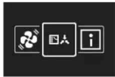
The information screen collects the following information:
| Information | Description |
| Software version | The information screen will always contain the latest software version.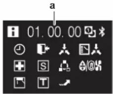 a Software version a Software version |
14 Configuration
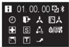
| Information Description |
Status icons Depending on operation status,the information screen can contain various status icons. For the meaning of those icons, see "5 Status icons" on page 5.When the information screen has information to convey,isdisplayed in the top left corner of the home screen.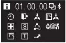 |

INFORMATION
The presence of icons on the information screen depends on operation status. The controller may display more or less icons than are indicated here.
To enter the information screen
Prerequisite: The controller displays the home screen.
1 Press a keep it pressed until the information screen appears.

INFORMATION
The presence of icons on the information screen depends on operation status. The controller may display more or less icons than are indicated here.
13.4.2 Information menu
You can consult additional information in the information menu, which is part of the installer menu. For instructions on how to enter the information menu, see "14.1 Installer menu" on page 14 and "Information" on page 27.
14 Configuration
14.1 Installer menu
14.1.1 About the installer menu
In the installer menu you can make the following settings:
| Category Icon Settings | ||
| Screen settings Brightness |  | |
 | Contrast | |
| Status indicator settings Inten |  |
| Category Icon Settings | ||
| Field settings Indoor unit field |  | |
 | Remote controller field settings | |
| Miscellaneous settings |  | Group address and AirNet address |
 | External input interlock | |
 | Force fan ON | |
 | Switch Cooling/Heating master | |
 | Information |
To enter the installer menu
Prerequisite: The controller displays the home screen.
1 Press a keep it pressed until the information screen appears:

INFORMATION
The presence of icons on the information screen depends on operation status. The controller may display more or less icons than are indicated here.
2 From the information screen, press — and Ⓞ simultaneously and keep them pressed until you enter the installer menu:
Result: You are now in the installer menu.
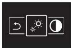
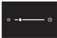
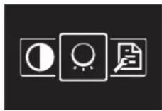
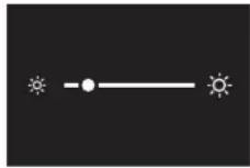
14.1.2 Screen settings
To set screen brightness
Prerequisite: You are in the installer menu. 1 Navigate to the screen brightness menu.
2 Use


ust screen brightness.
3 Press

onfirm.
Result: The screen adjusts its brightness and the controller returns to the installer menu.
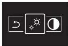
To set screen contrast
Prerequisite: You are in the installer menu.
1 Navigate to the screen contrast menu.
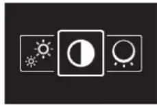
2 Use


ust screen contrast.
3 Press

onfirm.
Result: The screen adjusts its contrast and the controller returns to the installer menu.
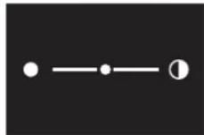
14.1.3 Status indicator settings
About status indicator settings
In the installer menu, you can set status indicator intensity and behaviour.
Intensity
For instructions on how to set status indicator intensity, see "To set status indicator intensity" on page 15.
Behaviour
Status indicator behaviour is changed through remote controller field settings. For instructions on how to make field settings, see "14.1.4 Field settings" on page 15. For an overview of remote controller field settings, see "Remote controller field settings" on page 19.
To set status indicator intensity
Prerequisite: You are in the installer menu.
1 Navigate to the status indicator intensity menu.
2 Use

to + just status indicator brightness.
3 Press

onfirm.
Result: The status indicator adjusts its intensity and the controller returns to the installer menu.
14.1.4 Field settings
About field settings
The controller allows for making field settings related to the indoor unit, and to the controller itself.
| Screen Field settings | |
| Indoor unit | |
| Remote controller | |
In both case, the setting procedure is the same. For instructions, see "Setting procedure" on page 15.
Setting procedure
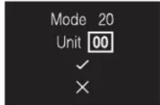
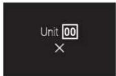
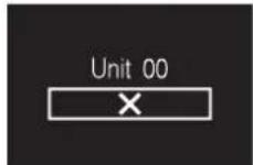
Field settings are composed of the following components:
1 Modes ("Mode"),
2 Units ("Unit"),
3 Settings ("SW"), and
4 Values for those settings.
The field settings menus have two levels. You set modes and units in the first level, and settings and values in the second.
14 Configuration
Level Description
First level Mode (Mode)
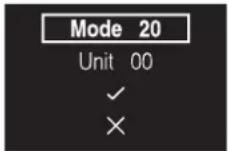
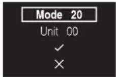
A mode is a group of settable parameters.
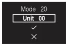
In the field settings tables, find available mode numbers in the "Mode" column. Mode numbers that apply to individual indoor units are between brackets in the "Mode" column.
Unit (Unit) (indoor unit field settings only)
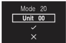
A unit is an individual unit to which a setting might apply.
When making field settings for individual units, this is the place where you define the number of the unit to which the setting applies.
When making field settings for grouped units, you do NOT set the unit number. The settings will then apply to all indoor units that are part of that group.
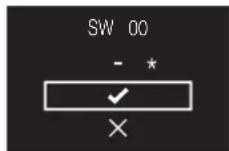
Second level Setting (SW)
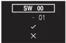
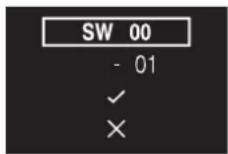
A setting is a settable parameter. These are the settings you are making.
In the field settings tables, find the available setting numbers in the "SW" column.
Value
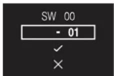
A value is one of a fixed set of values that you can choose for a setting.
When the value field contains a "-" , there are no values available for the selected setting:
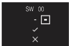
When making group settings, you can ONLY set a value for a setting if the value field contains a "*" (if the value field does NOT contain a "*", you cannot apply the selected setting to the group):

In the field settings tables, find the available values for each setting in the "Value" column.
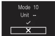
Navigation
1 Use


ve the highlighter.
To navigate through the field settings menus, use


2 Press to select a field setting component.
3 Use a to change the value of that field setting component.
4 Press to confirm that value.
5 In the first level, select to move to the second level.
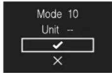
6 In the second level, navigate and select in the same way as you did in the first level.
7 Select to confirm and activate made settings.
8 At all times, select to go back a level.
Indoor unit field settings
The setting procedure is different depending on whether you want to make settings for individual units, or for grouped units.
Individual indoor units
- Define a mode by setting a Mode number (number between brackets)
- Define the unit to which the setting will apply by setting a Unit number
- Define the setting by setting a SW number
- Define a value for that setting
Grouped indoor units
- Define a mode by setting a Mode number (number NOT between brackets)
- Do NOT set a Unit number (setting applies to all the units in the group)
- Define the setting by setting a SW number
- Define a value for that setting
| Mode SW Setting (SW) description — | |||||||||
| 01 02 03 04 | |||||||||
| 10 (20) 00 | Filter contamination timer: set the timer for the appearance of the "Time to clean filter" screen. | Ultra long life filter | Light | ±10000 hrs. | Heavy | ±5000 hrs | — | — | |
| Long life filter | ±2500 hrs | ±1250 hrs | |||||||
| Standard filter | ±200 hrs | ±100 hrs | |||||||
| 01 | Long life filter: if applicable, set which type of long life filter is used. | Long life filter | Ultra long life filter | — | — | ||||
| 02 Controller thermostat sensor: set how the controller thermostat sensor is used. | Used in combination with indoor unit thermistor | Not used | Used exclusively | — | |||||
| 03 | Disable filter sign: set whether or not the filter sign can be displayed. | Display | Do not display | — | — | ||||
| 11 (21) 00 Simultaneous operation: set the simultaneous indoor unit operation mode (Sky Air) | Pair | Twin | Triple Double twin | ||||||
| 12 (22) 01 | External On/OFF input: set the operation of voltage free contacts T1/T2 (indoor unit contacts) | Forced OFF | On/OFF operation | Emergency | Forced OFF (multi-tenant) | ||||
| 02 Thermostat differential: if the system contains a remote sensor, set the increase/decrease increments. | 1°C | 0.5°C | — | — | |||||
| 13 (23) | 00 | High air outlet velocity: set in case of high-ceiling applications. | h≤2.7 m | 2.7 m<h≤3 m | 3 m<h≤3.5 m | ||||
| 01 Airflow direction: set in case an indoor unit is equipped with an option kit that blocks the airflow. | 4-way flow | 3-way flow | 2-way flow | — | |||||
| 03 Airflow function: set whether the indoor unit is equipped with a decoration panel at its air outlet. | Equipped | Not equipped | |||||||
| 04 | Airflow direction range | Upper | Normal | Lower | — | ||||
| 06 External static pressure: set the external static pressure (according to the resistance of the connected ducts). | Normal | High static pressure Low static pressure | — | ||||||
| 15 (25) 03 Humidification drain pump: set whether the system is equipped with a humidification drain pump. | Equipped | Not equipped | — | — | |||||
| 1c | 01 | Thermostat sensor: set which thermostat sensor you want to use. | Indoor unit thermistor | Controller thermistor | — | — | |||
| 1c | 12 | Window contact B1 (external input) | Do not use | Use | |||||
| 1c | 13 | Key card contact B2 (external input) | Do not use | Use | |||||
| 1e | 02 | Setback function: set Setback operation. | No Setback | Heating only | Cooling only | Heating and Cooling | |||
| 1e | 07 | Rotation overlap time. Set the Rotation overlap time. | 30 minutes | 15 minutes | 10 minutes | 5 minutes | |||
| 1B | 08 | Daylight saving time. Set how the system controls daylight saving time. | Disable | Automatic changeover | Manual changeover | Centralised control | |||

INFORMATION
- The connection of optional accessories to the indoor unit might cause changes to some field settings. For more information, see the installation manual of the optional accessory.
- For details about the specific field settings of each type of indoor unit, see the installation manual of the indoor units.
- Field settings that are not available for a connected indoor unit are not displayed.
- Field setting default values are different depending on the indoor unit model. For more information, see the service manual of the indoor units.
Remote controller field settings
| Mode SW SW description Value | Default value | ||||
| R1 3 Controller thermistor adjustment (Cooling) | 0: -3.0°C, 1: -2.5°C,2: -2.0°C, 3: -1.5°C,4: -1.0°C, 5: -0.5°C,6: ±0°C, 7: +0.5°C,8: +1.0°C, 9: +1.5°C,10: +2.0°C, 11: +2.5°C,12: +3.0°C | 6 | |||
| 4 Controller thermistor adjustment (Heating) | 0: -3.0°C, 1: -2.5°C,2: -2.0°C, 3: -1.5°C,4: -1.0°C, 5: -0.5°C,6: ±0°C, 7: +0.5°C,8: +1.0°C, 9: +1.5°C,10: +2.0°C, 11: +25°C,12: +3.0°C | 6 | |||
| 5 Controller thermistor adjustment (Auto) 0: -3.0°C | 1: -2.5°C,2: -2.0°C, 3: -1.5°C,4: -1.0°C, 5: -0.5°C,6: ±0°C, 7: +0.5°C,8: +1.0°C, 9: +1.5°C,10: +2.0°C, 11: +2.5°C,12: +3.5°C | 6 | |||
| 6 Controller thermistor adjustment (Fan only) | 0: -3.0°C, 1: -2.5°C,2: -2.0°C, 3: -1.5°C,4: -1.0°C, 5: -0.5°C,6: ±0°C, 7: +0.5°C,8: +1.0°C, 9: +1.5°C,10: +2.0°C, 11: +1.5°C,12: +3.5°C | 6 | |||
| 7 Home screen 0: Detailed | 1: Standard | 1 | |||
| 8 Backlight no-operation timer 0: 5 seconds | 1: 10 seconds2: 20 seconds | 0 | |||
| 9 Status indicator faintness 0: 0% (OFF), 1: 1%, | 2: 2%, 3: 3%,4: 5%, 5: 7%,6: 9%, 7: 11%,8: 13%, 9: 15%,10: 17%, 11: 20% | 9 | |||
| 10 Backlight faintness 0: 0% (OFF), 1: 1%, | 2: 2%, 3: 3%,4: 4%, 5: 5%, | 5 | |||
| 11 Status indicator mode 0: Normal | 1: Hotel setting 12: Hotel setting 2 | 2 | |||
| 13 Bluetooth Low Energy advertising 0: Always advertising | 1: Enable manually | 0 | |||
| R2 1 Touch button indicator (on screen) 0: None | 1: Small2: Medium3: Large | 1 | |||
Status indicator mode (R1-11)
Remote controller field setting R1-11 allows for the status indicator to be set to a mode suitable for use in hotels. According to the value that is set for this setting, the status indicator has the following behaviour:
| Operation state | Status indicator behaviour | ||
| 0 (Normal) | 1 (Hotel setting 1) | 2 (Hotel setting 2) | |
| Operation ON | ON | ON | ON (when the backlight goes into faint state, the status indicator turns OFF) |
| Operation OFF | OFF | OFF | OFF |
14 Configuration
| Operation state Status indicator behaviour | |||
| 0 (Normal) 1 (Hotel setting 1) 2 (Hotel setting 2) | |||
| Error Blinking (no change) (no change) | |||
| Warning ON ON ON (when the backlight goes into | faint state, the status indicator turns OFF) | ||
| Setting of status indicator intensity ON ON ON | |||
| Pairing with indoor unit Blinking Blinking Blinking | |||
14.1.5 Miscellaneous settings
Group address and Airnet address (DIII)
Group address
To control the system with central control equipment, you need to set addresses for:
- Groups ("Group"), and/or
- Units ("Group(Unit)").
The Group address and Airnet address menu has two levels. You define groups and/or units in the first level, and set or release addresses for those groups and/or units in the second.
| Address | Description |
| First level | Group (Group)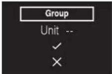 A group is a group of indoor units.When setting addresses for groups, you do NOT have to define a unit number. A group is a group of indoor units.When setting addresses for groups, you do NOT have to define a unit number. |
Unit (Group(Unit))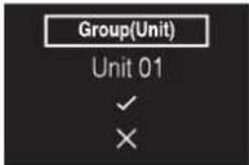 A unit is an individual indoor unit.Define the indoor unit for which you want to set an address. A unit is an individual indoor unit.Define the indoor unit for which you want to set an address.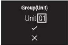 | |
| Address Description | |
| Second level Define an address for the indoor unit. | 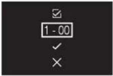 To SET an address, make sure selected. To SET an address, make sure selected.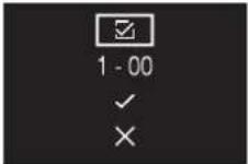 Apply settings. Apply settings.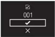 To RELEASE an address that was previously set, change a then apply settings. To RELEASE an address that was previously set, change a then apply settings.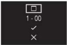 |
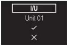
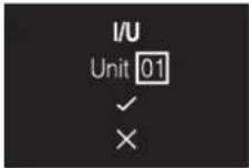
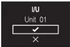
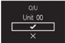
AirNet address
To connect the system to the AirNet monitoring and diagnostics system, you need to set AirNet addresses for:
- Indoor units ("I/U")
- Outdoor units ("O/U")
The Group address and AirNet address menu has two levels. You define groups and/or units in the first level, and set and release an address for those groups and/or units in the second.
14 Configuration
| Address Description | |
| First level Indoor unit (I/U) | |
 Define the indoor unit for which you want to set an AirNet address. Define the indoor unit for which you want to set an AirNet address. | |
 Proceed to the next level. Proceed to the next level. | |
 | |
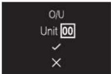
| Outdoor unit (O/U) | |
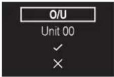 Define the outdoor unit for which you want to set an AirNet address. Define the outdoor unit for which you want to set an AirNet address. | |
 | |
 Proceed to the next level. Proceed to the next level. | |
| Second level Define an address for the indoor/outdoor unit. | 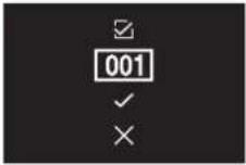 |
| To SET an address, make sure selected. | |
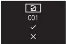 | |
| Apply settings. | |
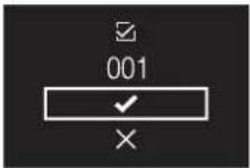 | |
| To RELEASE an address that was previously set, change then apply settings. | |
 |
External input interlock
About external input interlock
External input interlock allows for the integration of key card and window contact logic into the system.
External input interlock is only available in case digital input adapter BRP7A5* is part of the system. When the adapter is part of the system:
- it is not possible to connect a second (slave) controller, and
- the schedule function will be disabled for as long the adapter is connected to the indoor unit.
Make sure that the digital input adapter and its optional contacts (window contact B1 and key card contact B2) are correctly installed. Confirm that the voltage free contact of the digital input adapter is in the correct position. For instructions on how to install the digital input adapter, see the installation manual of the digital input adapter. In case the digital input adapter does not function properly, the external input interlock menu is not available in the installer menu. In case a centralised controller is additionally part of the system, external input interlock is controlled by the centralised controller. The digital input adapter is then overruled.
To make external input interlock settings
Prerequisite: You are in the installer menu.
External input interlock settings overview
1 Navigate to the external input interlock menu.
2 Use a-1 to +vigate through the menu.
3 Press to select a parameter.
4 With a parameter selected, use - and + to change that parameter's value.
5 With a parameter selected, press ☐ confirm the value for that parameter.
6 When you are done making settings, confirm all settings by selecting √nd pressing .
Result: The system will restart and implement any changes made.

INFORMATION
For an overview of settable parameters and what they mean, see "External input interlock settings overview" on page 23.
| Parameter Description | Possible values Default value | ||
B2 Delay Timer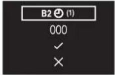 | Timer that starts as soon as the key card is removed. The unit continues normal operation until the timer expires. | 0-10 minutes | "1 min" |
14 Configuration
| Parameter Description | Possible values Default value | ||
| B2 Reset Timer Timer that starts as soon as the Delay Timer expires. When this timer expires, the previous state (i.e. regular setpoint) changes to the "Default Reset Setting" state. | 0-20 hours "20 hours" | ||
| Reset ON/OFF "Default Reset Setting" on/off state | "ON", "OFF", "--" "OFF" | ||
| Reset Mode "Default Reset Setting" operation mode | Auto, Cooling, Heating, Fan only, -- | "--" | |
| Reset Cool SP "Default Reset Setting" cooling setpoint | See indoor unit's setpoint range and setpoint range limitation, "--" | "22°C" | |
| Reset Heat SP "Default Reset Setting" heating setpoint | See indoor unit's setpoint range and setpoint range limitation, "--" | "22°C" | |

INFORMATION
When the value for a parameter is "- -", this means that when the timers expires, nothing changes for that parameter and the current active value is kept.
Window contact logic
| Window contact B1 Key card contact B2 Time Action | |||
| Contact closed (window open) Contact closed (key card IN) — Normal indoor unit operation. | The unit returns to the previous state before opening the contact. | ||
| Contact open (window open) | Contact closed (key card IN) — Unit operation is forced off: | No delay and reset timer functionality.No Setback functionality.Not possible to turn on/off the unit with the controller's ON/OFF button. | |
Key card contact logic
| Window contact B1 Key card contact B2 Time Action | |||
| Contact closed (window closed) Contact closed (key card IN) • — | Delay timerReset timer | The unit operates normally.If the reset timer has not expired, the unit returns to the previous state before opening the contact.If the reset timer has expired, the unit returns to the "Default Reset Setting" (see "External input interlock settings overview" on page 23). | |
| Contact closed (window closed) Contact open (key card OUT) TimeDay timer Normal indoor unit operation. | |||
| Contact closed (window closed) Contact open (key card OUT) Time>Day timer Unit operation is forced off: | Depending on whether the Setback function is enabled, Setback will work or not.Not possible to turn on/off the unit with the controller's ON/OFF button.After the delay timer has expired, the reset timer will start counting. | ||

INFORMATION
- The "previous state" can be the on/off state, operation mode, cooling setpoint, and heating setpoint.
- When using the contacts, the fan speed as well as the Setback cooling and heating setpoints can be changed at any time, without losing changes.
- The fan speed is stored independently for the two main operation modes (Heating and Cooling). Separate fan speed settings are saved for Heating operation mode on the one hand, and Cooling, Dry and Fan only operation mode on the other hand.
- When closing the contact, changes made while the key card contact is open and the delay timer has not expired (normal operation) will not be saved.
Combination of window contact and key card contact logic
- The window contact has priority over the delay timer and the Setback functionality of the key card contact: When the window contact is opened while the key card contact is open, the delay timer will immediately expire if it is still running, and Setback will not work anymore. The reset timer will immediately start counting or will not reset when it was already running.
- The reset timer functionality of the key card contact has priority over the window contact when returning to the previous state: When the key card contact is opened while the window contact is open, the delay timer will start running. When the delay timer expires the reset timer will start running. When the reset timer expires, the previous state is updated to the "Default Reset Setting" state.
Example 1
1 You remove the key card.
Result: The indoor unit continues operating normally until the delay timer expires.
2 You open the window before the delay timer expires.
Result: The indoor unit stops immediately. It is not possible to turn the unit on or off, the Setback functionality does not work, the delay timer stops counting, and the reset timer starts counting.
3 You insert the key card again.
Result: An update of the previous state occurs. The unit is forced off and the Setback functionality is still disabled (see "Window contact logic" on page 24).
IF the reset timer HAS NOT expired before inserting the key card, the previous state is the same as the original state because there was only a change to the original state.
IF the reset timer HAS expired before inserting the key card, the previous state is the "Default Reset Setting" state.
4 You close the window.
Result: The unit reverts to the previous state. The previous state depends on the expiration of the reset timer.
Example 2
1 You open the window.
Result: The unit stops immediately. It is not possible to turn the unit on or off with the ON/OFF button, the Setback functionality does not work, and the delay timer does not start counting.
2 You remove the key card.
Result: The delay timer starts counting.
3 You close the window again.
Result: There is no change in state. It is as if you never opened the window (Setback will work if enabled).
IF the delay timer HAS expired before closing the window, the reset timer will have started counting. Closing the window has no influence on the reset timer.
IF the delay timer HAS NOT expired before closing the window, it will expire immediately and the reset timer will start counting. When the reset timer expires, the previous state is updated to the "Default Reset Setting" state.
4 You insert the key card again.
Result:
IF the reset timer HAS NOT expired before inserting the key card, the unit returns to the state before the window was opened (last "on" state);
IF the reset timer HAS expired before inserting the key card, the unit goes to the "Default Reset Setting" state.
14 Configuration
Force fan ON
About Force fan ON
Force fan ON allows you to force fan operation of individual indoor units. In this way, you can check which indoor unit number was assigned to which indoor unit.
To force fan operation
Prerequisite: You are in the installer menu.
1 Navigate to the Force Fan ON menu.
2 Select an indoor unit number.
3 Select and press to voice fan operation.
Result: The fan of the indoor unit that corresponds to the selected indoor unit number starts operating.
Switch Cooling/Heating master
About Cooling/Heating masterhood
A
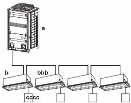
flowchart
graph TD
    A["Server Unit a"] -->|b| B["CC"]
    A -->|b| C["bbb"]
    A -->|ccc| D["ccc"]
    A -->|ccc| E["ccc"]
B
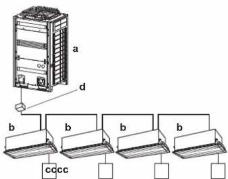
A Heat pump system
B Heat recovery system
a Outdoor unit
b Indoor unit
c Remote controller
d BS unit
When multiple indoor units are connected to the same outdoor unit, there are restrictions as to the operation modes in which they can run. One outdoor unit does not allow for one indoor unit to perform Cooling operation, while another performs Heating operation.
Therefore, the system requires that one indoor unit is set as cooling/heating master. This indoor unit then decides the operation modes in which the other (slave) indoor units can run. When one indoor unit is set as cooling/heating master, the other indoor units automatically become its slaves. For instructions, see "To set Cooling/Heating masterhood" on page 26.
Cooling/Heating masterhood corresponds to the following status icon:
The behaviour of this status icon is according to the following table:
| If a controller displays ... Then ... | |
| ... NO status icon ... The indoor unit connected to that controller is Cooling/Heating master. | |
| ... a CONSTANT status icon ... The indoor unit connected to that controller is slave to a Cooling/Heating master. | |
| ... BLINKING status icon | ... NO indoor unit is assigned as Cooling/Heating master yet. |
The operation mode behaviour of the indoor units is according to the following table:
| If the master ... | Then the slaves ... |
| ... is set to "Heating", "Dry", or "Auto" operation mode | ... start running in the same operation mode as the master. No other modes are then available for them. |
| ... is set to "Cooling" operation mode | ... then the slaves cannot run in "Heating" operation mode, but can still run in "Cooling", "Fan only" and "Dry" operation mode. |
| ... is set to "Fan only" mode | ... can ONLY run in "Fan only" mode. |
Once an indoor unit is set as master, it can be released from masterhood. For instructions, see "To release Cooling/Heating masterhood" on page 27.
To set Cooling/Heating masterhood
Prerequisite: No indoor unit is yet set as Cooling/Heating master ("changeover under centralised control" icon blinking on all controllers).
Prerequisite: You are operating the controller of the indoor unit that you want to set as Cooling/Heating master.
1 Navigate to the operation mode menu.
2 Set the operation mode to either Cooling or Heating.
Result: The indoor unit is now Cooling/Heating master ("changeover under centralised control" icon not on controller).
Result: All slave controllers display the "changeover under centralised control" icon.
To release Cooling/Heating masterhood
Prerequisite: You are in the installer menu.
Prerequisite: You are operating the controller of the indoor unit that you want to release from its masterhood.
1 Navigate to the Cooling/Heating masterhood menu.
2 Press t+lease the indoor unit from its masterhood.
Result: The indoor unit is released from its masterhood.
Result: The controllers of all indoor units display a blinking "changeover under centralised control" icon.
Information
About the information menu
In the information menu, you can find the following information:
| Information Description | |
| SW1 Controller software ID | |
| Ver Controller software version | |
| Time | |
| SW2 UE878 software ID | |
| --:--:--:--:--:--: UE878 MAC address | |
To read out information
Prerequisite: You are in the installer menu.
1 Navigate to the information menu.
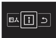
2 Read out information.
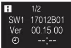
3 Press t+go to the second page.
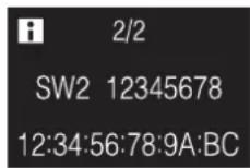
14.2 Remote controller software update
14.2.1 To update the software with Updater
Prerequisite: PC with Updater (contact your dealer for the correct version of the software)
Prerequisite: PC USB cable EKPCCAB4 or higher (includes a USB cable and additional connection cables)
1 Make sure that the indoor unit is powered OFF.
2 Connect the controller to the PC.
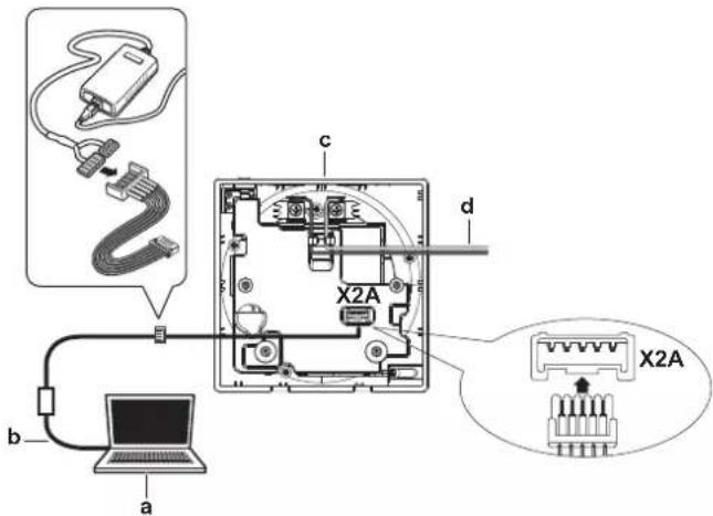
a PC with Updater
b USB cable
c Controller PCB
d To indoor unit
3 Power ON the indoor unit.
4 Open Updater.
5 In Updater, go to "Update procedure".
6 Type in the model name of the controller.
7 Select the desired update procedure.
8 Follow the on-screen instructions.
15 About the app
The Madoka Assistant app is a companion to the BRC1H remote controller. Where the controller only allows for basic operation and configuration, the app offers advanced operation and configuration functionality.
15.1 Operation and configuration overview
The app continually searches for BRC1H controllers to connect with. All controllers that are in range of your mobile device are listed in the home menu.
To operate and/or configure the system, tap the tile of the controller that is connected to the indoor units that you want to control.
15.2 Pairing
15.2.1 About pairing
Before you can actually connect with a controller, you have to make sure that the app and the controller are paired. Pair the app with all the controllers that you want to connect with.
15.2.2 To pair the app with a controller
Prerequisite: You are close to the controller.
1 In the app, tap the controller that you want to pair with.
Result: The operating system of your mobile device sends out a pairing request.
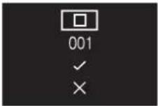
Result: The controller displays the following screen:

2 In the app, accept the pairing request.
3 On the controller, accept the pairing request by pressing

Result: The app is paired with the controller.

INFORMATION
Once paired with the app, the controllers will remain bonded. It is not required to repeat this procedure each time you want to use the app, unless you delete the bonds.
15.3 Installer mode
15.3.1 About installer mode
In installer mode you have access to settings that are not available for regular end users.
15.3.2 To activate Installer mode
Prerequisite: You are not in installer mode.
1 Go to the main menu.
2 Tap "About".
3 Tap "Application version" five times.
Result: You are in the installer mode menu.
Result: Installer mode is automatically activated.

INFORMATION
- To continue using the app in installer mode, tap the return button.
- The duration of installer mode depends on installer mode settings. For more information, see "15.3.4 To make Installer mode settings" on page 28.
- There is a visual indication that installer mode is active, which can be disabled. For more information, see "15.3.4 To make Installer mode settings" on page 28.
15.3.3 To deactivate Installer mode
Prerequisite: You are in installer mode.
1 Go to the main menu.
2 Tap "Installer mode enabled".
Result: You are in the installer mode menu.
Result: Installer mode is automatically activated.
3 Deactivate installer mode by tapping the slider.
Result: Installer mode is deactivated.
15.3.4 To make Installer mode settings
1 Enable installer mode.
Result: You are in the installer mode menu.
2 Make installer mode settings.
| Installer mode settings Description | |
| Installer mode activation Enable or disable installer mode. | |
| Installer mode duration timer Set the duration of installer mode.30 minutes: installer mode active for 30 minutes. After 30 minutes, installer mode will automatically deactivate.(default)Indefinitely: installer mode active until the next manual deactivation. | |
| Installer mode indicator Set whether installer mode activation is indicated by the installer mode indicator. |

INFORMATION
Mind that installer mode is automatically enabled as soon as you enter the installer mode menu.
15.4 Demo mode
15.4.1 About demo mode
To try out the app's operation and configuration functions in a safe environment, it is possible to launch a demo version of the app.
15.4.2 To launch demo mode
Prerequisite: You are not in demo mode.
1 Go to the main menu.
2 Tap "Demo mode".
Result: You are in demo mode.
15.4.3 To exit demo mode
Prerequisite: You are in demo mode.
1 Go to the main menu.
2 Tap "Exit demo mode".
Result: You exited demo mode.
15.5 Functions
15.5.1 Overview: Functions
From the operation screen, you can do the following:
| Category Control | |
| Operation Turn ON/OF unit operation | |
| Category Control | |
| Configuration and advanced operation | Make controller and indoor unit settings:GeneralRemote controller firmware updateNotificationsRemote controller settingsMaster/slave statusScreenStatus indicatorDate and timeAboutRemove bonding informationEnergy savingPresence detectionConfiguration and operationSetpoint modeSetbackIndividual airflow directionSetpoint rangeAirflow direction rangeDraught preventionMaintenanceErrors and warningsUnit numberFilter auto cleanAirNet addressGroup addressField settingsDuty rotationTest operation |
15.5.2 Remote controller firmware update
Update remote controller firmware. It is required to keep remote controller firmware up to date. When new firmware is available for a controller, the app will send out a notification in the operation screen of that controller.
To update remote controller firmware
Prerequisite: You are in the operation screen of one of the controllers, and the app notified you that new firmware for that controller is available.
Prerequisite: You are close to the controller.
1 Tap the settings icon.
Result: You are in the Unit settings menu.
2 At the very top, tap "Firmware update available".
Result: You are in the "Firmware update" menu.
3 Tap "Update firmware".
Result: The latest firmware is downloaded to the controller.
Result: During the download, the controller displays the following screen.
15 About the app
Result: After the download, the controller restarts to implement changes.
15.5.3 Notifications
Get an overview of active system notifications. These can be:
- Errors
- Warnings
- System information
15.5.4 Master/slave status
Find out if the controller you are operating is a master or a slave controller. It is not possible to make changes to master/slave status from the app. For instructions on how to change a controller's master/slave status, see "12 Starting up the system" on page 12.
15.5.5 Screen
Make remote controller screen settings:
| Setting Description | |
| Home screen mode Switch between | "Standard" or "Detailed" home screen mode. In "Detailed" mode, the remote controller gives extensive system operation through status icons, as compared to "Standard" mode. |
| Brightness Set screen brightness. | |
| Contrast Set screen contrast. |

INFORMATION
When making remote controller screen settings from the app, it is possible that the remote controller does not implement changes immediately. To make the controller implement changes: on the controller, navigate to the installer menu, and then back to the home screen. For instructions on how to enter the installer menu, see "To enter the installer menu" on page 14.
15.5.6 Status indicator
Make remote controller status indicator settings:
| Settings Description | |
| Mode Check the active status indicator | mode. It is not possible to set the status indicator mode from the app; this happens through remote controller field setting R1-11. For more information, see "Remote controller field settings" on page 19. |
| Intensity Set status indicator intensity. | |
15.5.7 Date and time
Set the remote controller date and time. In the date and time menu you send date and time information to the remote controller from the app. You can choose to either send the date and time information of your mobile device ("Synchronise"), or to manually create and send date and time information.

INFORMATION
If the controller is disconnected from the power for more than 48 hours, the date and the time need to be set again.

INFORMATION
The clock will maintain accuracy to within 30 seconds/month.
15.5.8 About
Read out the current remote controller and remote controller Bluetooth module software version.
15.5.9 Remove bonding information
Make the controller forget all previously bonded mobile devices.
15.5.10 Setpoint mode
Set whether the controller runs in "Indoor unit" or "Remote controller" setpoint mode.
| Setpoint mode | Description |
| Indoor unit The system uses indoor | or unit setpoint logic. |
| Remote controller | The setpoint logic is the same for Cooling and Heating operation. |

INFORMATION
- In "Remote controller" setpoint mode, there is one shared setpoint for Cooling and Heating operation mode. Changing the setpoint for Cooling operation automatically changes the setpoint for Heating operation.
- When the indoor units are under control of a centralised controller, only "Indoor unit" setpoint mode is possible.
15.5.11 Setback
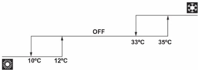
Enable Setback temperature control. Setback is a function that keeps the room temperature in a specific range when the system is turned off. To achieve this, the system temporarily runs in Heating or Cooling operation mode, according to the setback setpoint and recovery differential.
Example:
flowchart
graph TD
    A["Sun icon"] --> B["10°C"]
    B --> C["12°C"]
    C --> D["OFF"]
    D --> E["33°C"]
    E --> F["35°C"]
    F --> G["Warning icon"]
| Settings | Result | ||
| Heating operation | Setback setpoint | 10°C | If the room temperature drops below 10°C, the system automatically starts heating operation. If after 30 minutes the temperature rises above 12°C, the system stops heating operation, and turns off again. If the room temperature drops below 10°C again, the process gets repeated. |
| Recovery differential | +2°C | ||
| Settings Result | |||
| Cooling operation[AKSY] | Setback setpoint | 35°C If the room temperature rises above 35°C, the system automatically starts cooling operation. If after 30 minutes the temperature drops below 33°C, the system stops cooling operation, and turns off again. If the room temperature rises above 35°C again, the process gets repeated. | |
| Recovery differential | -2°C | ||

INFORMATION
- Setback is by default enabled.
- Setback turns on the system for at least 30 minutes, unless the setback setpoint is changed, or the system is turned on with the ON/OFF button.
- When Setback is active, you cannot make changes to fan speed settings.
- When Setback activates while the system is set to Auto operation mode, the system will switch to Cooling or Heating operation mode, depending on which is required. The Setback setpoint displayed on the operation screen is then according to the operation mode.

INFORMATION
This function cannot be used when the indoor units are controlled by a centralised controller.

INFORMATION
The default setpoint range limits for Setback operation are [33^-37^] for Cooling operation, and [10^-15^] for Heating operation. It is not possible to change these limits.
15.5.12 Individual airflow direction
Set the airflow direction of each individual indoor unit air outlet. The maximum number of indoor units for which you can make these settings depends on the type of system:
| System Maximum number of indoor units | |
| Sky Air 4 | |
| VRV 16 | |
Of cassette-type indoor units, it is possible to identify the individual air outlets by way of the following indicators:
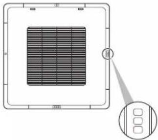
natural_image
Diagram of a solar panel array with a magnified inset showing three ports (no text or symbols)
INFORMATION
The availability of this function depends on the type of indoor unit.
15.5.13 Setpoint range
Set a limitation to the temperature setpoint range of both Cooling and Heating operation.

INFORMATION
This function cannot be used when the indoor units are controlled by a centralised controller.

INFORMATION
The default setpoint range limits for both Heating and Cooling operation is [16^-32^] , regardless of whether or not Setpoint range is enabled. It is not possible to exceed these limits.
15.5.14 Airflow direction range
Set the indoor unit airflow direction range according to the installation location. This function is available for floorstanding indoor units only. The maximum number of indoor units for which you can make these settings is 16.
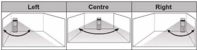
The ranges correspond with the following airflow swing patterns:
| Left | Centre | Right |
| Left swing | Wide swing | Right swing |

INFORMATION
The availability of this function depends on the type of indoor unit.

INFORMATION
For systems in which the indoor units run in simultaneous operation, it is possible to set the airflow direction range of individual indoor units by connecting the controller to each indoor unit separately.
15.5.15 Draught prevention
Prevent people from getting affected by indoor unit airflow, based on (the lack of) presence detected by a motion sensor.

INFORMATION
To use this function, it is required that the indoor units are equipped with a motion sensor (optional accessory).

INFORMATION
This function is not supported when the system contains Sky Air RR or RQ outdoor units.
15.5.16 Presence detection
Set a timer for the system to adjust the temperature setpoint or to turn off automatically, based on (the lack of) presence detected by a motion sensor.
| Action | Description |
| Auto OFF | Set an OFF timer that starts running as soon as the motion sensor detects the room is unoccupied. |
15 About the app
| Action Description | |
| Setpoint adjustment Set setpoint adjustment increments and intervals for both heating and cooling operation. When the motion sensor detects the room is unoccupied, the system will raise (cooling operation) or lower (heating operation) the setpoint, until the set limit is reached. | |

INFORMATION
To use this function, it is required that the indoor units are equipped with a motion sensor (optional accessory).

INFORMATION
This function cannot be used when the indoor units are controlled by a centralised controller.

INFORMATION
This function cannot be used when the indoor units are in group control.

INFORMATION
For systems in which the indoor units run in simultaneous operation, this function is controlled by the motion sensor mounted in the master indoor unit.
15.5.17 Errors and warnings
Consult the error history, and temporarily enable/disable the pushing of error and/or warning notifications.
The pushing of error and warning notifications is by default enabled. Disable "Display errors" and "Display warnings" to prevent the system from pushing error and warning notifications for 48 hours. After 48 hours, "Display errors" and "Display warnings" become automatically enabled again.
15.5.18 Unit number
Change the unit number of the indoor unit(s). To configure individual indoor units, these units require a unit number. The unit number of an indoor unit is its ranking in the list. To give a unit a new unit number, change its ranking by either moving it to an empty slot, or switching it with another indoor unit. If you need help identifying physical indoor units, tap an indoor unit's fan icon to make that indoor unit's fan operate.
15.5.19 Filter auto clean
Enable automatic indoor unit filter cleaning operation and set a timespan for it.

INFORMATION
To use this function, it is required that the indoor units are equipped with a self-cleaning decoration panel (optional accessory).
15.5.20 AirNet address
Assign AirNet addresses to the indoor and outdoor units, this to connect the system to the AirNet monitoring and diagnostics system. First select a unit by way of its unit number, then assign it an AirNet address.
15.5.21 Group address
Assign addresses to the indoor units, this to control the system with central control equipment. You can assign an address to the group of indoor units connected to the controller, and to indoor units individually.
15.5.22 Field settings
Make indoor unit and remote controller field settings. For an overview of possible field settings, see "Indoor unit field settings" on page 18 and "Remote controller field settings" on page 19.
Setting procedure
Field settings are composed of the following components:
- Modes
- Units
- Settings
- Values
The field settings procedure differs depending on whether you are making settings for individual indoor units or for groups of indoor units, or for the remote controller.
| Field settings type Procedure | |
| Individual indoor units • Set the field setting type to "Indoor unit".Define a mode. In the field settings table, find this number between brackets in the Mode column.Define the unit to which the setting will apply by setting a unit number.Define the setting by tapping the right tile in the app. In th field settings table, find settings in the SW column.Define a value for that setting. | |
| Groups of indoor units | • Set the field setting type to "Indoor unit".Define a mode. In the field settings table, find this number NOT between brackets in the Mode column.Do NOT set a unit number (the settings will apply to all units in the group).Define the setting by tapping the right tile in the app. In th field settings table, find settings in the SW column.Define a value for that setting. |
| Remote controller | • Set the field setting type to "Remote controller".Define a mode.Define the setting by tapping the right tile in the app. In th field settings table, find settings in the SW column.Define a value for that setting. |
Default values
Field setting default values are different depending on the indoor unit model. For more information, see the service manual of the indoor units. For the following field settings, the default values are the same for all indoor unit models:
| Field setting Default value | |
| Thermostat sensor 02 | |
| Setback 04 | |
| Window contact B1 02 | |
| Key card contact B2 02 | |
| Airflow direction range 02 | |
| Remote controller thermostat sensor | 02 |
| Rotation overlap time 03 | |

INFORMATION
- The connection of optional accessories to the indoor unit might cause changes to some field settings. For more information, see the installation manual of the optional accessory.
- For details about the specific field settings of each type of indoor unit, see the installation manual of the indoor units.
- Outdoor unit field settings can only be configured via the outdoor unit PCB. For more information, see the installation manual of the outdoor unit.
- Field settings that are not available for a connected indoor unit are not displayed.
15.5.23 Duty rotation
Activate Duty rotation to let the indoor units operate alternately (one indoor unit alternately inactive), this to increase system lifespan and reliability.
Duty rotation is designed for units operating in critical applications (e.g. in server rooms that require lots of cooling). In these cases, the system is equipped with an extra backup unit. Activating Duty rotation then allows for:
- Rotation: because the system is equipped with more units than are required to provide the heating/cooling load, one of the units can remain inactive during normal operation. After a set time (i.e. "Rotation cycle time"), the inactive unit will start operation, and a previously active unit will become inactive (i.e. duty rotation). Because the units only operate alternately, the lifespan of the system increases.
- Backup: having a backup unit allows for system redundancy. If an active unit goes into error, "Duty rotation" makes sure an inactive one takes over.
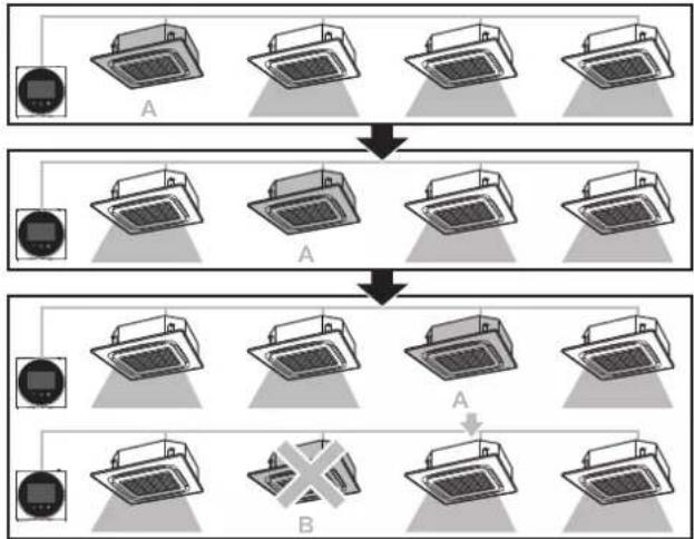
flowchart
graph TD
    A1["Light Lamp"] --> A2["A"]
    A2 --> A3["A"]
    A3 --> A4["A"]
    A4 --> A5["A"]
    A5 --> A6["A"]
    A6 --> A7["B"]
    style A1 fill:#f9f,stroke:#333
    style A2 fill:#f9f,stroke:#333
    style A3 fill:#f9f,stroke:#333
    style A4 fill:#f9f,stroke:#333
    style A5 fill:#f9f,stroke:#333
    style A6 fill:#f9f,stroke:#333
    style_B1["Light Lamp"] --> B2["A"]
    style B2 --> B3["A"]
    style B3 --> B4["A"]
    style B4 --> B5["A"]
    style B5 --> B6["A"]
A Inactive backup unit
B Unit in error

INFORMATION
This function can only be used when the indoor units are in group control.

INFORMATION
- To let the backup unit reach its cooling/heating capacity, an overlap period is included in which all indoor units are active. For more information, see "Indoor unit field settings" on page 18 (cfr. field setting 1E-7).
- The rotation order depends on the set unit number. For instructions on how to change the indoor units' unit number, see "15.5.18 Unit number" on page 32.
15.5.24 Test operation
Perform a test run on Sky Air indoor units. During the test run, the indoor units cycle through various operation modes and functions to check if they are ready for operation.
When
Only activate the test operation after the following is completed:
- Installation of refrigerant piping;
- Installation of drain piping;
- Connection of electrical wiring.
Typical workflow
Performing a test operation typically consists of the following stages:
1 Activating the test operation (Madoka Assistant app),
2 Testing the indoor unit functions according to the instructions set out in "To perform a test operation" on page 34,
3 Deactivating the test operation (Madoka Assistant app),
4 Checking the error history for possible errors.
5 If applicable, fixing the causes of those errors.
6 Repeating the procedure if required.

INFORMATION
Also see the installation manual of the indoor unit and outdoor unit.
Precautions when performing a test operation

CAUTION
Before starting up the system, make sure:
- The indoor and outdoor unit wiring is completed.
- The switch box covers of the indoor and outdoor units are closed.

NOTICE
Be sure to turn on the power 6 hours before operation in order to have power running to the crankcase heater and to protect the compressor.

INFORMATION
After the installation of the refrigerant piping, drain piping, and electrical wiring, make sure to clean the inside of the indoor unit, as well as the decoration panel.
To perform a test operation
1 Confirm that the indoor unit gas and liquid stop valves are open.

INFORMATION
It is possible that the pressure inside the refrigerant circuit does not rise, despite the opened stop valve. This can be due to the expansion valve (or the like) blocking the refrigerant, and does not obstruct the test run.
2 Open the Madoka Assistant app.
3 Navigate to the operation screen of the controller that is connected to the indoor unit(s) on which you want to perform a test run.
4 In the operation screen, set the operation mode to Cooling.
5 Go to the "Unit settings" menu (upper right corner of the operation screen).
Result: You are in the "Unit settings" menu.
6 In the "Maintenance field", tap "Test operation".
Result: You are in the "Test operation" menu.
7 Tap "Start test operation".
Result: The indoor unit(s) enter test operation mode, during which normal operation is not possible.
8 Return to the operation screen.
9 Tap "Vertical airflow direction".
10 Tap "Fixed"
11 Cycle through the five fixed airflow directions, and confirm if the indoor unit flaps behave correspondingly.
12 Return to the "Test operation" menu.
13 Tap "Stop test operation".
Result: The indoor units leave test operation mode. Normal operation is possible again.
14 Go to "6 Operation" on page 5 and confirm if the indoor unit(s) behave according to the information set out there.
15 Check the error history. If required, solve the cause of the errors and perform the test operation again.

INFORMATION
The test operation finishes after 30 minutes.
16 Maintenance
16.1 Maintenance safety precautions

WARNING
Before carrying out any maintenance or repair activities, stop system operation with the controller, and turn off the power supply circuit breaker. Possible consequence: electric shock or injury.

NOTICE
To clean the controller, do NOT use organic solvents, such as paint thinner. Possible consequence: damage, electric shock, or fire.

WARNING
Do not wash the remote controller. Possible consequence: electric leakage, electric shock, or fire.

INFORMATION
When the dirt on the surface cannot be removed easily while cleaning the controller, soak the cloth in neutral detergent diluted with water, squeeze the cloth tightly, and clean the surface. Afterwards, wipe dry with a dry cloth.
16.2 About maintenance
When the indoor unit needs to be maintained, the controller will display in the home screen, and confront you with a warning screen as soon as you try to enter the main menu. Perform the required maintenance, and then remove the warning screen.
The following warning screens are related to indoor unit maintenance:
Time to clean filter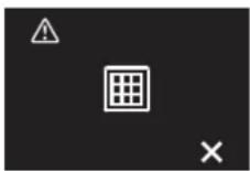 | Time to replace filter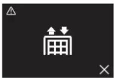 |
Time to empty dust collector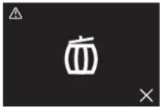 | — |
Time to empty dust collector
16.3 To remove a warning screen
Prerequisite: The controller displays the home screen, and is visible, indicating error or maintenance.
1 Press ☐ to enter the main menu.
Result: Since ▲ is visible, you are confronted with a warning screen, e.g.

2 Solve the cause of the warning screen.
3 Press +to remove the warning screen.
Result: The controller returns to the home screen. If the cause of the warning was properly solved, A has disappeared.
16.4 To clean the controller
1 Wipe the screen and other surface parts of the controller with a dry cloth.
17 Troubleshooting
17.1 Error codes of the indoor unit
When the indoor unit is in error, the controller will display a home screen, and confront you with an error screen as soon as you try to enter the main menu:
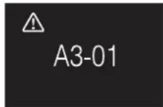
Solve the cause of the error, and press +b remove the error screen. For an overview of indoor unit error codes and what they mean, see the documentation of the indoor units.
18 Technical data
A subset of the latest technical data is available on the regional Daikin website (publicly accessible). The full set of latest technical data is available on the Daikin extranet (authentication required).
18.1 Connection diagram
18.1.1 Typical layout
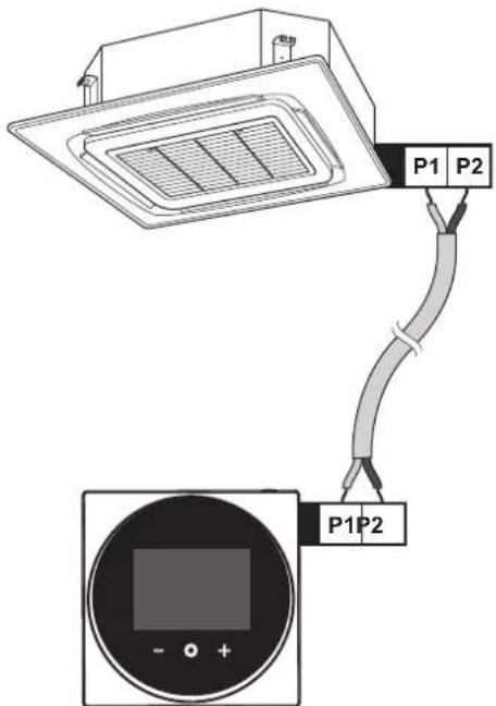
18.1.2 Typical layout for group control
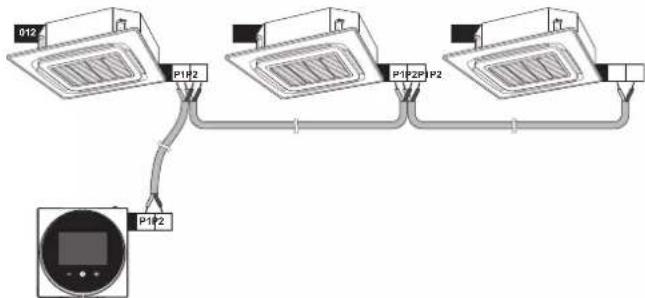
Group control: master and slave controller
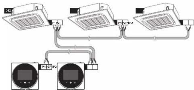
flowchart
graph TD
    A["012"] --> B["P1P2"]
    A --> C["P1P2P1"]
    A --> D["P2"]
    B --> E["P1P2P1"]
    C --> F["P2"]
    D --> G["Ground"]
Group control: controller + digital inputs adapter BRP7A5
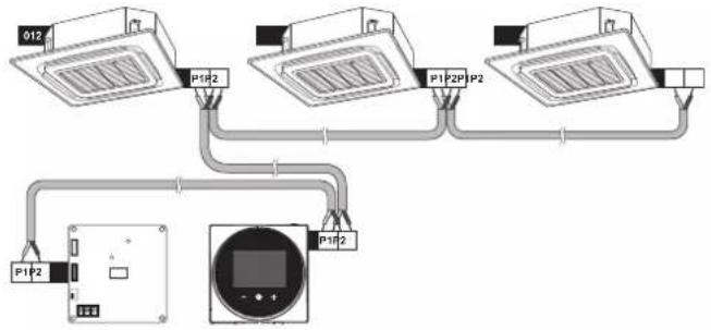
flowchart
graph TD
    A["012"] --> B["P1P2"]
    C["P1"] --> D["P2P1"]
    E["P2"] --> F["P2P2"]
    G["P1P2"] --> H["Display Unit"]
    I["P1P2"] --> H
    J["Ground"] --> H
18.1.3 Controller + DIII central control equipment
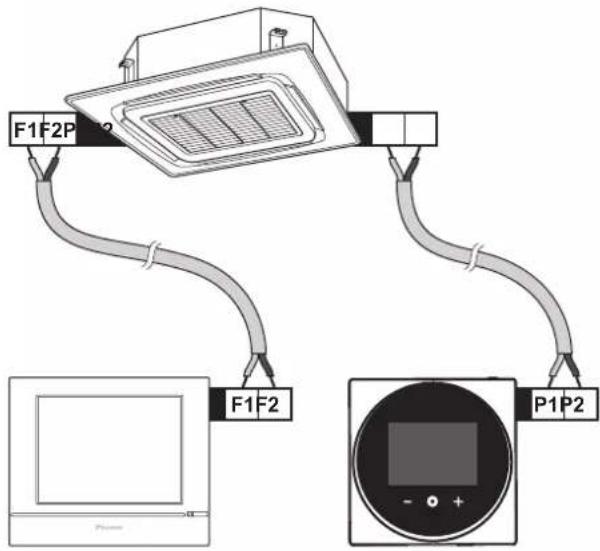


natural_image
Blank grid paper with no text, numbers, or symbols

natural_image
Blank grid paper with no text, numbers, or symbols
UA. TR. 028

TA-2017/3281
APPROVED
И005 18
Maximum Voltage: DC 17.6 V
Power Consumption: Max 1.94 VA
OMAN - TRA
TRA-TA-R/5107/18 D100428
TRC/LPD/2018/60