
BC 750 - Lawn mower STIGA - Free user manual and instructions
Find the device manual for free BC 750 STIGA in PDF.

| Product Type | Hand-held powered brushcutter (lawn trimmer) |
| Engine Type | 2-stroke, air-cooled |
| Displacement | 25.4 cc (approx) |
| Power Output | 1.0 kW (net) |
| Cutting Width | 38 cm (with blade) |
| Fuel Tank Capacity | 0.5 L (approx) |
| Fuel Mixture | Unleaded petrol + 2-stroke oil (ratio see manual) |
| Cutting Means Options | Nylon line head, 3/4/8-point blade, saw blade (if allowed) |
| Starting System | Manual recoil starter |
| Sound Pressure Level | 109.1 dB(A) (measured) |
| Sound Power Level (guaranteed) | 112 dB(A) |
| Vibration (front/rear handle) | Varies; see manual |
| Harness Type | Single strap, double strap, or backpack (model dependent) |
| Weight | 5.5 kg (approx) |
| Transmission Tube | Rigid or flexible (model dependent) |
| Guards | Specific guards for each cutting means |
| Maintenance Intervals | Every 15 hours (air filter), 30 hours (spark plug), etc. |
| Warranty | Coverage per national legislation |
| Compliance | CE, UKCA |
Frequently Asked Questions - BC 750 STIGA
User questions about BC 750 STIGA
0 question about this device. Answer the ones you know or ask your own.
Ask a new question about this device
Download the instructions for your Lawn mower in PDF format for free! Find your manual BC 750 - STIGA and take your electronic device back in hand. On this page are published all the documents necessary for the use of your device. BC 750 by STIGA.
USER MANUAL BC 750 STIGA
natural_image
Icon of a person reading a book inside a circle (no text or symbols)EN Hand-held powered brushcutter OPERATOR'S MANUAL
WARNING: read thoroughly the instruction booklet before using the machine.
MANUAL DE INSTRUÇÕES
MANUAL DE INSTRUCTIUNI

18

19

natural_image
Diagram of a mechanical device with a belt and directional arrow, labeled 'J' (no text or symbols beyond label)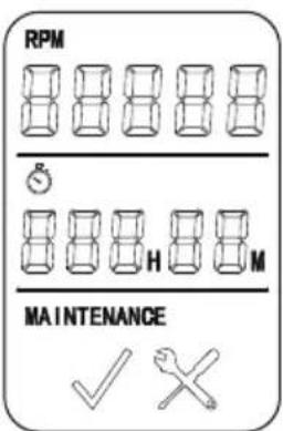
20


21

natural_image
Line drawing of hands using a tool to adjust or install a mechanical component (no text or symbols present)22

natural_image
Diagram of a person using a pulley system with motion arrows indicating airflow or vibration (no text or symbols)23
natural_image
Technical illustration showing mechanical components and a close-up of a grinding machine tool (no text or symbols present)The image contains no text or characters.
natural_image
Technical illustration of a mechanical device with gear and rotating components, showing motion paths (no text or symbols)


natural_image
Blank white image with no visible content, text, or symbols.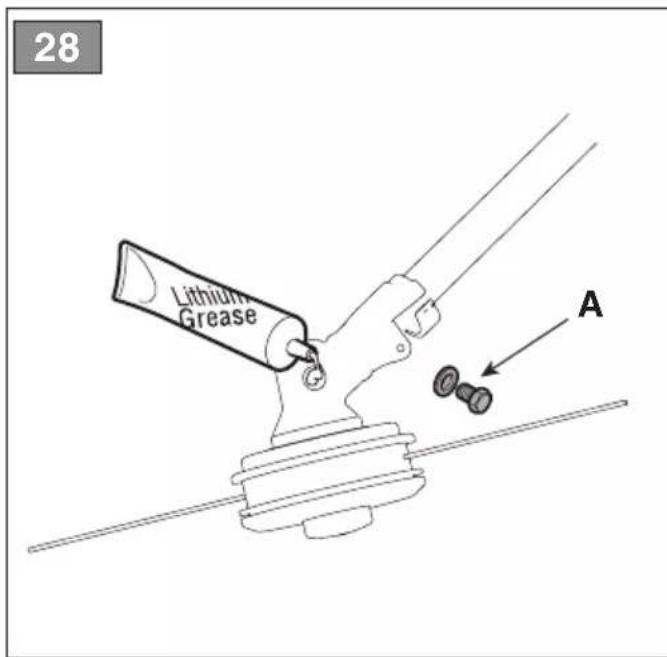
natural_image
Illustration of a hand using a power tool to apply material to a digital tablet (no text or symbols visible)
33
1
natural_image
Hand holding a mechanical component with arrows indicating direction (no text or symbols)1
2
natural_image
Technical line drawing of a mechanical assembly with no visible text or symbolsA =
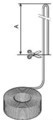
2 x 2,0 m (79 in.) - B 26/32 series
3
4
natural_image
Diagram of a fan or impeller with internal blades and directional arrows indicating motion (no text or symbols)5
6
B =
175 mm (6,9 in.) - B 42/52 series
natural_image
Cross-sectional diagram of a mechanical device with internal components and directional arrows indicating movement (no text or symbols)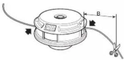


[3] 2-stroke air-cooled
[4] Displacement
[5] Power
[6] Engine rotation speed when idle
[7] Maximum engine rotation speed (cutting line head)
[8] Maximum engine rotation speed (blades)
[9] Maximum tool rotation speed (cutting line head)
[10] Maximum tool rotation speed (blades)
[11] Fuel tank capacity
[12] Fuel mixture (Petrol: 2-stroke oil)
[13] Spark plug
[14] Cutting width (cutting line head)
[15] Cutting width (3 point, 4 point and 8 point blade)
[16] Cutting width (saw blade)
[17] Connecting cutting line head
[18] Diameter of cutting line (max)
[19] Cutting means code
[20] Cutting means code (8 point blade)
[21] Cutting means code (saw blade)
[22] Protection code (wire holder head, 3 point, 4 point and 8 point blade)
[23] Protection code (saw blade)
[24]Weight
[25] Front, rear handle
[26]Handle bar
[27] Sound pressure level
[28] Uncertainty
[29] Measured sound power level
[30] Guaranteed sound power level
[31] Vibrations transmitted to hand on front handle
[32] Vibrations transmitted to hand on rear handle
[33] Vibrations transmitted to hand on right handle
[34] Vibrations transmitted to hand on left handle
[1] ES - DATOS TÉCNICOS
[2] Motor
[1] FI - TEKNISET TIEDOT
[2] Moottori
[1] LT - TECHNINIAI DUOMENYS
[2] Variklis
4.1 Assembly components....6
4.2 Grip assembly 6
4.3 Selecting the cutting means and specific guard 7
4.4 Fitting the guard on the cutting means..... 7
4.5 Fitting and removing the cutting means ..... 8
4.6 Assembly of transmission tube (models with separable rod)....9
4.7 Assembly of flexible transmission tube...... 9
- CONTROLS....9
5.1 Engine start / stop switch....9
5.2 Throttle control lever....9
5.3 Throttle safety lever 9
5.4 Manual starting grip....9
5.5 Choke control lever (if available)....9
5.6 Primer control button....9
5.7 Display (if available) 10
- USING THE MACHINE 10
6.1 Preliminary operations.... 10
6.2 Safety checks....10
6.3 Start-up 11
6.4 Operation 12
6.5 Operating suggestions 13
6.6 Stop....13
6.7 After use.... 13
- ROUTINE MAINTENANCE.... 13
7.1 General Information.... 13
7.2 Preparing the fuel blend 14
7.3 Refuelling 14
7.4 Cleaning the machine and the engine 14
7.5 Nuts and bolts 14
- OCCASIONAL MAINTENANCE 14
8.1 Angle transmission lubrication.... 14
8.2 Flexible shaft lubrication.... 14
8.3 Cleaning the air filter.... 15
8.4 Spark plug 15
8.5 Cutting means maintenance.... 15
8.6 Sharpening the wire cutting blade 16
8.7 Adjusting idle speed 16
8.8 Carburettor....16
-
STORAGE....16
-
HANDLING AND TRANSPORT 16
- ASSISTANCE AND REPAIRS 17
- WARRANTY COVERAGE.... 17
- MAINTENANCE TABLE.... 18
- TROUBLESHOOTING 19
1. GENERAL INFORMATION
1.1 HOW TO READ THIS MANUAL
Some of the paragraphs in this manual contain particularly important information in terms of safety and operation, and are highlighted differently, according to the following criteria:
NOTE or IMPORTANT These give details or further information on what has been previously indicated and aim to prevent damage to the machine or cause other damage.
The symbol represents a danger. Failure to observe the warning can lead to possible personal and/or third party injury and/or damage.
The paragraphs highlighted in a dotted grey square indicate optional characteristics not available on all models documented in this manual. Check if the characteristics are available on this model.
Whenever reference is made to a position on the machine "front", "back", "left" or "right" hand side, this refers to the operator's working position.
1.2 REFERENCES
1.2.1 Figures
The figures in these instructions for use are numbered 1, 2, 3, etc.
Components shown in the figures are marked A, B, C, etc.
Reference to component C in figure 2 is indicated with the wording: "See fig. 2.C" or simply "(Fig. 2.C)".
The figures are provided by way of example. The actual pieces can differ from those illustrated in this document.
1.2.2 Titles
The manual is arranged in chapters and paragraphs. The title of paragraph '2.1 Training" is a sub-title of "2. Safety regulations". References to titles or paragraphs are marked with the abbreviation chap. or par. and the relevant number. Example: "chap. 2" or "para. 2.1."
2. SAFETY REGULATIONS
2.1 TRAINING
⚠️ Become familiar with the controls and the proper use of the machine. Learn how to stop the machine quickly. Failure to follow the warnings and instructions may result in fire and/or serious injury.
- National legislation may restrict the use of the machine.
- Never allow the machine to be used by children or individuals who are not familiar with the instructions. Local laws may establish a minimum age for users.
- Never use the machine if the user is tired or unwell, or has taken medication, drugs, alcohol or substances that impair reflexes and concentration.
- Remember that the operator or user is responsible for accidents and unexpected events that can occur to other people or property. It is the user's responsibility to assess the potential risk of the area where work is to be carried out and to take all the necessary precautions to ensure his own safety and that of others, particularly on slopes or rough, slippery and unstable ground.
- If the machine is sold or lent to others, make sure that the operator looks over the user instructions contained in this manual.
2.2 PRELIMINARY OPERATIONS
Personal Protective Equipment (PPE)
- Always wear slim-fitting protective clothes with slash-proof protection, anti-vibration gloves, helmet, protective goggles, half-mask respirator, protective earplugs, cut resistant safety boots with non-slip soles.
- Never wear scarves, shirts, necklaces, bracelets, loose flowing clothing, laces or ties or any hanging or flapping accessory that could catch in the machine or in any objects or materials in the work area.
- Tie your hair back if it is long.
Work / Machine Area
- Thoroughly inspect the entire work area and remove anything that could be thrown by the machine or damage the cutting means/rotating units (stones, branches, iron wire, bones, etc.).
Internal combustion engine: fuel

DANGER! Petrol and blended fuels are highly flammable.
- Keep petrol and blended fuel in approved containers, in a safe place, away from any sources of heat or naked flames.
- Keep the containers out of the reach of children.
- Keep the containers free of residues of grass, leaves or excessive grease
- Do not smoke while blending the fuel, filling up/topping up with fuel or whenever handling the fuel.
- Use a funnel to top up with fuel only in the open air.
- Do not inhale fuel fumes.
- Never remove the tank cap or add fuel while the engine is running or when the engine is hot.
- Open the fuel tank slowly to allow the pressure inside to decrease gradually.
- Do not approach the tank opening with a naked flame to check its contents.
- If you have spilt some fuel, do not attempt to start the engine but move the machine away from the area of spillage and avoid creating any source of ignition until the fuel has evaporated and fuel vapours have dissipated.
- Replace caps of all fuel tanks and containers securely.
– Immediately clean up all traces of fuel spilt on the machine or on the ground. - Never start the machine in the same place in which you refilled it with fuel; the engine must be started in an area at least 3 metres from where you refuelled.
- Avoid getting any fuel or your clothing and, if this should happen, change your clothes before starting the engine.
2.3 DURING OPERATION
Work Area
- Do not operate the engine in confined spaces where dangerous carbon monoxide fumes can collect. The start-up operations must be carried out outdoors or in a well-ventilated area. Always remember that the exhaust gases are toxic.
- When starting up the machine, do not direct the silencer and therefore the exhaust fumes towards flammable materials.
- Do not use the machine in environments that pose the risk of explosion, in the presence of flammable liquids, gases or powders. Electrical contact or mechanical rubbing can generate sparks that can ignite powder or vapour.
- Work only in daylight or with good artificial light in good visibility conditions.
-
Keep people, children and animals away from the work area. Children must be supervised by another adult.
-
Make sure that no persons are within 15 metres of the machine's range of operation or within 30 metres for heavier cutting
- Where possible, avoid working on wet, slippery ground or on uneven or steep ground that does not guarantee stability for the operator.
- Pay careful attention to uneven ground (hills, dips), slopes, hidden hazards and obstacles that could limit visibility.
- Be very careful near ravines, ditches or embankments.
- Always work across the face of the slope and never up and down it, being very careful when changing direction, making sure the cutting means is always down-line
- Look out for traffic when using the machine near the road.
Conduct
- When working, the machine must always be held firmly in both hands, keeping the power unit on the right of the body and the cutting head below the line of the belt
- Always use caution and take on a firm and well-balanced position.
- Never run, always walk.
- Always keep the machine connected to the harness when working.
- Always keep hands and feet away from the cutting means, when starting and when using the machine.
- Attention: the cutting means will continue to rotate for a few seconds after disengagement or after you have switched off the engine
- Be careful of flying debris coming from the cutting means.
- Be careful of avoiding violent collisions between the cutting means and foreign objects/obstacles. Kickback may occur if the cutting means comes into contact with an obstacle/object. This contact can cause a rapid jerk in the opposite direction, pushing the cutting means up and towards the operator. Kickback can cause the operator to lose control of the machine, leading to serious consequences. To avoid kickbacks, take all the appropriate precautions indicated below:
– Firmly hold the machine, with two hands, and place your body and arms in a position that allows you to resist kickback.
- Do not extend the arms too high and do not cut above waist height.
- Only use the cutting means specified by the manufacturer.
– Follow the manufacturer's instructions concerning cutting means maintenance.
- Beware of injuries caused by devices used to cut the line length.
- Attention: The cutting element continues to rotate even after the engine has been switched off.
- Do not touch the parts of the engine that heat up during operation. Risk of burns.
- To avoid the risk of fire, do not leave the machine with the engine hot on leaves or dry grass or other flammable material.
- If something breaks or an accident occurs during work, turn off the engine immediately and move the machine away to prevent further damage; if an accident occurs with injuries or third parties are injured, carry out the first aid measures most suitable for the situation immediately and contact the medical authorities for any necessary health care. Carefully remove any debris which could cause damage or injury to persons or animals if ignored.
- The noise and vibration levels shown in these instructions are the maximum levels for use of the machine. The use of an unbalanced cutting element, the excessive speed of movement, or the absence of maintenance have a significant influence on noise emissions and vibrations. Consequently, it is necessary to take preventive steps to eliminate possible damage due to high levels of noise and stress from vibration; maintain the machine well, wear ear protection devices, and take breaks whilst working.
- Prolonged exposure to vibrations can cause injuries and neurovascular disorders (also called “Raynaud’s syndrome” or “white finger”), especially to people suffering from circulation disorders. The symptoms can regard the hands, wrists and fingers and are shown through loss of sensitivity, torpor, itching, pain and discolouring of or structural changes to the skin. These effects can be worsened by low ambient temperatures and/or by gripping the hand grips excessively tightly. If the symptoms occur, the length of time the machine is used must be reduced and a doctor consulted.
Restrictions of use
- Do not use the machine if you are unable to hold it with both hands or keep steady on your legs whilst working.
- Never use the machine with damaged, missing or incorrectly positioned guards.
- Do not change the engine adjustments, or exceed the maximum rpm. If the engine is forced to run at an excessive speed, the risk of personal injury increases.
- Do not strain the machine too much and do not use a small machine for heavy-duty work; if you use the right machine, you will reduce the risk of hazards and improve the quality of your work.
2.4 MAINTENANCE, STORAGE AND TRANSPORT
Ensure regular maintenance and correct storage to maintain machine safety and high performance levels.
⚠️ Never use the machine with worn or damaged parts. Faulty or worn-out parts must always be replaced and never repaired. Only use original parts: using parts that are not original or installed incorrectly affects machine safety, and can therefore cause accidents or personal injury and relieve the Manufacturer of all obligations and liability.
Maintenance
- To reduce the risk of fire, check for oil and/or fuel leaks on a regular basis.
- Be careful during adjustment of the machine to prevent entrapment of the fingers between moving parts of the cutting means and fixed parts of the machine.
Storage
- Do not store the machine with fuel in the tank in an area where fuel vapours could reach a naked flame, spark or strong source of heat.
- To reduce fire risks, do not leave containers with debris inside a room.
2.5 ENVIRONMENTAL PROTECTION
Protecting the environment must be a significant and top priority for machine use, to the benefit of civil co-habitation and of the environment that we live in.
- Avoid being an element of disturbance to the surrounding area. Use this machine at reasonable times of the day only (not early morning or late evening when the noise could cause disturbance).
- Adhere strictly to the local regulations governing the disposal of packaging, oil, fuel, filters, damaged parts or any other element which may have an impact on the environment; this waste must not be disposed of with regular waste, but must be separated and taken to collection centres, which will recycle the materials.
- Comply with local regulations for the disposal of waste materials.
- When the machine is withdrawn from service, do not dispose of it in the environment, but take it to a waste disposal facility in accordance with the local regulations in force.
3. ABOUT THE MACHINE
3.1 MACHINE DESCRIPTION AND INTENDED USE
This machine is gardening equipment and, specifically, a portable bush/edge trimmer with a thermal engine, designed for hobby use.
The machine essentially comprises of an engine which, through a drive shaft enclosed in a tube and an angle transmission unit, drives a cutting means configured in various ways to perform various functions.
The operator is able to sustain the machine with the aid of a harness and can operate the main controls, always keeping at a safe distance from the cutting means.
3.1.1 Intended use
This machine was designed and manufactured for:
- cutting grass and non-woody vegetation with a nylon line enclosed in a cutting line head;
- cutting tall grass, dry branches, twigs and woody shrubs of up to 2 cm diameter, with the aid of metal or plastic blades;
- cutting wooden parts and felling small trees (only with saw blade, if allowed);
- being used by one operator.
3.1.2 Improper use
Any other use that does not comply with the above, can be dangerous and cause damage to people and/or property. Examples of improper use may include, but are not limited to:
• using the machine for sweeping;
- trimming hedges or other jobs in which the cutting means is not used at ground level;
- pruning trees;
- using the machine with the cutting means above the operator's belt level;
- using the machine for cutting non-plant material;
- using cutting means other than those found in the "Technical Data" table. Risk of serious injury and injuries;
• using of the machine by more than one person.
IMPORTANT Improper use of the machine will void the warranty and relieves the Manufacturer of any liability, placing all responsibility for damage or injury, to him/herself or third parties, on the user.
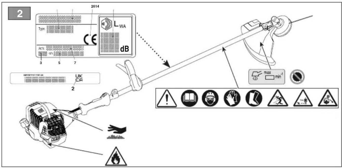
3.2 SAFETY SIGNS
The machine has various symbols on it (fig. 2). Their function is to remind the operator of the correct conduct for use, with due care and caution.
Meanings of the symbols:

WARNING! DANGER! The failure to use this machine correctly can be hazardous for oneself and others.

WARNING! Read the owner's manual before using the machine.

Anyone operating the machine under normal conditions for continuous daily use may be exposed to a noise level equal to or exceeding 85 dB (A). Use ear protection devices, goggles and helmet.

Wear protective gloves and safety footwear!


PROJECTION HAZARD! People or pets must be kept at least 15 m away when using the machine!

Maximum speed of the cutting means.


Do not use circular saw blades. Danger: Using circular saw blades on models that are not designed for them exposes the user to the risk of very serious or even fatal injuries.

WARNING! Petrol is flammable. Allow the engine to cool at least 2 minutes before refuelling.

Beware of blade kickback.

WARNING! - Keep away from hot surfaces.
IMPORTANT Any damaged or illegible decals must be replaced. Order replacement decals from an Authorised Service Centre.
3.3 PRODUCT IDENTIFICATION LABEL
The product identification label provides the following data (Fig. 1):
- Sound power level
- Conformity marking
- Month / Year of manufacture
- Type of machine
- Serial number
- Name and address of Manufacturer
- Article code
Write the identification data of the machine in the specific space on the label on the back of the cover page.
IMPORTANT Quote the information on the product identification label whenever you contact an Authorised Service Centre.
3.4 MAIN COMPONENTS
The machine is composed of a series of main components that have the following functions (Fig.1):
A. Engine: drives the cutting means via drive tube and angle transmission.
B. Transmission tube: The tube houses the drive shaft which transmits rotary motion to the angle transmission.
1. Rigid transmission tube
2. Flexible transmission tube
C. Angle transmission: final part of the transmission tube that transmits motion to the cutting means.
D. Cutting means: the element designed to cut vegetation
-
Cutting line head: nylon line cutting means.
-
3 point, 4 point and 8 point blades: metal disk cutting means.
-
Saw blade (if allowed): circular metal disk cutting means with peripheral cutting teeth.
E. Cutting means guard: it is a safety device which prevents objects drawn up by the cutting means from being hurled away from the machine.
-
Cutting line head
-
Saw blade (if allowed)
F. Front hand grip: semi-circular shaped, it is used to handle the machine and is equipped with a leg guard.
G. Rear hand grip: used to handle the machine and equipped with the main on/off/acceleration control buttons.
H. Leg guard: a safety guard that prevents accidental contact with the cutting means during use.
I. Handle bar: "ox horn" shaped handle bar transversely placed to the rod and asymmetrically to it; used to control the machine and equipped, on the right hand side, with the main on/off/acceleration control buttons.
J. Display: information regarding the machine operation and maintenance is displayed.
K. Connection point (of the harness): where the harness is connected to the machine.
L. Harness: device made up of a fabric belt which, placed over the shoulders, helps to support the weight of the machine during work.
-
single strap
-
double strap
-
with backpack
M. Blade protection (for machine transport and handling): protects against accidental contact with the cutting means that can cause serious injuries.
4. ASSEMBLY
IMPORTANT The safety regulations to follow are described in chap. 2. Strictly comply with these instructions to avoid serious risks or hazards.
For storage and transport purposes, some components of the machine are not installed in the factory and have to be assembled after unpacking. Follow the instructions below.
⚠️ Unpacking and completing the assembly should be done on a flat and stable surface, with enough space for machine handling and its packaging, always making use of suitable equipment. Do not use the machine until all the indications provided in the “ASSEMBLY” section have been carried out.
4.1 ASSEMBLY COMPONENTS
The packaging includes assembly components.
4.1.1 Unpacking
- Carefully open the packaging, paying attention not to lose components
- Consult the documentation in the box, including these instructions.
- Remove all the unassembled parts from the box.
- Slide the trimmer-cutter out of the box.
- Dispose of the box and packaging in compliance with local regulations.
4.2 GRIP ASSEMBLY
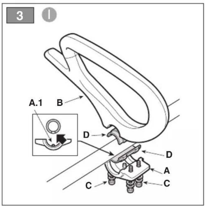
4.2.1 Fitting the front hand grip - Type I
-
Position the cap (Fig. 3.A) by inserting the pin (Fig. 3.A.1) into one of the holes available on the transmission tube.
-
Fit the front grip complete with leg guard barrier (Fig. 3.B) using the screws (Fig. 3.C), taking care to keep the two anti-vibration half-shells in place (Fig.3.D).
-
Fully tighten the screws (Fig. 3.C).
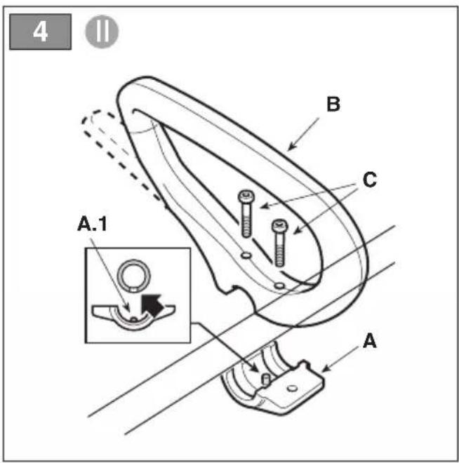
4.2.2 Fitting the front hand grip - Type II
-
Position the cap (Fig. 4.A) by inserting the pin (Fig. 4.A.1) into one of the holes available on the transmission tube.
-
Fit the front hand grip (Fig. 4.B) with the screws (Fig. 4.C).
-
Fully tighten the screws (Fig. 4.C).
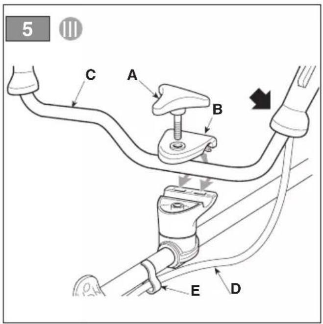
4.2.3 Fitting the handle bar - Type III
- Unscrew the central knob (Fig. 5.A) and remove the cap (Fig. 5.B).
- Insert the handle bar (Fig. 5.C), making sure that the controls are on the right.
- Arrange the handle bar in the most comfortable working position and lock it using the cap (Fig. 5.B) and the knob (Fig. 5.A).
- Hook up the control sheath (Fig. 5.D) to the appropriate cable clamp (Fig. 5.E).
NOTE Loosen the knob (Fig. 5.A) in order to rotate the handle bar and reduce its overall dimensions for storage purposes.
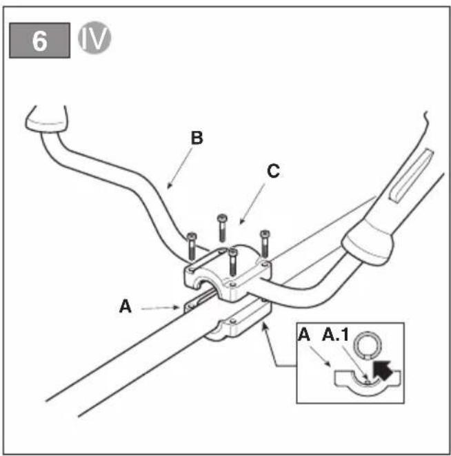
4.2.4 Fitting the handle bar - Type IV
- Position the cap (Fig. 6.A) by inserting the pin (Fig. 6.A.1) into one of the holes available on the transmission tube.
- Insert the handle bar (Fig. 6.B), making sure that the controls are on the right.
- Arrange the handle bar in the most comfortable working position and lock it using the screws (Fig. 6.C).
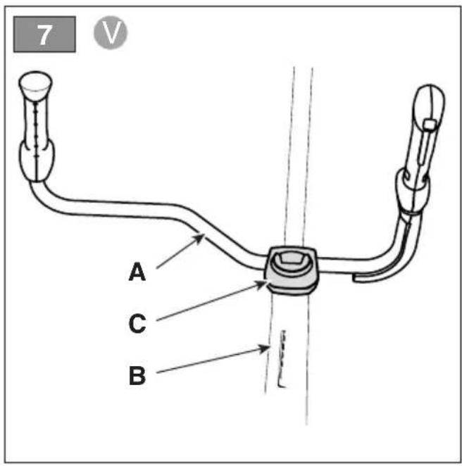
4.2.5 Fitting the handle bar - Type V
- Insert the handle (Fig. 7.A) into its seat in the transmission tube (Fig. 7.B), making sure that the controls are on the right.
- Tighten and lock the knob (Fig. 7 C) on the handle bar (Fig. 7 A).
4.3 SELECTING THE CUTTING MEANS AND SPECIFIC GUARD
⚠️ Every cutting means must be fitted with a specific guard, as indicated by the following directions in the Technical Data table.
Choose the most suitable cutting means for the job to be done, according to these general instructions:
- the cutting line head can eliminate tall grass and non-woody vegetation near fences, walls, foundations, pavements, around trees, etc. or to completely clean a particular area of the garden;
- the 3-point, 4-point and 8-point blades are suitable for cutting brushwood and small shrubs up to 2cm in diameter;
- the saw blade (if allowed) is used to cut wooden parts and fell small trees;
IMPORTANT Whenever you have to change the cutting means, disassemble all its elements.
4.4 FITTING THE GUARD ON THE CUTTING MEANS
⚠ Wear protective gloves.
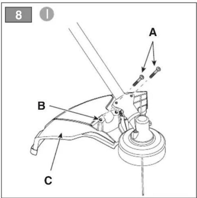
4.4.1 Fitting the cutting means guard (wire holder head, 3-point, 4-point and 8-point blade) - Type I
- Unscrew the screws (Fig. 8.A).
- Position the guard (Fig. 8.C) in line with the holes on the transmission (Fig. 8.B).
- Secure the guard (Fig. 8.A) fully tightening the screws (Fig. 8.C).
NOTE The cutting means guard (Fig. 8.E) has the following symbol:
It indicates the rotation direction of the cutting means.
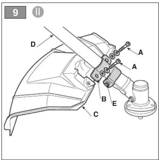
4.4.2 Fitting the cutting means guard (wire holder head, 3-point, 4-point and 8-point blade) - Type II
IMPORTANT Each time you use this guard, make sure that the transmission pipe plate (Fig. 9.B, Fig. 9.E) is fitted.
- Unscrew the screws (Fig. 9.A).
- Position the guard (Fig. 9.C) in line with the holes on the transmission (Fig. 9.B).
- Secure the guard (Fig. 9.A) fully tightening the screws (Fig. 9.C).
NOTE The cutting means guard (Fig. 9.E) has the following symbol:

It indicates the rotation direction of the cutting means.
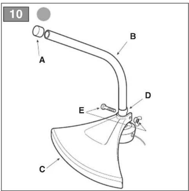
4.4.3 Fitting the cutting means guard (wire holder head) - Type III
- Remove the protection cap (Fig. 10.A) from the end of the lower part of the rod (Fig. 10.B).
- Fasten the protection (Fig. 10.C) to the support (Fig. 10.D) using the supplied screws (Fig. 10.E).
NOTE The cutting means guard (Fig. 10.C) has the following symbol:
It indicates the rotation direction of the cutting means.
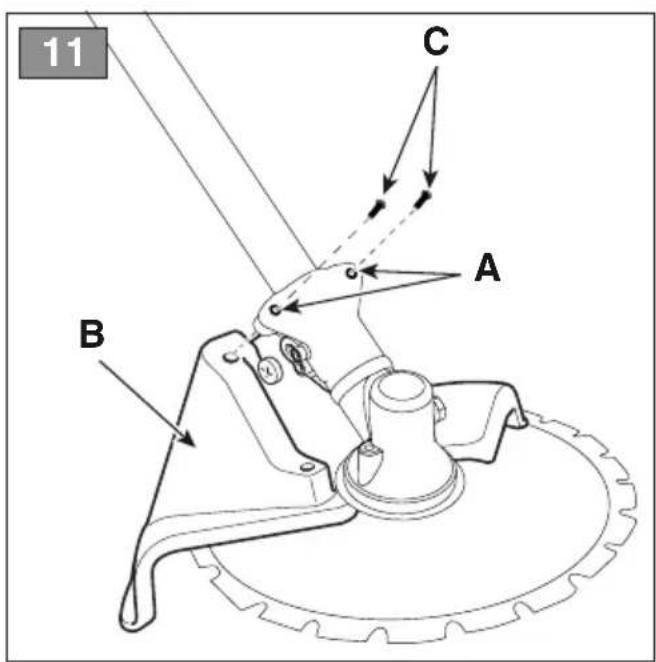
4.4.4 Mounting the cutting means guard (saw blade, if allowed)
⚠ T his protective guard should not be used for other cutting means.
- Remove any protective guards used for other cutting means.
- Place the guard (Fig. 11.B) in line with the holes on the transmission (Fig. 11.A).
- Secure the guard (Fig. 11.A) by fully tightening the screws (Fig. 11.C).
4.5 FITTING AND REMOVING THE CUTTING MEANS

Wear protective gloves.
4.5.1 Fitting the cutting line head - Type I
- Fit the inner lock ring (Fig.12.A) on the shaft in the indicated direction, making sure that the grooves are perfectly coupled with those on the angle transmission (Fig. 12.B).
- Insert the wrench supplied (Fig. 12.C) into the appropriate hole on the angle transmission (Fig. 12.D) and rotate the lock ring by hand by pushing the wrench (Fig. 12.C) until it engages and blocks rotation.
- Fit the cutting wire head (Fig. 12.F) by screwing it anticlockwise.
- Remove the wrench (Fig. 12.C) to reset rotation.
IMPORTANT When using the wire head, the guard (Fig. 12.E) must always be fitted with a wire cutter blade (Fig. 32.A).
4.5.2 Disassembling the cutting line head - Type I
- Insert the wrench supplied (Fig. 12.C) into the appropriate hole on the angle transmission (Fig. 12.D) and rotate the lock ring by hand by pushing the wrench (Fig. 12.C) until it engages and blocks rotation.
- Remove the wire holder head (Fig. 12.F) by unscrewing clockwise.
4.5.3 Fitting the cutting line head - Type II
- With a suitable wrench, block the rotation of the shaft (Fig. 12.G).
- Fit the cutting line head (Fig. 12.H) screwing it clockwise.
4.5.4 Disassembling the cutting line head - Type II
- With a suitable wrench, block the rotation of the shaft (Fig. 12.G).
- Remove the wire holder head (Fig. 12.H) by unscrewing it anticlockwise.
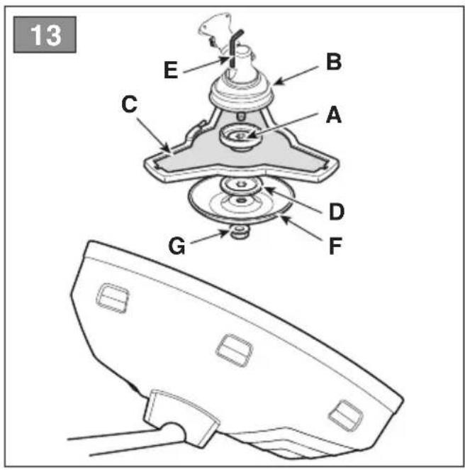
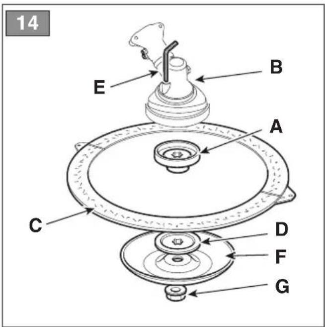
4.5.5 Fitting the 3-point, 4-point and 8-point blade and saw blade (if allowed)

Apply the guard to the blade.
- Mount the inner locking ring (Fig. 13.A, Fig. 14.A) on the shaft in the indicated direction, making sure that the grooves are perfectly coupled with those on the angle transmission (Fig. 13.B, Fig. 14.B).
- Fit the blade (Fig. 13.C, Fig. 14.C) and the outer locking ring (Fig. 13.D, Fig. 14.D) with the flat part facing the blade.
- Insert the wrench supplied (Fig. 13.E, Fig. 14.E) into the special hole on the transmission, rotate the blade by hand (Fig. 13.C, Fig. 14.C) and push the wrench (Fig. 13.E, Fig. 14.E) until it engages in the angle transmission hole (Fig. 13.B, Fig. 14.B) and locks rotation.
- Fit the sump (Fig. 13.F, Fig. 14.F) and tighten the nut (Fig. 13.G, Fig. 14.G) fully anticlockwise (25 Nm).
- Remove the wrench (Fig. 13.E, Fig. 14.E) to reset rotation.
4.5.6 Removing the 3-point, 4-point and 8-point blade and saw blade (if allowed)

Apply the guard to the blade.
- Insert the wrench supplied (Fig. 13.E, Fig. 14.E) into the special hole, rotate the blade by hand (Fig. 13.C, Fig. 14.C) and push the wrench (Fig. 13.E, Fig. 14.E) until it engages in the angle transmission hole (Fig. 13.B, Fig. 14.B) and locks rotation.
- Unscrew the nut (Fig. 13.G, Fig. 14.G) clockwise and remove the sump (Fig. 13.F, Fig. 14.F).
- Remove the outer locking ring (Fig. 13.D, Fig. 14.D); then remove the blade (Fig. 13.C, Fig. 14.C) and the inner locking ring (Fig. 13.A, Fig. 14.A).
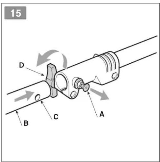
4.6 ASSEMBLY OF TRANSMISSION TUBE (MODELS WITH SEPARABLE ROD)
- Remove the stop pin (Fig. 15.A) and push the lower part of the rod (Fig. 15.B) until you hear the click of the stop pin (Fig. 15.A) in the hole (Fig. 15.C) of the rod. Insertion can be facilitated by slightly rotating the lower part (Fig. 15.B) in both directions; complete insertion is noticeable by the pin (Fig. 15.A) which must be fully retracted.
- When insertion is complete, fully tighten the knob (Fig.15.D).
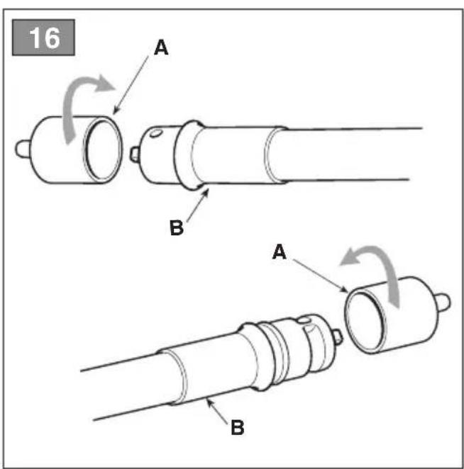
4.7 ASSEMBLY OF FLEXIBLE TRANSMISSION TUBE
- Remove the protective caps (Fig. 16.A) from the two ends of the flexible transmission tube (Fig. 16.B), paying attention that they are different from each other.
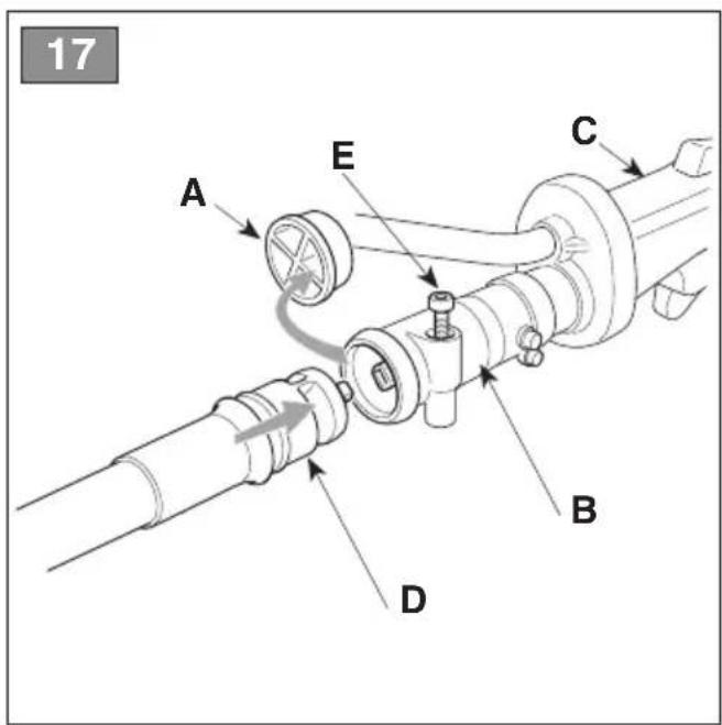
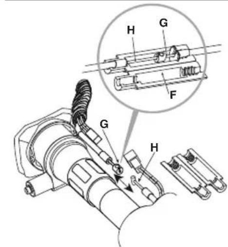
- Remove the protective cap (Fig.17.A) from the protruding tube (Fig.17.B) from the rear hand grip (Fig.17.C)
- Insert the end with the groove (Fig.17.D) into the protruding tube (Fig.17.B) from the rear hand grip (Fig.17.C) and fix it with the screw (Fig.17.E), making sure it remains locked.
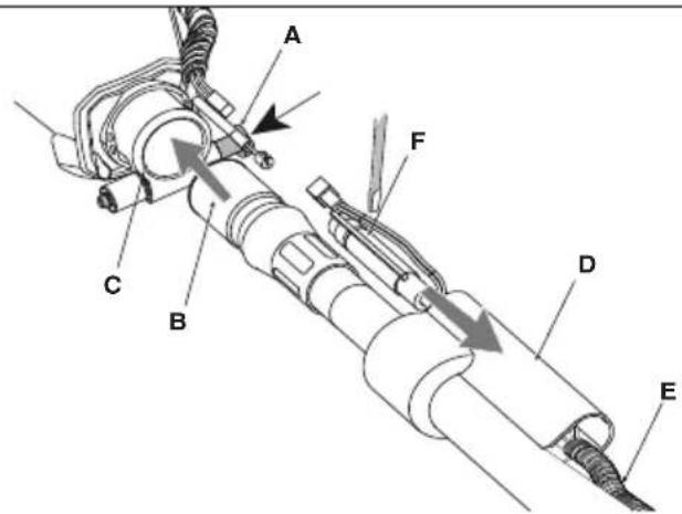
- Press the pin (Fig.18.A) and insert the hose (Fig.18.B) in the seat of the power unit (Fig.18.C).
- Release the pin (Fig.18.A) to lock the end of the tube (Fig.18.B).
- Remove the rubber protection (Fig.18.D) and pass the cables inside it (Fig.18.E).
- Open the throttle cable protection device (Fig.18.F) using a screwdriver.
- Connect the cables (Fig.18.G) and (Fig.18.H).
- Close the protection device again (Fig.18.F).
- Connect the connectors (Fig.18.I) and (Fig.18.L).
- Reposition the rubber protection (Fig.18.D).
5. CONTROLS
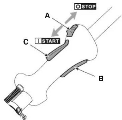
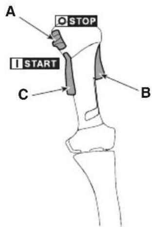
5.1 ENGINE START / STOP SWITCH
Used to start and stop the engine. The switch has two positions (Fig. 19.A):

STOP - the engine stops and cannot be started.

START - the engine can be started and operated.
5.2 THROTTLE CONTROL LEVER
Used to adjust the speed of the cutting means.
The throttle safety lever (Fig. 19.B) can only be operated if the throttle safety lever is pressed at the same time (Fig. 19.C).
The correct working speed is set using throttle safety lever (Fig. 19.B) to the end of its stroke.
5.3 THROTTLE SAFETY LEVER
The throttle safety lever (Fig. 19.C) allows the throttle control lever to be used (Fig. 19.B).
5.4 MANUAL STARTING GRIP
Allows the engine to be started by hand (Fig. 19.1).
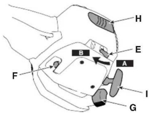
5.5 CHOKE CONTROL LEVER (IF AVAILABLE)
It is used to cold start the engine. The control features two positions (Fig. 19.E):

Position A - The choke is disengaged (normal operation and hot engine start).
Position B - The choke is engaged (for engine cold start).
5.6 PRIMER CONTROL BUTTON

Press the primer's rubber button to inject fuel into the carburettor, thereby making it easier to start the engine (Fig. 19.F).
5.7 DISPLAY (IF AVAILABLE)
The display (Fig. 19.J) shows information regarding the machine operation and maintenance.

Tachometer.
The digits on the display show the number of engine rpm.

Timer.
The digits on the display show the machine's hours (H) and minutes (M) of operation.
MAINTENANCE
Maintenance.
Icon indicates that no maintenance is required.
Icon starts to flash when the maintenance hourly threshold is reached. The frequency and types of maintenance are summarised in the "Maintenance Table" (see chapter 13). The flashing continues for 1 hour.
6. USING THE MACHINE
IMPORTANT The safety regulations to follow are described in chap. 2. Strictly comply with these instructions to avoid serious risks or hazards.
IMPORTANT The machine is supplied without fuel.
6.1 PRELIMINARY OPERATIONS
Before using the machine:
- place the machine in a stable horizontal position on the ground;
- choose the most suitable cutting means for the job to be done (par. 4.3);
- fill up with fuel. For information about how to prepare the fuel blend, methods and precautions for refuelling, see sections 7.2 and 7.3;
- wear the harness correctly (see section 6.1.1).
6.1.1 Using the harness
The straps must be adjusted in accordance with the height and build of the operator.
- Single strap models
The harness must be worn before securing the machine to the attachment.
The strap (Fig. 20.A) must pass over the left shoulder, towards the right side.
The strap must be worn with:
– the support (Fig. 20.A.1), the machine's snap hook (Fig.20.A.2), and the quick release hook (Fig. 20.A.3) on the right side.
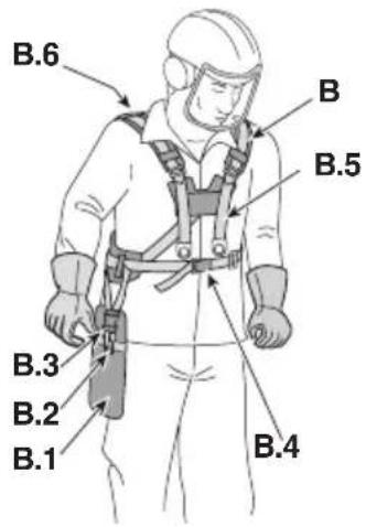
- Double strap models
The harness must be worn before securing the machine to the attachment.
The strap (Fig. 20.B) must be worn with:
- the support (Fig. 20.B.1), the machine's carbine hook (Fig. 20.B.2) and the quick release (Fig. 20.B.3) located on the right side;
– the quick release at the front (Fig. 20.B.4);
– the strap crossover on the back of the operator (Fig. 20.B.6);
– the buckles correctly fastened (Fig. 20.B.5).
The straps must be tightened so that they distribute the load evenly over the shoulders.
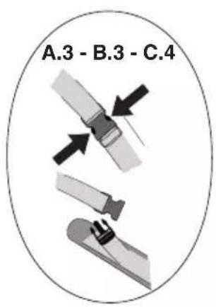
IMPORTANT In case of danger, unhook the machine using the quick release (Fig. 20.B.3).
• Models with backpack
The backpack must be put on after turning on the machine.
The backpack (Fig. 20.C) must be worn with:
– the shoulder straps on the operator's shoulders (Fig. 20.C.1);
– the buckles correctly fastened (Fig. 20.C.2).
- the machine's carbine hook located on the right side (Fig. 20.C.3);
– the quick release at the front (Fig. 20.C.4);
The straps must be tightened so that they distribute the load evenly over the shoulders.
IMPORTANT In case of danger, unhook the harness using the quick release (Fig. 20.C.4).
6.2 SAFETY CHECKS
Run the following safety checks and ensure that the results correspond to those outlined in the tables.

Always carry out the safety checks before
6.2.1 General check
| Object Result | |
| Grips (Fig. 1.F, Fig. 1.G, Fig. 1.I) | Clean, dry and fixed firmly to the machine. |
| Cutting means guard. (Fig. 1.E.1, Fig. 1.E.2) | Suitable for the cutting means used, correctly and securely attached to the machine, not worn/ deteriorated or damaged. |
| Harness connection point (Fig. 1.K) | Correctly positioned |
| Quick release (Fig. 20.A.3, Fig. 20.B.3, Fig. 20.C.4) | Efficient. It must allow the machine to be released quickly in case of danger. |
| Screws on the machine and the cutting means | Correctly tightened (not loose) |
| Cutting means (Fig. 1.D.1, Fig.1.D.2, Fig. 1.D.3 ) | Not damaged or worn. |
| Metal blade (if fitted) (Fig.1.D.2, Fig. 1.D.3) | Well sharpened |
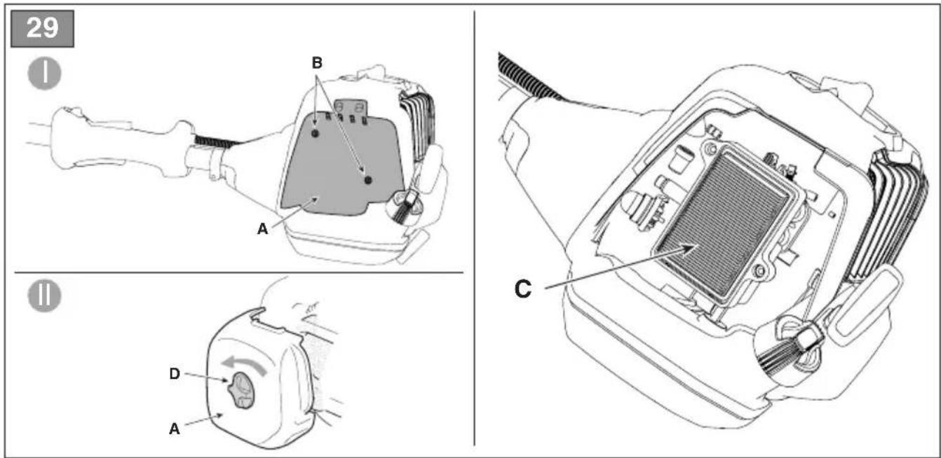
| Air filter (Fig. 29.C) Clean | |
| Electrical cables and spark plug cable | In good condition to avoid causing sparks. |
| Spark plug cap (Fig. 19.H) | In good condition and correctly fitted on the spark plug |
6.2.2 Machine operating test
| Action Result | |
| Start the machine (section 6.3); | The cutting means (Fig. 1.D.1, Fig. 1.D.2, Fig. 1.D.3) must not move when the engine is idling. |
| Simultaneously activate the throttle control lever (Fig. 19.B) and throttle safety lever (Fig. 19.C). | They must be able to move freely without forcing. |
| Release the throttle control lever (Fig. 19.B) and the throttle safety lever (Fig. 19.C) | The levers must return automatically and quickly to the neutral position and the engine must return to idle speed. |
| Press the accelerator control lever (Fig. 19.B) | The throttle lever remains locked (Fig. 19.B). |
| Operate the engine start/stop switch (Fig. 19.A) | The switch must move easily from one position to another. |
If any of the results fail to match the indications provided in the tables below, it is not possible to use the machine! Take it to a service centre to be checked and repaired if necessary.
6.3 START-UP
Before starting the engine:
- arrange the machine in a stable position on the ground;
- remove the cutting means guard (Fig. 1.M) (if used);
- make sure that the blade (Fig. 1.D.2, Fig. 1.D.3) (if used) does not touch the ground or other objects.
6.3.1 Cold start
⚠ "Cold" start means starting performed at least 5 minutes after stopping the engine or after refuelling.
IMPORTANT To prevent deformation, the transmission tube must not be used as a support for hands or knees during start-up.
IMPORTANT To avoid breakage, do not pull the rope along its entire length, do not slide it along the edge of the guide hole and release the knob gradually to prevent it rewinding in an uncontrolled way
- Make sure that the switch (Fig.19.A) is in position "I".
- only for models with choke: Engage the choke, moving the lever to "B" position (Fig. 19.E).
- Press the primer control button (Fig. 19.F) 10 times to facilitate carburettor ignition. Make sure the hole is covered by your finger when you press the command.
- Hold the machine firmly on the ground, with one hand on the drive unit, to avoid losing control of it when starting (Fig. 21).
- Slowly pull the starter knob by 10-15 cm, until you feel a certain resistance, and then pull again a few times until you hear the first combustions.
- only for models with choke: Disengage the choke, moving the lever to "A" position (Fig. 19.E).
- Pull the starter knob again until the engine is properly switched on.
- Operate the throttle lever briefly (Fig. 19.B) and set the engine to idle.
- Allow the engine to idle for at least 1 minute before using the machine.
IMPORTANT If the starter rope knob is operated repeatedly, the engine may choke and start up may become difficult.
If the engine floods in this way, see section 14.
6.3.2 Hot start
For hot start (immediately after stopping the engine), follow steps 1 - 2 - 3 - 4 - 6 - 7 of the previous procedure.
6.4 OPERATION
NOTE Before starting any tasks for the first time, get to know the machine, learn the most suitable cutting techniques, make sure your are wearing the harness correctly, grip the machine firmly and make the movements required by the job.
To use the machine proceed as follows:
- always keep the machine connected to the correctly worn harness (see par. 6.1.1)
- when working, the machine must always be firmly held in both hands, keeping the power unit on the right of the body and the cutting unit below the line of the belt.
6.4.1 Work techniques
6.4.1.a Cutting line head
⚠️ Use ONLY nylon lines. The use of metal lines, plastic coated metal lines and/or lines that are not suitable for the head can cause serious injuries and wounds.
Do not use the machine for sweeping, tilting the cutting line head. The engine is powerful enough to throw objects and small stones 15 metres or more, causing damage to objects and injury to people;
a. Cutting motion (Scything)
Proceed at a regular pace, with a circular motion similar to a traditional scythe, without tilting the cutting line head during the operation (Fig. 22).
First try cutting at the right height in a small area, so as to then achieve a uniform cutting height keeping the cutting line head at a constant
distance from the ground.
For heavier cutting it can be useful to tilt the cutting line head to the left by about 30^ .
Do not work in this way if there is the possibility of causing objects to be thrown, which could harm people, animals or cause damage.
b. Precision cutting (Trimming)
Keep the machine slightly tilted so that the lower part of the cutting line head does not touch the ground and the cutting line is at the required point, always keeping the cutting means at a distance from the operator.
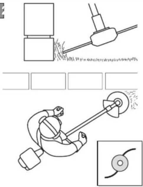
c. Cutting near fences/foundations
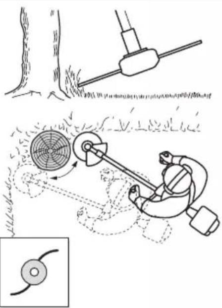
Move the cutting line head slowly towards fences, posts, rocks, walls, etc. without hitting them hard (Fig. 23).
If the line strikes a solid object it could break or become worn; if it gets tangled in a fence it could break suddenly.
In any case, cutting around pavements, foundations, walls, etc. can cause greater wear than normal to the line.
d. Cutting around trees
Walk round the tree from left to right, approaching the trunk slowly so as not to strike the tree with the line and keeping the cutting line head tilted forward slightly (Fig. 24).
Remember that the nylon line could lop off or damage small shrubs and that the impact of the nylon line against the trunk of bushes or trees with soft bark could seriously damage the plant.
6.4.1.b 3 point, 4 point and 8 point blades
Start cutting from above the vegetation and then descend with the mowing blade to cut branches by chopping them into small pieces (Fig. 25).
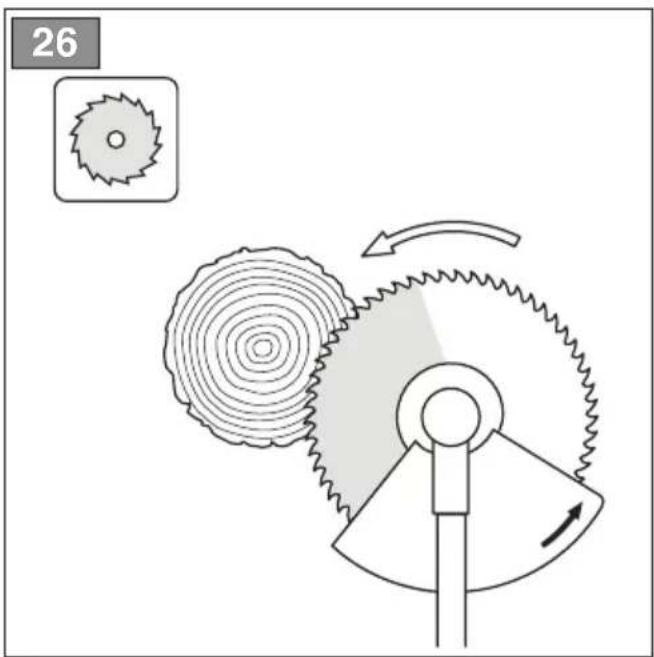
6.4.1.c Saw blade (if allowed)
⚠️ Where permitted, the saw blade must be used with the specific guard always fitted (section 4.4.2). The blade should always be well sharpened to reduce the risk of kickbacks.
When felling small trees, assess the direction of fall of the tree when cut, taking wind direction also into consideration.
To obtain good results when felling small trees, make the cut with rapid movements towards the branch or trunk to be cut with the engine at maximum rpm.
Avoid using the right side of the blade since their is a high risk of kickback or jamming the blade in view of the direction of rotation (Fig. 26).
6.4.2 Adjusting the length of the cutting line head during work
This machine is fitted with a semi-automatic wire release head.
Head line length should be adjusted:
- when the line is consumed and becomes shorter;
– when engine rotation seems higher than normal;
– when cutting efficiency seems reduced.
To release new line:
- tap the cutting line head against the ground (Fig. 27) with the throttle control lever pressed fully down;
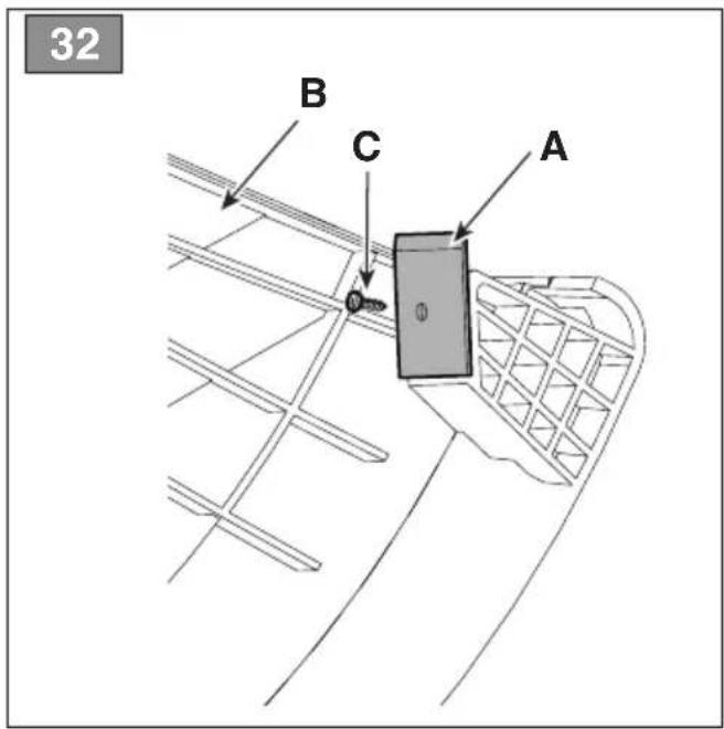
- the wire is automatically released and the wire cutting knife (Fig. 32.A) cuts the excess length.
6.5 OPERATING SUGGESTIONS
During use, it is advisable to remove cut vegetation wrapped around the machine at regular intervals to avoid the engine overheating (Fig. 1.A) caused by grass trapped under the cutting means guard (Fig. 1.E.1, Fig 1.E.2).
Proceed as follows:
- stop the machine (par. 6.6);
– disconnect the cap off the spark plug (Fig. 19.H)
- wear protective gloves;
– remove the caught-up grass with a screwdriver to allow the engine to be properly cooled.
NOTE During the first 6-8 hours of machine operation, avoid using it at maximum speed.
6.6 STOP
To stop the machine:
- Release the throttle lever briefly (Fig. 19.B) and allow the engine to idle for a few seconds
- turn the switch (Fig.19.A) to position "O";
- Wait until the cutting means stops.

When you set the throttle to idle, it will a few seconds for the cutting means to
IMPORTANT Always stop the machine when moving between work areas.

The engine may be very warm ediately after it is shut off. Do not touch. can cause burn injuries.
6.7 AFTER USE
- Detach the spark plug cap.
- When the cutting means has halted, fit the blade guard;.
- Allow the engine to cool before storing in an enclosed space.
- Clean (par. 7.4).
- Make sure there are no loose or damaged components. If necessary, replace damaged components and tighten any slack screws and bolts.
IMPORTANT Stop the machine (section .6.6), remove the spark plug cap (Fig. 19.H) and fit the blade guard whenever the machine is left unattended.
7. ROUTINE MAINTENANCE
7.1 GENERAL INFORMATION
IMPORTANT The safety regulations to follow are described in chap. 2. Strictly comply with these instructions to avoid serious risks or hazards.

Before performing any maintenance ations:
- stop the machine;
- remove the spark plug cap (Fig. 19.H);
- when the cutting means is stationary, apply the blade protection cover, (except when working directly on the blade);
- allow the engine to cool before storing in an enclosed space;
- use suitable clothing, protective gloves and goggles;
-
read the relevant instructions;
-
The frequency and types of maintenance are summarised in the "Maintenance Table" (see chapter 13). The table will help you maintain your machine's safety and performance. It summarises the main interventions to be made and the frequency applicable to each of them. Carry out the relevant task as soon as it is scheduled to be performed.
- The use of non-original parts and accessories could have negative effects on machine operation and safety. The manufacturer declines any responsibility for damage or injury caused by said products.
• Genuine spare parts are supplied by Authorised Assistance Centres and Dealers.
IMPORTANT Any maintenance and adjustment operations not described in this manual must be carried out by your dealer or Authorised Service Centre.
7.2 PREPARING THE FUEL BLEND
This machine is equipped with a 2-stroke engine that requires a blend of petrol and lubricating oil.
IMPORTANT Using petrol alone damages the engine and will void the warranty.
IMPORTANT Use only high quality fuels and lubricants to maintain performance and ensure the durability of mechanical parts.
7.2.1 Petrol - characteristics
Use only unleaded petrol (green petrol) with an octane of no less than 90 N.O.
IMPORTANT Green petrol tends to create deposits in the container if stored for more than 2 months. Always use fresh petrol!
7.2.2 Oil - characteristics
Use only high quality synthetic oil specific for 2-stroke engines.
Your Dealer will have oils specially designed for this type of engine which can guarantee a high level of protection.
IMPORTANT To know the percentages of oil and petrol to be used, see the "TECHNICAL DATA" table.
7.2.3 Preparing and storing the fuel blend
Preparing the fuel blend:
- add approximately half of the amount of petrol to a type-approved canister;
- add all the oil;
- add the rest of the petrol;
- close the cap and shake vigorously.
IMPORTANT The fuel blend is subject to ageing. Do not prepare excessive quantities of fuel blend to prevent the formation of deposits.
IMPORTANT Keep containers of fuel blend and petrol separate and clearly identified to avoid swapping them at the time of use.
IMPORTANT Clean the petrol and fuel blend containers at regular intervals to remove any deposits.
7.3 REFUELLING
Before refuelling:
- vigorously shake the canister containing the fuel blend;
- place the machine on a level surface in a stable position with the fuel tank cap facing upwards (Fig. 19.G).
NOTE The fuel tank (Fig. 19.G) has the following symbol:

Fuel blend tank.
- Clean the fuel cap and the surrounding area to avoid ingress of dirt when refuelling.
- Carefully open the fuel tank slowly to allow the pressure to decrease gradually.
- Refuel using a funnel; do not fill the tank right to the top.
7.4 CLEANING THE MACHINE AND THE ENGINE
Always clean the machine after use.
To reduce the risk of fire:
- keep the machine and especially the engine free from residues of grass, leaves or excessive grease; - frequently clean the cylinder fins with compressed air and eliminate sawdust, twigs, leaves or other debris from the silencer area.
To avoid overheating and damage to the engine, always keep the cooling air vents clean and free of sawdust or debris.
7.5 NUTS AND BOLTS
- Keep all nuts, bolts and screws tight to be sure the equipment is in safe working condition.
- Check regularly that the handles are fixed firmly.
8. OCCASIONAL MAINTENANCE
8.1 ANGLE TRANSMISSION LUBRICATION
Lubricate with lithium based grease.
Remove the screw (Fig. 28.A) and insert the grease by rotating the shaft by hand until the grease comes out; then refit the screw (Fig. 28.A).
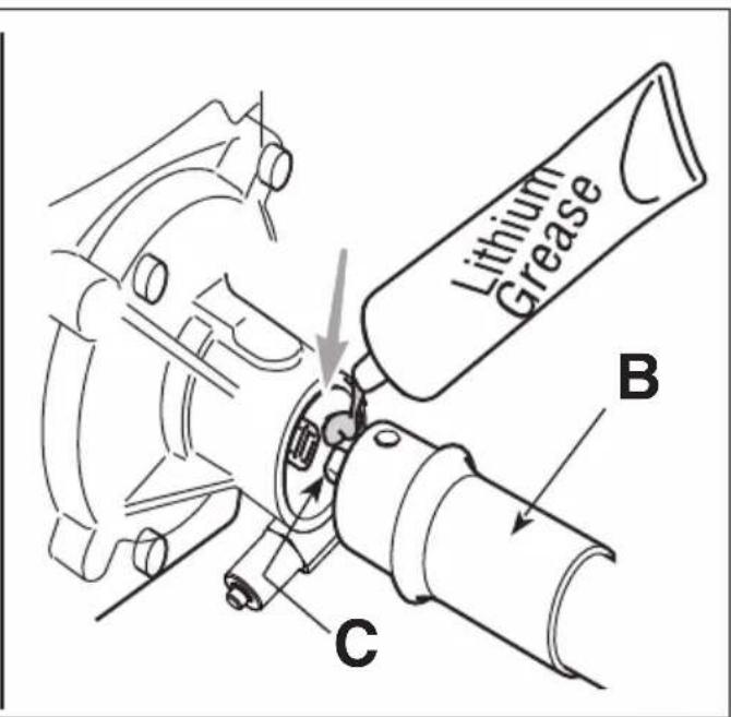
8.2 FLEXIBLE SHAFT LUBRICATION
Lubricate with lithium based grease.
- Unhook the tube (Fig. 28.B) from the motor side;
- remove the flexible shaft (Fig. 28.C);
- apply the grease by manually rotating the shaft until the grease is distributed over the entire surface; then reassemble everything (par.4.6)
8.3 CLEANING THE AIR FILTER
IMPORTANT Cleaning the air filter is essential for correct operation and durability of the machine. NEVER work without a filter or with a damaged filter to avoid causing irreparable damage to the engine.
Cleaning must be performed every 15 hours of work.
- Type I
To clean the filter:
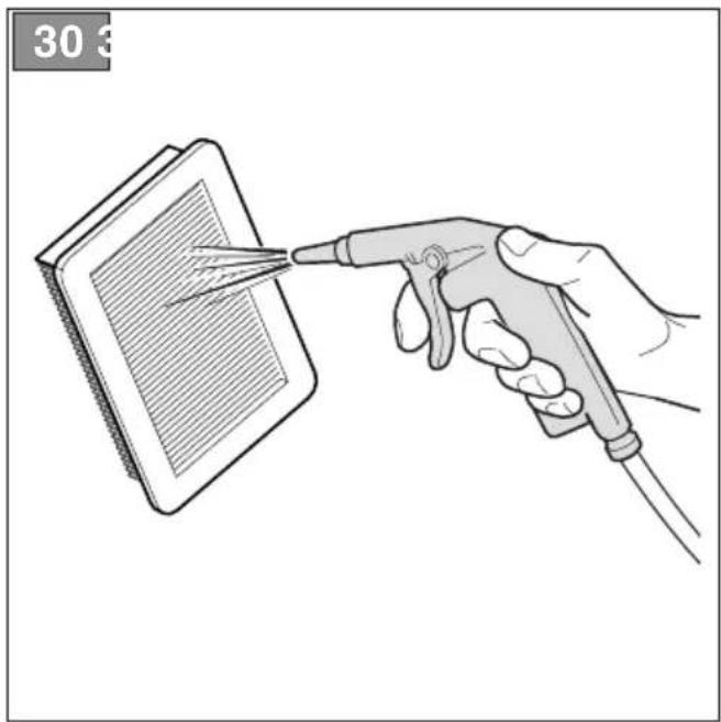
- unscrew the screws (Fig. 29.B), remove the cover (Fig. 29.A) and remove the filter element (Fig.29.C);
- blow compressed air from the inside to remove dust and debris (Fig. 30)
- refit the filter element (Fig. 29.C) and the cover (Fig. 29.A); then tighten the screws (Fig.29.B);
- Type II
To clean the filter:
- unscrew the knob (Fig. 29.B), remove the cover (Fig. 29.A) and remove the filter element (Fig.29.C);
- blow compressed air from the inside to remove dust and debris (Fig. 30)
- refit the filter element (Fig. 29.C) and the cover (Fig. 29.A); then tighten the knob (Fig.29.D);
8.4 SPARK PLUG
Remove and clean the spark plug at regular intervals; remove any deposits with a wire brush (Fig. 31).
Check and reset the correct gap between the electrodes (Fig. 31).
Refit the spark plug and tighten it fully using the wrench supplied.
The spark plug must be replaced with one having similar characteristics if burnt electrodes or deteriorated insulation are found or after every 100 hours of operation.
8.5 CUTTING MEANS MAINTENANCE
When servicing the cutting means, bear in mind that it can still move even if the spark plug cable been disconnected.
Cutting means displaying the code indicated on the Technical Data table should only be used on this machine.
Given product evolution, the cutting means mentioned in the "Technical Data" table may be replaced in time with others having similar interchangeable and operating safety features.
Do not touch the cutting means until the spark plug cable has been disconnected and the cutting means is completely stationary.
⚠️ Wear protective gloves.
8.5.1 Blade sharpening/balancing
⚠ For safety reasons, sharpening and balancing should be performed by an Authorised Service Centre with suitable skills and equipment for the job; without risking any damage to the blade which would make it unsafe when used.
3 point, 4 point and 8 point blades can be used on both sides. When one side of the points is worn, the blade can be turned and the other side used. When both sides of the points are worn, have them sharpened.
The saw blade is not reversible and therefore should only be used on one side.
8.5.2 Blade replacement
The blade must never be repaired, but must be replaced as soon as signs of breaking are noted or the sharpening limit is exceeded.
For replacement procedures, see sections 4.5.3 and 4.5.4.
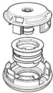
8.5.3 Replacing the cutting line head
- Type I
Follow the sequence shown in (Fig. 33).
- Type II
Cut the new line to the indicated length (Fig. 34.A).
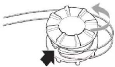
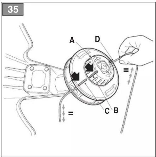
- Rotate the winding knob (Fig. 35.A) to align the reference on the knob (Fig. 35.B) with the reference on the head body (Fig. 35.C).
- Insert one end of the line (Fig. 35.D) in one of the two output holes and pass the line through the opposite hole.
- Align the lines that exit the two holes evenly.
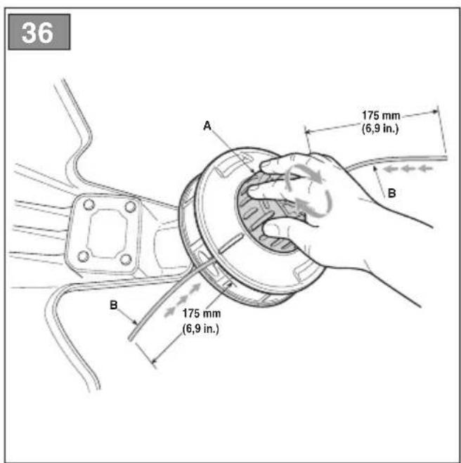
- Turn the winding knob (Fig. 36.A) following the direction of the arrows to wind the line, being careful to leave about 175 mm from both holes (Fig. 36.B).
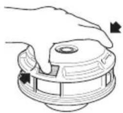
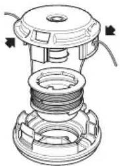
If old line is left in the head or if broken inside it, remove as described below:
- Press the tabs on the sides of the cutting line head, where marked "PUSH" (Fig. 37.A), and detach the lower part of the head (Fig. 37.B);
- Remove the line left inside;
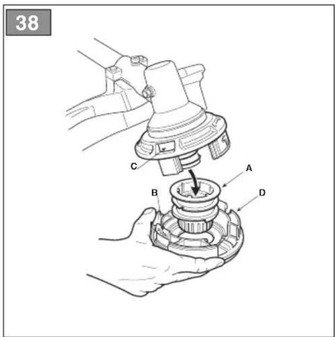
- replace the reel (Fig. 38.A) in its housing;
- Close the head by fastening the tabs (Fig. 38.B) in the slots (Fig. 38.C), pushing them fully in until they click to lock the bottom part of the head (Fig. 38.D) in place.
8.6 SHARPENING THE WIRE CUTTING BLADE
- Remove the wire cutter blade (Fig.32.A) from the guard (Fig.32.B) by unscrewing the screw (Fig. 32.C).
- Secure the wire cutting blade in a vice (Fig. 32.A) and sharpen it using a flat file, being careful to retain the original cutting angle;.
- Refit the wire cutter blade (Fig.32.A) on the guard (Fig. 32.B).
8.7 ADJUSTING IDLE SPEED
⚠️ If the cutting means moves with the engine idling, contact your dealer for the correct motor adjustment:
8.8 CARBURETTOR
The carburettor is set in the factory to obtain maximum performance in every use situation, with minimal emission of harmful gases, in compliance with current regulations.
In the event of poor performance, contact your Authorised Service for a carburettor and engine check.
9. STORAGE
IMPORTANT The safety regulations to follow for putting into storage are described in paragraph 2.4. Strictly comply with these instructions to avoid serious risks or hazards.
When the machine must be stored for a period of more than 2-3 months, certain steps must be taken to avoid difficulties when resuming work or permanent damage to the engine.
Before storing the machine:
- Empty the fuel tank outdoors and when the engine is cold.
-
Start the engine and leave it running at idle until it stops in order to consume all the fuel left in the carburettor.
-
Wait for the engine to cool.
- Remove the spark plug cap (Fig. 19.H).
- Clean the machine thoroughly.
- Check the machine for any damage. If necessary, contact the authorised service centre.
-
Store the machine:
-
in a dry place;
– protected from inclement weather;
– with the blade guard correctly mounted;
– in a place out of children's reach; - making sure that keys or tools used for maintenance are removed.
When starting up the machine again, prepare the machine as indicated in section 6. "Using the machine".
10. HANDLING AND TRANSPORT
When handling or transporting the machine, always:
- Stop the machine.
- Remove the spark plug cap (Fig. 19.H).
- Wear heavy-duty work gloves.
- When the cutting means has halted, fit the blade guard;.
- Only hold the machine using the hand grips and position the cutting means in the opposite direction to that used during operations.
When transporting the machine on a vehicle, always:
- position it so that it does not cause a hazard to anyone;
- fasten firmly to the device of transport using ropes or chains to prevent it from tipping over causing damage and fuel leaks.
11. ASSISTANCE AND REPAIRS
This manual provides all the necessary information to run the machine and for correct basic maintenance operations which can be performed by the user. Any regulations and maintenance operations not described herein must be carried out by your Dealer or Authorised Service Centre, which have the necessary knowledge and equipment to ensure that the work is carried out correctly, maintaining the correct degree of safety and the original operating conditions of the machine.
Any operations performed in unauthorised centres or by unqualified persons will totally invalidate the Warranty and all obligations and responsibilities of the Manufacturer.
- Only Authorised Service Centres can carry out guaranteed repairs and maintenance.
- The Authorised Service Centres only use genuine spare parts. Genuine spare parts and attachments have been designed specifically for machines.
- Non-genuine spare parts and accessories are not approved. Use of non-genuine spare parts and accessories cause the warranty to be voided.
- It is advisable to send your machine once a year to an Authorised Service Centre for servicing, assistance and safety device inspection.
12. WARRANTY COVERAGE
The warranty covers all material and manufacturing defects. The user must follow all the instructions provided in the accompanying documentation.
The warranty does not cover damage caused by:
- Failure to become familiar with the documentation accompanying the machine.
- Carelessness.
- Incorrect or prohibited use or assembly.
- Use of non-genuine spare parts.
- Use of attachments not supplied or not approved by the manufacturer.
The warranty does not cover:
- Normal wear and tear of consumables, such as cutting means, safety bolts.
• Normal wear and tear.
The purchaser is protected by his or her own national legislation. The purchaser's rights under the national laws or his or her own country are not in any way restricted by this warranty.
- MAINTENANCE TABLE
| Frequency | Intervention | |||||||||||||
| MACHINE ENGINE | ||||||||||||||
| Check all fasteners (see chap. 7.5) | Safety checks/ Controls verification (see chap. 6.2) | General cleaning and verification (see chap. 7.4) | Angle transmission and flexible tube lubrication (see chap. 8.1, 8.2) | Fuel level check/ top-up (see chap. 7.3) | General cleaning and verification (see chap. 7.4) | Air filter cleaning (see chap. 8.3) | Air filter replacement (see chap. 8.3) | Spark plug cleaning (see chap. 8.4) | Spark plug replacement (see chap. 8.4) | Tightening of the muffler screws * | Fuel filter replacement * | Cylinder exhaust port and cylinder wings* cleaning | ||
| Before each use | √ √ | √ √ | √ | |||||||||||
| 15 hours | √ | |||||||||||||
| 30 hours | √ √ | √ √ | ||||||||||||
| 45 hours | √ √ | √ | ||||||||||||
| 60 hours | √ √ | √ | ||||||||||||
| 75 hours | √ √ | √ | ||||||||||||
| 90 hours | √ √ | √ | ||||||||||||
| 105 hours | √ √ | √ √ | √ √ | |||||||||||
| 120 hours | √ √ | √ | ||||||||||||
| 135 hours | √ √ | √ | ||||||||||||
| 150 hours | √ √ | √ √ | ||||||||||||
| 165 hours | √ √ | √ | ||||||||||||
| 180 hours | √ √ | √ | ||||||||||||
| 195 hours | √ √ | √ | ||||||||||||
| 210 hours | √ √ | √ √ | √ √ | |||||||||||
| 225 hours | √ √ | √ | ||||||||||||
| 240 hours | √ √ | √ | ||||||||||||
| 255 hours | √ √ | √ √ | ||||||||||||
| 270 hours | √ √ | √ | ||||||||||||
| 280 hours | √ √ | √ | ||||||||||||
| 300 hours | √ √ | √ | ||||||||||||
* Interventions that must be carried out by your Dealer or by an Authorised Service Centre
14. TROUBLESHOOTING
| PROBLEM PROBABLE CAUSE SOLUTION | ||
| 1. The engine does not start or does not keep running | Incorrect starting procedure. Follow the instructions (see Section 6.3) | |
| Dirty spark plug or incorrect electrode gap | Check the spark plug (see section 8.4). | |
| Clogged air filter Clean and/or replace the filter (see section 8.3). | ||
| Carburation fault Contact your Authorised Service Centre. | ||
| 2. The engine starts but has little power. | Clogged air filter Clean and/or replace the filter (see section 8.3). | |
| Carburation fault Contact your Authorised Service Centre. | ||
| 3. The engine has irregular operation or has no power under load | Dirty spark plug or incorrect electrode gap | Check the spark plug (see section 8.4). |
| Carburation fault Contact your Authorised Service Centre. | ||
| 4. The engine causes excessive fumes | Incorrect composition of the fuel blend prepare the fuel blend in accordance with the instructions (see section 7.2) | |
| Carburation fault Contact your Authorised Service Centre. | ||
| 5. Engine flooding The starter knob was operated repeatedly with the starter inserted, | Remove the spark plug (Fig. 31) and gently pull the starter rope knob (Fig. 19.I) to eliminate excess fuel; then dry the spark plug electrodes and reassemble on the engine. | |
| 6. The cutting means moves when the engine is idling | Incorrect adjustment of carburation | Contact your Authorised Service Centre. |
| 7. Unusual machine vibrations | Damaged or loose parts. Stop the machine and disconnect the spark plug cable (Fig. 19.H.), inspect for possible damage. Check for and tighten any loose parts. All checks, replacements or repairs should be carried out by your authorised service centre. | |
| 8. The machine has struck a foreign body | Damaged or loose parts. Stop the machine and disconnect the spark plug cable (Fig. 19.H.), inspect for possible damage. Check for and tighten any loose parts. All checks, replacements or repairs should be carried out by your authorised service centre. | |
If problems persist after implementing the solution, contact your Dealer.
D. Lgs.262/2002, ANNEX V (Italy)
UK DECLARATION OF CONFORMITY
(Supply of Machinery (Safety) Regulations 2008, S.I. 2008 No. 1597, Annex II, part A)
- The company: ST. S.p.A. – Via del Lavoro, 6 – 31033 Castelfranco Veneto (TV) – Italy
- Hereby declares under its own responsibility that the machine:
portable hand-held powered brush-cutter (grass cutting)
a) Homologation type: TR 625 J
c) Serial number: 22A••TRB000001 ÷ 99L••TRB999999
d) Engine: petrol
- Conforms to UK Regulations:
• S.I. 2008/1597 - Supply of Machinery (Safety) Regulations 2008
- S.I. 2001/1701 - Schedule 8 - Noise Emission in the Environment by Equipment for use Outdoors Regulations 2001
e) Notified body: /
• S.I. 2016/1091 - Electromagnetic Compatibility Regulations 2016
- S.I. 2012/3032 - The Restriction of the Use of Certain Hazardous Substances in Electrical and Electronic Equipment Regulations 2012
- Reference to harmonised standards:
EN ISO 11806-1:2011
EN ISO 14982:2009
EN IEC 63000:2018
g) Measured sound power level: 109,1 dB(A)
h) Guaranteed sound power level: 112 dB(A)
i) Cutting width: 38 cm
n) Person authorised to compile the technical file:
ST. S.p.A.
Via del Lavoro, 6
31033 Castelfranco Veneto (TV) - Italia
o) Castelfranco Veneto, 01/10/2022 CEO Stiga Group
Sean Robinson

UK Importer:
STIGA LTD
Unit 8, Bluewater Estate Plympton,
Devon, PL7 4JH, England

D. Lgs.262/2002, ANNEX V (Italy)
UK DECLARATION OF CONFORMITY
(Supply of Machinery (Safety) Regulations 2008, S.I. 2008 No. 1597, Annex II, part A)
- The company: ST. S.p.A. – Via del Lavoro, 6 – 31033 Castelfranco Veneto (TV) – Italy
- Hereby declares under its own responsibility that the machine:
portable hand-held powered brush-cutter (grass cutting)
a) Homologation type: BC 625 - BC 625 J - BC 625 D
c) Serial number: 22A••TRB000001 ÷ 99L••TRB999999
d) Engine: petrol
- Conforms to UK Regulations:
• S.I. 2008/1597 - Supply of Machinery (Safety) Regulations 2008
- S.I. 2001/1701 - Schedule 8 - Noise Emission in the Environment by Equipment for use Outdoors Regulations 2001
e) Notified body: /
• S.I. 2016/1091 - Electromagnetic Compatibility Regulations 2016
- S.I. 2012/3032 - The Restriction of the Use of Certain Hazardous Substances in Electrical and Electronic Equipment Regulations 2012
- Reference to harmonised standards:
EN ISO 11806-1:2011
EN ISO 14982:2009
EN IEC 63000:2018
g) Measured sound power level: 110,1 dB(A)
h) Guaranteed sound power level: 112 dB(A)
j) Net power installed: 1,0 kW
n) Person authorised to compile the technical file:
ST. S.p.A.
Via del Lavoro, 6
31033 Castelfranco Veneto (TV) - Italia
o) Castelfranco Veneto, 01/10/2022 CEO Stiga Group
Sean Robinson

UK Importer:
STIGA LTD
Unit 8, Bluewater Estate Plympton,
Devon, PL7 4JH, England

D. Lgs.262/2002, ANNEX V (Italy)
UK DECLARATION OF CONFORMITY
(Supply of Machinery (Safety) Regulations 2008, S.I. 2008 No. 1597, Annex II, part A)
- The company: ST. S.p.A. – Via del Lavoro, 6 – 31033 Castelfranco Veneto (TV) – Italy
- Hereby declares under its own responsibility that the machine:
portable hand-held powered brush-cutter (grass cutting)
a) Homologation type: BC 536 - BC 536 D - BC 636 - BC 636 D
c) Serial number: 22A••TRB000001 ÷ 99L••TRB999999
d) Engine: petrol
- Conforms to UK Regulations:
• S.I. 2008/1597 - Supply of Machinery (Safety) Regulations 2008
- S.I. 2001/1701 - Schedule 8 - Noise Emission in the Environment by Equipment for use Outdoors Regulations 2001
e) Notified body: /
• S.I. 2016/1091 - Electromagnetic Compatibility Regulations 2016
- S.I. 2012/3032 - The Restriction of the Use of Certain Hazardous Substances in Electrical and Electronic Equipment Regulations 2012
- Reference to harmonised standards:
EN ISO 11806-1:2011
EN ISO 14982:2009
EN IEC 63000:2018
g) Measured sound power level: 108,67 dB(A)
h) Guaranteed sound power level: 113 dB(A)
j) Net power installed: 1,2 kW
n) Person authorised to compile the technical file:
ST. S.p.A.
Via del Lavoro, 6
31033 Castelfranco Veneto (TV) - Italia
o) Castelfranco Veneto, 01/10/2022 CEO Stiga Group
Sean Robinson

UK Importer:
STIGA LTD
Unit 8, Bluewater Estate Plympton,
Devon, PL7 4JH, England

D. Lgs.262/2002, ANNEX V (Italy)
| BC 546 - BC 546 D - BC 646 - BC 646 F |
| BC 646 D - BC 646 DX |
| g) Livello di potenza sonora misurato: | 97,64 dB(A) | 100 dB(A) |
| h) Livello di potenza sonora garantito: | 113 dB(A) | 113 dB(A) |
| j) Potenza netta installata: | 1,5 kW | 1,5 kW |
UK DECLARATION OF CONFORMITY
(Supply of Machinery (Safety) Regulations 2008, S.I. 2008 No. 1597, Annex II, part A)
- The company: ST. S.p.A. – Via del Lavoro, 6 – 31033 Castelfranco Veneto (TV) – Italy
- Hereby declares under its own responsibility that the machine:
portable hand-held powered brush-cutter (grass cutting)
a) Homologation type: BC 546 - BC 546 D - BC 646 - BC 646 D - BC 646 DX - BC 646 F
c) Serial number: 22A••TRB000001 ÷ 99L••TRB999999
d) Engine: petrol
- Conforms to UK Regulations:
• S.I. 2008/1597 - Supply of Machinery (Safety) Regulations 2008
- S.I. 2001/1701 - Schedule 8 - Noise Emission in the Environment by Equipment for use Outdoors Regulations 2001 e) Notified body: /
• S.I. 2016/1091 - Electromagnetic Compatibility Regulations 2016
- S.I. 2012/3032 - The Restriction of the Use of Certain Hazardous Substances in Electrical and Electronic Equipment Regulations 2012
- Reference to harmonised standards:
EN ISO 11806-1:2011
EN ISO 14982:2009
EN IEC 63000:2018
BC 546 - BC 546 D - BC 646 - BC 646 F BC 646 D - BC 646 DX
| g) Measured sound power level: | 97,64 dB(A) | 100 dB(A) |
| h) Guaranteed sound power level: | 113 dB(A) | 113 dB(A) |
| j) Net power installed: | 1,5 kW | 1,5 kW |
n) Person authorised to compile the technical file:
ST. S.p.A.
Via del Lavoro, 6
31033 Castelfranco Veneto (TV) - Italia
o) Castelfranco Veneto, 01/10/2022 CEO Stiga Group
Sean Robinson

UK Importer: STIGA LTD
Unit 8, Bluewater Estate Plympton,
Devon, PL7 4JH, England

D. Lgs.262/2002, ANNEX V (Italy)
| BC 556 - BC 556 D - BC 656 - BC 656 DX |
| BC 656 D |
| g) Livello di potenza sonora misurato: | 97,64 dB(A) | 110,34 dB(A) |
| h) Livello di potenza sonora garantito: | 113 dB(A) | 113 dB(A) |
| j) Potenza netta installata: | 1,7 kW | 1,7 kW |
UK DECLARATION OF CONFORMITY
(Supply of Machinery (Safety) Regulations 2008, S.I. 2008 No. 1597, Annex II, part A)
- The company: ST. S.p.A. – Via del Lavoro, 6 – 31033 Castelfranco Veneto (TV) – Italy
- Hereby declares under its own responsibility that the machine:
portable hand-held powered brush-cutter (grass cutting)
a) Homologation type: BC 556 - BC 556 D - BC 656 - BC 656 D - BC 656 DX
c) Serial number: 22A••TRB000001 ÷ 99L••TRB999999
d) Engine: petrol
- Conforms to UK Regulations:
• S.I. 2008/1597 - Supply of Machinery (Safety) Regulations 2008
- S.I. 2001/1701 - Schedule 8 - Noise Emission in the Environment by Equipment for use Outdoors Regulations 2001
e) Notified body: /
• S.I. 2016/1091 - Electromagnetic Compatibility Regulations 2016
- S.I. 2012/3032 - The Restriction of the Use of Certain Hazardous Substances in Electrical and Electronic Equipment Regulations 2012
- Reference to harmonised standards:
EN ISO 11806-1:2011
EN ISO 14982:2009
EN IEC 63000:2018
| BC 556 - BC 556 D - BC 656 - BC 656 DX |
| BC 656 D |
| g) Measured sound power level: | 97,64 dB(A) | 110,34 dB(A) |
| h) Guaranteed sound power level: | 113 dB(A) | 113 dB(A) |
| j) Net power installed: | 1,7 kW | 1,7 kW |
| n) Person authorised to compile the technical file: | ST. S.p.A.Via del Lavoro, 631033 Castelfranco Veneto (TV) - Italia |
o) Castelfranco Veneto, 01/10/2022 CEO Stiga Group
Sean Robinson

UK Importer: STIGA LTD
Unit 8, Bluewater Estate Plympton,
Devon, PL7 4JH, England

| FR (Traduction de la notice originale)Déclaration CE de Conformité(Directive Machines 2006/42/CE, Annexe II, partie A)1. La Société2. Déclare sous sa propre responsabilité que la machine : Débroussailleuse portative à moteur, coupe du gazona) Type / Modèle de Basec) Série d) Moteur essence3. Est conforme aux prescriptions des directives :e) Organisme de certification4. Renvoi aux Normes harmoniséesg) Niveau de puissance sonore mesuréh) Niveau de puissance sonore garantij) Puissance nette installéen) Personne habilitée à établir le Dossier Technique :o) Lieu et Date | EN (Translation of the original instruction)EC Declaration of Conformity(Machine Directive 2006/42/EC, Annex II, part A)1. The Company2. Herby declares under its own responsibility that the machine: portable hand-held powered brush-cutter, grass cuttinga) Type / Base Modelc) Serial numberd) Engine: petrol3. Conforms to directive specifications:e) Certifying body4. Reference to harmonised Standardsg) Sound power level measuredh) Sound power level guaranteedj) Net power installedn) Person authorised to create the Technical Folder:o) Place and Date | DE (Übersetzung der Originalbetriebsanleitung)EG-Konformitätserklärung(Maschinenrichtlinie 2006/42/EG, Anhang II, Teil A)1. Die Gesellschaft2. Erklärt auf eigene Verantwortung, dass die Maschine: Motorbetriebener Freischneider / rasenschnitta) Typ / Basismodellc) Seriennummerd) Verbrennungsmotor3. Den Anforderungen der folgenden Richtlinien entspricht:e) Zertifizierungsstelle4. Bezugnahme auf die harmonisierten Normeng) Gemessener Schallleistungspegelh) Garantierter Schallleistungspegelj) Installierte Nettoleistungn) Zur Verfassung der technischen Unterlagen befugte Person:o) Ort und Datum |
| NL (Vertaling van de oorspronkelijke gebruiksaanwijzing)EG-verklaring van overeenstemming(Richtlijn Machines 2006/42/CE, Bijlage II, deel A)1. Het bedrijf2. Verklaart onder zijn eigen verantwoordelijkheid dat de machine: Met de hand draagbare bosmaaier met motor / grasmaaiera) Type / Basismodelc) Serienummerd) benzinemotor3. Voldoet aan de specificaties van de richtlijnen:e) Certificatie-instituut4. Verwijzing naar de Geharmoniseerde normeng) Gemeten niveau van geluidsvermogenh) Gegarandeerd niveau van geluidsvermogenj) Netto geïnstalleerd vermogenn) Bevoegd persoon voor het opstellen van het Technisch Dossiero) Plaats en Datum | ES (Traducción del Manual Original)Declaración de Conformidad CE(Directiva Máquinas 2006/42/CE, Anexo II, parte A)1. La Empresa2. Declara bajo su propia responsabilidad que la máquina: Desbrozadora de motor portátil manualmente / corte hierbaa) Tipo / Modelo Basec) Matriculad) motor de explosión3. Cumple con las especificaciones de las directivas:e) Ente certificador4. Referencia a las Normas armonizadasg) Nivel de potencia sonora medidoh) Nivel de potencia sonora garantizadoj) Potencia neta instaladan) Persona autorizada a realizar el Manual Técnico:o) Lugar y Fecha | PT (Tradução do manual original)Declaração CE de Conformidade(Diretiva de Máquinas 2006/42/CE, Anexo II, parte A)1. A Empresa2. Declara sob a própria responsabilidade que a máquina: Roçadora manual motorizada / corte da relvaa) Tipo / Modelo Basec) Matriculad) motor a explosão3. É conforme às especificações das diretivas:e) Órgão certificador4. Referência às Normas harmonizadasg) Nível medido de potência sonorah) Nivel garantido de potência sonoraj) Potência líquida instaladan) Pessoa autorizada a elaborar o Caderno Técnicoo) Local e Data |
| EL (Metaáfραση του πρωτοτύπου των οδηγιών χρήσης)ΕΚ-Δήλωση συμμόρφωσης(Οδηγία Μηχανών 2006/42/CE, Παράρτημα II, μέρος A)1. Η Έταιρία2. Δηλώνει υπεύθυνα ότι η μηχανή: Форητό χειροκατευθυνόμενο θαμνοκοπτικό βενζίνης / κοπτή της χλόηςa) Τύπος / Βαστικό Μοντέλοc) Αριθμος μητρώουd) κινητήρας εσωτερικής ανάφλεξης3. Συμμορφώνεται με τις προδιαγραφές της οδηγίας:e) Οργανισμός πιστοποίησης4. Αναφορά στους Κανονισμούς εναρμόνισηςg) Στάθμη μέτρησης ακουστικής ισχύοςh) Στάθμη εγγυημένης ακουστικής ισχύοςj) Καθαρή εγκαταστημένη ισχύςn) Εξουσιοδοτημένο άτομο για την κατάρτιση του Τεχνικού Φυλλαδίου:o) Τόπος και Χρόνος | TR (Orijinal Talimatlann Tercümesi)AT Uygunluk Beyani(2006/42/CE Makine Direktifi, Ek II, bölüm A)1. Şirket2. Şahsi sorumluluğu altında aşağıdaki makinenin: Elde taşınabilir motorlu çalı bığme makinesi / çim kesimia) Tip / Standart modelc) Sicil numarasıd) patlamali motor3. Aşağıdaki direktiflerin özelliklerine uygun olduğunu beyan etmektedir:e) Sertifikalandiran kurum4. Harmonize standartlara atifg) Ölçülen ses güç seviyesih) Garanti edilen ses güç seviyesij) Kurulu net güçn) Teknik Dosyayı oluşturmaya yetkili kişi:o) Yer ve Tarih | MK (Превод на оригиналните упатства)Декларација за усогласеност со ЕУ(Директива за машини 2006/42/CE, Анекс II, дел A)1. Компанијата2. изјавува со целосна лична одговорност дека следната машина:Поткаструвач за грмушки / косење треваа) Тип / основен моделв) етикетаг) мотор: мотор со согорување3. Усогласено со спецификациите според директивите:д) тело за сертификација4. Референци за усогласени нормативие) Акустички притисокж) измерено ниво на звучна мо́кностз) Ниво на гарантирана звучна мо́кностн) овластено лице за составување на Техничката брошурао) место и датум |
| NO (Oversettelse av original bruksanvisning)EF- Samsvarserklæring (Maskindirektiv 2006/42/EF, Vedlegg II, del A)1. Firmaet2. Erklærer på eget ansvar at maskinen: Bærbar, håndholdt motordrevet ryddesag / gressklippinga) Type / Modellc) Serienummerd) Forbrenningsmotor3. Oppfyller kravene i direktivene:e) Sertifiseringsorgan4. Henvisning til harmoniserte standarderg) Målt lydeffektniváh) Garantert lydeffektniváj) Installert nettoeffektn) Person som har fullmakt til á utferdige teknisk dokumentasjon:o) Sted og dato | SV Översättning av bruksanvisning i original)EG-försäkran om överensstämmelse (Maskindirektiv 2006/42//EG, bilaga II, de la)1. Företaget2. Försäkrar på eget ansvar att maskinen Motordriven bärbar manuell röjsåg / gräsklippingna) Typ / Basmodellc) Serienummerd) förbränningsmotor3. Överensstämmer med föreskrifterna i direktivete) Intygsorgan _Anmält organ4. Referens till harmoniserade standarderg) Uppmätt ljudeffektniváh) Garanterad ljudeffektniváj) Installerad nettoeffektn) Auktoriserad person för upprättandet av den tekniska dokumentationen:o) Ort och datum | DA (Oversættelse af den originale brugsanvisning)EF-overensstemmelseserklæring (Maskindirektiv 2006/42/EF, bilag II, del A)1. Firmaet2. Erklærer på eget ansvar, at maskinen: Bærbar, håndholdt motordreven buskrydder / klipning af græsseta) Type / Modelc) Serienummerd) forbrændingsmotor3. Er i overensstemmelse med specifikationerne ifelge direktiverne:e) Certificeringsorgan4. Henvisning til harmoniserede standarderg) Målt lydeffektniveauh) Garanteret lydeffektniveauj) Installeret nettoeffektn) Person, der har bemyndigelse til at udarbejde det tekniske dossier:o) Sted og dato |
| FI (Alkuperäisten ohjeiden käännös)EY-VAATIMUSTENMUKAISUUSVAKUUTUS (Konedirektiivi 2006/42/EY, Liite II, osa A)1. Yritys2. Vakuuttaa omalla vastuullaan, että kone: Käsin kannateltava moottorikäyttöinen raivaussaha / ruohonleikkuua) Tyyppi / Perusmallic) Sarjanumerod) räjähdysmoottori3. On yhdenmukainen seuraavien direktiivien asettamien vaatimusten kanssa:e) Sertifointiyritys4. Viittaus harmonisoituihin standardeihing) Mitattu äänitehotasoh) Taattu äänitehotasoj) Asennettu nettoteholmastointikone-Niittokone / maan ilmaus/haraus n) Teknisten asiakirjojen laatimiseen valtuutettu henkilö:o) Paikka ja päivämäärä | CS Překlad původního návodu k používání)ES – Prohlášení o shodě (Směrnice o Strojních zařízeních 2006/42/ES, Přiloha II, část A)1. Společnost2. Prohlášuje na vlastní odpovědnost, že stroj: Ručné přenosný motorový křovinořez / sekačka na trávua) Typ / Základní modelc) Výrobní číslod) spalovací motor3. Je ve shodě s nařízeními směrnic:e) Certifikační orgán4. Odkazy na Harmonizované normyg) Naměřená úroveň akustického výkonuh) Zaručená úroveň akustického výkonuj) Čistý instalovaný výkonn) Osoba autorizovaná pro vytvoření Technického spisu:o) Místo a Datum | PL (Tlumaczenie instrukcji oryginalnej)Deklaracja zgodności WE (Dyrektywa maszynowa 2006/42/WE, Załącznik II, część A)1. Spółka2. Oświadczna na własną odpowiedzialność, že maszyna: Ręczna, przenośna kosa spalinowa do zarośli/ cięcie trawy a) Typ / Model podstawowyc) Numer seryjnyd) silnik o zapłonie iskrowym3. Spełnia podstawowe wymogi następujących Dyrektyw:e) Jednostka certyfikująca4. Odniesienie do Norm zharmonizowanychg) Zmierzony poziom mocy akustycznejh) Gwarantowany poziom mocy akustycznejj) Moc zainstalowana netton) Osoba upoważniona do zredagowania Dokumentacji technicznej:o) Miejscowość i data |
| HU (Eredeti használati utasítás fordítása)EK-megfelelőségi nyilatkozata (2006/42/EK gépirányely, II. melléklet "A" rész)1. Alulirott Vállalat2. Felelősségének teljes tudatában kijelenti, hogy az alábbi gép: Hordozható motoros kézi bozótirtó / fünyirásaa) Típus / Alaptípusc) Gyártási számd) robbanómotor3. Megfelel az alábbi irányelvekelőírásainak:e) Tanúsító szerv4. Hivatkozás a harmonizált szabványokrag) Mért zajteljesítmény szinth) Garantált zajteljesítmény szintj) Nüttó beépített teljesítményn) Műszaki Dosszié szerkesztésérefelhatalmazott személy:o) Helye és ideje | RU (Перевод оригинальных инструкций)Декларация соответствия нормам EC (Директива о машинном оборудовании 2006/42/EC, Приложение II, часть A)1. Предприятие2. Заявляет под собственную ответственность, что машина: Портативный моторизованный кусторез / стрижка газонаа) Тип / Базовая модельс) Паспортd) двигатель внутреннего сгорания3. Соответствует требованиям следующих директив:e) Сертифицирующий орган4. Ссылки на гармонизированные нормыg) Измеренный уровень звуковой мощностиh) Гарантируемый уровень звуковой мощностиj) Чистая установленная мощностьn) Лицо, уполномоченное на подготовку технической документации:o) Место и дата | HR (Prijevod originalnih uputa)EK Izjava o sukladnosti (Direktiva 2006/42/EZ o strojevima, dodatak II, dio A)1. Tvrtka:2. pod vlastitom odgovornošću izjavljuje da je stroj: Prijenosni motorni ručno upravljani čistač šikare / košenje travea) Vrsta / Osnovni modelc) Matični brojd) motor s unutarnjim izgaranjem3. sukladan s temeljnim zahtjevima direktiva:e) Certifikacijsko tijelo4. Primijenjene su slijedeće harmonizirane norme:g) Izmjerena razina zvučne snageh) Zajamčena razina zvučne snagej) Neto instalirana snagan) Osoba ovlaštena za pravljenje Tehničke datoteke:o) Mjesto i datum |
| SL (Prevod izvirnih navodil)ES izjava o skladnosti(Direktiva 2006/42/ES) , priloga II, del A)1. Družba2. pod lastno odgovornostjo izjavlja, da je stroj: Prenosna motorna kosa / košnja travea) Tip / osnovni modelc) Serijska številkad) motor z notranjim izgorevanjem3. Skladen je z določili direktiv :e) Ustanova, ki izda potrdilo4. Sklicevanje na usklajene predpiseg) Izmerjen nivo zvočne močih) Zagotovljen nivo zvočne močij) Neto instalirana močn) Oseba, pooblaščena za sestavo tehničneknjižice:o) Kraj in datum | BS (Prijevod originalnih uputa)EZ izjava o sukladnosti(Direktiva o mašinama 2006/42/EZ, Prilog II, deo A)1. Firma2. Daje izjavu pod vlastitom odgovornošćuda je mašina: Ručna motorna trimer kosilica/Košenje trava) Tip / Osnovni modelc) Serijski brojd) motor s unutrašnjim izgaranjem3. sukladna s osnovnim zahtjevimadirektive:e) Certifikaciono tijelo4. Pozivanje na usklađene normeg) Izmjereni nivo zvučne snageh) Garantovani nivo zvučne snagej) Neto instalisana snagan) Osoba ovlaštena za izradu tehničkebrošure:o) Mjesto I datum | SK (Preklad pôvodného návodu na použitie)ES vyhlásenie o zhode(Šmernica o Strojných zariadeniach 2006/42/ES, Príloha II, čast' A)1. Spoločnosť2. Vyhlasuje na vlastnú zodpovednosť, že stroj: Ručne prenosný motorový krovinorez/kosačka na trávua) Typ / Základný modelc) Výrobné číslod) spal’ovací motor3. Je v zhode s nariadeniami smerníc:e) Certifikačný orgán4. Odkaz na Harmonizované normyg) Nameraná úroveň akustického výkonuh) Zaručená úroveň akustického výkonuj) Čistý inštalovaný výkonn) Osoba autorizovaná na vytvorenieTechnického spisu:o) Miesto a Dátum |
| RO ( Traducerea manualului fabricantului)CE -Declaratie de Conformitate(Directiva Mašini 2006/42/CE, Anexa II, partea A)1. Societatea2. Declará pe propria răspundere cămašina: Mašină de tălat arboret cu motorportabil manual/ tălat larbaa) Tip / Model de bazác) Număr de seried) motor cu combustie3. Este în conformitate cu specificațiiledirectivelor:e) Organism de certificare4. Referință la Standardele armonizateg) Nivel de putere sonoră măsurath) Nivel de putere sonoră garantatj) Putere netă instalatán) Persoană autorizată să întocmeascăDosarul Tehnico) Locul și Data | LT (Originalių instrukciju vertimas)EB atitikties deklaracija(Mašinų direktyva 2006/42/CE, Priedas II,dalls A)1. Bendrovė2. Prisiima atsakomybę, kad jrenginys:Nešlojama rankinė motorinė krūmapjovė /zăles plăušanaa) Tipas / Bazinis Modelisc) Serijos numerisd) vidaus degimo variklis3. Atitinka direktyvose pateiktasspecifikacijas:e) Sertifikavimo |staiga4. Nuoroda i suderintas Normasg) Išmatuotas garso galios lyglish) Užtikrlnamas garso gallos lyglsj) Instaliuota naudingoji galian) Autorizuotas asmuo sudaryti TechninęDokumentaclją:o) Vieta ir Data | LV (Instrukciju tulkojums no originălvalodas)EK atbilstības deklarācija(Direktiva 2006/42/EK par mašinăm,pleilkums II, daja A)1. Uznēmums2. Uznēmoties par to pilnu atbildību, paziņo,ka mašina: Ar pledzlņu aprikotalsrokturamais portatīvs krūmgrlezis / zălespļaušanaa) Tips / Băzes modelisc) Sērljas numursd) iekšdedzes motors3. Atbilst šädu direktīvu prasībām:e) Sertifikācijas lestāde4. Atsauce uz harmonizētiem standartiemg) Izmērītais skaņas intensitātes līmenish) Garantētais skaņas intensitātes līmenisj) Uzstādītā neto jaudan) Pilvarotais darbinieks, kas sagatavojatehnlsko dokumentāciju:o) Vieta un datums |
| SR (Prevod originalnih uputstval)EC deklaracija o usaglašenosti(Direktiva o mašlnama 2006/42/EC, Prilog II,deo A)1. Preduzeće2. Daje izjavu pod vlastitom odgovornošćuda je mašina: Ručna motorna trimerkosačica / košenje travea) Tip / Osnovni modelc) Serijski brojd) motor s unutrašnjim sagorevanjem3. u skladu s osnovnim zahtevima direktiva:e) Sertifikaciono telo4. Pozivanje na usklađene normeg) Izmereni nivo zvučne snageh) Garantovani nivo zvučne snagej) Neto instalisana snagan) Osoba ovlašćena za sastavljanjetehničke brošureo) Mesto i datum | BG (Превод на оригиналните инструкции)EO декларация за съответствие(Директива Машини 2006/42/EO,Приложение II, част A)1. Дружеството2. На собствена отговорност декларира,че машината: Преносим ръчен моторенхрасторез / rязане на треваa) Вид / Базисен моделв) Сериен номерг) мотор с вътрешно горене3. Е в съответствие със спецификата надирективите:д) Сертифициращ орган4. Базирано на хармонизираните нормиж) Ниво на измерена акустична мощности) Гарантирано ниво на акустичнамощностк) Нетна инсталирана мощностр) Лице, упълномощено да съставиТехническата Документация:o) Място и дата | ET (Algupārase kasutusjuhendi tõlge)EÜ vastavusdeklaratsioon(Maslnadirektliv 2006/42/EÜ, Lisa II, osa A)1. Firma2. Kinnitab omal vastutusel, et masin:Kăeskantav mootoriga võsalõlkur /muruniitjaa) Tüüp / Põhimudelc) Matrikkeld) Sisepõlemismootor3. Vastab direktiivide nõuetele:e) Kinnitav asutus4. Viide ühtlustatud standarditeleg) Möödetud helivõimsuse taseh) Garanteeritud helivõimsuse tasej) Installeeritud netovõimsusn) Tehnilise Lehe autoriseeritud koostaja:o) Koht ja Kuupäev |
EN • The content and images in this User Manual were produced expressly for ST. S.p.A. and are protected by copyright – any unauthorised reproduction or modification to the document, either partially or in full, is prohibited.
Type: