
KT 203 - Multimeter Kyoritsu - Free user manual and instructions
Find the device manual for free KT 203 Kyoritsu in PDF.


| Product Type | AC/DC Digital Clamp Meter |
| Model | KEWTECH KT203 |
| Brand | Kyoritsu |
| Display | Liquid crystal, maximum count 4199 |
| AC Current Ranges | 40.00A / 400.0A (auto-ranging, 50/60Hz) |
| DC Current Ranges | 40.00A / 400.0A (auto-ranging) |
| AC Voltage Ranges | 400.0V / 600V (auto-ranging, 50/60Hz) |
| DC Voltage Ranges | 400.0V / 600V (auto-ranging) |
| Resistance Range | 400.0Ω / 4000Ω (auto-ranging) |
| Continuity Check | Buzzer beeps below 50±35Ω |
| Data Hold Function | Freezes measured value on display |
| Sleep Function | Auto power-off after approx. 10 minutes |
| Overrange Indication | "OL." shown on display |
| Sample Rate | Approx. 2.5 times per second |
| Response Time | Approx. 2 seconds |
| Safety Standards | CAT III 300V AC, CAT II 600V AC/DC, pollution degree 2 |
| Overload Protection | AC current: 480A AC/DC for 10s; voltage: 720V AC/DC for 10s; resistance: 300V AC/DC for 10s |
| Power Source | Two R03 (DC1.5V) batteries |
| Current Consumption | Approx. 15mA max (ACA/DCA), 5mA max (ACV/DCV/Ω) |
| Dimensions | 187(L) x 68.5(W) x 38.5(D) mm |
| Weight | Approx. 200g (including batteries) |
| Conductor Size | Max 30mm diameter |
| Operating Temperature & Humidity | 0~40°C, up to 85% RH (non-condensing) |
| Storage Temperature & Humidity | -20~60°C, up to 85% RH (non-condensing) |
| Accessories | Test leads, two R03 batteries, instruction manual |
Frequently Asked Questions - KT 203 Kyoritsu
User questions about KT 203 Kyoritsu
0 question about this device. Answer the ones you know or ask your own.
Ask a new question about this device
Download the instructions for your Multimeter in PDF format for free! Find your manual KT 203 - Kyoritsu and take your electronic device back in hand. On this page are published all the documents necessary for the use of your device. KT 203 by Kyoritsu.
USER MANUAL KT 203 Kyoritsu
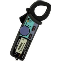
INSTRUCTION MANUAL AC/DC DIGITAL CLAMP METER KEWTECH KT203

Protective fingerguard (Barrier)
It is a part providing protection against electrical shock and ensuring the minimum required air and creepage distances.
Cap
Uncapped condition for CAT II environment Capped condition for CAT III/ IV environments The Cap should be firmly attached to the probes.
When the instrument and the test lead are combined and used together, whichever lower category either of them belongs to will be applied
- Features
● Safety design conforming to the following provisions of IEC61010.
Measurement category III 300V AC, pollution degree 2
Measurement category II 600V AC/DC, pollution degree 2
- Protected throughout by double or reinforced insulation, indicated the International Electrical Symbol "□" on the bottom of the instrument.
● Data hold switch for easy reading in dimly light or hard-to-read locations.
● "Sleep" feature to extend battery life.
- Beeper permits easy continuity check. - Provides a dynamic range of 4,000 counts full scale.
- Safety Warnings
● This instruction manual contains warnings and safety rules which must be observed by the user to ensure safe operation of the instrument and retain it in safe condition. Therefore, read through these operating instructions before using the instrument.
⚠ WARNING
- Read through and understand instructions contained in this manual before using the instrument
- Save and keep the manual handy to enable quick reference whenever necessary.
● The instrument is to be used only in its intended applications.
Understand and follow all the safety instructions contained in the manual.
Failure to follow the instructions may cause injury, instrument damage and/ordamage to equipment under test. Kyoritsu is by no means liable for any damage resulting from the instrument in contradiction to this cautionary note.
NOTE
The sleep feature automatically turns the instrument off in a certain period of time after the last switch operation. Therefore, the display may be blank with the function selector switch set to a position other than "OFF". To operate the instrument in this case, set the switch back to the "OFF" position, then to the desired position, or press any switch. If the display still blanks, the batteries are exhausted. Replace the batteries.
4-2 Checking Switch Setting and Operation
Make sure that the function selector switch is set to the correct position and the data hold switch is deactivated. Otherwise, desired measurement cannot be made.
5. Current Measurement
WARNING
- Do not make measurement on a circuit with a voltage higher than 600 V AC/DC. Otherwise, shock hazard or damage to the instrument or equipment under test may result.
- Transformer jaw tips are designed to minimize the possibility of shorting conductors in the circuit under test. If equipment under test has exposed conductive parts, however, extra precaution should be taken to avoid possible shorting.
- Do not make measurement with the battery compartment cover removed.
- Do not make current measurement with the test leads connected to the instrument.
- It is a part providing protection against electrical shock and ensuring the minimum required air and creepage distances. Keep your fingers and hands behind the barrier during measurement.
NOTE
- During current measurement, keep the transformer jaws fully closed. Otherwise, accurate measurement cannot be made. The maximum conductor size is 30 mm in diameter.
- When measuring a larger current, the transformer jaws may buzz. This does not affect the instrument's accuracy.
5-1 AC Current Measurement
(1) Set the function selector switch to the "ACA" position.
(2) Press the trigger to open the transformer jaws and clamp onto one conductor only.
(3) Take the reading on the display.
5-2 DC Current Measurement
(1) Set the function selector switch to the "DCA" position
(2) With the transformer jaws closed and without clamping them onto the conductor, press the 0 ADJ. Switch for more than 2 seconds to zero adjust the display. (less than 2 seconds: Data Hold Function operates.) The 0 ADJ. Switch is enabled only on DC 40A range.
(3) Press the trigger to open the transformer jaws and clamp onto one conductor only.
(4) Take the reading on the display.
The symbol indicated on the instrument means that the user must refer to related parts in the manual for safe operation of the instrument. Be sure to carefully read the instructions following each symbol in this manual.
⚠️DANGER is reserved for conditions and actions that are likely to cause serious or fatal injury. ⚠️WARNING is reserved for conditions and actions that can cause serious or fatal injury.
actions that can cause serious or fatal injury: CAUTION is reserved for conditions and actions that can cause minor injury or instrument damage. Following symbols are used on the instrument and in the instruction manual. Attention should be paid to each symbol to ensure your safety.
Refer to the instructions in the manual.
This symbol is marked where the user must refer to the instruction manual so as not to cause personal injury or instrument damage.
☐ Indicates an instrument with double or reinforced insulation.
Indicates that this instrument can clamp on
bare conductors when measuring a voltage corresponding to the applicable Measurement category, which is marked next to this symbol.
This instrument satisfies the marking requirement defined in the WEEE Directive (2002/96/EC). This symbol indicates separate
collection for electrical and electronic equipment. ↓ Indicates Earth.
△ DANGER
● Never make measurement on a circuit with voltage higher than 600 V AC/DC.
- Do not attempt to make measurement in the presence of flammable gasses, fumes, vapor or dust. Otherwise, the use of the instrument may cause sparking, which can lead to an explosion.
● Transformer jaws are made of metal and their tips are not insulated. Where equipment under test has exposed conductive parts, be especially careful to avoid the hazard of possible shorting.
● Never attempt to use the instrument if its surface or your hand is wet.
- Do not exceed the maximum allowable input of any measurement range.
● Never open the battery compartment cover when making measurement.
- Verify proper operation on a known source before use or taking action as a result indication of the instrument.
- Keep your fingers and hands behind the protective fingerguard during measurement.
WARNING
- Never attempt to make any measurement if any abnormal conditions are noted, such as broken case, cracked test leads and exposed metal part.
- Do not turn the function selector switch with plugged in test leads connected to the circuit under test.
- Do not install substitute parts or make any modification to the instrument. Return the instrument to your distributor for repair or recalibration
- Do not try to replace the batteries if the surface of the instrument is wet.
● Always switch off the instrument before opening the battery compartment cover for battery replacement.
- Stop using the test lead if the outer jacket is damaged and the inner metal or color jacket is exposed.
CAUTION
● Make sure that the function selector switch is set to the appropriate position before making measurement.
NOTE
When current flows from the upside to the underside of the instrument, the polarity of the reading is positive (+). Otherwise, the polarity of the reading is negative (-).
6. Voltage Measurement
⚠️ DANGER
- Never use the instrument on a circuit with a voltage higher than 600 VAC/DC. Otherwise, electric shock hazard or damage to the
- Instrument of the circuit under test may result. - Do not make measurement with the battery compartment cover removed.
- Keep your fingers and hands behind the protective fingerguard during measurement.
6-1 AC Voltage Measurement
(1) Set the function selector switch to the "ACV" position
(2) Plug the red test lead into the V/Ω terminal and the black test lead into the COM terminal.
(3) Connect the test lead prods to the circuit under test and take the reading on the display.
6-2 DC Voltage Measurement
(1) Set the function selector switch to the "DCV" position
(2) Plug the red test lead into the V/Ω terminal and the black test lead into the COM terminal.
(3) Connect the test lead prods to the circuit under test and take the reading on the display.
7. Resistance Measurement
⚠️ DANGER
● Always make sure that the circuit under test is powered off.
- Do not make measurement with the battery compartment cover removed.
- Keep your fingers and hands behind the protective fingerguard during measurement.
(1) Set the function selector switch to the / ·s " position
(2) Plug the red test lead into the V/Ω terminal and the black test lead into the COM terminal.
(3) Check that the display reads "OL." with the test lead prods shorted together, also check that the buzzer beeps and the display reads "O."
(4) Connect the test lead prods to the circuit under test and take the reading on the display. The buzzer beeps the reading is below 50 ± 35 .
● Always make sure to insert each plug of the test leads fully into the appropriate terminal on the instrument.
● Make sure to remove the test leads from the instrument before making current measurement
- Do not expose the instrument to the direct sun, extreme temperatures or dew fall
- Be sure to set the function selector switch to the "OFF" position after use. When the instrument will not be in use for a long period of time, place it in storage after removing the battery.
- Use a damp cloth and detergent for cleaning the instrument. Do not use abrasives or solvents
- This instrument isn't dust & water proofed. Keep away from dust and water.
Measurement categories (Over-voltage categories)
To ensure safe operation of measuring instruments, IEC 61010 establishes safety standards for various electrical environments, categorized as O to CAT IV, and called measurement categories.
Higher-numbered categories correspond to electrical
environments with greater momentary energy, so a measuring instrument designed for CAT III environments can endure greater momentary energy than one designed for CAT II.
- Circuits which are not directly connected to the mains power supply.
CAT II : Primary electrical circuits of equipment connected to an AC electrical outlet by a power cord
CAT III: Primary electrical circuits of the equipment
connected directly to the distribution panel, and feeders from the distribution panel to outlets.
CAT IV : The circuit from the service drop to the service entrance, and to the power meter and primary overcurrent protection device (distribution panel).
- Specifications
Measuring Ranges and Accuracy (at 22 + 5°C, 45.75% relative by
(at 25 ± 3°C, 45-75% relative humidity) AC Current (A) Auto-ranging (50/60Hz)
| Range | Measuring Range | Accuracy |
| 40A | 0-40.00A | ±3.0%rdg±8dgt |
| 400A | 15.0-299.9A | ±3.5%rdg±6dgt |
| 300.0-400.0A | ±4.0%rdg±6dgt |
DC Current (A) Auto-ranging
| Range | Measuring Range | Accuracy |
| 40A | 0-40.00A | ±3.0%rdg±8dgt |
| 400A | 15.0-299.9A | ±3.5%rdg±6dgt |
| 300.0-400.0A | ±4.0%rdg±6dgt |
AC Voltage (V) Auto-ranging (50/60Hz)
| Range | Measuring Range | Accuracy |
| 400V | 0-400.0V | ±2.0%rdg±5dgt |
| 600V | 150-600V |
DC Voltage (V) Auto-ranging
| Range | Measuring Range | Accuracy |
| 400V | 0-400.0V | ±1.5%rdg±5dgt |
| 600V | 150-600V |
Resistance(Ω /Continuity) Auto-ranging (Buzzer beeps below 50±35 Ω)
| Range | Measuring Range | Accuracy |
| 400 Ω | 0-400.0 Ω | ±2.0%rdg±5dgt |
| 4000 Ω | 150-4000 Ω |
- Operating System
Dual Integration
- Display
Liquid crystal display
(maximum count: 4199)
● Low Battery Warning
BAT" is shown on the display
NOTE
- When shorting the test lead prods together, the display may show a very small resistance instead of "0." This is the resistance of the test leads.
- If one of the test leads has an open, the display reads "OL."
8. Other Functions
8-1 Sleep Function
NOTE
The instrument still consumes small amount of battery power in the sleep mode. Make sure to set the function selector switch to the "OFF" position after use.
(1) Sleep Mode
This is a function to prevent the instrument from being left powered on in order to conserve battery life. This function causes the instrument to automatically enter the sleep (powered down) mode about 10 minutes after the last switch or button operation.
To exit the sleep mode, turn the function selector switch back to "OFF", then to any other position, or press any button.
(2) How to disable the sleep mode
To disable the sleep mode, Power the instrument on with the data hold switch pressed. "P.OFF" is shown on the display for about 3 seconds after the instrument is powered on.
To enable the sleep mode, power the instrument off, then power it on without pressing the data hold switch.
8-2 Data Hold Function
This is a function used to freeze the measured value on the display. Press the data hold switch to freeze the reading. The reading will be held regardless of subsequent changes in input. "■" is shown on the upper left corner of the display while the instrument is in the data hold mode.
To exit the data hold mode, press the data hold switch again.

NOTE
- If the instrument in the data hold mode enters the sleep mode, the data hold mode will be cancelled.
- At DC 40A range, if the data hold switch is pressed for more than 2 seconds, 0 ADJ. Function operates.
● Overrange Indication
"OL." is shown on the display
- Response Time
Approx. 2 seconds
- Sample Rate :
About 2.5 times per second
● Temperature and Humidity for Guranteed Accuracy: 23 ± 5^ , relative humidity up to 85% without condensation
● Operating Temperature and Humidity :
0\~40°C . relative humidity up to 85%
without condensation
● Storage Temperature and Humidity
-20\~60°C, relative humidity up to 85%
without condensation
● Power Source
Two R03 or equivalent(DC1.5V) batteries
● Current Consumption
Approx. 15mA max. (ACA, DCA Range)
Approx. 5mA max. (ACV, DCV, Ω Range)
- Sleep Function :
Automatically powered down in about 10 minutes after the last switch operation (power consumption in the sleep mode is about 35 A .)
- Standards
IEC61010-1, -2-032, -2-033 CAT III 300V AC, pollution degree 2 CAT II 600V AC/DC, pollution degree 2 IEC61010-031 IEC61326-1 (EMC) EN50581 (RoHS)
● Overload Protection :
AC current ranges : 480A AC/DC for 10sec AC voltage ranges : 720V AC/DC for 10sec Resistance ranges : 300V AC/DC for 10sec
● Operating Environment
Indoor use, Altitude up to 2000m
●Withstand Voltage
3470VAC (RMS,50/60Hz) for 5 seconds between electrical circuit and housing case
● Insulation Resistance
10M Ω or greater at 1000V between electrical circuit and housing case
● Conductor Size
Approx. 30 mm diameter max
- Dimensions
187(L)x 68.5(W)x 38.5(D)mm
● Weight
Approx. 200g (including batteries)
- Accessories :
Test leads Two R03 batteries Instruction manual
4. Preparation for Measurement
4-1 Checking Battery Voltage
Set the function selector switch to any position other than "OFF". When the display is clear without "OFF" showing, proceed to measurement.
BAT showing, proceed to measurement. When the display blanks or "BAT" is indicated, replaces the batteries according to the instructions described in section 9. Battery Replacement.
9. Battery Replacement
WARNING
To avoid electric shock hazard, make sure to set the function selector switch to "OFF" and remove the test leads from the instrument before trying to replace the batteries.
⚠️ CAUTION
- Do not mix new and old batteries
● Make sure to install battery in correct polarity as indicated inside the battery compartment.
When "BAT" is shown on the display, replace the batteries. Note that when the battery is completely exhausted, the display blanks without "BAT" shown
DAT SHOWN
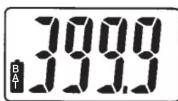
(1) Set the function selector switch to the "OFF" position.
(2) Unscrew and remove the battery compartment on the bottom of the instrument.
(3) Replace the batteries observing correct polarity. Use two new R03 or equivalent batteries.
(4) Mount and screw the battery compartment cover.


Factory: Ehime, Japan
www.kew-ltd.co.jp
- INSTRUCTION MANUAL AC/DC DIGITAL CLAMP METER KEWTECH KT203
- ⚠ WARNING
- NOTE
- Current Measurement
- WARNING
- △ DANGER
- CAUTION
- Voltage Measurement
- ⚠️ DANGER
- 6-1 AC Voltage Measurement
- 6-2 DC Voltage Measurement
- Resistance Measurement
- Other Functions
- 8-1 Sleep Function
- 8-2 Data Hold Function
- Preparation for Measurement
- Battery Replacement
- ⚠️ CAUTION
Brand : Kyoritsu
Model : KT 203
Category : Multimeter