
IM75-2 - Multimeter FLIR - Free user manual and instructions
Find the device manual for free IM75-2 FLIR in PDF.


| Type | Digital Multimeter with Thermal Imaging |
| Model | IM75-2 |
| Brand | FLIR |
| Dimensions | 215 x 102 x 56 mm |
| Weight | 0.55 kg (with batteries) |
| Power Supply | 4 x AA batteries (1.5V each) |
| Display | LCD with backlight, 4000 counts |
| AC Voltage Range | 0.1 mV to 1000 V |
| DC Voltage Range | 0.1 mV to 1000 V |
| AC Current Range | 0.1 mA to 10 A |
| DC Current Range | 0.1 mA to 10 A |
| Resistance Range | 0.1 Ω to 40 MΩ |
| Capacitance Range | 1 nF to 4 mF |
| Frequency Range | 0.001 Hz to 1 MHz |
| Temperature Measurement | -20°C to 1000°C (type K thermocouple) |
| Thermal Imaging Resolution | 160 x 120 pixels |
| Safety Rating | CAT III 600V, CAT IV 300V |
| True RMS | Yes |
| Data Logging | Yes, via Bluetooth to mobile app |
| Auto-ranging | Yes |
| Backlight | Yes, adjustable |
| Operating Temperature | 0°C to 50°C |
| Storage Temperature | -20°C to 60°C |
| Included Accessories | Test leads, type K thermocouple, USB cable, carrying case, batteries |
Frequently Asked Questions - IM75-2 FLIR
User questions about IM75-2 FLIR
0 question about this device. Answer the ones you know or ask your own.
Ask a new question about this device
Download the instructions for your Multimeter in PDF format for free! Find your manual IM75-2 - FLIR and take your electronic device back in hand. On this page are published all the documents necessary for the use of your device. IM75-2 by FLIR.
USER MANUAL IM75-2 FLIR
1.1 Copyright 4
1.2 Quality Assurance 4
1.3 Documentation 4
1.4 Disposal of Electronic Waste 4
2. SAFETY 5
2.1 FCC Compliance 6
2.2 Industry Canada Compliance 7
3. INTRODUCTION 8
3.1 Key Features 8
4. METER DESCRIPTION 9
4.1 Meter Sections 9
4.2 Function Switch Positions 10
4.3 Function Buttons, Selector Pad, and Rotary Switch 10
4.3.1 Selector Pad 11
4.3.2 Rotary Switch 11
4.4 Display Description 12
4.5 Display Icons and Indicators 13
5. OPERATION 14
5.1 Powering the Meter 14
5.1.1 Auto Power Off 14
5.2 Manual AC/DC Selection 14
5.3 Auto Range 14
5.4 'Smart' Out-of-Range Warnings 14
5.5 Data Hold and Auto-Hold Modes 14
5.5.1 Data Hold Mode 14
5.5.2 Auto-Hold mode 14
5.6 Voltage Measurements 15
5.7 Insulation Resistance Measurements 15
5.7.1 PI/DAR Test 15
5.8 Earth Bond Resistance Measurements (ZERO ) 16
5.9 Continuity Test 16
5.10 Diode Test 16
5.11 Capacitance Measurements 17
5.12 Extended Functionality 17
5.12.1 Selecting Modes 17
5.12.2 VFD Mode (ACV only) 18
5.12.3 Frequency Mode (ACV only) 18
5.12.4 Pass/Fail Mode (COMPARE) 18
5.12.5 Setup Utility 18
5.12.6 Silent Mode 19
5.12.7 Data Recording Mode (99-point) 19
5.13 Keypad Lockout 19
5.14 Streaming Measurement Data using METERLINK 20
5.14.1 General 20
5.14.2 Procedure 20
6. MAINTENANCE 21
6.1 Cleaning and Storage 21
6.2 Battery Replacement 21
6.3 Fuse Replacement 21
6.4 Disposal of Electronic Waste 21
7. SPECIFICATIONS 22
7.1 General specifications 22
7.2 Electrical Range Specifications 23
7.3 Input Specifications 25
8. CUSTOMER SUPPORT 26
9. WARRANTY 27
9.1 FLIR Limited Lifetime Warranty 27
1. Disclaimers
1.1 Copyright
© 2023, FLIR Systems, Inc. All rights reserved worldwide. No parts of the software including source code may be reproduced, transmitted, transcribed, or translated into any language or computer language in any form or by any means, electronic, magnetic, optical, manual, or otherwise, without the prior written permission of FLIR Systems.
The documentation must not, in whole or part, be copied, photocopied, reproduced, translated, or transmitted to any electronic medium or machine-readable form without prior consent, in writing, from FLIR Systems.
Names and marks appearing on the products herein are either registered trademarks or trademarks of FLIR Systems and/or its subsidiaries. All other trademarks, trade names or company names referenced herein are used for identification only and are the property of their respective owners.
1.2 Quality Assurance
The Quality Management System under which these products are developed and manufactured has been certified in accordance with the ISO 9001 standard.
FLIR Systems is committed to a policy of continuous development; therefore, we reserve the right to make changes and improvements on any of the products without prior notice.
1.3 Documentation
To access the latest manuals and notifications, go to the Download tab at: https://support.flir.com. It only takes a few minutes to register online. In the download area you will also find the latest releases of manuals for our other products, as well as manuals for our historical and obsolete products.
1.4 Disposal of Electronic Waste

As with most electronic products, this equipment must be disposed of in an environmentally friendly way, and in accordance with existing regulations for electronic waste.
Please contact your FLIR Systems representative for more details.
Safety Notes
- Before operating the device, you must read, understand, and follow all instructions, dangers, warnings, cautions, and notes.
- FLIR Systems reserves the right to discontinue models, parts or accessories, and other items, or to change specifications at any time without prior notice.
- Remove the batteries if the device is not used for an extended period.

Warning Statements
- Do not operate the device if you do not have the correct knowledge. Formal qualifications and/or national legislation for the electrical inspections can apply. Incorrect operation of the device can cause damage, shock, injury or death to persons.
- Do not start the measuring procedure before you have set the function switch to the correct position. This can cause damage to the instrument and can cause injury to persons.
- Do not change to resistance when you measure the voltage. This can cause damage to the instrument and can cause injury to persons.
- You must disconnect the test leads from the circuit that you did a test on before you change the range. If you do not do this, damage to the instrument and injury to persons can occur.
- Do not replace the batteries before you remove the test leads. This can cause damage to the instrument and can cause injury to persons.
- Do not use the device if the test leads and/or the device show signs of damage. Injury to persons can occur.
- Be careful when you do the measurements if the voltages are more than 25 VAC rms or 35 VDC. There is a risk of shock from these voltages. Injury to persons can occur.
- Do not do diode, resistance, or continuity tests before you have removed the power from capacitors and other devices under test during a measurement. Injury to persons can occur.
- Do not use the device as a tool to identify live terminals. You must use the correct tools. Injury to persons can occur if you do not use the correct tools.
- Make sure that children cannot touch the device. The device contains dangerous objects and small parts that children can swallow. If a child swallows an object or a part, speak with a physician immediately. Injury to persons can occur.
- Do not let children play with the batteries and/or the packing material. These can be dangerous for children if they use them as toys.
- Do not touch expired or damaged batteries without gloves. Injury to persons can occur.
- Do not cause a short-circuit of the batteries. This can cause damage to the instrument and can cause injury to persons.
- Do not put the batteries into a fire. Injury to persons can occur.
Cautions
Do not use the device for a procedure that it is not made for. This can cause damage to the protection.
 | This symbol, adjacent to another symbol or terminal, indicates that the user must refer to the manual for further information. |
 | This symbol, adjacent to a terminal, indicates that, under normal use, hazardous voltages may be present. |
 | Double insulation. |

UL listing is not an indication or a verification of the accuracy of the meter
2.1 FCC Compliance
This device complies with part 15 of the FCC Rules. Operation is subject to the following two conditions:
- This device may not cause harmful interference.
- This device must accept any interference received, including interference that may cause undesired operation.
This equipment has been tested and found to comply with the limits for a Class B digital device, pursuant to part 15 of the FCC Rules. These limits are designed to provide reasonable protection against harmful interference in a residential installation. This equipment generates, uses, and can radiate radio frequency energy and, if not installed and used in accordance with the instructions, may cause harmful interference to radio communications. However, there is no guarantee that interference will not occur in an installation. If this equipment does cause harmful interference to radio or television reception, which can be determined by turning the equipment off and on, the user is encouraged to try to correct the interference by one or more of the following measures:
- Reorient or relocate the receiving antenna.
- Increase the separation between the equipment and receiver.
- Connect the equipment into an outlet on a circuit different from that to which the receiver is connected.
- Consult the dealer or an experienced radio/TV technician for help.

WARNING
Changes or modifications not expressly approved by the party responsible for compliance could void the user's authority to operate the equipment.
2.2 Industry Canada Compliance
This device complies with part 15 of the FCC Rules. Operation is subject to the following two conditions:
This device complies with Industry Canada license-exempt RSS standard(s). Operation is subject to the following two conditions: (1) this device may not cause interference, and (2) this device must accept any interference, including interference that may cause undesired operation of the device.
3. Introduction
Thank you for selecting the FLIR IM75-2 Insulation Test / Digital MultiMeter. This device is shipped fully tested and calibrated and, with proper use, will provide years of reliable service.
3.1 Key Features
• 4000 count extra-large digital dual display with backlighting
• Auto Range with smart over-range indication
• Auto Hold and Standard Data Hold features
- On-screen menu selection and navigator key drive
• Variable-frequency drive mode (low-pass filter)
• Front panel insulation resistance test voltage selector
• COMPARE feature with front panel color coded PASS/FAIL LED indication
• 0.1% DCV accuracy
• 99-record data record/recall memory
• High power built-in work lights
• METERLINK® app compatibility
• Safety Category Rating: CAT IV-600V, CAT III-1000V
4. Meter Description
4.1 Meter Sections
- Courtesy Work lights
- LCD Display
- Pass-Fail (green/red) LED
- Rotary Function Switch
- Function Buttons (detailed below)
- Positive (+) probe input jack for Voltage, Capacitance, Diode, & Continuity
- COM (negative -) probe input jack
- Positive (+) probe input jack for insulation resistance and earth bond resistance
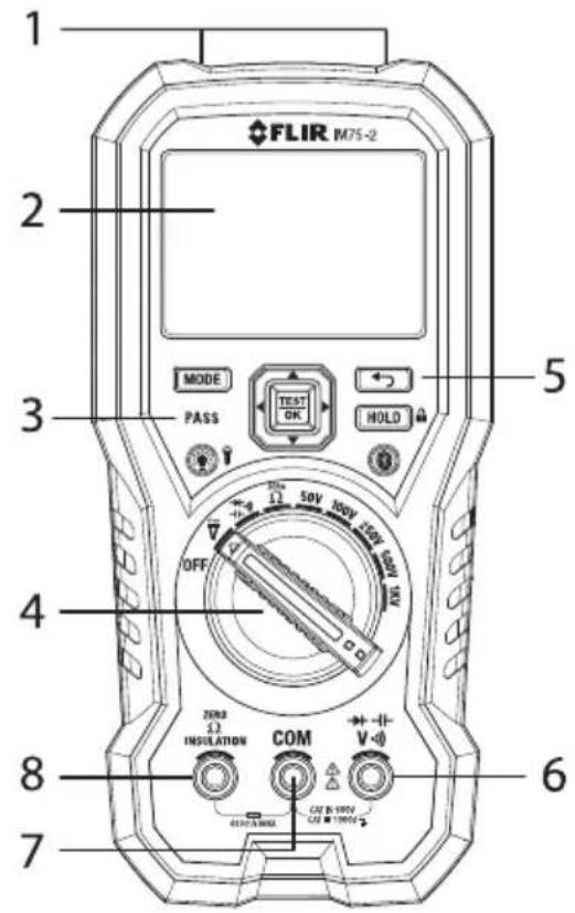
Fig 4-1 Front View
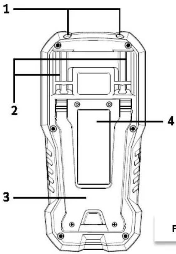
- Courtesy Work Lights
- Test Probe Holders
- Tilt Stand
- Battery and Fuse Access
Fig 4-2 Rear View
4.2 Function Switch Positions
| OFF | The meter is switched OFF and in full power-saving mode. |
| [66HK] | The meter can measure voltage (V) through the probe inputs. |
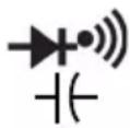 | The meter can measure capacitance, diode polarity or continuity through the probe inputs. The type of measurement is chosen by the MODE button. |
| ZERO Ω | Earth Bond Resistance testing mode. |
| 50V, 100V, 250V, 500V, 1KV: Insulation resistance test voltage selections | |
4.3 Function Buttons, Selector Pad, and Rotary Switch
 | Use this button to change the operating mode of the meter (ex: AC vs. DC)Also selects Insulation Resistance values to compare for PASS/FAIL testing |
 | Press to HOLD readings on the display during normal DMM measuring modes (see Section 5.5 Data Hold and Auto-Hold Modes). Press and hold for Keypad lockout mode (see Section 5.13 Keypad Lockout).In INSULATION TESTING MODE this button will serve to enable the test lock function for continuous insulation resistance testing. See Section 5.7 Insulation Resistance Measurements for further information. |
 | Use this Selector Pad to start/stop Insulation Resistance Tests, to enable extended functionality modes, and to navigate mode menu options. Further details provided in Section 4.3.1 Selector Pad |
 | The Rotary Switch is used to select a measurement function. Details are provided in Section 4.3.2 Rotary Switch |
 | Press this button to exit an extended functionality mode. |
 | Press this button to enable/disable the display backlight.Press and hold the button for 2 seconds to enable/disable the work light. |
 | Press to enable/disable METERLiNK communication, see section 5.14 Streaming measurement data using METERLiNK. |
4.3.1 Selector Pad
There are five (5) 'soft' function buttons arranged in a square, as shown below. The functions change depending on the sub-function chosen at the time. Generally, the arrow buttons are used for navigation and the TEST-OK button is used for selecting an object or starting a test. Detailed information below:

Fig 4-3 Selector Pad
Pressing the TEST OK button selects a menu-driven option. The TEST OK button is also used to enter the sub-menus for selection screens.
NOTE: When in INSULATION TESTING MODE pressing and holding TEST-OK outputs a test voltage (until the button is manually released). In Test Lock mode this button (used in conjunction with the HOLD/LOCK button) is used to Start and Stop continuous Insulation Resistance tests. See Section 5. Insulation Resistance Measurements for further details. Do not confuse the Insulation Resistance test lock feature with the Keypad Lockout feature (section 5.13).
The LEFT (⇐) button scrolls to previous choices in the current level of the menu. When reaching the start of a group of selections, further presses of the LEFT button wraps to the end of the list.
The RIGHT (→) button scrolls to next choices in the current level of the menu. When reaching the end of a group of selections, further presses of the RIGHT button wraps to the start of the list.
The UP ( ) button scrolls to previous selectable options in the current level of the menu.
When reaching the start of a group of selections, further presses of the UP button are ignored.
The DOWN (↓) button scrolls to previous selectable options in the current level of the menu.
When reaching the end of a group of selections, further presses of the DOWN button are ignored.
4.3.2 Rotary Switch
There are nine (9) dedicated Rotary Switch positions:

• OFF: The meter is switched OFF.
- AC/DC VOLTAGE: The meter can measure voltage through the probe inputs. The type of measurement (AC/DC) is chosen by the MODE button. The default measurement is AC voltage.
- CAPACITANCE/DIODE/CONTINUITY: The meter can measure capacitance, diode polarity or continuity through the probe inputs. The type of measurement is chosen by the MODE button.
- Zero : The meter can measure earth-bond resistance, through the probe inputs. The measurement unit is Ohms ( ).
- 50V: The meter can source a 50VDC TEST Voltage and measure Insulation Resistance through the Zero Ω/Insulation and COM probe inputs.
- 100V: The meter can source a 100VDC TEST Voltage and measure Insulation Resistance through the Zero /Insulation and COM probe inputs.
- 250V: The meter can source a 250VDC TEST Voltage and measure Insulation Resistance through the Zero /Insulation and COM probe inputs.
- 500V: The meter can source 500VDC TEST Voltage and measure Insulation Resistance through the Zero Ω/Insulation and COM probe inputs.
- 1000V: The meter can source 1000VDC TEST Voltage and measure Insulation Resistance through the Zero /Insulation and COM probe inputs.
4.4 Display Description
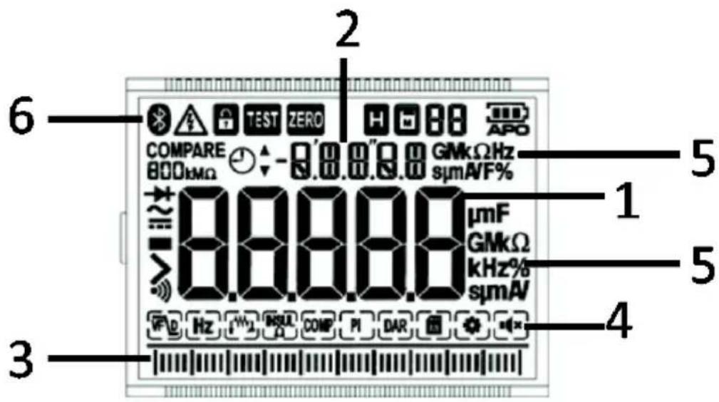
Fig 4-4 Display
- Main display area
- Secondary display area
- Bar graph (matches the reading on the main display)
- Modes of operation (detailed later in this guide)
- Units of measure for primary and secondary displays
- Alerts and status icons (detailed below)
4.5 Display Icons and Indicators
 | Indicates that Bluetooth communication is active |
| TEST | Indicates an Insulation Test in progress and test voltage is present |
 | Indicates that the measured voltage is greater than 30 V (AC or DC) |
| H | Indicates that the meter is in Hold mode (solid H) or auto hold (flashing H) |
 | Indicates that the meter is in locked mode |
| [26BX] | Memory icon shown with the active memory location (1-99) |
 | Indicates the battery voltage status |
| APO | Indicates that the auto power off function is enabled |
 | Indicates that the meter is measuring AC voltage |
 | Indicates that the meter is measuring DC voltage |
| Analog bar graph | |
 | VFD (variable frequency drive) mode icon |
 | Frequency mode icon |
 | Earth Bond Resistance icon |
| [STZZ] | Insulation Resistance icon |
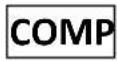 | Compare function icon |
 | Polarization Index icon |
 | Dielectric Absorption Ratio icon |
 | Settings mode icon |
 | Silent mode icon |
5. Operation
Note: Before operating the device, you must read, understand, and follow all instructions, dangers, warnings, cautions, and notes.
Note: When the meter is not in use, the function switch should be set to the OFF position.
Note: When connecting the probe leads to the device under test, connect the COM (negative) lead before connecting the positive lead. When removing the probe leads, remove the positive lead before removing the COM (negative) lead.
5.1 Powering the Meter
- Set the function switch to any position to switch on the meter.
- If the battery indicator 📄 shows that the battery voltage is low or if the meter does not power on, replace the battery. See section 6.2 Battery Replacement.
5.1.1 Auto Power Off
The meter enters sleep mode after 30 minutes of inactivity. The meter beeps three times 20 seconds before powering off. Press any button or turn the Rotary Switch to prevent the meter from powering off. The auto power off time-out is then reset. To disable auto power off (APO) press the MODE button while turning on the meter. To change the APO time, read section 5.12.6 Setup Utility
5.2 Manual AC/DC Selection
When measuring voltage, press the MODE button to select AC or DC voltage.
5.3 Auto Range
Auto-Range is the only mode of operation for Capacitance; ranges are automatically selected by the meter. Insulation Resistance tests allow for voltage test selection using the rotary switch.
5.4 'Smart' Out-of-Range Warnings
If the input is over/under the full-scale range, the display will show >x or <x, where x is the high or low end of the full-scale range.
5.5 Data Hold and Auto-Hold Modes
These two modes are discussed in detail below. In the Settings menu, if Auto-Hold is set to OFF, the meter will operate in the standard Hold mode. If Auto-Hold is set to ON in the settings menu, the meter will operate in the Auto-Hold mode.
5.5.1 Data Hold Mode
In Data Hold mode, press the HOLD button to capture the measurement that is shown on the main display. The captured reading will be displayed in the secondary, upper display area (the main display will then function normally). The 'H' display icon will appear solid on the LCD in the Hold mode. To exit the Hold mode, press the HOLD button again.
5.5.2 Auto-Hold mode
If Auto-Hold mode is switched ON in the settings menu, press the HOLD button to activate Auto-Hold mode (the 'H' display icon will appear flashing). In Auto-Hold mode readings are
captured in the say way as in standard Hold mode. The difference is that the captured reading, displayed on the smaller, secondary display digits, will update whenever a reading 50 digits higher or lower than the captured reading is measured. To exit the Auto-Hold mode press the HOLD button.
5.6 Voltage Measurements
- Set the function switch to the position.
- Insert the black probe lead into the COM terminal and red probe lead into the V terminal.
- Use the MODE button to select AC or DC voltage measurements.
- The indicator will be displayed for AC measurements.
- The indicator will be displayed for DC measurements.
- Connect the probe leads in parallel to the part under test
- Read the voltage value on the display
5.7 Insulation Resistance Measurements
- Use the rotary switch to select the insulation voltage (50V, 100V, 250V, 500V, or 1kV).
- Insert the black probe lead into the COM terminal and red probe lead into the Insulation terminal.
- Select INSUL to enable the Insulation Resistance Function mode as described in section 5.12.1 Selecting modes.
- During the Test, the insulation voltage will appear in the secondary (upper) reading area. The resistance will be shown in the main reading area.
- Press TEST OK to start test.
- To lock the test for continuous testing, press the HOLD/LOCK button (lock icon will appear) and then press TEST OK to test continuously.
- The TEST icon on the LCD will be shown while the voltage is outputted.
- Press TEST OK again to stop the test
NOTE: The 99-point Data Record memory function cannot be activated in the usual way while using the Insulation Resistance function (since the TEST OK button is used for testing in this case and not for saving readings). The last reading, however, is held on the display and can then be saved in the normal way as described in the Extended Functionality section below under Section 5.12.7 Data Record Mode.
5.7.1 PI/DAR Test
Note: PI (Polarization Index); DAR (Dielectric Absorption Ratio)
- Select the PI or DAR test as described in section 5.12.1 Selecting modes.
- Press the TEST OK button to test.
- Press the MODE button to show the test time at the upper reading area. (LCD will show CLOCK icon and the elapsed time). PI is a ten-minute test and DAR is a one-minute test.
- The test will stop automatically, and the result (ratio) will be shown on the main display area. The PASS/FAIL LED will indicate the test result (Green for PASS, and Red for FAIL).
5.8 Earth Bond Resistance Measurements (ZERO Ω)
- Move the function dial to the Earth-bond resistance position (ZERO ); the Earth-bond
resistance icon will appear.
- Insert the black probe lead into the COM terminal and red probe lead into the ZERO/Ohm/Insulation terminal.
- Before testing, short the ends of the probes and press the MODE button. The ZERO icon will appear on the display and the offset value will be stored. If the test leads are not shorted or if there is residual resistance, the display will show the >2.00 ohms (this indication could be due to faulty leads, improper test lead insertion, or meter problem. Tests should not be attempted until root cause of the high resistance is determined.
- Connect the test leads to the Device under test.
- Press TEST OK to run a test.
- To lock the test ON, press the HOLD/LOCK button (the LOCK icon will appear) and then press TEST OK to test continuously.
- Press TEST OK again to stop the test.
- Note that the Earth Bond Resistance Measurement mode can also be used to measure standard resistance to 40kohms
NOTE: The 99-point Data Record memory function cannot be activated in the usual way while using the Earth Bond Resistance function (since the TEST OK button is used for testing in this case and not for saving readings). The last reading, however, is held on the display and can then be saved as described in the Extended Functionality section below under Section 5.12.7 Data Recording Mode.
5.9 Continuity Test
Warning: Do not do diode, resistance or continuity tests before removing the power from capacitors and other devices under test during a measurement. Injury to persons can occur.
- Set the function switch to the ● position.
- Insert the black probe lead into the COM terminal and red probe lead into the V terminal.
- Use the MODE button to select continuity measurement. The ●) indicator will be displayed.
- Insert the black probe lead into the COM (negative) terminal and the red probe lead into the positive terminal.
- Touch the tips of the probe across the circuit or component under test.
- If the resistance is 30 ± 5 (nominal) or less, the meter will beep.
Note: This threshold is user selectable in the SET UP menu under the Cntin (continuity) setting: Range: 10-50 Ω; Increment: 1; Default: 30 Ω.
5.10 Diode Test
Warning: Do not do diode, resistance, or continuity tests before you have removed the power from capacitors and other devices under test during a measurement. Injury to persons can occur.
-
Set the function switch to the position.
-
Use the MODE button to select the diode test function. The ➤ indicator will be displayed.
- Insert the black probe lead into the COM (negative) terminal and the red probe lead into the positive V terminal.
- Touch the tips of the probes across the diode or semiconductor junction under test. Make a note of the value on the display.
- Reverse the polarity of the probes, by interchanging the probe test locations.
- Touch the tips of the probe across the diode or semiconductor junction under test. Make a note of the new value on the display.
- The diode or semiconductor junction can be evaluated as follows:
If one of the readings displays a value (Typically 0.4.00 to 0.900 V) and the other reading displays a value (-0.400 to -0.900 V), the component is good.
If both readings display OL, the component is either open or shorted.
Use Continuity mode to determine if it is open or shorted.
5.11 Capacitance Measurements
Warning: Do not do capacitance tests before removing the power to the capacitor or other devices under test during a measurement. Injury to persons can occur.
- Set the function switch to the -position.
- Use the MODE button to select the capacitance measurement. The F (Farad) unit will be displayed.
- Insert the black probe lead into the COM (negative) terminal and the red probe lead into the positive terminal.
- Touch the tips of the probe across the part under test.
- Read the capacitance value on the display.
Note: For very large capacitance values, it may take several seconds for the measurement to settle and the final reading to stabilize.
5.12 Extended Functionality
A variety of modes are available that provide extended functionality as detailed below.
5.12.1 Selecting Modes
The mode icons applicable for the selected measurement type are displayed in the lower part of the display. When a mode is enabled, the icon is framed.

Fig 5-1 Mode Icons
Use the left/right arrow buttons to navigate to the desired mode icon. The currently selected icon will flash.
-
Press the TEST OK button to enable the selected (flashing) mode.
-
Use the up/down arrow buttons to step through the mode options (if any). Refer to the section related to the specific mode for detailed instructions.
- Press the TEST OK button to disable the selected (flashing) mode.
5.12.2 VFD Mode (ACV only)
In VFD (variable-frequency drive) mode, high-frequency noise is eliminated from the voltage measurement using a low-pass filter. VFD mode is available when measuring ACV.
- Select and then press the TEST OK button to enable the selected (flashing) mode.
5.12.3 Frequency Mode (ACV only)
In Frequency mode, the frequency is displayed in the main display and the period is displayed in the secondary display. Frequency mode is available when measuring AC voltage.
- Select Hz and enable Frequency mode as described in section 5.12.1, Selecting modes.
5.12.4 Pass/Fail Mode (COMPARE)
- Select the desired insulation voltage value using the rotary switch.
- Select COMP and enable the Pass/Fail Function mode as described in section 5.12.1 Selecting modes.
- Use the MODE button to select the resistance value to compare. Resistance value segments and a COMPARE icon are shown on the LCD. See the test voltages and corresponding resistance value options in the table below.
- Press TEST to start the process.
- Observe the green light / red light for PASS / FAIL indication.
| Test Voltages (V) | Resistance Options (kΩ) | Resistance Options (MΩ) |
| 50 | 100 /200 /500 | 1/2/5/10/20/50 |
| 100 | 1/2/5/10/20/50/100 | |
| 250 | 1/2/5/10/20/50/100/200 | |
| 500 | 1/2/5/10/20/50/100/200/500 | |
| 1000 | 1/2/5/10/20/50/100/200/500 |
5.12.5 Setup Utility
In Setup, define the settings for various meter options:
- Auto power off (indicated by the text APO): A mode where the time period after which the meter enters sleep mode can be set. The range is 1 to 30 minutes, or OFF. The factory default is 10 minutes.
- Auto backlight off (indicated by the text b.Lit): A mode where the time period after which the backlight turns off can be set. The range is 1 to 30 minutes, or OFF. The factory default is 5 minutes.
- Continuity threshold (indicated by the text Cntin): A mode where the threshold for continuity tests can be set.
-
Auto hold (indicated by the text A.Hold): Select Auto hold mode ON (Auto hold mode active) or OFF (Data hold mode active). For more information, see section 5.5 Data hold mode and Auto hold mode.
-
Select ⚙️ and enable Setup mode as described in section 5.12.1 Selecting modes.
- Use the up/down arrows button to cycle through the mode options APO, b.Lit, Cntin, A.Hold, and RESET shown on the secondary display.
-
Press the TEST OK button to activate the displayed option.
-
APO: Use the left/right arrow buttons to change the auto power off time.
- b.Lit: Use the left/right arrow buttons to change the auto backlight off time.
- A.Hold: Use the left/right arrow buttons to configure auto hold/data hold. On indicates that the auto hold mode is active. Off indicates that the data hold mode is active.
- Cntin: Use the left/right arrow buttons to change the continuity threshold.
- RESET: Press the TEST OK button to reset the settings to the factory default.
5.12.6 Silent Mode
In Silent mode, the alert beeper is disabled. Silent mode does not affect the continuity beeper.
Select and enable Silent mode as described in section 5.12.1 Selecting modes.
5.12.7 Data Recording Mode (99-point)
The meter has 99 memory locations for the storage of measurement data.
Select and enable MEM mode as described in section 5.12.1 Selecting modes.
Use the arrow keys to cycle through the mode options: SAVE, LOAD, and CLEAR shown on the secondary display.
SAVE: The data on the main display is saved to a memory location indicated by the '88' in the upper display area.
LOAD: The data stored in the memory location (identified by the '88' indicator) is displayed.
Use arrow keys to scroll the memory locations. Use the button to exit the LOAD mode.
CLEAR: The data in all memory locations is erased.
5.13 Keypad Lockout
In Lockout mode the meter ignores all button presses except HOLD. The auto power off function, see section 5.1.1 Auto Power off, is disabled in Lockout mode.
Press and hold the HOLD/LOCK button for 3 seconds to enter/exit the lockout mode. In lockout mode, the lock indicator is displayed. Do not confuse Lockout mode with the test lock feature used for continuous Insulation Resistance testing (see Section 5.7 Insulation Resistance Measurements).
5.14 Streaming Measurement Data using METERLINK
5.14.1 General
You can stream measurement data to a mobile device using the METERLINK app. The app is available from the Apple Store ^® (iOS) or from Google Play ^™ (Android).
5.14.2 Procedure
- Download the METERLINK app to your mobile device and open the app.
- Power the meter and select the desired measurement mode.
- Press the meter's Bluetooth button ✪ to enable communications.
- Follow the instructions and prompts on the METERLINK app screens.
6.1 Cleaning and Storage
Clean the meter with a damp cloth and mild detergent; do not use abrasives or solvents.
If the meter is not to be used for an extended period, remove the batteries and store them separately.
6.2 Battery Replacement
The Battery symbol flashes with no 'bars' when the batteries have reached a critical level of 7.0V. The symbol stays active and visible while the LCD is powered.
The meter displays readings within specifications while the low battery indicator is on. When this is no longer possible, the display must be blanked. The meter powers off before it displays an out of tolerance voltage.
- To avoid electrical shock, disconnect the meter if connected to a circuit, remove the probe from the terminals, and set the function switch to the OFF position before attempting to replace the batteries.
- Unscrew and remove the battery compartment cover.
- Replace the six standard AAA batteries, observing correct polarity.
- Secure the battery compartment cover.

Never dispose of used batteries or rechargeable batteries in household waste. As consumers, users are legally required to take used batteries to appropriate collection sites, the retail store where the batteries were purchased, or wherever batteries are sold.
6.3 Fuse Replacement
The fuse accessed via the battery compartment cover. The fuse is rated 440mA/1000V, ceramic fast blow with a minimum Interrupt Rating of 10kA.
6.4 Disposal of Electronic Waste

As with most electronic products, this equipment must be disposed of in an environmentally friendly way, and in accordance with existing regulations for electronic waste. Please contact your FLIR Systems representative for more details.
7. Specifications
7.1 General specifications
| Display | 4,000-count with bar graph |
| Controls | 9-position rotary switch |
| 4-way Selector Pad with center OK/TEST button | |
| LED: Pass (Green), Fail (Red) | |
| (5) dedicated function buttons: Mode, Cancel, Hold/Lock, Bluetooth, Backlight | |
| Backlight White LED | |
| Work Lights White LED array | |
| Measurement Rate 2 samples per second, nominal | |
| Display Rate 2 times per second | |
| Input Impedance | 10MΩ VDC/VAC < 100pF |
| AC Voltage Bandwidth 50Hz to 500Hz | |
| Power Supply 6 x 'AAA' (LR03) batteries | |
| Battery Life Considerations | The meter can perform 1200 Earth-Bond resistance measurements with new alkaline batteries. These are standard tests of 1Ω with a duty cycle of 5 seconds ON and 25 seconds OFF.Insulation Resistance: The meter can perform 300 Insulation Resistance tests with new alkaline batteries. These are standard tests of 1MΩ with a duty cycle of 5 seconds ON and 25 seconds OFF. This does not include Bluetooth or Backlight use. |
| Auto Power Off (APO) | User programmable OFF to 30 minutes in 1-minute increments, with audible pre-alert (20 seconds) |
| Measurement Types | True RMS AC Volts, DC Volts, Earth Bond Resistance, Insulation Resistance, Capacitance, Diode, and Continuity |
| Over-current Protection (fuse) | 440mA/1000V, ceramic fast blow fuse with a minimum Interrupt Rating of 10kA |
| Polarization Index and Dielectric Absorption Ratio Tests | PI (Polarization Index) = R10-min/R1-minDAR (Dielectric Absorption Rations) = R1-min/R30-secWhere R10-min: The insulation resistance measured at the 10-minute point after pressing the TEST button.R1-min: The insulation resistance measured at the 1-minute point after pressing the TEST button.R30-sec: The insulation resistance measured at the 30 second point after pressing the TEST button. |
| Other Indications | Progressive Low Battery, Over Range |
| Internal Memory (99) storage locations | |
| Operating Temperature | 32 to 122°F (0 to 50°C) |
| Storage Temperature | -4 to 140°F (-20 to 60°C) |
| Operating Humidity | Max 80% up to 95°F (35°C) decreasing linearly to 60% at 113°F (45°C) |
| Storage Humidity 80% maximum | |
| Indoor use only | |
| Altitude 6561 ft. (2000 m) | |
| Dimensions | 2.4 x 3.9 x 8.2 in. (60.7 x 98.1 x 207.1 mm) |
| Weight | 1.33 lbs. (605 g), including batteries |
| Agency Approvals | FCC Class B, CE, UL, RCM, UKCA |
| IP Rating IP54 | |
| Drop test rating 9.8 ft. (3 m) | |
7.2 Electrical Range Specifications
Note: Accuracy is stated at 65°F to 83°F (18°C to 28°C) and less than 75% RH)
| Function | Range | Resolution | Accuracy of Reading |
| DC Voltage | 1000.0V | 0.1V | ± (0.1% + 5 digits) |
| AC Voltage | 1000.0V | 0.1V | 50Hz to 60Hz ± (1.5% +5 digits);61Hz to 500Hz ± (2.0% + 5 digits) |
| VFD AC Voltage | 1000.0V | 0.1V | 50 to 60Hz ± (1.5% +5 digits);61 to 400Hz ± (5.0% + 5 digits) |
Notes: 1. Measurement start-voltage: <50V for VAC (add 20 digits for accuracy)
2. VFD/LPF Cutoff: 800Hz (-3dB point)
3. Input Impedance 10MΩ (less than 100pF)
| Function | Range | Resolution | Accuracy of Reading | |
| Earth-Bond Resistance | 40.00 Ω | 0.01Ω | ± (1.5% + 5 digits) * | |
| 400.0 Ω | 4000Ω | 0.1Ω | ± (1.5% + 3 digits) | |
| 40.00kΩ | 1Ω | |||
| 0.01KΩ |
Notes: 1. * ≤ 1.00Ω add 3 digits.
2. Open Circuit Test Voltage: >4.0V, <8V
3. Short Circuit Current ≥ 200.0mA
4. Live Circuit Detection if Greater than or equal to 2V @AC/DC Inputs test inhibited.
The top LCD will display the actual live voltage sensed.
| Function | Range | Resolution | Accuracy of Reading |
| Continuity | 400.0Ω | 0.1 Ω | ± (0.5% + 2 digits) |
| Diode | 2.000V | 0.001V | ± (1.5% + 2 digits) |
Notes:
Continuity: Built-in buzzer sounds when measured resistance threshold is met (adjustable from 10Ω to 50Ω, default is 30Ω).
Continuity MAX Test Current: 1mA
Continuity MAX Open Circuit Voltage >3.0V
Diode MAX Test Current: 1mA
Diode MAX Open Circuit Voltage: 3.0V
Overload Protection: 1000V AC rms or DC
| Function | Range | Resolution | Accuracy of Reading |
| Capacitance | 1000 μF | 1μF | ± (1.2% + 2 digits) |
| 10.00mF | 0.01mF | ± (1.2% + 20 digits) |
Notes: 1. Overload Protection: 1000V AC rms or DC
| Function | Range | Resolution | Accuracy of Reading |
| Frequency (ACV) | 400.0Hz 0.1Hz | ±5 digits | |
| 4.000kHz | 0.001kHz | ±5 digits | |
| 40.00kHz | 0.01kHz | ±5 digits |
| Function Resistance | Range | Resolution | Accuracy of Reading |
| Insulation Resistance | 4.000MΩ | 0.001MΩ | ± (1.5% + 5 digits) |
| 40.00 MΩ | 0.01MΩ | ||
| 400.0MΩ | 0.1MΩ | ± (3.0% + 5 digits) | |
| 4000 MΩ | 1MΩ | ||
| 4.1GΩ to 20.0GΩ | 0.1GΩ | ± (10.0% + 3 digits) | |
| Test voltages | Min. Resistance | Max. Resistance | |
| 50V | 50kΩ | 50.0MΩ | |
| 100V | 100kΩ | 100.0MΩ | |
| 250V | 250kΩ | 250.0MΩ | |
| 500V | 500kΩ | 500.0MΩ | |
| 1000V | 1MΩ | 20GΩ |
Notes: 1. Test Current = 1 mA
2. Test Voltage Accuracy: +0% to +20%; Short Circuit Test Current: 1mA (nominal)
3. Auto Discharge Function: Discharge time <1 second for Cap. <1μF
4. Max. Capacitive Load: Operable with up to 1 F load.
5. Live Circuit Detection: If >2V AC/DC detected test inhibited.
The top LCD will display the actual live voltage sensed.
7.3 Input Specifications
| Function | Maximum Input |
| AC Voltage, DC Voltage | 1000V DC/AC |
| Insulation Test | No LIVE Voltage IN - Protected |
8. Customer Support
For technical assistance, repair and returns, document downloads, and general information, visit the support site, link below:
https://support.flir.com
9. Warranty
9.1 FLIR Limited Lifetime Warranty
This product is protected by FLIR's Limited Lifetime Warranty.
Visit https://support.flir.com/prodreg to register your product and read the Limited Lifetime Warranty document.
Website
https://www.flir.com
Customer Support
https://support.flir.com
Disclaimer
Specifications subject to change without further notice. Models and accessories subject to regional market considerations. License procedures may apply. Products described herein may be subject to US Export Regulations. Please refer to exportquestions@flir.com with any questions.
There is no export-controlled information contained in this user manual.
Publication Identification No.:
IM75-2_en-US
Release version: AA
Release Date: 2023 September
Language: en-US
Copyright © 2023, Teledyne FLIR Commercial Systems, Inc.
All rights reserved worldwide.


- SAFETY 5
- INTRODUCTION 8
- METER DESCRIPTION 9
- OPERATION 14
- MAINTENANCE 21
- SPECIFICATIONS 22
- CUSTOMER SUPPORT 26
- WARRANTY 27
- Disclaimers
- Copyright
- Quality Assurance
- Documentation
- Disposal of Electronic Waste
- Safety Notes
- Warning Statements
- Cautions
- FCC Compliance
- WARNING
- Industry Canada Compliance
- Introduction
- Key Features
- Meter Description
- Meter Sections
- Function Switch Positions
- Function Buttons, Selector Pad, and Rotary Switch
- Selector Pad
- Rotary Switch
- Display Description
- Display Icons and Indicators
- Operation
- Powering the Meter
- Auto Power Off
- Manual AC/DC Selection
- Auto Range
- 'Smart' Out-of-Range Warnings
- Data Hold and Auto-Hold Modes
- Data Hold Mode
- Auto-Hold mode
- Voltage Measurements
- Insulation Resistance Measurements
- PI/DAR Test
- Earth Bond Resistance Measurements (ZERO Ω)
- Continuity Test
- Diode Test
- Capacitance Measurements
- Extended Functionality
- Selecting Modes
- VFD Mode (ACV only)
- Frequency Mode (ACV only)
- Pass/Fail Mode (COMPARE)
- Setup Utility
- Silent Mode
- Data Recording Mode (99-point)
- Keypad Lockout
- Streaming Measurement Data using METERLINK
- General
- Procedure
- Cleaning and Storage
- Battery Replacement
- Fuse Replacement
- Disposal of Electronic Waste
- Specifications
- Electrical Range Specifications
- Input Specifications
- Customer Support
- Warranty
- FLIR Limited Lifetime Warranty
- Disclaimer
Brand : FLIR
Model : IM75-2
Category : Multimeter