
DM93-2 - Multimeter FLIR - Free user manual and instructions
Find the device manual for free DM93-2 FLIR in PDF.


| Product Type | Digital Multimeter |
| Brand | FLIR |
| Model | DM93-2 |
| Display Counts | 6000 |
| True RMS | Yes |
| AC Voltage Range | 600V (True RMS) |
| DC Voltage Range | 600V |
| AC Current Range | 10A |
| DC Current Range | 10A |
| Resistance Range | 60MΩ |
| Capacitance Range | 60mF |
| Frequency Range | 10MHz |
| Temperature Measurement | -20°C to 1000°C (with thermocouple) |
| Diode Test | Yes |
| Continuity Test | Yes |
| Safety Rating | CAT IV 600V, CAT III 1000V |
| Power Supply | 9V battery (NEDA 1604, 6LR61) |
| Dimensions (H x W x D) | 200 mm x 95 mm x 50 mm |
| Weight | 400 g (with battery) |
| Display Backlight | Yes |
| Auto Ranging | Yes |
| Data Hold | Yes |
| Relative Mode | Yes |
| Min/Max Recording | Yes |
Frequently Asked Questions - DM93-2 FLIR
User questions about DM93-2 FLIR
0 question about this device. Answer the ones you know or ask your own.
Ask a new question about this device
Download the instructions for your Multimeter in PDF format for free! Find your manual DM93-2 - FLIR and take your electronic device back in hand. On this page are published all the documents necessary for the use of your device. DM93-2 by FLIR.
USER MANUAL DM93-2 FLIR
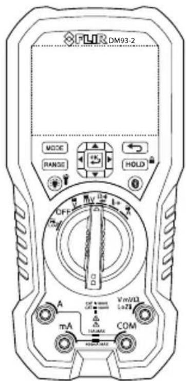
User's manual FLIR DM93-2
True RMS Industrial Multimeter
1 Disclaimers. . . . . . . . . . . . . . . . . . . . . . . . . . . . . . . . . . . . . . . . . .
1.1 Copyright.
1.2 Quality assurance ....
1.3 Documentation updates ....
1.4 Disposal of electronic waste.
2 Safety information....2
2.1 FCC Compliance ....
2.2 Industry Canada compliance.
3 Introduction 7
3.1 Key features.....
4 Description 8
4.1 Meter description .....
4.2 Function switch . . . . . . . . . . . . . . . . . . . . . . . . . . .
4.3 Function buttons ....
4.4 Display description .....
4.5 Display icons and indicators ....
4.5.1 Probe indicator ....
4.5.2 Out-of-range warning ....
5 Operation....14
5.1 Powering the meter .....
5.1.1 Auto power off. ....
5.2 Auto/Manual select mode .....
5.3 Auto/Manual Range mode .....
5.4 Voltage measurements .....
5.5 Resistance measurements .....
5.6 Continuity test.
5.7 Diode testing.
5.8 Capacitance measurements .....
5.9 Type K temperature measurements. . . . . . . . . . . . . . . . . .
5.10 Current measurements .....
5.11 Extended functionality .....
5.11.1 Selecting the mode .....
5.11.2 VFD mode (ACV and ACA only) .....
5.11.3 Peak mode (ACV and ACA only) ....
5.11.4 Min/Max/Avg mode . . . ........ . . . . . . . . .
5.11.5 Frequency mode (ACV and ACA only) . . . . . . . . .
5.11.6 Relative mode . . . . . . . . . . . . . . . . . . . . .
5.11.7 dBm mode (ACV only) . . . . . . . . . . . . . . . .
5.11.8 Manual Data Recording mode. . . . . . . . . . . . .
5.11.9 Automatic Data Recording mode. . . . . . . . . . . . .
5.11.10 Setup mode .....
5.11.11 Silent mode .....
5.12 Normal hold mode and Auto hold mode . . . . . . . . . . . . .
5.12.1 Normal hold mode .....
5.12.2 Auto hold mode .....
5.13 Locked mode .....
5.14 Streaming measurement data using
METERLINK ....
5.14.1 General.
5.14.2 Procedure . . . . . . . . . . . . . . . . . . . . . . . . .
6 Maintenance....28
6.1 Cleaning and storage.
6.2 Battery replacement .....
6.3 Fuse replacement .....
6.4 Disposal of electronic waste.....
7 Technical specifications .....
7.1 General specifications.
7.2 Electrical specifications .....
8 Technical support for external meters .....
9 Warranty 39
1.1 Copyright
To access the latest manuals, translations of manuals, and notifications, go to the Download tab at:
© 2023 FLIR Systems, Inc. All rights reserved worldwide.
No parts of the software including source code may be re- http://support.flir.com
produced, transmitted, transcribed or translated into any In the download area you will also find the latest releases language or computer language in any form or by any of manuals for our other products, as well as manuals for means, electronic, magnetic, optical, manual or otherwise our historical and obsolete products.
without the prior written permission of FLIR Systems.
The documentation must not, in whole or part, be copied
photocopied, reproduced, translated or transmitted to any electronic medium or machine readable form without prior consent, in writing, from FLIR Systems.
Names and marks appearing on the products herein are either registered trademarks or trademarks of FLIR Systems and/or its subsidiaries. All other trademarks, trade
names or company names referenced herein are used for identification only and are the property of their respective owners.
1.2 Quality assurance
The Quality Management System under which these products are developed and manufactured has been fied in accordance with the ISO 9001 standard.
FLIR Systems is committed to a policy of continuous development; therefore we reserve the right to make changes and improvements on any of the products with out prior notice.
ed, 1.4 Disposal of electronic waste
Electrical and electronic equipment (EEE) contains materials, components and substances that may be hazardous and present a risk to human health and the environment when waste electrical and electronic equipment (WEEE) is not handled correctly.
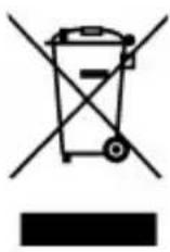
Equipment marked with the below crossed-out wheeled bin is electrical and electronic equipment. The crossed-out wheeled bin symbol indicates that waste electrical and electronic equipment should not be discarded together with unseparated household waste, but must be collected separately.
For this purpose all local authorities have established collection schemes under which residents can dispose waste electrical and electronic equipment at a recycling centre
or other collection points, or WEEE will be collected directly from households. More detailed information is available from the technical administration of the relevant local authority.
1.3 Documentation updates
Our manuals are updated several times per year, and also issue product-critical notifications of changes on a regular basis.
2 Safety information
Note Before operating the device, you must read, understand, and follow all instructions, dangers, warnings, cautions, and notes.
Note FLIR Systems reserves the right to discontinue models, parts or accessories, and other items, or to change specifications at any time without prior notice.
 NOTE NOTE | |
| Remove the batteries if the device is not used for an extended period of time | |
 WARNING WARNING | |
| Do not operate the device if you do not have the correct knowledge. Formal qualifications and/or national legislation for the electrical inspections can apply. Incorrect operation of the device can cause damage, shock, injury or death to persons. | |
 WARNING WARNING | |
| Do not start the measuring procedure before you have set the function switch to the correct position. This can cause damage to the instrument and can cause injury to persons. | |
 WARNING WARNING | |
| Do not change to current or resistance when you measure the voltage. This can cause damage to the instrument and can cause injury to persons. | |
 WARNING WARNING | |
| Do not apply more than 1000 V between the terminals or between a terminal and the earth ground. This can cause damage to the instrument and injury to persons. | |
| WARNING | |
| You must disconnect the test leads from the circuit that you did a test on before you change the range. If you do not do this, damage to the instrument and injury to persons can occur. | |
| WARNING | |
| Do not replace the batteries or the fuses before you remove the test leads. This can cause damage to the instrument and can cause injury to persons. | |
| WARNING | |
| Do not use the device if the test leads and/or the device show signs of damage. Injury to persons can occur. | |
| WARNING | |
| To prevent injury from an electric shock, do not connect or disconnect the probes or the test leads while they are connected to a voltage source. Keep your fingers behind the finger guards on the test leads. Be careful when you measure voltages that are more than 25 VAC rms, 42 VAC peak, or 35 VDC. There is a risk of electrical shock at these voltage levels. Injury to persons can occur. | |
| WARNING | |
| Disconnect the circuit power and remove the electrical power from all capacitors and/or inductive devices before you do a test of these:The resistanceThe continuityThe diodesThe capacitance.Damage to the equipment and injury to persons can occur. | |
| Only use this equipment indoors. This instrument is not for permanent outdoor installations. Damage to the equipment can occur if you use it outdoors. | |
| WARNING | |
| Do not apply a voltage to the unit when:It is not in the specified rangeThe switch position is not correctThe input value is not correct.Damage to the equipment can occur. | |
| WARNING | |
| Always make sure that the protective rating of a function is not more than the specified value. Damage to the equipment can occur. | |
| WARNING | |
| Be careful when you do voltage checks on the electrical outlets. These checks are not easy to do because you cannot be sure of the connection to the recessed electrical contacts. You must not only use this device to make sure that the terminals are not “live”. There is a risk of electrical shock. Injury to person can occur. | |
| CAUTION | |
| Do not use the device for a procedure that it is not made for. This can cause damage to the protection. |
 | This symbol, adjacent to another symbol or terminal, indicates that the user must refer to the manual for further information. |
 | This symbol, adjacent to a terminal, indicates that, under normal use, hazardous voltages may be present. |
 | Double insulation. |

LISTED
meter
2.1 FCC Compliance
This device complies with part 15 of the FCC Rules. Operation is subject to the following two conditions:
- This device may not cause harmful interference.
- This device must accept any interference received, including interference that may cause undesired operation.
This equipment has been tested and found to comply with the limits for a Class digital device, pursuant to part 15 of the FCC Rules. These limits are designed to provide reasonable protection against harmful interference in a residential installation. This equipment generates, uses, and can radiate radio frequency energy and, if not installed and used in accordance with the instructions, may cause harmful interference to radio communications. However, there is no guarantee that interference will not occur in a particular installation. If this equipment does cause harmful interference to radio or television reception, which can be determined by turning the equipment off and on, the user is encouraged to try to correct the interference by one or more of the following measures:
- Reorient or relocate the receiving antenna.
- Increase the separation between the equipment and receiver.
- Connect the equipment into an outlet on a circuit different from that to which the receiver is connected.
- Consult the dealer or an experienced radio/TV technician for help.
| CAUTION |
| Exposure to Radio Frequency Radiation.To comply with FCC/IC RF exposure compliance requirements, a separation distance of at least 20 cm must be maintained between the antenna of this device and all persons. This device must not be co-located or operating in conjunction with any other antenna or transmitter. |
| WARNING |
| Changes or modifications not expressly approved by the party respons compliance could void the user's authority to operate the equipment. |
2.2 Industry Canada compliance
This device complies with Industry Canada licence-exempt RSS standard(s). Operation is subject to the following two conditions: (1) this device may not cause terference, and (2) this devicemust accept any interference, including interference that may cause undesired operation of the device.
| CAUTION |
| Exposure to Radio Frequency Radiation.To comply with RSS 102 RF exposure compliance requirements, for n configurations, a separation distance of at least 20 cm must be maint tween the antenna of this device and all persons. This device must r located or operating in conjunction with any other antenna or transmitt |
3 Introduction
Thank you for choosing a FLIR DM93-2 digital multimeter.
This device is shipped fully tested and calibrated and, with proper use, will provide years of reliable service.
3.1 Key features
• 4000/40 000 counts extra-large digital dual display.
- Auto selection AC/DC in voltage and current modes.
- On-screen menu selection and navigator key drive.
- Variable-frequency drive mode (low-pass filter).
• 0.05% DCV accuracy.
- Low-Z measurement.
- Auto hold.
- Peak hold measurement.
• dB/dBm measurement.
• 10,000-record automatic data recording capacity.
- 99-record manual data record/recall memory.
• 3 m drop tested and IP54 rated.
- Dual display shows two measurements simultaneously.
- Share measurement data with mobile devices using the iOS® and Android™ METERLINK® app.
- Safety category rating: CAT IV-600V, CAT III-1000V.
4 Description
4.1 Meter description
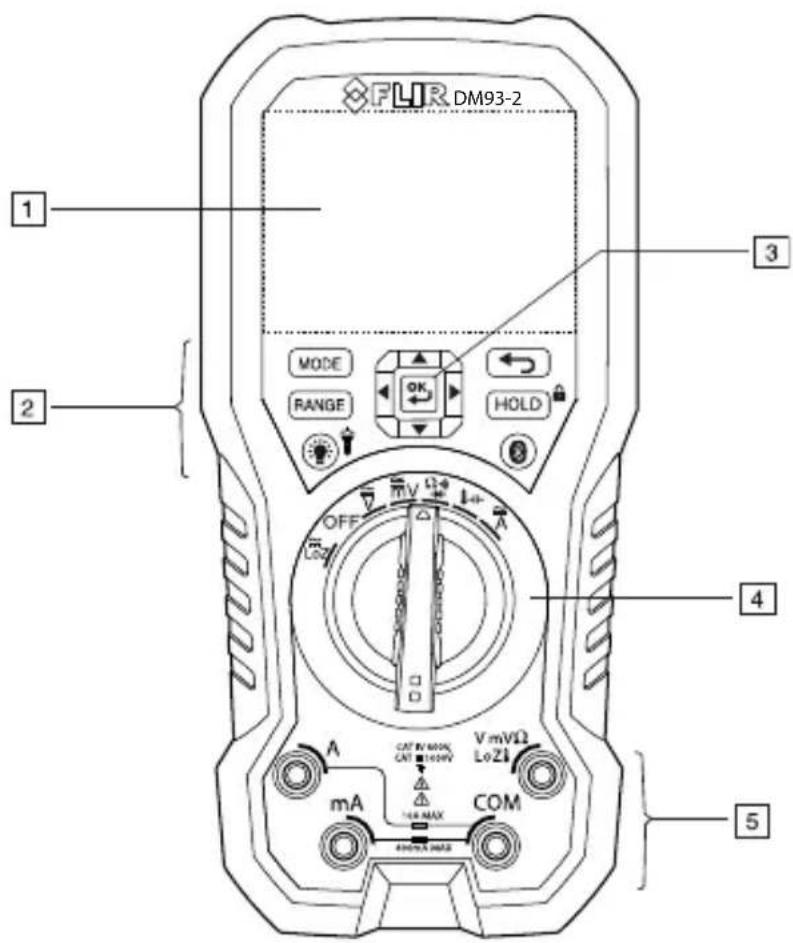
Figure 4.1 Front view
- LCD display.
- Function buttons, see section 4.3 Function buttons, page 10.
- Selector pad.
- Function switch, see section 4.2 Function switch, page 9.
- Probe input terminals.
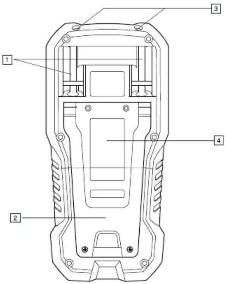
Figure 4.2 Rear view
- Probe clips.
- Tilt stand.
- Work light.
- Battery compartment cover.
4.2 Function switch
| LoZ | The meter can measure voltage through the probe inputs. A impedance load is placed across the inputs to stabilize the measurement. |
| OFF | The meter is in full power-saving mode. |
| The meter can measure high voltage (V) through the probe | |
| The meter can measure low voltage (mV) through the probe inputs. |
low-
inputs.
 | The meter can measure resistance, continuity, or diode polarity through the probe inputs. The type of measurement is selected by theMODEbutton. |
 | The meter can measure capacitance through the probe inputs or temperature through a thermocouple adapter. The type of measurement is selected by theMODEbutton. |
 | The meter can measure current through the probe inputs. |
4.3 Function buttons
 | ·Use the button to select Auto select or Manual select mode, see section 5.2 Auto/Manual select mode, page 14.·In Manual select mode, press the button to change the operating mode. |
 | ·Use the button to select Auto range or Manual range mode, see section 5.3 Auto/Manual Range mode, page 15.·In Manual range mode, press the button to change the range (scale). |
 | ·Press the button to toggle between Normal and Hold mode, see section 5.12 Normal hold mode and Auto hold mode, page 25.·Press and hold the button for 5 seconds to enable/disable Locked mode, see section 5.13 Locked mode, page 26. |
 | Use the selector pad to enable extended functionality modes and to navigate in mode options. |
 | Press the button to exit an extended functionality mode. |
4 Description
 | Press the button to enable/disable the display backlight.Press and hold the button for 2 seconds to enable/disable the work light. |
 | Press the button to enable/disable METERLiNK (Bluetooth) communication, see section 5.14 Streaming measurement data using METERLiNK, page 26. |
4.4 Display description
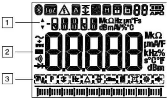
- Secondary display.
- Main display.
- Bar graph (matches the reading on the main display).
4.5 Display icons and indicators
| LoZ | Indicates that the meter is measuring stabilized voltage. |
 | Indicates that the measured voltage is greater than 30 V (AC or DC). |
 | Indicates that the Auto select mode is active. |
| [5H6WX] | Indicates that the meter is displaying maximum reading values. |
| [2084] | Indicates that the meter is displaying minimum reading values. |
 | Indicates that the meter is displaying the average reading. |
| [X78A] | Indicates that the meter is displaying peak maximum values. |
| [HS7] | Indicates that the meter is displaying peak minimum values. |
 | Indicates that the meter is in Auto range mode. |
 | Indicates that the meter is in Hold mode. |
 | Indicates that the meter is in Locked mode. |
 | Indicates the active memory location (1-99). |
| [AZW] | Indicates the battery voltage status. |
 | Indicates that the auto power off function is enabled. |
| [DSKH] | Indicates that the meter is measuring AC current or voltage |
| [TS4K] | Indicates that the meter is measuring DC current or voltage |
 | Indicates that the meter is measuring AC+DC current or volt |
| [XK32] | Indicates that the continuity function is active. |
| [OKDT] | Indicates that the diode test function is active. |
 | VFD mode icon. |
 | Peak mode icon. |
 | Min/Max/Avg mode icon. |
 | Frequency mode icon. |
 | Relative mode icon. |
 | 4000/40 000 digit selection. |
 | dBm mode icon. |
 | 99-point Manual Data Recording mode icon. |
4 Description
 | 10,000 point Automatic Data Recording (Sampling) mode icon |
 | Setup mode icon. |
 | Silent mode icon. |
4.5.1 Probe indicator
When the probe leads are not plugged into the correct jack sockets for the measurement selected by the function switch, PROBE is displayed.
4.5.2 Out-of-range warning
If the input is over/under the full-scale range in Manual range mode, or if the signal has exceeded the maximum/minimum input in Auto range mode, OL is displayed.
5 Operation
Note Before operating the device, you must read, understand, and follow all instructions, dangers, warnings, cautions, and notes.
| NOTE |
| When the meter is not in use, the function switch should be set to the position. |
| NOTE |
| When connecting the probe leads to the device under test, connect the tive lead before connecting the positive lead. When removing the probe I remove the positive lead before removing the negative lead. |
5.1 Powering the meter
- Set the function switch to any position to switch on the meter.
- If the battery indicator shows that the battery voltage is low or if the meter does not power on, replace the battery. See section 6.2 Battery replacement, page 28.
5.1.1 Auto power off
The meter enters sleep mode after a programmable number of minutes of inactivity, see section 5.11.10 Setup mode, page 24.
The meter beeps three times 10 seconds before powering off. Press any button or turn the function switch to prevent the meter from powering off. The auto power off time-out is then reset.
5.2 Auto/Manual select mode
In Auto select mode, the meter attempts to automatically select the proper operating mode based on the input signal:
If the function switch is set to the m or position, the meter attempts to determine if the AC or DC mode should be used.
Auto select mode is the default mode of operation. When a new function is selected with the function switch, the starting mode is Auto select and the cator is displayed.
To enter Manual select mode, press the button. To manually select the operating mode, press the button repeatedly.
To enter Auto select mode, press and hold the button until the indicator is displayed.

NOTE
Note that the DM93-2 Data Recording feature cannot be used when the meter is in the Auto Select Mode. To use the Data Recorder please set the meter to the Manual Select mode first.
5.3 Auto/Manual Range mode
In Auto Range mode, the meter automatically selects the most appropriate measurement scale. In Manual Range mode, the desired range (scale) is set manually. When Auto Range is the default mode of operation, for a given function select by the function switch, indicator is displayed.
To switch to Manual Range mode from Auto Range mode, press button momentarily. The indicator will switch off and the button can then be used to step through the available ranges manually.
To switch to Auto Range mode from Manual Range mode, press and hold the RANGE button until the meter beeps and display the indicator.
To switch to Auto Range mode from Auto Sense mode, press button.
5.4 Voltage measurements
- Set the function switch to one of the following positions:
• for high voltage measurements.
• for low voltage measurements.
- LoZ for voltage measurements using the meter's low input impedance mode. The LoZ indicator is displayed.
- Insert the black probe lead into the negative terminal and the red probe lead into the positive terminal.
- Use the MODE button to select AC, DC, or AC+DC voltage measurement.
- The indicator will be displayed for AC measurements.
- The indicator will be displayed for DC measurements.
- The ± indicator will be displayed for AC+DC measurements.
- Connect the probe leads in parallel to the part under test.
- Read the voltage value on the display.
5.5 Resistance measurements

WARNING
Do not do diode, resistance, or continuity tests before you remove the power from the capacitors and the other devices (when you do a test during a measurement). Injury to persons can occur.
- Set the function switch to the position.
- Ensure that the meter is set to resistance measurement. The unit will be displayed.
If the or indicator is displayed, press the button repeatedly until the Ω unit is displayed. - Insert the black probe lead into the negative terminal and the red probe lead into the positive terminal.
- Touch the tips of the probe across the circuit or component under test.
- Read the resistance value on the display.
5.6 Continuity test

WARNING
Do not do diode, resistance, or continuity tests before you remove the power from the capacitors and the other devices (when you do a test during a measurement). Injury to persons can occur.
- Set the function switch to the position.
- Use the MODE button to select continuity measurement. The indicator will be displayed.
- Insert the black probe lead into the negative terminal and the red probe lead into the positive terminal.
- Touch the tips of the probe across the circuit or component under test.
- If the resistance is 30 ± 5 (nominal) or less, the meter beeps.

NOTE
This threshold is user selectable in the SET UP menu under the Cntin setting:
- Range: 10–50 Ω.
- Increment: 1.
- Default: 30 Ω.
5.7 Diode testing

WARNING
Do not do diode, resistance, or continuity tests before you remove the power from the capacitors and the other devices (when you do a test during a measurement). Injury to persons can occur.
The meter checks diodes using an alternating test signal sent through the diode in both directions. This allows the user to check the diode without having to reverse the polarity manually. The meter display will show ±0.4-0.8V for a good component or O.L for a bad (opened or shorted) component. See Figure 5.1.
5 Operation
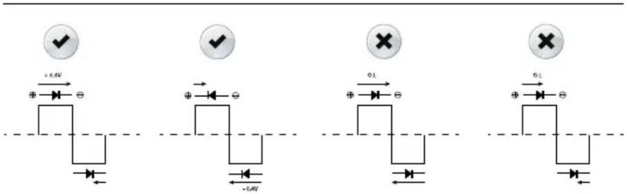
Figure 5.1 Diode testing
-
Set the function switch to the diode position.
-
Insert the black probe lead into the negative terminal and the red probe lead into the positive terminal.
-
Use the MODE button to select the diode test function. The diode indicator will be displayed.
-
Touch the tips of the probe across the diode or semiconductor junction unde test.
-
If the reading is between ±0.40 and +0.80 V, the component is good; an O. display indicates a defective component.
5.8 Capacitance measurements
| WARNING |
| Do not take capacitance measurements before you have removed the from the capacitor or other device or circuit during a test. Injury to p occur. |
- Set the function switch to the position.
- Use the MODE button to select capacitance measurement. The F (Farad) unit will be displayed.
- Insert the black probe lead into the negative terminal and the red probe lead into the positive terminal.
-
Touch the tips of the probe across the part under test.
-
Read the capacitance value on the display.
| NOTE |
| For very large capacitance values, it may take several minutes for measurement to settle and the final reading to stabilize. |
5.9 Type K temperature measurements
- Set the function switch to the position.
- Use the MODE button to select temperature measurement. The °F or °C unit will be displayed.
- While observing the polarity, insert the thermocouple adapter into the negative COM terminal and the positive terminal.
- Touch the tip of the thermocouple to the part under test. Keep the thermocouple tip on the part until the reading on the display stabilizes.
- Read the temperature value on the display.
- To avoid electrical shock, disconnect the thermocouple adapter before turning the function switch to another position.
5.10 Current measurements
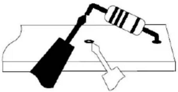
Current is measured by disconnecting the part under test and connecting the probe leads in series with the part, see Figure 5.2.
natural_image
Simple line drawing of a resistor and a hammer on a base (no text or symbols)Figure 5.2 Disconnected component
-
Set the function switch to the position.
-
Insert the black probe lead into the negative terminal and the red probe lead into one of the following positive terminals:
• A for high current measurements.
• mA for low current measurements.
-
Use the MODE button to select AC, DC, or AC+DC voltage measurement.
-
The indicator will be displayed for AC measurements.
- The indicator will be displayed for DC measurements.
-
The ± indicator will be displayed for AC+DC measurements.
-
Connect the probe leads in series with the part in accordance with Figure 5.
- Read the current value on the display.
5.11 Extended functionality
In addition to the basic measurements, the meter can be set to different modes for extended functionality.
5.11.1 Selecting the mode
The mode icons applicable for the selected measurement type are displayed in the lower part of the display. When a mode is enabled, the icon is framed.

Figure 5.3 Mode icons (AC voltage measurements): Peak mode and Silent mode are enabled
- Press the ◀ or ▶ button to navigate to the desired mode icon. The currently selected icon will flash.
- Press the OK button to enable the selected (flashing) mode.
- Press the ▲ or ▼ button to step through the mode options. Refer to the section related to the specific mode for detailed instructions.
- Press the OK button to disable the selected (flashing) mode.
5.11.2 VFD mode (ACV and ACA only)
In VFD (variable-frequency drive) mode, high-frequency noise is eliminated from the voltage measurement by a low-pass filter. VFD mode is available when measuring AC voltage or AC current.
- Select VFD and enable VFD mode as described in section 5.11.1 Selecting the mode, page 20.
5.11.3 Peak mode (ACV and ACA only)
In Peak mode, the meter captures and displays the positive and negative peak values, and updates only when a higher/lower value is registered. The response time of the analog Peak circuit is 200 microseconds.
- Select and enable Peak mode as described in as described in section 5.11.1 Selecting the mode, page 20.
- Press the ▲ or ▼ button to toggle between the display of Peak Max and Peak Min.
- In Peak Max mode, the indicator is displayed. - In Peak Min mode, the indicator is displayed.
- Press the HOLD button to pause the Peak mode. Press again to continue.
5.11.4 Min/Max/Avg mode
In Min/Max/Avg mode, the meter captures and displays the minimum or maximum values and updates only when a higher/lower value is registered. The metal also averages the total sum of all recorded values.
- Select 📄 and enable MIN/MAX/AVG mode as described in section 5.11.1 Selecting the mode, page 20.
- Press the ▲ or ▼ button to cycle through the minimum, maximum, and average reading displays. The corresponding icons are displayed: or
- Press the HOLD button to pause the Min/Max/Avg mode. Press again to continue.
5.11.5 Frequency mode (ACV and ACA only)
In Frequency mode, the frequency is displayed in the main display and the period is displayed in the secondary display. Frequency mode is available when measuring AC voltage or current.
- Select Hz and enable Frequency mode as described in section 5.11.1 Selecting the mode, page 20.
5.11.6 Relative mode
In Relative mode, the difference ( ) between the current reading and a stored reference value is displayed in the main display. The reference value is displayed in the secondary display.
Select △ and enable Relative mode as described in section 5.11.1 Selecting the mode, page 20.
5.11.7 dBm mode (ACV only)
The decibel (dB) is a logarithmic unit that expresses the magnitude of a physical quantity relative to a specified or implied reference level. In dBm mode, the met displays AC voltage measurements in dB or dBm on the secondary display.
dB and dBm are defined as follows:
-
dB = 20 log A(d/1).
• dBm = 20 log AD(√0.7746). -
Select dBm and enable dBm mode as described in section 5.11.1 Selecting the mode, page 20.
-
Press the ▲ or ▼ button to toggle between the display of dB and dBm.
5.11.8 Manual Data Recording mode
The meter has 99 memory locations for the storage of measurement data.
-
Select 📄 and enable Manual Data Recording mode as described in section 5.11.1 Selecting the mode, page 20.
-
Press the ▲ or ▼ button to cycle through the mode options SAVE, LOAD, and CLEAR shown on the secondary display.
-
Press the OK button to activate the displayed option:
- SAVE: The data on the main display is saved to the memory location shown by the 88 indicator in the upper part of the display.
- LOAD: The data stored in the memory location shown by indicator is displayed. Use theor button to change the memory location. Press the ← button to exit the load function.
- CLEAR: The data in all memory locations is cleared.
5.11.9 Automatic Data Recording mode
In Automatic Data Recording mode, the meter records measurement data at the user-programmed sampling rate. The recorded data can be recalled later for review. Up to 10,000 records can be recorded into memory. The sampling rate can be set to a value in the range 1 to 600 seconds.
- Set the meter to Auto Range mode as described in section 5.3 Auto/Manual Range mode, page 15.
- Select 🔒 and press the button to enter logging mode.
-
Press the ▲ or ▼ button to cycle through the mode options START, VIEW, SEND, and RATE shown on the secondary display.
-
Press the button to activate the displayed option:
- VIEW: The secondary display shows the current memory location. The main display shows the data stored in the current memory location. Use the ▲ or ▼ button to change the memory location. Use ◀ or button to change the memory location to the beginning or end. Press the ← button to exit the view function.
- RATE: Press the or button to change the sampling rate.
- SEND: Pair the DM93-2 meter to your mobile device running the METER-LiNK application via Bluetooth. Refer to the METERLiNK user manual, available on the FLIR support site, for application instructions. When ready to send, press the button in SEND, on the DM93-2 meter.
- START: Press the button to start the Automatic Data Recorder. Press the button again to pause the Automatic Data Recorder. Momentarily press the button to stop the Automatic Data Recorder. Press and hold the button to stop data recording and exit to the main display mode. Data recorded up to this point will be stored in the lected location.

NOTE
For fast sampling rate settings (1 or 2 seconds) it is possible for data points be lost while the meter is in the process of auto-ranging. Dashes will be shown in place of data in these rare cases. To minimize this likelihood use a slower sampling rate setting.
5.11.10 Setup mode
In Setup mode, you can define the settings for various meter options:
- Auto power off (indicated by the text APO): A mode where the time period after which the meter enters sleep mode can be set. The range is 1 to 30 nutes, or Off. The factory default is 10 minutes.
-
Auto backlight off (indicated by the text b.Lit): A mode where the time period after which the backlight turns off can be set. The range is 1 to 30 minutes Off. The factory default is 5 minutes.
-
Continuity threshold (indicated by the text Cntin): A mode where the threshold for continuity tests can be set.
-
Auto hold (indicated by the text A.Hold): A mode where auto hold mode and normal hold mode can be set. For more information about these modes, see section 5.12 Normal hold mode and Auto hold mode, page 25.
-
Select ⚙️ and enable Setup mode as described in section 5.11.1 Selecting the mode, page 20.
- Press the ▲ or ▼ button to cycle through the mode options APO, b.Lit, Cntin, AHold, and RESET shown on the secondary display.
-
Press the OK button to activate the displayed option:
-
APO: Press the or button to change the auto power off time.
- b.Lit: Press the or button to change the auto backlight off time.
- Cntin: Press the or button to change the continuity threshold.
- A.Hold: Press the or button to set up auto mode and normal mode. On means that the hold mode is auto hold mode. Off means that the ho mode is normal hold mode.
- RESET: Press the OK button to reset the settings to the factory default.
5.11.11 Silent mode
In Silent mode, the alert beeper is disabled. Silent mode does not affect the continuity beeper.
Select and enable Silent mode as described in section 5.11.1 Selecting the mode, page 20.
5.12 Normal hold mode and Auto hold mode
The meter has two types of hold modes:
- Normal hold mode.
- Auto hold mode.
5.12.1 Normal hold mode
In Normal hold mode, the meter freezes and displays the last reading from the main display and continues to display this value.
To enter/exit Normal hold mode, press the button. In Hold mode, the indicator is displayed.
5.12.2 Auto hold mode
In Auto hold mode, the secondary display freezes the last reading from the main display and continues to display this value. The current reading is displayed on the main display. The held reading (on the secondary display) will not change unless the difference between this held reading and any new reading is greater than 50 digits.
Auto hold limit:
• Function switch in V position: <0.1 V.
• Function switch in LoZ position: <0.1 V.
• Function switch in mV position: <1 mV.
• Function switch in other positions: no limit.
To enter/exit Auto hold mode, press the button. In Auto hold mode, the indicator is displayed and flashing.
5.13 Locked mode
In Locked mode, the meter ignores all button presses except The auto power off function, see section 5.1.1 Auto power off, page 14, is disabled in Locked mode.
Press and hold the HOLD button for 3 seconds to enter/exit Locked mode.
In Locked mode, the indicator is displayed.
5.14 Streaming measurement data using METERLINK
5.14.1 General
You can stream measurement data to a mobile device using the METERLINK app. The app is available from the Apple Store® (iOS) or from Google Play™ (Android).
5.14.2 Procedure
- Download the METERLiNK app to your mobile device and open the app.
- Power the meter and select the desired measurement mode.
- Press the meter's Bluetooth button to enable communications.
5 Operation
- Follow the instructions and prompts on the METERLINK app screens.
6.1 Cleaning and storage
Clean the meter with a damp cloth and mild detergent; do not use abrasives or solvents.
If the meter is not to be used for an extended period, remove the batteries and store them separately.
6.2 Battery replacement
- To avoid electrical shock, disconnect the meter if connected to a circuit, remove the probe/thermocouple leads from the terminals, and set the function switch to the OFF position before attempting to replace the batteries.
- Unscrew and remove the battery compartment cover.
- Replace the six standard AAA batteries, observing correct polarity.
- Secure the battery compartment cover.
6.3 Fuse replacement
When a fuse is blown, the meter displays the word 'FUSE'.
The fuses are accessed via the battery compartment cover.
6.4 Disposal of electronic waste
Electrical and electronic equipment (EEE) contains materials, components and substances that may be hazardous and present a risk to human health and the environment when waste electrical and electronic equipment (WEEE) is not handled correctly.
Equipment marked with the below crossed-out wheeled bin is electrical and electronic equipment. The crossed-out wheeled bin symbol indicates that waste electrical and electronic equipment should not be discarded together with unseparated household waste, but must be collected separately.
For this purpose all local authorities have established collection schemes under which residents can dispose waste electrical and electronic equipment at a recycling centre or other collection points, or WEEE will be collected directly from households. More detailed information is available from the technical administration of the relevant local authority.
7.1 General specifications
Maximum voltage applied to any terminal: 1000 V DC or 1000 V AC RMS.
Display count: 4000/40 000.
Polarity indication: Automatic, positive implied, negative indicated.
Over-range indication: OL.
Measuring rate: 10 samples per second.
Power requirements: 6 × 1.5 V AAA alkaline batteries.
Battery life: Approximately 100 hours with alkaline batteries (with backlight, work light, and Bluetooth off).
Low battery voltage: Approximately 7.0 V.
Auto power off: Default 10 minutes.
Operating ambient temperatures and relative humidity:
- -10 to 30^ (14-86°F), <85% RH.
- 30–40°C (86–104°F), <75% RH.
- 40–50°C (104–122°F), <45% RH.
Storage temperature and relative humidity: -30 to 60°C (-22 to 140°F), 0–80% RH (batteries not fitted).
Temperature coefficient: 0.1 × (specified accuracy)/^, <18^, >28^ .
Operating altitude: 2000 m (6550 ft.).
Calibration cycle: once per year.
Weight: 601 g (1.33 lb.) including batteries.
Dimensions (H × W × L): 60.7 mm × 98.1 mm × 207.1 mm (2.4 in. × 3.9 in. in.) with holster.
Safety: Complies with IEC 61010-1 CAT IV—600 V, CAT III—1000 V, IEC 610102-033.
Dust-proof and splash-proof to IP54.
The Bluetooth range is 10 m (32 ft.) maximum.

| CAT Application field | |
| I Circuits not connected to mains | |
| II | Circuits directly connected to a low voltage installation |
| III Building installation | |
| IV | Source of the low-voltage installation |
EMC: EN 61326-1.
Altitude: 2000 m (6561 ft.).
Pollution degree: 2.
Shock vibration: Per MIL-PRF-28800 for a Class 2 instrument.
Drop protection: 3 m (9.8 ft.).
7.2 Electrical specifications
- Accuracy is ±(% of reading + number of digits (dgt)) at 18–28°C (64.4–82.4°F) (<80% RH).
- For specifications in the 4 3/4 -digit mode, multiply the number of digits by 10.
- For the best measurements, use the REL function to compensate for offsets.
Table 7.1 Voltage. Resolution of specifications in the 3 34 -digit mode.
| Mode Range | Accuracy | |||
| DC | 40.00 mV 0.05%+3d | |||
| 400.0 mV | 0.05%+1d | |||
| 4.000 V | ||||
| 40.00 V | ||||
| 400.0 V | ||||
| 1000 V | ||||
| 40 Hz to 70 Hz | 70 Hz to 1 kHz | 1 kHz to 5kHz | ||
| AC1 | 40.00 mV | 0.5% + 2d | 1.0% + 4d 2.0% + 4d | |
| 400.0 mV | ||||
| 4.000 V | ||||
| 40.00 V | ||||
| 400.0V 0.5% | + 2d 1.0% + | 4d 2.0% + 4d | 2 | |
| 1000 V | 0.5% + 2d | 1.0% + 4d | Unspecified | |
- Below 10% of range, add 10d to accuracy.
- Frequency range 1k to 2k Hz.
Input protection: 1000 V DC or 1000 V AC RMS
Input impedance:
• mV: 10 MΩ, <100 pF.
• V: 10 MΩ, <100 pF.
Bandwidth: 40 Hz to 5 kHz.
Minimum resolution: 1 V in the 40 mV range.
CMRR/NMRR (common/normal mode rejection ratio):
• V AC: CMRR > 60 dB at DC, 50 Hz/60 Hz.
• V DC: CMRR > 100 dB at DC, 50 Hz/60 Hz.
- NMRR > 50 dB at DC, 50 Hz/60 Hz.
AC conversion type: AC coupled, true RMS responding, calibrated to the sine wave input. For non-sine waves, add the following crest factor corrections:
- For a crest factor of 1.4–2.0, add 1.0% to the AC accuracy.
- For a crest factor of 2.0–2.5, add 2.5% to the AC accuracy.
- For a crest factor of 2.5–3.0, add 4.0% to the AC accuracy.
Table 7.2 Current. Resolution of specifications in the 3 34 -digit mode.
| Mode Range | Accuracy | |||
| DC | 40.00 mA | 0.2%+1d400.0 mA | ||
| 4.000 A | ||||
| 10.00 A 0.2% | +2d | |||
| 40 Hz to 70 Hz | 70 Hz to 1 kHz | 1 kHz to 5 kHz | ||
| AC1 | 40.00 mA | 1.0%+2d 2.0% | +4d 2.0%+4d | 2 |
| 400.0 mA | ||||
| 4.000 A | 1.0%+2d 2.0% | +4d | Unspecified | |
| 10.00 A | ||||
- Below 5% of the AC range, add 20 dgt to the accuracy.
- Below 10% of range, add 10 d to accuracy
Input protection: Equipped with a high-energy fuse.
- mA: 440 mA, 1000 V IR 10 kA fuse (Bussmann DMM-B-44/100)
• A: 11 A, 1000 V IR 20 kA fuse (Bussmann DMM-B-11A)
Input impedance:
- mA: 1 Ω at mA input.
• A: 10 mΩ at A input.
Bandwidth: 40 Hz to 5 kHz.
Minimum resolution: 1 A in the 40 mA range.
Maximum measuring time: 1 minute at A input, 10 minutes at mA input. Rest time is 20 minutes minimum.
AC conversion type: The AC conversion type is the same as for the voltage.
Table 7.3 AC additional specifications
| Mode Range Accuracy | ||
| AC+DC | Same as V and A + (3.0% + | AC accuracy + 1.0% |
| VFD | AC accuracy for 40–400 Hz | |
| Peak hold AC accuracy | 100 dgt) for 40Hz to 1kHz | |
| Low-Z Same as V Accuracy + 1.0% | ||
The cut-off frequency of VFD: 800 Hz (-3 dB point).
Attenuation characteristic of VFD: Approx. -24 dB.
Table 7.4 Frequency Counter
| Range Resolution Accuracy | |
| 400.00 Hz 0.01 Hz | |
| 4.0000 kHz 0.1 Hz | |
| 40.000 kHz 1 Hz | |
| 100.00 kHz 10 Hz |
Minimum sensed frequency: 5 Hz.
Table 7.5 Frequency counter sensitivity
| Function Range | Sensitivity | (peak to peak)5 Hz to 10 kHz | Sensitivity(peak to peak)10–100 kHz |
| mV | 40.00 mV 10 mV | 10 mV | |
| 400.0 mV 100 mV | 100 mV | ||
| V | 4.000 V 1 V 1 V | ||
| 40.00 V 10 V 10 V | |||
| 400.0 V 100 V 100 V | |||
| 1000 V 600 V Unspecified | |||
| mA | 40.00 mA 10 mA | Unspecified | |
| 400.0 mA 100 mA | |||
| A | 4.000 A 1 A | Unspecified | |
| 10.00 A 6 A |
Table 7.6 Resistance. Resolution of specifications in the 3 34 -digit mode.
| Range Resolution Accuracy | ||
| 400.0 Ω 100 mΩ ±(0.2% + 2 dgt) | ||
| 4.000 kΩ | 1 Ω | ±(0.2% + 1 dgt) |
| 40.00 kΩ | 10 Ω | |
| 400.0 kΩ | 100 Ω | |
| 4.000 MΩ 1 kΩ | ±(1.0% + 1 dgt) | |
| 40.00 MΩ 10 kΩ | ±(2.0% + 20 dgt) | |
Input protection: 1000 V DC or 1000 V AC RMS.
Maximum open circuit voltage: Approx. 2.5 V.
Maximum short test current: Approx. 0.1 mA.
Table 7.7 Continuity check. Resolution of specifications in the 3 34 -digit mode.
| Range Resolution Accuracy | |
| 400.0 Ω 100 mΩ ±(0.2% + 2 dgt) |
Input protection: 1000 V DC or 1000 V AC RMS.
Maximum open circuit voltage: Approx. 2.5 V.
Maximum short test current: Approx. 1 mA.
Continuity threshold: Default <30 Ω.
Continuity response time: 10 ms for <10 Ω, 200 ms for >10 Ω.
Continuity indicator: 2.7 kHz tone buzzer.
Table 7.8 Diode test
| Range Resolution Accuracy | ||
| 2.000 V 1 mV ±(1.5% | + 2 dgt) | |
Input protection: 1000 V DC or 1000 V AC RMS.
Maximum open circuit voltage: Approx. ±2.5 V.
Maximum short test current: Approx. ±1 mA.
Table 7.9 Capacitance
| Range Resolution Accuracy | |
| 40.00 nF 10 pF ±(1.2% + 20 dgt) | |
| 400.0 nF 100 pF ±(0.9% + 10 dgt) | |
| 4.000 μF 1 nF ±(0.9% + 5 dgt) | |
| 40.00 μF 10 nF | |
| 400.0 μF 100 nF | |
| 4.000 mF 1 μF ±(1.2% + 20 dgt) | |
| 40.00 mF 10 μF ±(2.0% + 20 dgt) |
Input protection: 1000 V DC or 1000 V AC RMS.
Table 7.10 Temperature
| Range Resolution Accuracy | ||||||||
| -328°F to 2192°F 0.1°F 1.0% + 36d | ||||||||
| -200°C to 1200°C 0.1°C 1.0% + 20d | ||||||||
Input protection: 1000 V DC or 1000 V AC RMS.
| NOTE |
| Accuracy specification assumes the ambient temperature is stable to ±1°C (±1.8°F). For ambient temperature changes of ±5°C (±9°F), the rated accuracy applies after 1 hour.The accuracy specifications apply when the backlight and worklight have been off for one hour. Heat from these light sources can affect measurement accuracy. |
8 Technical support for external meters
| Repair, Calibration, and Technical Support | https://support.flir.com |
9 Warranty
This product is protected by FLIR's Limited Lifetime Warranty. Visit www.flir.com/testwarranty to read the Limited Lifetime Warranty document. Register your product at the website.
A note on the technical production of this publication
This publication was produced using XML — the eXtensible Markup Language. For more information about XML, please visit http://www.w3.org/XML/
A note on the typeface used in this publication
This publication was typeset using Linotype Helvetica™ World. Helvetica™ was designed by Max Miedinger (1910–1980)
LOEF (List Of Effective Files)
T501563.xml; en-US; AA; 93040; 2023-09-14
Website
http://www.flir.com
Customer support
http://support.flir.com
Copyright
© 2023, FLIR Systems, Inc. All rights reserved worldwide.
Disclaimer
Specifications subject to change without further notice. Models and accessories subject to regional market considerations. License procedures may apply. Products described herein may be subject to US Export Regulations. Please refer to exportquestions@flir.com with any questions.
Publ. No.: T810631
Release: AA
Commit: 93221
Head: 93387
Language: en-US
Modified: 2023-09-14
Formatted: 2023-09-26


- User's manual FLIR DM93-2
- Disclaimers. . . . . . . . . . . . . . . . . . . . . . . . . . . . . . . . . . . . . . . . . .
- Safety information....2
- Introduction 7
- Description 8
- Operation....14
- Copyright
- Quality assurance
- ed, 1.4 Disposal of electronic waste
- Documentation updates
- Safety information
- FCC Compliance
- Industry Canada compliance
- Introduction
- Key features
- Description
- Meter description
- Function buttons
- Display description
- Display icons and indicators
- Probe indicator
- Out-of-range warning
- Operation
- Powering the meter
- Auto power off
- Auto/Manual select mode
- NOTE
- Auto/Manual Range mode
- Voltage measurements
- Resistance measurements
- WARNING
- Continuity test
- Diode testing
- Capacitance measurements
- Type K temperature measurements
- Current measurements
- Extended functionality
- Selecting the mode
- VFD mode (ACV and ACA only)
- Peak mode (ACV and ACA only)
- Min/Max/Avg mode
- Frequency mode (ACV and ACA only)
- Relative mode
- dBm mode (ACV only)
- Manual Data Recording mode
- Automatic Data Recording mode
- Setup mode
- Silent mode
- Normal hold mode and Auto hold mode
- Normal hold mode
- Auto hold mode
- Locked mode
- Streaming measurement data using METERLINK
- General
- Procedure
- Cleaning and storage
- Battery replacement
- Fuse replacement
- Disposal of electronic waste
- General specifications
- Electrical specifications
- Technical support for external meters
- Warranty
- A note on the technical production of this publication
- A note on the typeface used in this publication
- LOEF (List Of Effective Files)
- Website
- Customer support
- Copyright
- Disclaimer
Brand : FLIR
Model : DM93-2
Category : Multimeter