
HPS-28CH84AERI/O1s R32 - Air-conditioner Vivax - Free user manual and instructions
Find the device manual for free HPS-28CH84AERI/O1s R32 Vivax in PDF.

| Type | Air-to-water heat pump outdoor unit (split system) |
| Model Variants | 4 kW, 6 kW, 8 kW, 10 kW, 12 kW, 14 kW, 16 kW |
| Power Supply | 220-240 V~ 50 Hz (1-phase) or 380-415 V 3N~ 50 Hz (3-phase for 12-16 kW) |
| Refrigerant Type | R32 (GWP 675) |
| Factory Refrigerant Charge | 1.50 kg (4-6 kW), 1.65 kg (8-10 kW), 1.84 kg (12-16 kW) |
| Compressor | DC inverter dual rotary |
| Fan Motor | DC motor, horizontal discharge |
| Dimensions (W×H×D) | 1008×712×426 mm (4-6 kW); 1118×865×523 mm (8-16 kW) |
| Net Weight | 60 kg (4-6 kW), 78.5 kg (8 kW), 100 kg (12-14 kW), 116 kg (16 kW) |
| Max Piping Length | 30 m |
| Max Height Difference | 20 m (outdoor unit above indoor) |
| Additional Refrigerant | 20 g/m (4-6 kW) or 38 g/m (8-16 kW) for pipe length >15 m |
| Operating Temperature Range (Heating) | -25°C to +35°C |
| Operating Temperature Range (Cooling) | -5°C to +43°C |
| Control Interface | Wired controller with LCD display and mobile app (MSmartLife) |
| Modes | Cooling, heating, auto, domestic hot water (DHW) |
| Special Functions | Eco mode, weather compensation, timer/weekly schedule, holiday mode, silent mode |
| Safety Features | High/low pressure switch, compressor protection, ground fault circuit interrupter (30 mA), flammable refrigerant detection |
| Maintenance | Periodic cleaning of outdoor coil, check refrigerant pressure, clean filters |
| Warranty | Standard 12 months, extendable up to 36 months with annual service |
Frequently Asked Questions - HPS-28CH84AERI/O1s R32 Vivax
User questions about HPS-28CH84AERI/O1s R32 Vivax
0 question about this device. Answer the ones you know or ask your own.
Ask a new question about this device
Download the instructions for your Air-conditioner in PDF format for free! Find your manual HPS-28CH84AERI/O1s R32 - Vivax and take your electronic device back in hand. On this page are published all the documents necessary for the use of your device. HPS-28CH84AERI/O1s R32 by Vivax.
USER MANUAL HPS-28CH84AERI/O1s R32 Vivax
natural_image
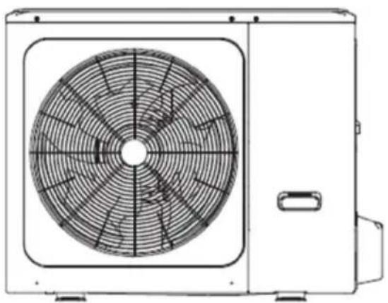
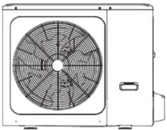
Technical line drawing of a front-mounted air conditioner fan with visible blades and mounting base (no text or symbols)4/6 kW
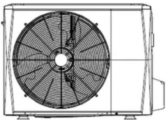
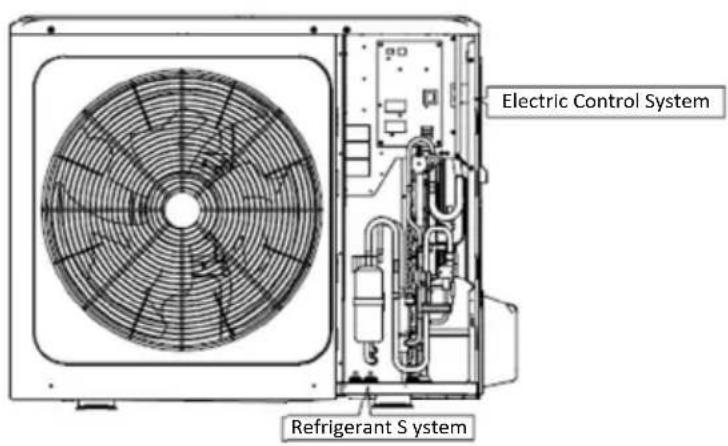
natural_image
Technical line drawing of a front-mounted air conditioner unit with fan blades and vent slots (no text or symbols)8/10/12/14/16 kW
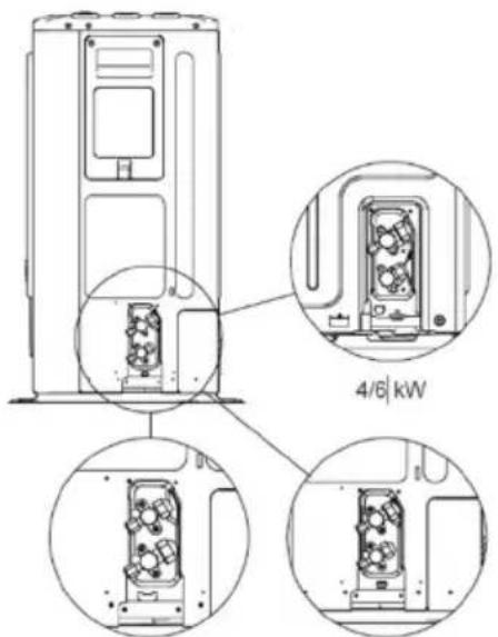
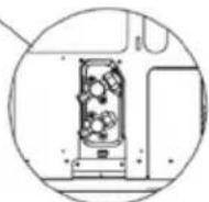
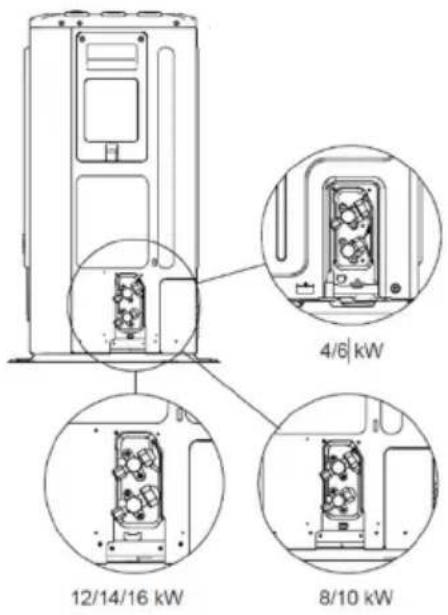
12/14/16 kW
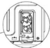
8/10 kW
natural_image
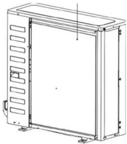
Technical line drawing of a rectangular enclosure with internal compartments and mounting feet (no text or symbols)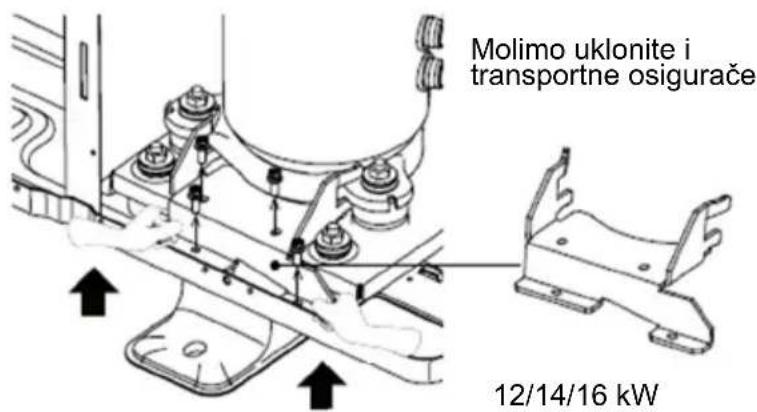
MJERE OPREZA
Ovdje navedene mjere opreza podijeljene su u sljedeće podvrste. One su vrlo važne, stoga ih se pažljivo pridržavajte.
Značenja simbola OPASNOST, UPOZORENJE, OPREZ i NAPOMENA.
i INFORMACIJE
- Pažljivo pročitajte ove upute prije instalacije. Ovaj priručnik držite pri ruci za buduće korištenje.
- Nepravilna instalacija opreme ili pribora može dovesti do strujnog udara, kratkog spoja, curenja, požara ili drugih oštećenja opreme. Uvjerite se da koristite samo one dodatke proizvedene od strane dobavljača, koji su posebno dizajnirani za opremu, a za instaliranje se obavezno obratite profesionalcu.
- Sve aktivnosti opisane u ovom priručniku mora obavljati ovlašteni tehničar. Obavezno nosite odgovarajuću osobnu zaštitnu opremu kao što su rukavice i zaštitne naočale tijekom instalacije jedinice ili obavljanja aktivnosti održavanja.
- Za bilo kakvu pomoć u vezi sa uređajem, obratite se dobavljaču.
natural_image
Warning symbol of a flame inside a triangle (no text or numbers)Oprez: Rizik od požara / zapaljivi materijali.
UPOZORENJE
Servisiranje se smije obavljati samo prema preporuci proizvođača opreme. Održavanje i popravak koji zahtijevaju pomoć drugog kvalificiranog osoblja obavljaju se pod nadzorom osobe nadležne za uporabu zapaljivih rashladnih sredstava.
! OPASNOST
natural_image
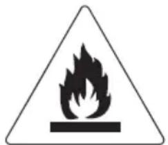
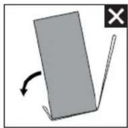
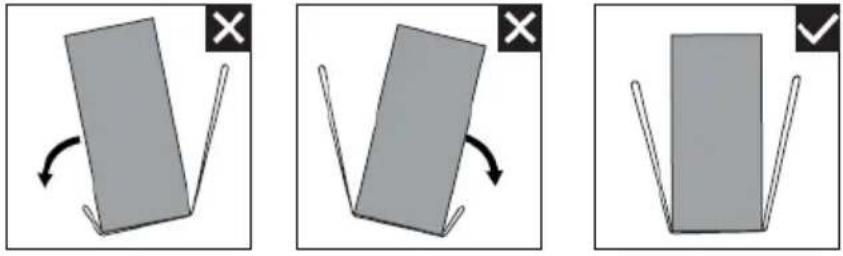
Simple diagram showing a gray rectangular object with an arrow indicating rotation, next to a white checkmark (no text or symbols)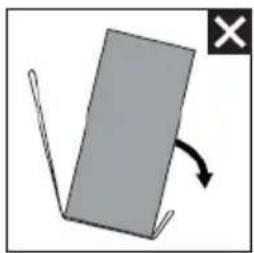
natural_image
Simple diagram of a gray rectangular object with a curved arrow indicating rotation or change, no text or symbols present.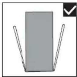
natural_image
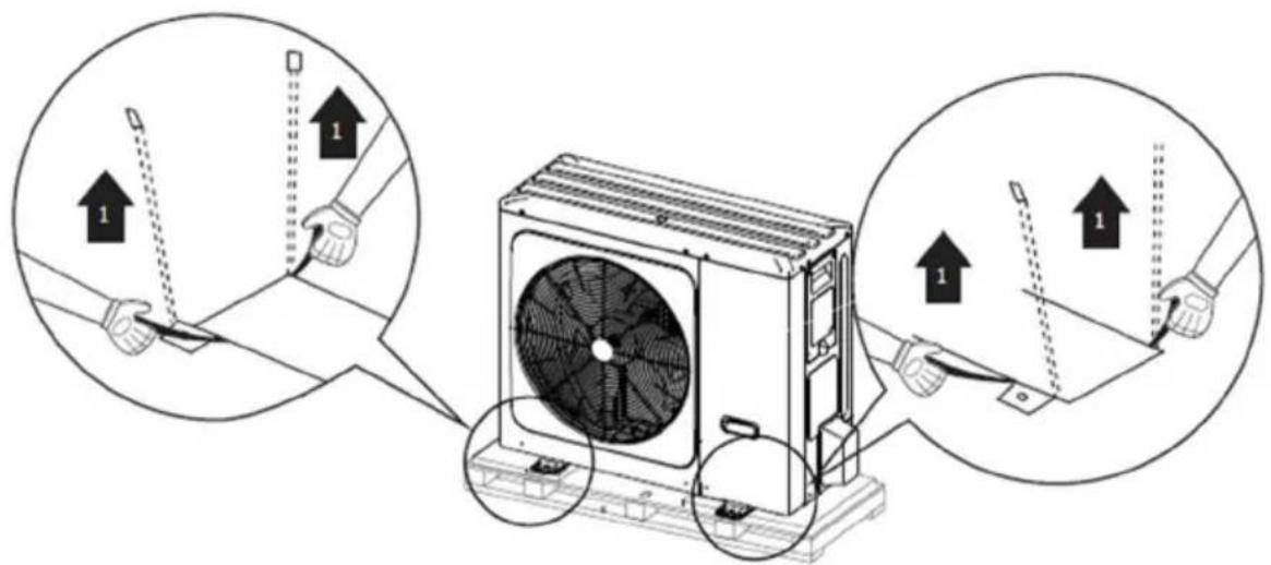
Simple diagram of a gray rectangle with two vertical lines and a checkmark in the corner (no text or symbols)Tijekom rukovanja s uređajem držite obje strane u visini remena. Leđa držite uspravljena.
natural_image
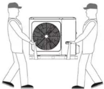
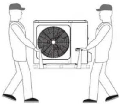
Two workers carrying a large air conditioner unit (no text or symbols visible)Nakon postavljanja jedinice, uklonite remen s jedinice povlačenjem jedne strane remena.
OPREZ
4/6/8/10 kW (jedinica: mm)

NAPOMENA
natural_image
Simple line drawing of a house with a hanging weight and a cross symbol (no text or labels)① Izgradite veliku nadstrešnicu.
② Izgradite postolje.
Ugradite jedinicu dovoljno visoko od tla da se spriječi da se zakopa u snijeg.
Zaštita od sunca
natural_image
Technical line drawing of a front-end air conditioning unit with fan and base (no text or symbols)SI 6-4
8/10/12/14/16 kW
Sl. 6-5
OPREZ
sl. 6-6
| Uređaj | A(mm) |
| 4~16kW ≥2000 |

NAPOMENA
natural_image
Simple icon of a device with two circular ports and a checkmark (no text or symbols)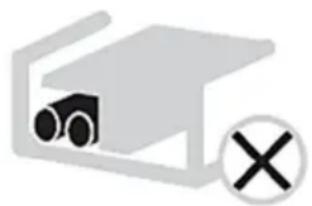
natural_image
Simple line drawing of a vehicle inside a vehicle enclosure with a cross symbol (no text or labels)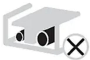
natural_image
Simple icon of a laptop with a magnifying glass and a cross symbol (no text or labels)- Upotrijebite odgovarajući odvijač zatezanjem stezaljki. Manji odvijači mogu oštetiti glavu vijka i spriječiti odgovarajuće zatezanje.
- Prejakim stezanjem stezaljki mogu se oštetiti vijci.
- Priključite prekidač i osigurač na uzemljenje na kabel napajanja.
- Kod ožičenja pazite da se koriste propisane žice, izvedite cjelovite spojeve i učvrstite žice tako da vanjska sila ne može utjecati na stezaljke.
MCA: Maks. Amp kruga (A)
natural_image
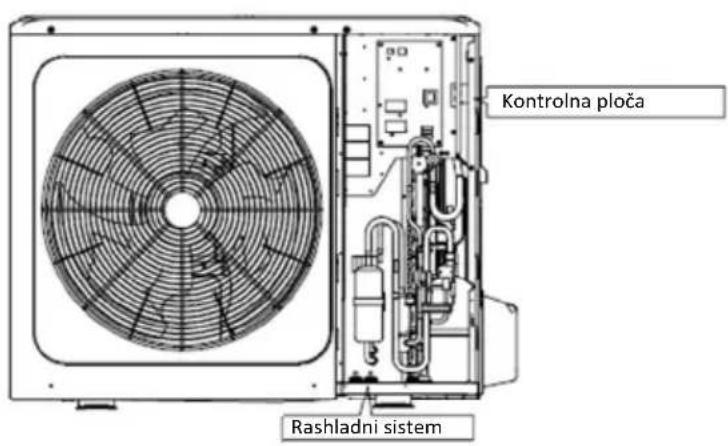
Technical line drawing of a multi-chamber air conditioning unit with fan and cooling unit (no text or symbols)
NAPOMENA
Prekidač strujnog kruga mora biti brzi prekidač brzine od 30 mA (<0,1s). Molimo koristite trostruko zaštićenu žicu.
Završite instalaciju vanjske jedinice
natural_image
Technical line drawing of a fan or air conditioner unit with no visible text or symbolsnatural_image
Technical line drawing of a dual-panel air conditioner unit with fan blades and vent slots (no text or symbols)8/10/12/14/16 kW
Vrata 1: Za pristup kompresoru i električnim dijelovima

UPOZORENJE
natural_image
Technical line drawing of a square fan with visible blades and mounting connectors (no text or symbols)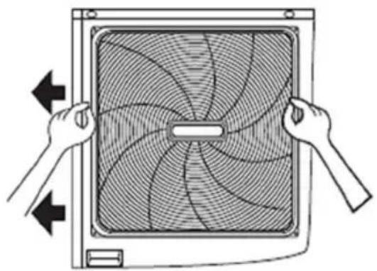
natural_image
Illustration of hands holding a square fan with visible blades and central hub, no text or symbols presentElektronička kontrolna kutija
12/14/16kW 3-phase

NAPOMENA
12\~16kW 1-phase units
1)
PCB A, Pretvarački modul
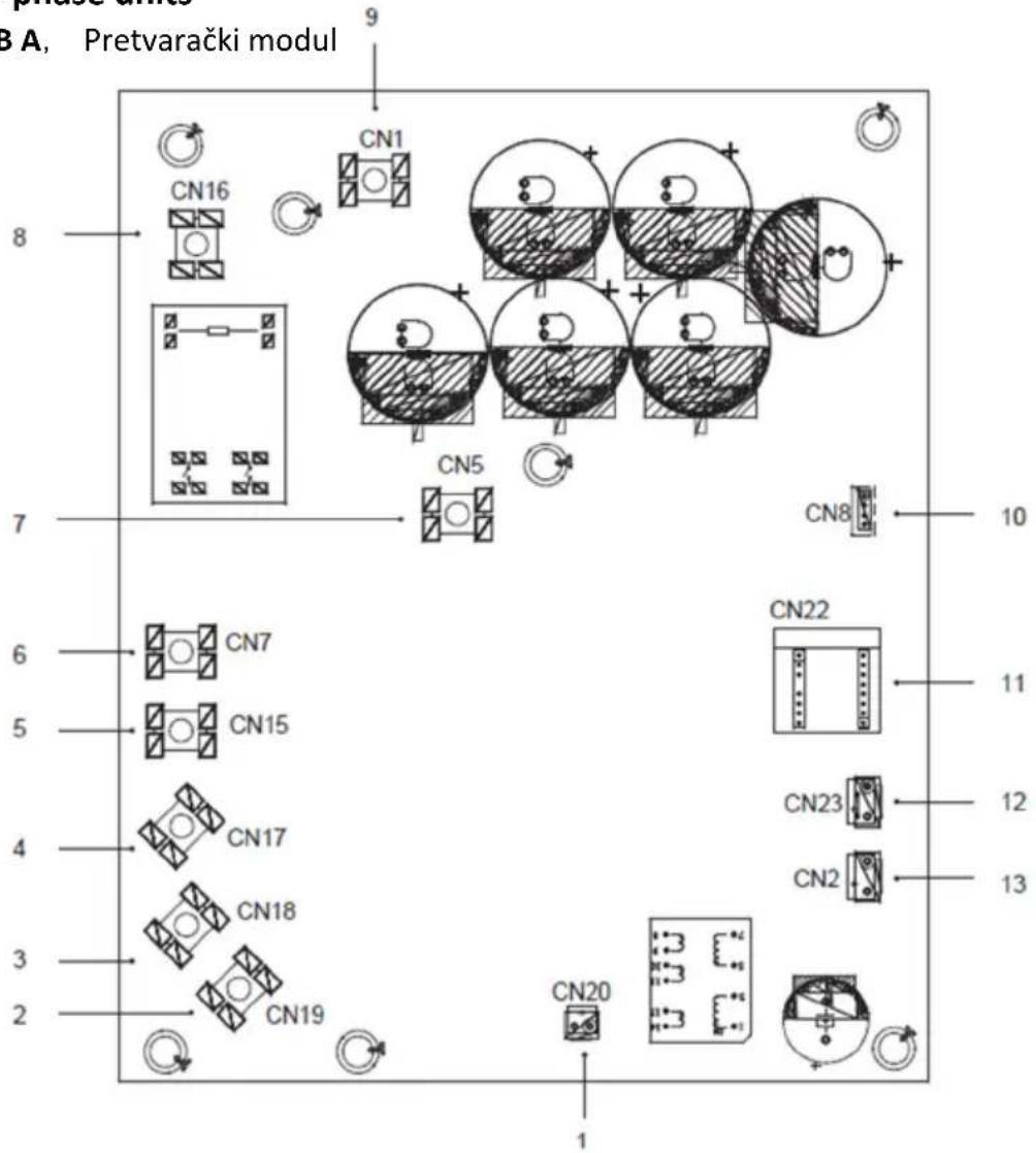
| Kod | Montažna jedinica | Kod | Montažna jedinica |
| 1 | Izlazni priključak za +15V(CN20)) | 8 | Ulaz za napajanje L1(CN16) |
| 2 | Priključak za kompresor W(CN19) | 9 | Ulazni priključak iz P za IPM modul (CN1) |
| 3 | Priključak za kompresor V(CN18) | 10 | Priključak za komunikaciju s PCB B (CN8) |
| 4 | Priključak za kompresor U(CN17) | 11 | PED ploča (CN22) |
| 5 | Ulaz za napajanje L3(CN15) | 12 | Priključak za prekidač visokog tlaka (CN23) |
| 6 | Ulaz za napajanje L2(CN7) | 13 | Priključak za komunikaciju s PCB C(CN2) |
| 7 | Ulazni priključak iz P za IPM modul (CN5) |
line
| Time Point | T1SETC1 | T1SETC2 | | ---------- | ------- | ------- | | T4C1 | High | Low | | T4C2 | Low | Low |Dodatna stranica
Zona 2 – željena temperatura protoka vode
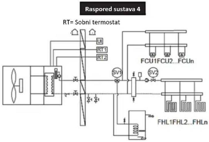
flowchart
graph TD
    A["RF System"] --> B["UT"]
    A --> C["RT1"]
    A --> D["RT2"]
    B --> E["Switch"]
    C --> E
    D --> E
    E --> F["FCU1FCU2...FCUn"]
    F --> G["Switch"]
    F --> H["Switch"]
    G --> I["FHL1FHL2...FHLn"]
    H --> I
    I --> J["Output Line"]
    style A fill:#f9f,stroke:#333
    style F fill:#ccf,stroke:#333
    style G fill:#cfc,stroke:#333
    style H fill:#fcc,stroke:#333
STRUKTURA IZBORNIKA
O strukturi izbornika
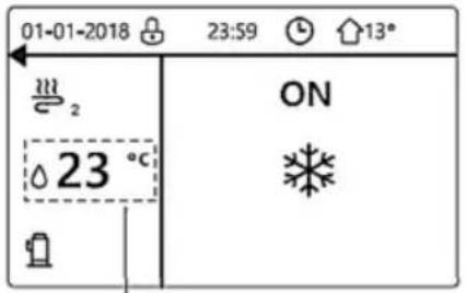
② Sobni termostat je SET DOUBLE ZONE (postavljen dvozonski) (vidi „ROOM THERMOSTAT SETTING“ u „Instalacija i vlasnički priručnik (M-termalna podijeljena unutarnja jedinica)“). Sobni termostat za zavojnicu ventilatora je isključen, sobni termostat za podno grijanje je uključen, a uređaj radi, ali je prikaz OFF (isključen). Prikazuje se sljedeća stranica:
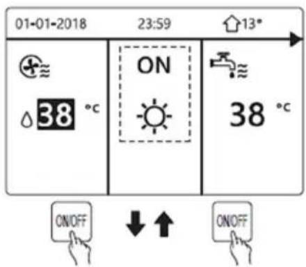

Koristite sučelje za paljenje ili gašenje uređaja za DHW.
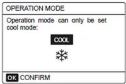
RAD
Radni način
Vidi „Adjusting space operation mode“ (Prilagodba načina rada u prostoru):
Zadana temperatura
PRESET TEMP (zadana temperatura) ima 3 stavke: PRESET TEMP.\WEATHER TEMP, SET\ECO MODE.
ZADANA TEMP. (PRESET TEMP.)
WEATHER TEMP. SET = POSTAVLIANJE TEMPERATURE VODE
Pomaknite se na „NO“, pritisnite „OK“ da biste se vratili na početnu stranicu. Pomaknite se na „YES“, pritisnite „OK“ za ponovno postavljanje WEATHER TEMP. SET.
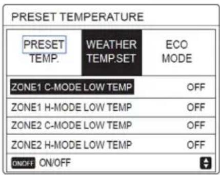
ECO način
ECO MODE koristi se za uštedu energije. Idite na „MENU“ > „PRESET TEMPERATURE“ > „ECO MODE“.
line
| Time | PUMP | |-------|------| | 6:00 | ON | | 6:30 | ON | | 7:00 | ON | | 7:30 | ON | | 8:00 | ON | | 8:30 | ON | | 9:00 | ON | | 9:30 | ON |RASPORED
Primjer:
Šest tajmera je postavljeno na sljedeći način:
| NO. | START | END | MODE | TEMP |
| T1 | 1:00 | 3:00 | DHW | 50°C |
| T2 | 7:00 | 9:00 | HEAT | 28°C |
| T3 | 11:30 | 13:00 | COOL | 20°C |
| T4 | 14:00 | 16:00 | HEAT | 28°C |
| T5 | 15:00 | 19:00 | COOL | 20°C |
| T6 | 18:00 | 23:30 | DHW | 50°C |
Koristite „◀“, „▶“, „▼“, „▲“ da biste se pomaknuli na „YES“, pritisnite „OK“ da biste otkazali tajmer. Ako želite izaći iz CANCEL TIMER, pritisnite „BACK“. Ako je aktiviran TIMER ili WEEKLY SCHEDULE, ikona tajmera „●“ ili tjednog rasporeda „7“ će se prikazati na početnoj stranici.
| 01-01-2018 | 23:59 | 13° |
| 23.5°C | ON | 38°C |
Ako se otkaže TIMER ili WEEKLY SCHEDULE, ikona tajmera „©“ ili tjednog rasporeda „☐” nestat će na početnoj stranici.
| 01-01-2018 | 23:59 | 13° |
| ON | ||
| 23.5°C | 38°C |
i INFORMACIJE
Morate resetirati TIMER/WEEKLY SCHEDULE ako promijenite WATER FLOW TEMP. na ROOM TEMP. ili ROOM TEMP. na WATER FLOW TEMP.
TIMER ili WEEKLY SCHEDULE ne vrijede ako je ROOM THERMOSTAT uključen.
i INFORMACIJE
- Načini ECO ili COMFORT MODE imaju najveći prioritet, TIMER ili WEEKLY SCHEDULE su sljedeći, a PRESET TEMP. ili WEATHER TEMP. SET imaju najmanju važnost.
- PRESET TEMP. ili WEATHER TEMP. SET postaju nevažeći kada postavite ILI-ILI COMFORT. Potrebno je resetirati PRESET TEMP. ili WEATHER TEMP. SET kada isključite ECO ili COMFORT.
- TIMER ili WEEKLY SCHEDULE ne rade kada rade ECO ili COMFORT. TIMER ili WEEKLY SCHEDULE aktiviraju se kada ILI-ILI COMFORT ne rade.
i INFORMACIJE
- TIMER i WEEKLY SCHEDULE imaju isti prioritet. Aktivira se kasnije postavljena funkcija. PRESET TEMP. postaje nevažeće kada rade TIMER ili WEEKLY SCHEDULE. WEATHER TEMP. SET nije pod utjecajem postavke za TIMER ili WEEKLY SCHEDULE.
- PRESET TEMP. i WEATHER TEMP.SET imaju isti prioritet. Kasnije postavljena funkcija je važeća.
i INFORMACIJE
| Setting | Value |
| Holiday Away | ON |
| From | 2 February 2018 |
| Until | 16 February 2018 |
| Operation Mode | Heating |
| Disinfect ON |
i INFORMACIJE
SERVISNI PODACI
i INFORMACIJE
Odaberite „YES“ i pritisnite „OK“ da biste izašli iz izbornika FOR SERVICEMAN.
Aktivirajte WLAN putem sučelja.
Koristite „◀“, „▶“ za pomicanje na „YES“ i pritisnite „OK“ da biste odabrali AP mode.
Odaberite AP Mode na mobilnom uređaju i nastavite slijediti postavke u skladu s naredbama aplikacije.
OPREZ
Nakon ulaska u AP mode, ako on nije povezan s mobilnim telefonom, LCD ikona „ “ će bljeskati 10 minuta 10 minuta i zatim nestati. Ako je povezan s mobilnim telefonom, ikona „ “ će stalno raditi.
Vratite WLAN postavku sučeljem.
Koristite „◀“, „▶“ da biste se pomaknuli na „YES“ i pritisnite „OK“ da biste obnovili WLAN postavku.
Dovršite gornju radnju i bežična konfiguracija je ponovno postavljena.
Postavljanje mobilnog uređaja
- Molimo da potražite „Msmartlife“ u trgovinama APP STORE ili GOOGLE PLAY da biste instalirali aplikaciju.
Prijava/registracija
Kliknite tipku „+“ na desnoj strani početne stranice i registrirajte račun u skladu s vodičem.


Upozorenje i rješavanje problema za mrežne kvarove
line
| Time Point | T1SETC1 | T1SETC2 | | ---------- | ------- | ------- | | T4C1 | High | Low | | T4C2 | Low | Low |Thank you very much for purchasing our product,
Before using your unit, please read this manual carefully and keep it for future reference.
CONTENTS
SAFETY CONSIDERATIONS 4
ACCESSORIES 9 Accessories supplied with the unit 9
BEFORE INSTALLATION 9
IMPORTANT INFORMATION FOR THE REFRIGERANT 10
INSTALLATION SITE 11
Selecting a location in cold climates 13
Prevent sunshine 14
INSTALLATION PRECAUTIONS 14
Dimensions 14 Installation requirements 15
Drain hole position 15
Servicing space requirements 16
INSTALLATION THE CONNECTING PIPE 18
Rrfrigerant piping 18
Leakage Detection 19
Heat insulation 19
Connecting method 20
Remove dirt or water in the pipe 21
Airtight test 21
Air Purge with Vacuum Pump 21
Refrigerant amount to be added 22
OUTDOOR UNIT WIRING 22
Precautions on wiring of power supply 23
Remove the switch box cover 25
To finish the outdoor units insulation 26
OVERVIEW OF THE UNIT 27
Disassambling the unit 27
Electronic control box 28
4\~16W Units 29
TEST RUNNING 36
PRECAUTIONS ON REFRIGERANT LEAKAGE 36
TURN OVER TO CUSTOMER 38
Protection equipment 35
About power cut 35
Heating capacity 35
Compressor protection feature 35
Cooling and heating operation 36
Features of heating operation 36
Deforst in the heating operation 36
Error codes 43
TECHNICAL SPECIFICATIONS 49
INFORMATION SERVICING 51
Note: All the pictures in this manual are just schematic diagrams, the actual is the standard
natural_image
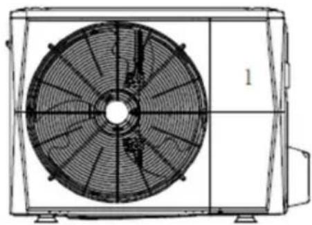
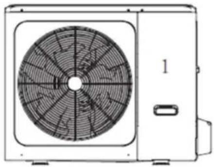
Technical line drawing of a fan assembly with visible blades and mounting base (no text or symbols)4/6 kW
natural_image
Front view of a white industrial air conditioning unit with a circular fan and side panel (no text or symbols visible)8/10/12/14/16 kW
Please remove the hollow plate after installation.
natural_image
Technical line drawing of a rectangular enclosure with internal compartments and mounting feet (no text or symbols)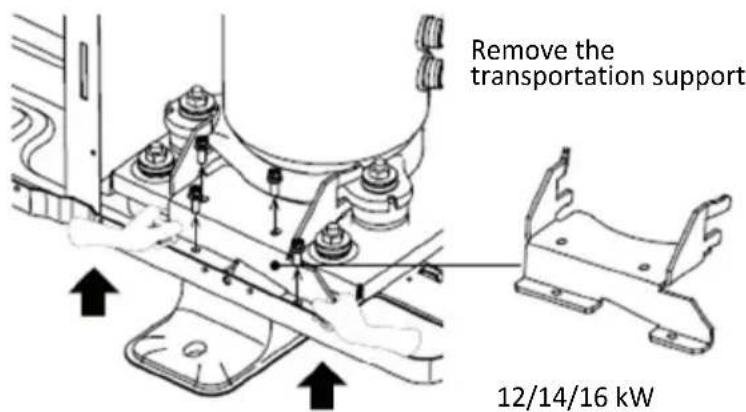
SAFETY PRECAUTIONS
The precautions listed here are divided into the following types. They are quite important, so be sure to follow them carefully.
Meanings of DANGER, WARNING, CAUTION and NOTE symbols.
i INFORMATION
- Read these instructions carefully before installation. Keep this manual in a handy for future preference.
- Improper installation of equipment or accessories may result in electric shock, short-circuit, leakage, fire or other damage to the equipment. Be sure to only use accessories made by the supplier, which are specifically designed for the equipment and make sure to get installation done by a professional.
- All the activitie described in this manual must be carried out by a licensed technician. Be sure to wear adequate personal protection equipment such as gloves and safety glasses while installation the unit or carrying out maintenance activities.
- Contact your dealer for any further assistance
natural_image
Warning symbol of a flame inside a triangle (no text or numbers)Caution: Risk of fire / flammable materials.
WARNING
Servicing shall only be performed as recommended by the equipment manufacturer. Maintenance and repair requiring the assistance of other skilled personnel shall be carried out under the supervision of the person competent in the use of flammable refrigerants.
DANGER
Indicates an imminently hazardous situation which if not avoided, will result in death or serious injury.
WARNING
Indicates a potentially hazardous situation which if not avoided, could result in death or serious injury.

CAUTION
Indicates a potentially hazardous situation which if not avoided, may result in minor or moderate injury.

NOTE
Indicates situations that could only result in accidental equipment or property damage.
 | WARNING | This symbol shows that this appliance used a flammable refrigerant. If the refrigerant is leaked and exposed to an external ignition source, there is a risk of fire. |
 | CAUTION | This symbol shows that the operation manual should be read carefully. |
 | CAUTION | This symbol shows that a service personnel should be handling this equipment with reference to the installation manual. |
 | CAUTION | This symbol shows that a service personnel should be handling this equipment with reference to the installation manual. |
 | CAUTION | This symbol shows that information is available such as the operating manual or installation manual. |

DANGER
- Before touching electric terminal parts, turn off power switch.
- When service panels are removed, live parts can be easily touched by accident.
- Never leave the unit unattended during installation or servicing when the service panel is removed.
- Do not touch water pipes during and immediately after operation as the pipes may be hot and could burn your hands. To avoid injury, give the piping time to return to normal temperature or be sure to wear protective gloves.
- Do not touch any switch with wet fingers. Touching a switch with wet fingers can cause electrical shock.
- Before touching electrical parts, turn off all applicable power to the unit.

WARNING
- Tear apart and throw away plastic packaging bags so that children will not play with them. Children playing with plastic bags face danger of death by suffocation.
- Safely dispose of packing materials such as nails and other metal or wood parts that could cause injuries.
- Ask your dealer or qualified personnel to perform installation work in accordance with this manual. Do not install the unit yourself. Improper installation could result in water leakage, electric shocks or fire.
- Be sure to use only specified accessories and parts for installation work. Failure to use specified parts may result in water leakage, electric shocks, fire, or the unit falling from its mount.
- Install the unit on a foundation that can withstand its weight. Insufficient physical strength may cause the equipment to fall and possible injury.
- Perform specified installation work with full consideration of strong wind, hurricanes, or earthquakes. Improper installation work may result in accidents due to equipment falling.
- Make certain that all electrical work is carried out by qualified personnel according to the local laws and regulations and this manual using a separate circuit. Insufficient capacity of the power supply circuit or improper electrical construction may lead to electric shocks or fire.
- Be sure to install a ground fault circuit interrupter according to local laws and regulations. Failure to install a ground fault circuit interrupter may cause electric shocks and fire.
- Make sure all wiring is secure. Use the specified wires and ensure that terminal connections or wires are protected from water and other adverse external forces. Incomplete connection or affixing may cause a fire.
- When wiring the power supply, form the wires so that the front panel can be securely fastened. If the front panel is not in place there could be overheating of the terminals, electric shocks or fire.
- After completing the installation work, check to make sure that there is no refrigerant leakage.
- Never directly touch any leaking refrigerant as it could cause severe frostbite. Do not touch the refrigerant pipes during and immediately after operation as the refrigerant pipes may be hot or cold, depending on the condition of the refrigerant flowing through the refrigerant piping, compressor and other refrigerant cycle parts. Burns or frostbite are possible if you touch the refrigerant pipes. To avoid injury, give the pipes time to return to normal temperature or, if you must touch them be sure to wear protective gloves.
- Do not touch the internal parts (pump, backup heater, etc.) during and immediately after operation. Touching the internal parts can cause burns. To avoid injury, give the internal parts time to return to normal temperature or, if you must touch them, be sure to wear protective gloves.

CAUTION
- Ground the unit.
- Grounding resistance should be according to local laws and regulations.
- Do not connect the ground wire to gas or water pipes, lightning conductors or telephone ground wires.
-
Incomplete grounding may cause electric shocks.
-
Gas pipes : Fire or an explosion might occur if the gas leaks.
- Water pipes : Hard vinyl tubes are not effective grounds.
-
Lightning conductors or telephone ground wires : Electrical threshold may rise abnormally if struck by a lightning bolt.
-
Install the power wire at least 3 feet (1 meter) away from televisions or radios to prevent interference or noise.
- (Depending on the radio waves, a distance of 3 feet (1 meter) may not be sufficient to eliminate the noise.)
- Do not wash the unit. This may cause electric shocks or fire. The appliance must be installed in accordance with national wiring regulations. If the supply cord is damaged, it must be replaced by the manufacturer, its service agent or similarly qualified persons in order to avoid a hazard.
-
Do not install the unit in the following places:
-
Where there is mist of mineral oil, oil spray or vapors. Plastic parts may deteriorate, and cause them to come loose or water to leak.
- Where corrosive gases (such as sulphurous acid gas) are produced. Where corrosion of copper pipes or soldered parts may cause refrigerant to leak.
- Where there is machinery which emits electromagnetic waves. Electromagnetic waves can disturb the control system and cause equipment malfunction.
- Where flammable gases may leak, where carbon fiber or ignitable dust is suspended in the air or where volatile flammables such as paint thinner or gasoline are handled. These types of gases might cause a fire.
- Where the air contains high levels of salt such as near the ocean.
- Where voltage fluctuates a lot, such as in factories.
- In vehicles or vessels.
-
Where acidic or alkaline vapors are present.
-
This appliance can be used by children 8 years old and above and persons with reduced physical, sensory or mental
- capabilities or lack of experience and knowledge if they are supervised or given instruction on using the unit in a
- safe manner and understand the hazards involved. Children should not play with the unit. Cleaning and user
- maintenance should not be done by children without supervision.
• Children should be supervised to ensure that they do not play with the appliance.

CAUTION
- If the supply cord is damaged, it must be replaced by the manufacturer or its service agent or a similarly qualified person.
- DISPOSAL: Do not dispose this product as unsorted municipal waste. Collection of such waste separately for special treatment is necessary. Do not dispose of electrical appliances as municipal waste, use separate collection facilities. Contact your local government for information regarding the collection systems available. If electrical appliances are disposed of in landfills or dumps, hazardous substance can leak into the groundwater and get into the food chain, damaging your health and well-being.
- The wiring must be performed by professional technicians in accordance with national wiring regulation and this circuit diagram. An all-pole disconnection device which has at least 3mm separation distance in all pole and a residual current device(RCD) with the rating not exceeding 30mA shall be incorporated in the fixed wiring according to the national rule.
- Confirm the safety of the installation area (walls, floors, etc.) without hidden dangers such as water, electricity, and gas. Before wiring/pipes.
- Before installation, check whether the user's power supply meets the electrical installation requirements of unit (including reliable grounding, leakage, and wire diameter electrical load, etc.). If the electrical installation requirements of the product are not met, the installation of the product is prohibited until the product is rectified.
- When installing multiple air conditioners in a centralized manner, please confirm the load balance of the three-phase power supply, and multiple units are prevented from being assembled into the same phase of the three-phase power supply.
- Product installation should be fixed firmly, Take reinforcement measures, when necessary.

NOTE
About Fluorinated Gasses
- This air-conditioning unit contains fluorinated gasses. For specific information on the type of gas and the amount, please refer to the relevant label on the unit itself. Compliance with national gas regulations shall be observed.
- Installation, service, maintenance and repair of this unit must be performed by a certified technician.
- Product uninstallation and recycling must be performed by a certified technician.
- If the system has a leak-detection system installed, it must be checked for leaks at least every 12 months. When the unit is checked for leaks, proper record-keeping of all checks is strongly recommended
ACCESSORIES
Accessories supplied with the unit
| Installation Fittings | ||
| Name | Shape | Quantity |
| Outdoor unit installation & owners manual (this book) |  | 1 |
| Techinal data manual |  | 1 |
| Water outlet connection pipe assembly |  | 1 |
| Energy label |  | 1 |
BEFORE INSTALLATION
Before installation
Be sure to confirm the model name and the serial number of the unit.
Handling
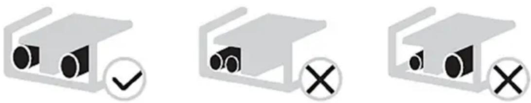
Handle the unit using the sling to the left and the handle to the right. Pull up both sides of the sling at the same time to prevent discinfection of the sling from the unit
While handling the unit keep both sides of the sling level. Keep your back straight
natural_image
Two workers carrying a large fan-shaped device (no text or symbols visible)After mounting the unit, remove the sling from the unit by pulling 1 side of the sling.

CAUTION
• To avoid injury, do not touch the air inlet and aluminum fins of the unit.
- Do not use the grips in the fan grills to avoid damage.
- The unit is top heavy! Prevent the unit from falling due to improper inclination during handling.
IMPORTANT INFORMATION FOR THE REFRIGERANT
Before installation
This product has the fluorinated gas, it is forbidden to release to air.
Refrigerant type: R32; Volume of GWP: 675.
GWP=Global Warming Potential
| Model | Factory charged refrigerant volume in the unit | |
| Refrigerant/kg | Tonnes CO2 equivalent | |
| 4kW | 1.50 | 1.02 |
| 6kW | 1.50 | 1.02 |
| 8kW | 1.65 | 1.11 |
| 10kW | 1.65 | 1.11 |
| Model | Factory charged refrigerant volume in the unit | |
| Refrigerant/kg | Tonnes CO2 equivalent | |
| 1-phase 12kW | 1.84 | 1.24 |
| 1-phase 14kW | 1.84 | 1.24 |
| 1-phase 16kW | 1.84 | 1.24 |
| 1-phase 12kW | 1.84 | 1.24 |
| 1-phase 14kW | 1.84 | 1.24 |
| 1-phase 16kW | 1.84 | 1.24 |

CAUTION
• Frequency of Refrigerant Leakage Checks
- Equipment that contains less than 3 kg of fluorinated greenhouse gases or hermetically sealed equipment, which is labelled accordingly and contains less than 6 kg of fluorinated greenhouse gases shall not be subject to leak checks.
- For unit that contains fluorinated greenhouse gases in quantities of 5 tonnes of CO2 equivalent or more, but of less than 50 tonnes of CO2 equivalent, at least every 12 months, or where a leakage detection system is installed, at least every 24 months.
- This air-conditioning unit is a hermetically sealed equipment that contains fluorinated greenhouse gases.
- Only certificated person is allowed to do installation, operation and maintenance.
INSTALLATION SITE

WARNING
- Be sure to adopt adequate measures to prevent the unit from being used as a shelter by small animals. Small animals making contact with electrical parts can cause malfunction, smoke or fire. Please instruct the customer to keep the area around the unit clean.
-
Select an installation site where the following condition sare satisfied and one that meets with your customer's approval.
-
Places that are well-ventilated.
- Places where the unit does not disturb next-door neighbors.
- Safe places which can bear the unit's weight and vibration and where the unit can be installed at an even level.
-
Places where there is no possibility of flammable gas or product leak.
-
The equipment is not intended for use in a potentially explosive atmosphere.
- Places where servicing space can be well ensured.
- Places where the units' piping and wiring lengths come within the allowable ranges.
- Places where water leaking from the unit cannot cause damage to the location (e.g. in case of a blocked drain pipe).
- Places where rain can be avoided as much as possible.
- Do not install the unit in places often used as a work space. In case of construction work (e.g. grinding etc.) where a lot of dust is created, the unit must be covered.
- Do not place any object or equipment on top of the unit (top plate)
- Do not climb, sit or stand on top of the unit.
- Be sure that sufficient precautions are taken in case of refrigerant leakage according to relevant local laws and regulations.
- Don't install the unit near the sea or where there is corrosion gas.
- When installing the unit in a place exposed to strong wind, pay special attention to the following:
- Strong winds of 5 m/sec or more blowing against the unit's air outlet causes a short circuit (suction of discharge air), and this may have the following consequences:
- Deterioration of the operational capacity.
- Frequent frost acceleration in heating operation.
- Disruption of operation due to rise of high pressure.
- Motor burnout.
- When a strong wind blows continuously on the front of the unit, the fan can start rotating very fast until it breaks.
In normal condition, refer to the figures below for installation of the unit
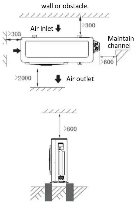
4/6/8/10/12/14/16 kW (unit: mm)
NOTE
- Make sure there is enough space to do the installation. Set the outlet side at a right angle to the direction of the wind.
- Prepare a water drainage channel around the foundation, to drain waste water from around the unit.
- If water does not easily drain from the unit, mount the unit on a foundation of concrete blocks, etc. (the height of the foundation should be about 100 mm .(in Fig:6-3)
- When installing the unit in a place frequently exposed to snow, pay special attention to elevate the foundation as high as possible.

NOTE
- If you install the unit on a building frame, please install a waterproof plate (field supply) (about 100mm, on the underside of the unit) in order to avoid drain water dripping. (See the picture in the right).
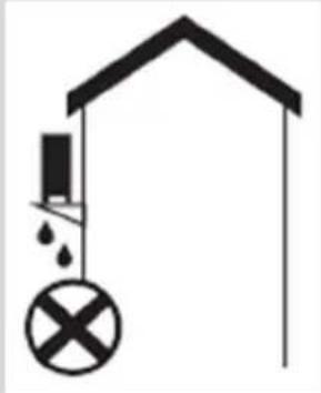
natural_image
Simple line drawing of a house with a hanging structure and a cross symbol (no text or labels)Selecting a location in cold climates
Refer to "Handling" in section „Before installation“

NOTE
When operating the unit in cold climates, be sure to follow the instructions described below.
- To prevent exposure to wind, install the unit with its suction side facing the wall.
- Never install the unit at a site where the suction side may be exposed directly to wind.
- To prevent exposure to wind, install a baffle plate on the air discharge side of the unit.
- In heavy snowfall areas, it is very important to select an installation site where the snow will not affect the unit. If lateral snowfall is possible, make sure that the heat exchanger coil is not affected by the snow (if necessary construct a lateral canopy).
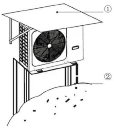
① Construct a large canopy.
② Construct a pedestal.
Install the unit high enough off the ground to prevent it from being buried in snow.
Prevent Sunshine
As the outdoor temperature is measured via the outdoor unit air thermistor, make sure to install the outdoor unit in the shade or a canopy should be constructed to avoid direct sunlight, so that it is not influenced by the sun's heat, otherwise protection may be possible to the unit.

WARNING
Uncovered scene, anti-snow shed must be installed:
(1) To prevent rain and snow from hitting the heat exchanger, resulting in poor heating capacity of the unit, after long time accumulation, the heat exchanger freezes;
(2) To prevent the outdoor unit air thermistor from being exposed to the sun, resulting in failure to boot;
(3) To prevent freezing rain.
INSTALLATION PRECAUTIONS
Dimensions
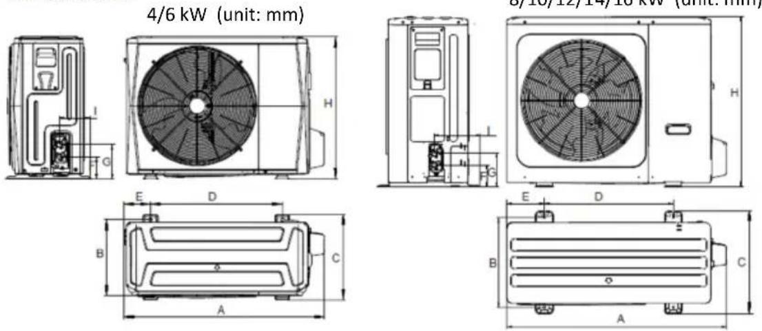
8/10/12/14/16 kW (unit: mm)
Fig 6-1
Fig 6-2
| Model | A | B | C | D | E | F | G | H | I |
| 4/6kW | 1008 | 375 | 426 | 663 | 134 | 110 | 170 | 712 | 160 |
| 8/10/12/14/16 kW | 1118 | 456 | 523 | 656 | 191 | 110 | 170 | 865 | 230 |
Installation requirements
Check the strength and level of the installation ground so that the unit may not cause any vibrations or noise during the operation.
In accordance with the foundation drawing in the figure, fix the unit securely by means of foundation bolts. (Prepare four sets each of 10 Expansion bolts, nuts and washers which are readily available in the market.)
Screw in the foundation bolts until their length is 20 mm from the foundation surface.
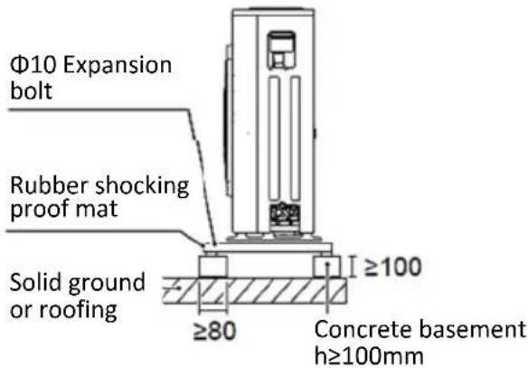
Fig 6-3
natural_image
Technical line drawing of a front-mounted air conditioning unit with fan blades and base plate (no text or symbols)Fig 6-4
Drain hole position
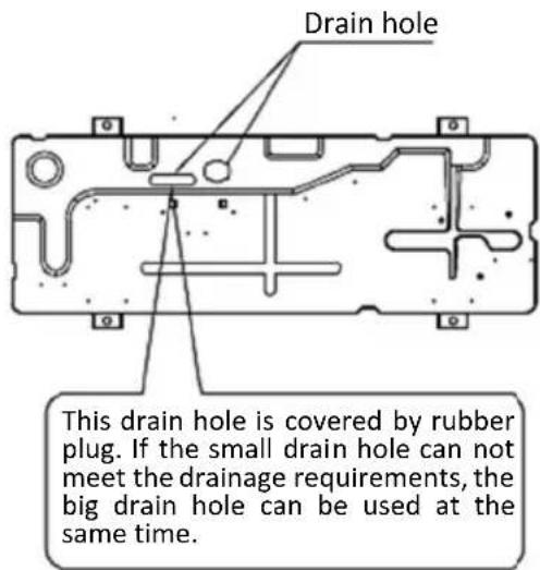
4/6 wW
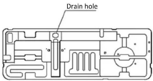
8/10/12/14/16 kW
Fig. 6-5

CAUTION
It's necessary to install an electrical heating belt if water can't drain out in cold weather even the big drain hole has opened.
It is suggested to site the unit with the base electric heater.
Installation space requirements
In case of stacked installation
1) In case obstacles exist in front of the outlet side
2) In case obstacles exist in front of the air inlet
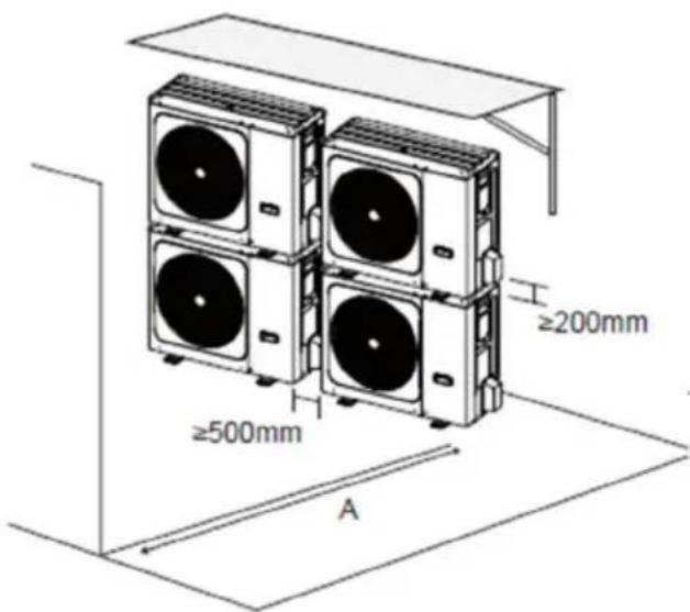
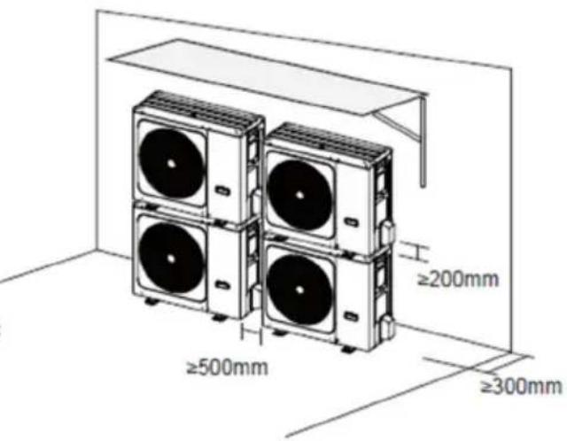
Fig. 6-6
| Unit | A(mm) |
| 4~16kW ≥2000 |

NOTE
It's necessary to install the water outlet connection pipe assembly if the unit is mounted on the top of each other, preventing condensate flow to the heat exchanger.
In case of multiple-row installation (for roof top use, etc.)
1) In case of installing one unit per row.
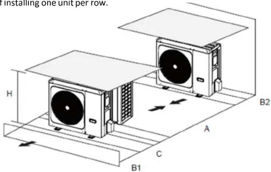
Fig. 6-7
| Unit | A(mm) | B1(mm) | B2(mm) | C(mm) |
| 4~16kW | ≥3000 ≥2000 | ≥150 ≥600 | ||
1) In case of installing multiple units in lateral connection per row.
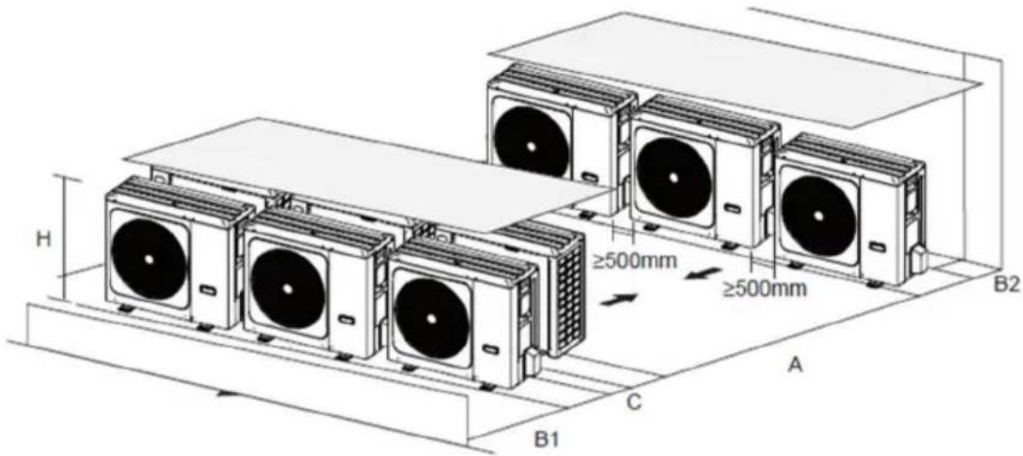
Fig. 6-8
| Unit | A(mm) | B1(mm) | B2(mm) | C(mm) |
| 4~16kW | ≥3000 ≥2000 | ≥300 ≥600 | ||
INSTALL THE CONNECTING PIPE
Check whether the difference in height between the indoor unit and outdoor unit, the length of refrigerant pipe, and the number of the bends meet the following requirements:
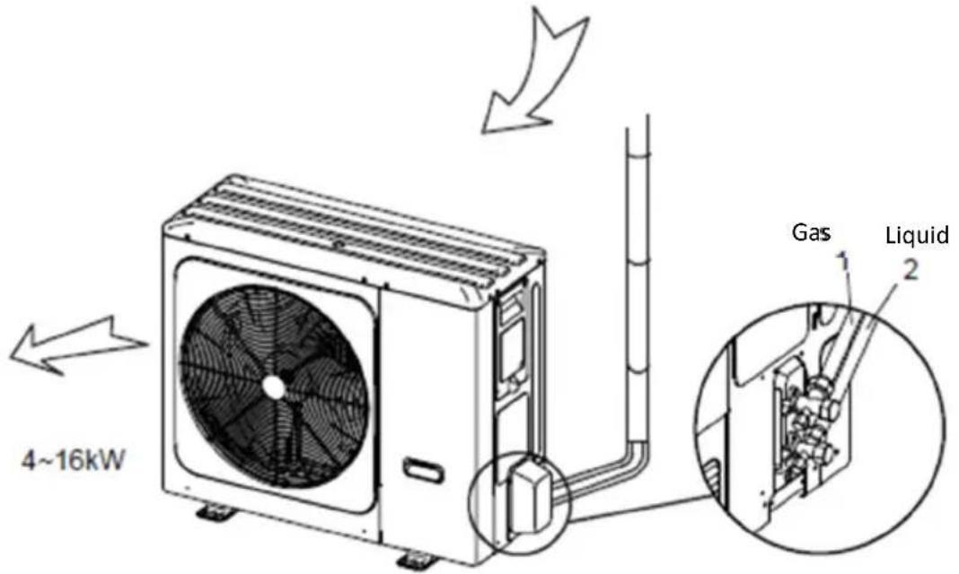
Fig. 7-1

CAUTION
- Please pay attention to avoid the components where it is connecting to the connecting pipes.
- To prevent the refrigerant piping from oxidizing inside when welding, it is necessary to charge nitrogen, or oxide will chock the circulation system.
- Back out pipe: Undersurface outlet pipe: the knock out should from inside to outside, and then piping and wiring through this. Pay attention to the piping, the fat connecting pipe should out from the largest hole, otherwise the pipes will be rubbed. Please do the moth proofing for the knocked out hole, to avoid the pest processing into and destroy the components. Please wipe off the piping support rubber blanket beside the inner outlet pipe cover of the machine while back side getting out pipes.
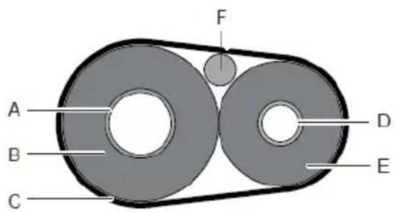
Leakage Detection
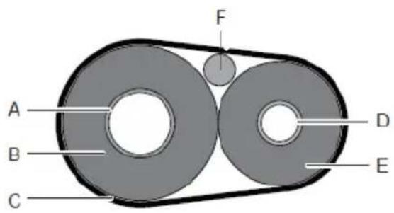
Use soap water or leakage detector to check every joint whether leak or not (Refer to Fig.7-2).
Note:
A is high pressure side stop valve
B is low pressure side stop valve
C and D is connecting pipes interface of indoor and outdoor units
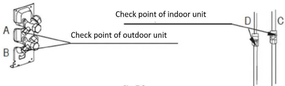
Fig. 7-2
Heat Insulation
Do the heat insulation to the pipes of gas side and liquid side separately. The temperature of the pipes of gas side and liquid side when cooling, for avoiding condensation please do the heat insulation fully.
1) The gas side pipe should use closed cell foamed insulation material, which the fire-retardant is B1 grade and the heat resistance over 120 °C.
2) When the external diameter of copper pipe≤Φ12.7mm, the thickness of the insulating layer at least more than 15mm; When the external diameter of copper pipe≥Φ15.9mm, the thickness of the insulating layer at least more than 20mm.
3) Please use attached heat-insulating materials do the heat insulation without clearance for the connecting parts of the indoor unit pipes.
Fig. 7-3
Connecting method
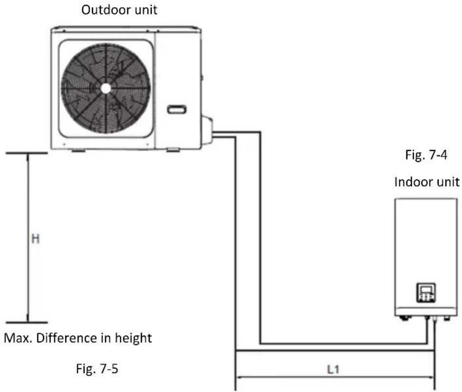

CAUTION
The largest level difference between indoor unit and outdoor unit should not exceed 20m (if the outdoor unit is above) or 15m (if the outdoor unit is below). Additionally: (i) If the outdoor unit is above and the level difference is greater than 20m, it is recommended that an oil return bend with dimensions as specified in Figure 7-4 is set every 5m in the gas pipe of the main pipe; and (ii) if the outdoor unit is below and the level difference is more than 15m, the liquid pipe of the main pipe should be increased one size.
1) Size of pipes of Gas side and Liquid side
| MODEL | Refrigerant | Gas side/Liquid side |
| 4/6kW | R32 | 15.9 / 6.35 |
| 8/10kW | R32 | 15.9 / 9.52 |
| 1-phase 12/14/16kW | R32 | 15.9 / 9.52 |
| 3-phase 12/14/16kW | R32 | 15.9 / 9.52 |
2) Connection method
| Gas side | Liquid side | |
| 4-16 kW outdoor unit | Flaring | Flaring |
| Indoor unit | Flaring | Flaring |
| MODELS | 4-16 kW |
| Max.piping length (H+L1) | 30m |
| Max difference in height (H) | 20m |
Remove Dirt or Water in the Pipes
1) Make sure there is no any dirt or water before connectiong the piping to the outdoor and indoor units.
2) Wash the pipes with high pressure nitrogen, never use refrigerant of outdoor unit.
Airtight Testing
Charge pressured nitrogen after connecting indoor/outdoor unit pipes to do airtight testing

CAUTION
Pressured nitrogen [4.3MPa (44kg/cm ^2 ) for R32] should be used in the airtight testing.
Tighten high/low pressure valves before charging pressured nitrogen. Charge pressure nitrogen from the connector on the pressure valves.
The airtight testing should never use any oxygen, flammable gas or poisonous gas.
Air Purge with Vacuum Pump
1) Using vacuum pump to do the vacuum, never using refrigerant to expel the air.
2) Vacuuming should be done from liquid side
Refrigerant Amount to be Added
Calculate the added refrigerant according to the diameter and the length of the liquid side pipe of the outdoor unit/indoor unit connection.
If the length of the liquid side pipe is less than 15 meters it is no need to add more refrigerant, so than calculating the added refrigerant the length of the liquid side pipe must subtract 15 meters
| Refrigerant to be added | MODEL | Total liquid pipe length L(m) | |
| ≤15m | >15m | ||
| Total additional refrigerant | 4 / 6 kW | 0g | (L-15)×20g |
| 8 /10/12/14/16 kW | 0g | (L-15)×38g | |
OUTDOOR UNIT WIRING

WARNING
A main switch or other means of disconnection, having a contact separation in all poles, must be incorporated in the fixed wiring in accordance with relevant local laws and regulations. Switch off the power supply before making any connections. Use only copper wires. Never squeeze bundled cables and make sure they do not come in contact with the piping and sharp edges. Make sure no external pressure is applied to the terminal connections. All field wiring and components must be installed by a licensed electrician and must comply with relevant local laws and regulations.
The field wiring must be carried out in accordance with the wiring diagram supplied with the unit and the instructions given below.
Be sure to use a dedicated power supply. Never use a power supply shared by another appliance.
Be sure to establish a ground. Do not ground the unit to a utility pipe, surge protector, or telephone ground. Incomplete grounding may cause electrical shock.
Be sure to install a ground fault circuit interrupter (30 mA). Failure to do so may cause electrical shock. Be sure to install the required fuses or circuit breakers.
Precautions on electrical wiring work
- Fix cables so that cables do not make contact with the pipes (especially on the high pressure side).
- Secure the electrical wiring with cable ties as shown in figure so that it does not come in contact with the piping, particularly on the high-pressure side.
• Make sure no external pressure is applied to the terminal connectors. - When installing the ground fault circuit interrupter make sure that it is compatible with the inverter (resistant to high frequency electrical noise) to avoid unnecessary opening of the ground fault circuit interrupter.

NOTE
The ground fault circuit interrupter must be a high-speed type breaker of 30 mA (<0.1s)
- This unit is equipped with an inverter. Installing a phase advancing capacitor not only will reduce the power factor improvement effect, but also may cause abnormal heating of the capacitor due to high-frequency waves. Never install a phase advancing capacitor as it could lead to an accident.
•
Precautions on wiring of power supply
- Use a round crimp-style terminal for connection to the power supply terminal board. In case it cannot be used due to unavoidable reasons, be sure to observe the following instructions.
- Do not connect different gauge wires to the same power supply terminal. (Loose connections may cause overheating.)
- When connecting wires of the same gauge, connect them according to the figure below.
natural_image
Three identical 3D-rendered mechanical components with checkmark and cross symbols, no text or labels present.- Use the correct screwdriver to tighten the terminal screws. Small screwdrivers can damage the screw head and prevent appropriate tightening.
• Over-tightening the terminal screws can damage the screws. - Attach a ground fault circuit interrupter and fuse to the power supply line.
- In wiring, make certain that prescribed wires are used, carry out complete connections, and fix the wires so that outside force cannot affect the terminals
Safety device requirement
- Select the wire diameters (minimum value) individually for each unit based on the table 8-1 and table 8-2, where the rated current in table 9-1 means MCA in table 9-2. In case the MCA exceeds 63A, the wire diameters should be selected according to the national wiring regulation.
- Select circuit breaker that having a contact separation in all poles not less than 3 mm providing full disconnection, where MFA is used to select the current circuit breakers and residual current operation breakers:
| Rated current of appliance:(A) | Nominal cross-sectional area ( mm^2 ) | |
| Flexible cords | Cable for fixed wiring | |
| ≤3 | 0.5 and 0.75 | 1 and 2.5 |
| >3 and ≤6 | 0.75 and 1 | 1 and 2.5 |
| >6 and ≤10 | 1 and 1.5 | 1 and 2.5 |
| >10 and ≤16 | 1.5 and 2.5 | 1.5 and 4 |
| >16 and ≤25 | 2.5 and 4 | 2.5 and 6 |
| >25 and ≤32 | 4 and 6 | 4 and 10 |
| >32 and ≤50 | 6 and 10 | 6 and 16 |
| >50 and ≤63 | 10 and 16 | 10 and 25 |
Fig. 8-1
| System | Outdoor Unit | Power Current | Compressor | Compressor | |||||||
| Voltage (V) | Hz | Min. (V) | Max. (V) | MCA (A) | TOCA (A) | MFA (A) | MSC (A) | RLA (A) | KW | FLA (A) | |
| 4kW | 220-240 | 50 | 198 | 264 | 12 | 18 | 25 | - | 11.50 | 0.10 | 0.50 |
| 6kW | 220-240 | 50 | 198 | 264 | 14 | 18 | 25 | - | 13.50 | 0.10 | 0.50 |
| 8kW | 220-240 | 50 | 198 | 264 | 16 | 19 | 25 | - | 14.50 | 0.17 | 1.50 |
| 10kW | 220-240 | 50 | 198 | 264 | 17 | 19 | 25 | - | 15.50 | 0.17 | 1.50 |
| 12kW | 220-240 | 50 | 198 | 264 | 25 | 30 | 35 | - | 23.50 0.17 | 1.50 | |
| 14kW | 220-240 | 50 | 198 | 264 | 26 | 30 | 35 | - | 24.50 0.17 | 1.50 | |
| 16kW | 220-240 | 50 | 198 | 264 | 27 | 30 | 35 | - | 25.50 0.17 | 1.50 | |
| 12kW 3-PH | 380-415 | 50 | 342 | 456 | 10 | 14 | 16 | - | 9.15 0.17 | 1.50 | |
| 14kW 3-PH | 380-415 | 50 | 342 | 456 | 11 | 14 | 16 | - | 10.15 | 0.17 | 1.50 |
| 16kW 3-PH | 380-415 | 50 | 342 | 456 | 12 | 14 | 16 | - | 11.15 | 0.17 | 1.50 |

NOTE
MCA : Max. Circuit Amps. (A)
TOCA : Total Over-current Amps. (A)
MFA : Max. Fuse Amps. (A)
MSC : Max. Fuse Amps. (A)
FLA : In nominal cooling or heating test condition, the input Amps of compressor where MAX. Hz can operate Rated Load Amps. (A);
KW : Rated Motor Output
FLA : Full Load Amps. (A)
Remove the switch box cover
| Unit (kW) | 4 kW | 6 kW | 8 kW | 10 kW | 12 kW | 14 kW | 16 kW | 12kW-3-PH | 14kW-3-PH | 16kW-3-PH |
| Maximum overcurrent protector (MOP) (A) | 18 A | 18 A | 19 A | 19 A | 30 A | 30 A | 30 A | 14 A | 14 A | 14 A |
| Wiring size ( mm^2 ) | 4.0 mm^2 | 4.0 mm^2 | 4.0 mm^2 | 4.0 mm^2 | 6.0 mm^2 | 6.0 mm^2 | 6.0 mm^2 | 2.5 mm^2 | 2.5 mm^2 | 2.5 mm^2 |
Stated values are maximum values (see electrical data for exact values).
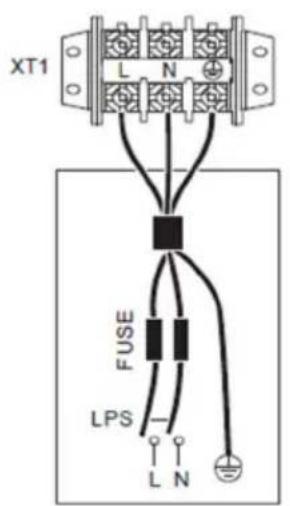
Outdoor Unit Power supply 1-phase
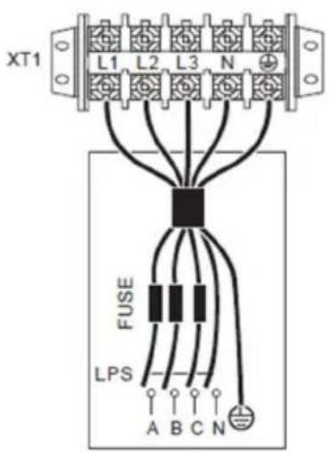
Outdoor Unit Power supply 3-phase
natural_image
Technical line drawing of a multi-chamber air conditioning unit with fan and cooling unit (no text or symbols)
NOTE
The ground fault circuit interrupter must be a high-speed type breaker of 30 mA (<0.1s). Please use 3-core shielded wire.
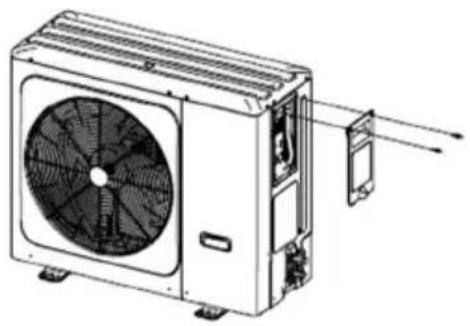
To finish the outdoor unit installation
| A | Gas pipe |
| B | Gas pipe insulation |
| C | Finishing tipe |
| D | Liquid pipe |
| E | Liquid pipe insulation |
| F | Interconnection cable |
OVERVIEW OF THE UNIT
Disassembling the unit
natural_image
Technical line drawing of a fan or vent assembly with no visible text or symbols4/6 kW
Door 1: To access to the compressor and electrical parts
natural_image
Technical line drawing of a dual-panel air conditioner unit with fan blades and vent, no text or symbols present8/10/12/14/16 kW
Door 1: To access to the compressor and electrical parts

WARNING
- Switch off all power — i.e. unit power supply and backup heater and domestic hot water tank power supply (if applicable) — before removing doors 1.
• Parts inside the unit may be hot.
Push the grill to the left until it stops, then pull its right edge, so you can remove the grill. You can also reverse the procedure. Be careful to avoid hand injury.
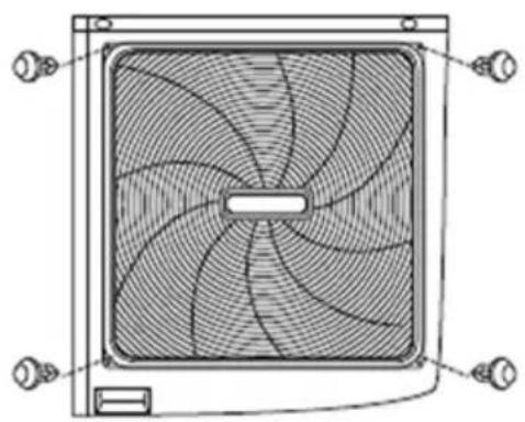
natural_image
Technical line drawing of a square fan with visible blades and mounting connectors (no text or symbols)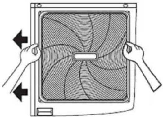
natural_image
Illustration of hands holding a fan blade with blades radiating outward (no text or symbols)Electronic control box
12/14/16kW 3-phase

NOTE
The picture is for reference only, please refer to the actual product.
4\~16kW 1-phase units
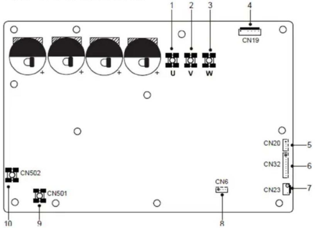
1) PCB A, 4-10 kW Inverter module
| Coding | Assembly unit | Coding | Assembly unit |
| 1 | Compressor connection port U | 6 | Reserved(CN302) |
| 2 | Compressor connection port V | 7 | Port for communication with PCB B(CN32) |
| 3 | Compressor connection port W | 8 | Input port N for rectifier bridge(CN502) |
| 4 | Output port for +12V/9V(CN20) | 9 | Input port L for rectifier bridge(CN501) |
| 5 | Port for fan(CN19) | / | / |
2) PCB A, 12-16 kW Inverter module
| Coding | Assembly unit | Coding | Assembly unit |
| 1 | Compressor connection port U | 6 | Port for communication with PCB B(CN32) |
| 2 | Compressor connection port V | 7 | Port for high pressure switch (CN23) |
| 3 | Compressor connection port W | 8 | Reserved(CN6)) |
| 4 | Port for fan(CN19) | 9 | Input port N for rectifier bridge (CN501) |
| 5 | Output port for +12V/9V(CN20) | 10 | Input port N for rectifier bridge (CN502) |
3) PCB B, 4-16 kW Main Control Board
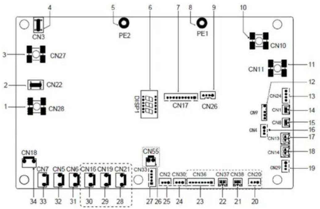
| Coding | Assembly unit | Coding | Assembly unit |
| 1 | Output port L to PCB A(CN28) | 18 | Port for low pressure switch (CN14) |
| 2 | Reserved(CN22) | 19 | Port for communication with hydro-box control board (CN29) |
| 3 | Output port N to PCB A(CN27) | 20 | Reserved(CN20) |
| 4 | Reserved(CN3) | 21 | Reserved(CN38) |
| 5 | Port for ground wire(PE2) | 22 | Reserved(CN37) |
| 6 | Digital display(DSP1) | 23 | Reserved(CN36) |
| 7 | Port for communication with PCB A(CN17) | 24 | Port for communication(reserved,CN30) |
| 8 | Port for ground wire(PE1) | 25 | Port for communication(reserved,CN2) |
| 9 | Reserved(CN26) | 26 | Reserved(CN55) |
| 10 | Input port for neutral wire(CN10) | 27 | Port for electrical expansion valve(CN33) |
| 11 | Input port for live wire(CN11) | 28 | Reserved(CN21) |
| 12 | Port for outdoor ambient temp. sensor and condenser temp.sensor(CN9) | 29 | Reserved(CN19) |
| 13 | Input port for +12V/9V(CN24) | 30 | Port for chassis electrical heating tape(CN16)(optional) |
| 14 | Port for sunction temp.sensor(CN1) | 31 | Port for 4-way valve(CN6) |
| 15 | Port for discharge temp.sensor(CN8) | 32 | Port for SV6 valve(CN5) |
| 16 | Port for pressure sensor(CN4) | 33 | Port for compressor eletric heating tape 1(CN7) |
| 17 | Port for high pressure switch (CN13) | 34 | Port for compressor eletric heating tape 2(CN18) |
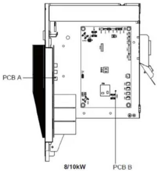
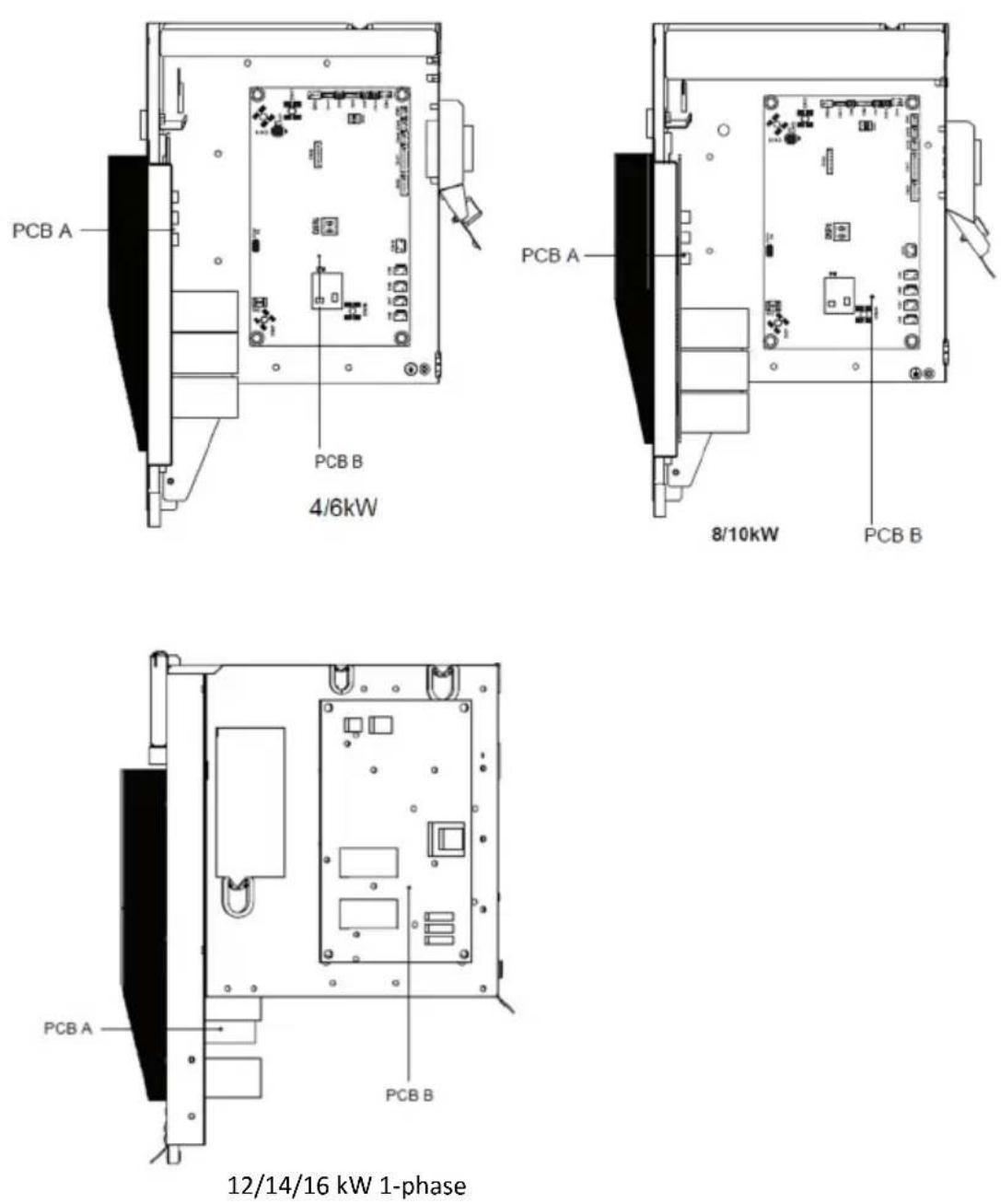
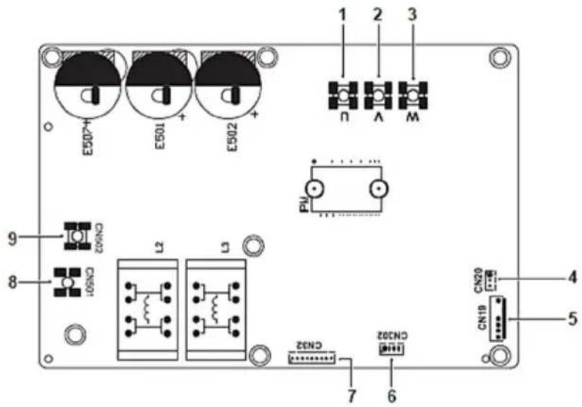
12\~16kW 1-phase units
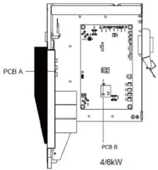
1) PCB A, Inverter module
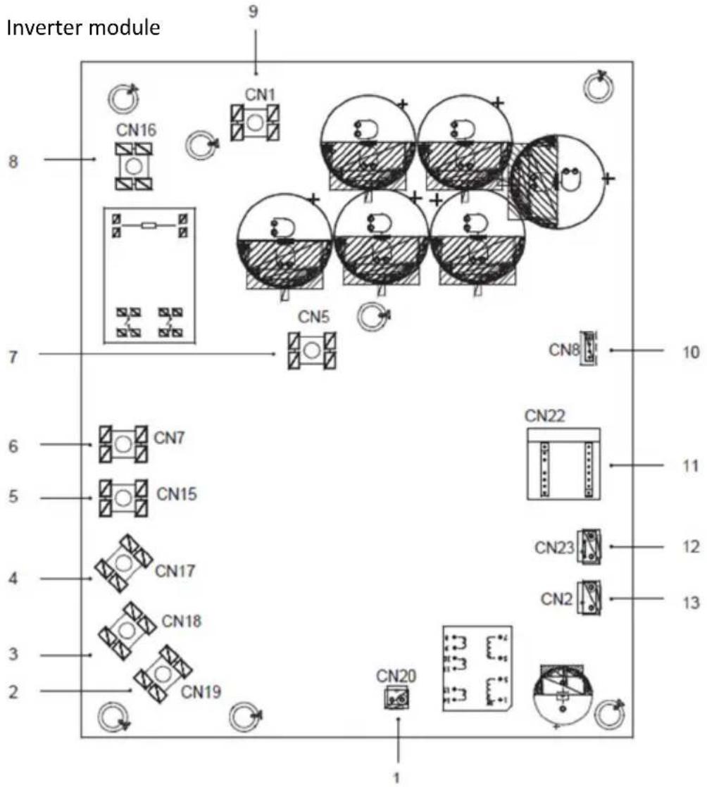
| Coding | Assembly unit | Coding | Assembly unit |
| 1 | Output port for +15V(CN20)) | 8 | Power Input port L1(CN16) |
| 2 | Compressor connection port W(CN19) | 9 | Input port P_in for IPM module(CN1) |
| 3 | Compressor connection port V(CN18) | 10 | Port for communication with PCB B (CN8) |
| 4 | Compressor connection port U(CN17) | 11 | PED board(CN22) |
| 5 | Power Input port L3(CN15) | 12 | Port for high pressure switch (CN23) |
| 6 | Power Input port L2(CN7) | 13 | Port for communication with PCB C(CN2) |
| 7 | Input port P_out for IPM module(CN5) |
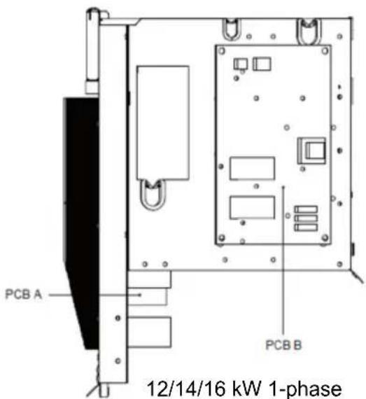
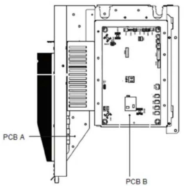
2)
PCB B, Main Control Board
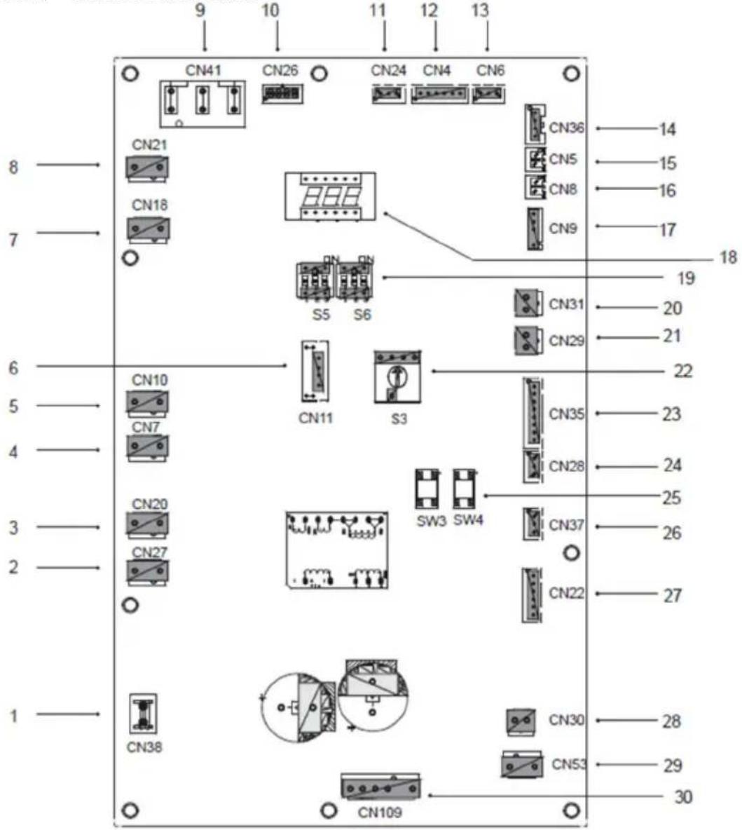
| Coding | Assembly unit | Coding | Assembly unit |
| 1 | Port for ground wire(CN38) | 16 | Port for temp.sensor Tp(CN8) |
| 2 | Port for 2-way valve 6(CN27) | 17 | Port for outdoor ambient temp. sensor and condenser temp.sensor(CN9) |
| 3 | Port for 2-way valve 5(CN20) | 18 | Digital display(DSP1) |
| 4 | Port for eletric heating tape2(CN7) | 19 | DIP switch(S5,S6) |
| 5 | Port for eletric heating tape1(CN10) | 20 | Port for low pressure switch(CN31) |
| 6 | Reserved(CN11) | 21 | Port for high pressure switch and quick check(CN29) |
| 7 | Port for 4-way valve(CN18) | 22 | Rotary dip switch(S3) |
| 8 | Reserved(CN21) | 23 | Port for temp.sensors(TW_out, TW_in, T1, T2,T2B )(CN35)(Reserved) |
| 9 | Power supply port from PCB C(CN41) | 24 | Port for communication XYE(CN28) |
| 10 | Port for communication with Power Meter(CN26) | 25 | Key for force cool&check(S3,S4) |
| 11 | Port for communication with hydro-box control board (CN24) | 26 | Port for communication H1H2E(CN37) |
| 12 | Port for communication with PCB C(CN4) | 27 | Port for electrical expansion valve(CN22) |
| 13 | Port for pressure sensor(CN6) | 28 | Port for fan 15VDC power supply(CN30) |
| 14 | Port for communication with PCB A(CN36) | 29 | Port for fan 310VDC power supply(CN53) |
| 15 | Port for temp.sensor Th(CN5) | 30 | Port for fan(CN109) |
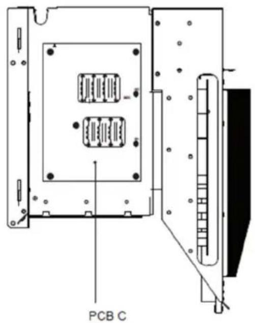
3)
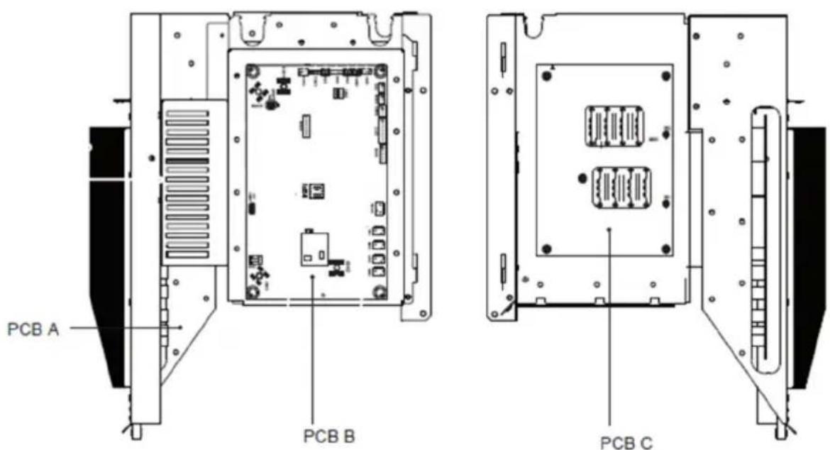
PCB C 3-phase 12/14/16kW, Filter Board
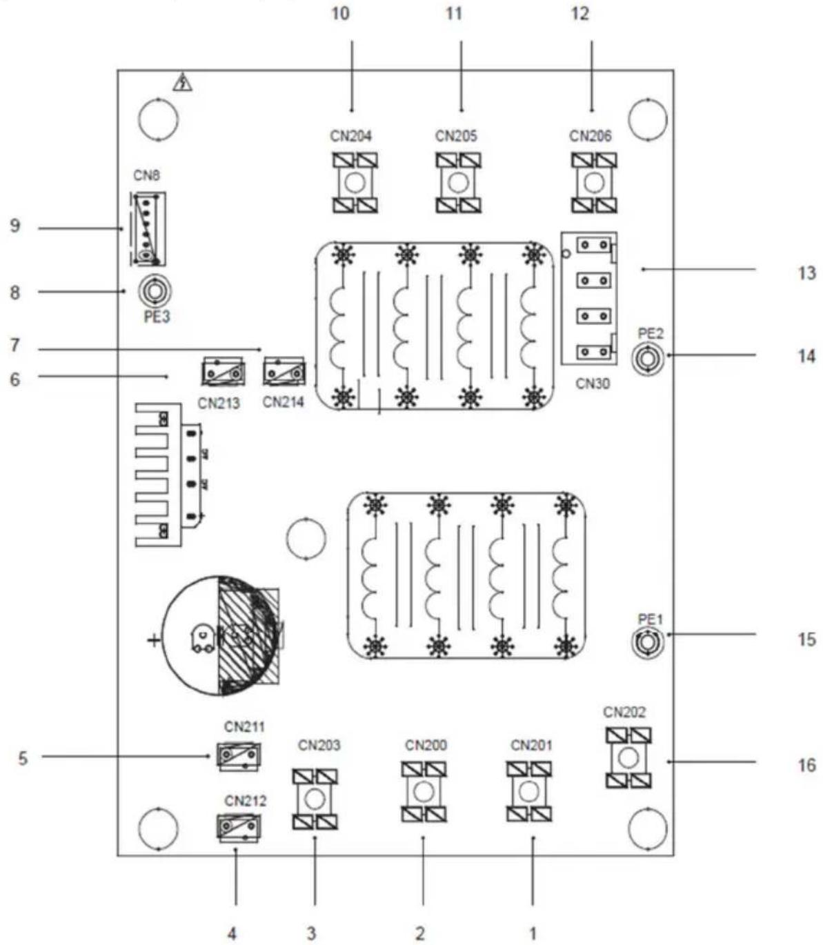
| Coding | Assembly unit | Coding | Assembly unit |
| 1 | Power supply L2(CN201) | 9 | Port for communication with PCB B (CN8) |
| 2 | Power supply L3(CN200) | 10 | Power filtering L3(L3') |
| 3 | Power supply N(CN203) | 11 | Power filtering L2(L2') |
| 4 | Power supply port of 310VDC(CN212) | 12 | Power filtering L1(L1') |
| 5 | Reserved(CN211) | 13 | Power supply port for main control board(CN30) |
| 6 | Port for FAN Reactor(CN213) | 14 | Port for ground wire(PE2) |
| 7 | Power supply port for Inverter module(CN214) | 15 | Port for ground wire(PE1) |
| 8 | Ground wire(PE3) | 16 | Power supply L1(L1) |
TEST RUNNING
Operate according to "key points for test running" on the electric control box cover.

CAUTION
- Test running can not start until the outdoor unit has been connected to the power for 12 hours.
- Test running can not start until all the valves are affirmed open.
PRECAUTIONS ON REFRIGERANT LEAKAGE
When the refrigerant charge in appliance is more than 1.842kg, following requirements should be complied with.
Requirements for charge limits in unventilated areas:
The maximum refrigerant charge in appliance shall be in accordance with the following:
$$ m _ {\max} = 2. 5 \times (\mathrm{LFL}) ^ {5 / 4} \times 1. 8 \times (\mathrm{A}) ^ {1 / 2} $$
or the required minimum floor area Amin to install an appliance with refrigerant charge mc shall be in accordance with following:
$$ A _ {\min} = \left(m _ {c} / (2. 5 \times (\text { LFL }) ^ {5 / 4} \times 1. 8)\right) ^ {2} $$
where
m_max is the allowable maximumm charge in a room, in kg
A is the room area, in m^2
A_min is the required minimum room area, in m^2
m_c is the refrigerant charge in appliance, in kg
LFL is the lower flammable limit in kg/m ^3 , the value is 0.306 for R32 refrigerant
- Install mechanical ventilator to reduce the refrigerant thickness, under critical level. (ventilate regularly).
- Install leak alarm facility related to mechanical ventilator if you can not regularly ventilate.
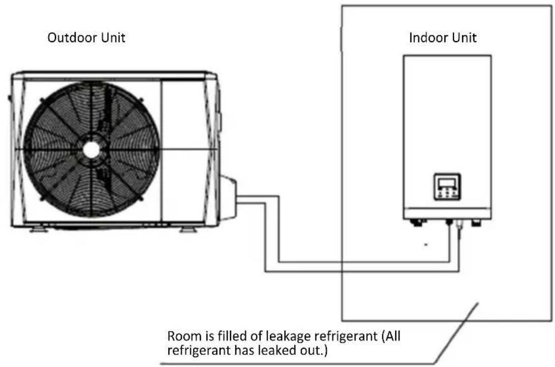
4/6kW
Fig 11-1
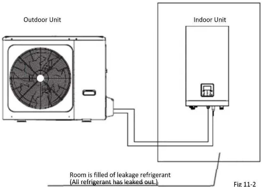
8/10/12/14/16 kW
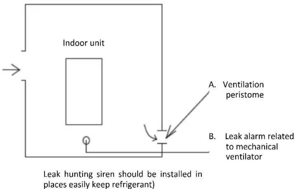
Fig 11-3
TURN OVER TO CUSTOMER
The owner's manual of indoor unit and owner's manual of outdoor unit must be turned over to the customer. Explain the contents in the owner's manual to the customers in details.

WARNING
- Ask your dealer for installation of the heat pump. Incomplete installation performed by yourself may result in a water leakage, electric shock, and fire.
- Ask your dealer for improvement, repair, and maintenance.
- Incomplete improvement, repair, and maintenance may result in a water leakage, electric shock, and fire.
- In order to avoid electric shock, fire or injury, or if you detect any abnormality such as smell of fire, turn off the power supply and call your dealer for instructions.
- Never let the indoor unit or the remote controller get wet. It may cause an electric shock or a fire.
- Never press the button of the remote controller with a hard, pointed object. The remote controller may be damaged.
- Never replace a fuse with that of wrong rated current or other wires when a fuse blows out. Use of wire or copper wire may cause the unit to break down or cause a fire.
- It is not good for your health to expose your body to the air flow for a long time.
- Do notinsert fingers, rods or other objects into the air inlet or outlet. When the fan is rotating at high speed, it will cause injury.
- Never use a flammable spray such as hair spray, lacqueror paint near the unit. It may cause a fire.
- Never put any objects into the air inlet or outlet. Objects touching the fan at high speed can be dangerous.
- Do not dispose this product as unsorted municipal waste. Collection of such waste separately for special treatment is necessary.
Do not dispose of electrical appliances as unsorted municipal waste, use separate collection facilities. Contact you local government for information regarding the connection systems available.
- If electrical appliances are disposed of in landfills or dumps, hazardous substances can leak into the groundeater and get into the food chain, damaging your health and well-being.
- To prevent refrigerant leak, contact your dealer.
- When the system is installed and runs in a small room, it is required to keep the concentration of the refrigerant, if by any chance coming out, below the limit. Otherwise, oxygen in the room may be affected, resulting in a serious accident.
- The refrigerant in the heat pump is safe and normally does not leak. If the refrigerant leaks in the room, contact with a fire of a burner, a heater or a cooker may result in a harmful gas
- Turn off any combustible heating devices, ventilate the room, and contact the dealer where you purchased the unit. Do not use the heat pump until a service person confirms that the portion where the refrigerant leaks is repaired.

CAUTION
- Do not use the heat pump for other purposes.
- In order to avoid any quality deterioration, do not use the unit for cooling precision instruments, food, plants, animals or works of art.
- Before cleaning, be sure to stop the operation, turn the breaker off or pull out the supply cord.
- Otherwise, an electric shock and injury may result.
- In order to avoid electric shock or fire, make sure that an earth leak detector is installed.
- Be sure the heat pump is grounded.
- In order to avoid electric shock, make sure that the unit is grounded and that the earth wire is not connected to gas or water pipe, lightning conductor or telephone earth wire.
- In order to avoid injury, do not remove the fan guard of the outdoor unit.
- Do not operate the heat pump with a wet hand.
- An electric shock may happen.
- Do not touch the heat exchanger fins.
• These fins are sharp and could result in cutting injuries. - Do not place items which might be damaged by moisture under the indoor unit.
- Condensation may form if the humidity is above 80%, the drain outlet is blocked or the filter is polluted.
-
Aftera long use, check the unit stand and fitting for damage.
-
If damaged, the unit may fall and result in injury.
- To avoid oxygen deficiency, ventilate the room sufficiently if equipment with burner is used together with the heat pump.
- Arrange the drain hose to ensure smooth drainage. Incomplete drainage may cause wetting of the building, furniture etc.
- Never touch the internal parts of the controller.
- Do not remove the front panel. Some parts inside are dangerous to touch, and a machine trouble may happen.
- Never do the maintenances work by yourself.
- Please contact your local dealer to do the maintenances work.
- Never expose little children, plants or animals directly to the air flow.
- Adverse influence to little children, animals and plants may result.
- Do not allow a child to mount on the outdoor unit or avoid placing any object on it.
- Falling or tumbling may result in injury.
- Do not operate the heat pump when using a room fumigation - type insecticide.
- Failure to observe could cause the chemicals to become deposited in the unit, which could endanger the health of those who are hypersensitive to chemicals.
- Do not place appliances which produce open fire in places exposed to the air flow from the unit or under the indoor unit.
- It may cause incomplete combuston
or deformation of the unit due to the heat.
- Do not install the heat pump at any place where flammable gas may leak out.
- If the gas leaks out and stays around the heat pump, a fire may break out.
- The appliance is not intended for use by young children or infirm persons without supervision.
- Young children should be supervised to ensure that they do not play with the appliance.
- The outdoor unit window-shades should be periodic cleaning in case of being jammed.
- This window-shapes is heat dissipation outlet of components, if being jammed will cause the components shorten their service life spans because of overheated for a long time.
- The temperature of refrigerant circuit will be high, please keep the interconnection cable away from the copper tube.
Protection Equipment
This Protection Equipment will enable the Heat Pump to stop when the Heat Pump is to be directed running compulsively.
The protection equipment may be activated in following conditions:
Cooling Operation
- The air inlet or air outlet of outdoor unit is blocked.
- Strong wind is Continuously blowing to the air outlet of the outdoor unit.
Heating Operation
- Too much rubbish adhere to the filter in the water system
- The air outlet of indoor unit is choked
- Mishandling in operation: If mishandling happens because of lighting or mobile wireless, please shut off the manual power switch, and turn on again, then push the ON/OFF button

NOTE
When the protection equipment starts, please shut down the manual power switch, and restart operation after problem is solved.
About Power Cut
- If power is cut during operation, stop all the operation immediately
- Power comes again. If the auto-restant function is set on, then the unit will auto-restart.
Heating capacity
- The heating operation is a heat-pump process that heat will be absorbed from outdoor air and released to indoor water. Once the outdoor temperature is decreased, heating capacity decreased corredpindingly.
- Other heating equipment is suggested to be used together when outdoor temperature is too low.
- In some extreme cold upland that buy the indoor unit equipped with electrical heater will obtain better performance.( Refer to indoor unit owner's manual for details)

NOTE
The motor in outdoor Unit will continue running for 60 seconds for to remove residual heat when the outdoor Unit receiving OFF command during heating operation.
If the heat pump malfunction occurs because of disturb, please reconnect the heat pump to power, then turn on it again.
Compressor protection feature
- A protection feature prevents the heat pump from being activated for approximately several minutes when it restarts immediately after operation.
Cooling and heating operation
- The the indoor unit in the same system can not run cooling and heating at the same time.
- If the Heat Pump Administrator has set running mode, then the heat pump can not run on modes other than the presetted. Standby or No Priority will be displayed in the Control Panel.
Features of heating operation
- Water will not become hot immediately at the beginning of the heating operation, 3\~5 minutes ago (depends on the indoor and outdoor temperature), until the indoor heat exchanger become hot, then becomes hot.
- During operation, the fan motor in the outdoor unit may stop running under high temperature.
Defrost in the heating operation
- During heating operation, outdoor unit sometimes will frost. To increase efficiency, the unit will start defrosting automatically (about 2\~10 minutes), and then water will be drained out from outdoor unit.
- During defrosting, the fan motors in the outdoor unit will stop running.
Error codes
When a safety device is activated, an error code will be displayed on the user interface.
A list of all errors and corrective actions can be found in the table below.
Reset the safety by turning the unit OFF and back ON.
In case this procedure for resetting the safety is not successful, contact your local dealer.
| ERROR CODE | MALFUNCTION OR PROTECTION | FAILURE CAUSE AND CORRECTIVE ACTION |
| EI | Phase loss or neutral wire and live wire are connected reversely(only for three phase unit). | 1. Check the power supply cables should be conneted stable, aviod phase loss.2. Check whether the sequence of neutral wire and live wire are connected reversely. |
| ES | The condenser outlet refrigerant temperature sensor (T3)error. | 1. The T3 sensor connector is loosen. Reconnect it.2. The T3 sensor connector is wet or there is water in. remove the water, make the connector dry.Add waterproof adhesive3. The T3 sensor failure, change a new sensor. |
| ES | The ambient temperature sensor (T4) error. | 1. The T4 sensor connector is loosen. Reconnect it.2. The T4 sensor connector is wet or there is water in. remove the water, make the connector dry.Add waterproof adhesive3. The T4 sensor failure, change a new sensor. |
| ES | Suction temperature sensor(Th) error | 1. The Th sensor connector is loosen. Re connect it.2. The Th sensor connector is wet or there is water in. remove the water, make the connector dry. Add waterproof adhesive3. The Th sensor failure, change a new sensor. |
| ER | Discharge temperature sensor(Tp) error | 1. The Tp sensor connector is loosen. Re connect it.2. The Tp sensor connector is wet or there is water in. remove the water, make the connector dry. Add waterproof adhesive3. The Tp sensor failure, change a new sensor. |
| H0 | Communication fault between indoor unit and outdoor unit | 1. wire doesn’t connect between main control board PCB B and main control board of hydraulic module. connect the wire.2. Communication wire sequence is not right. Reconnect the wire in the right sequence.3. Whether there is a high magnetic field or high power interfere, such as lifts, large power transformers, etc.. To add a barrier to protect the unit or to move the unit to the other place. |
| H1 | Communication error between inverter module PCB A and main control board PCB B | 1. Whether there is power connected to the PCB and driven board. Check the PCB indicator light is on or off. If Light is off, reconnect the power supply wire.2. if light is on, check the wire connection between the main PCB and driven PCB, if the wire loosen or broken, reconnect the wire or change a new wire.3. Replace a new main PCB and driven board in turn. |
| H4 | Three times P6 protect | The sum of the number of times L0 and L1 appear in an hour equals three.See L0 and L1 for fault handling methods |
| H5 | The DC fan failure | 1.Strong wind or typhoon below toward to the fan, to make the fan running in the opposite direction. Change the unit direction or make shelter to avoid typhoon below to the fan.2.fan motor is broken, change a new fan motor. |
| H7 | Main circuit voltage failure | 1. Whether the power supply input is in the available range.2. Power off and power on for several times rapidly in short time. Remain the unit power off for more than 3 minutes than power on.3. the circuit defect part of Main control board is defective. Replace a new Main PCB. |
| H8 | Pressure sensor failure | 1. Pressure sensor connector is loosen, reconnect it.2. Pressure sensor failure. change a new sensor. |
| HF | The main control board PCB B EEprom failure | 1. The EEprom parameter is error, rewrite the EEprom data.2. EEprom chip part is broken, change a new EEprom chip part.3. Main PCB is broken, change a new PCB. |
| HH | H6 displayed 10 times in 2 hours | Refer to H6 |
| HP | Low pressure protection Pe<0.6) occurred 3 times in an hour | Refer to PO |
| PO | Low pressure protection | 1. System is lack of refrigerant volume. Charge the refrigerant in right volume.2. When at heating mode or DHW mode, the outdoor heating exchanger is dirty or something is block on the surface. Clean the outdoor heating exchanger or remove the obstruction.3. The water flow is too low in cooling mode.increase the water flow.4. Electrical expansion valve locked or winding connector is loosen. Tap-tap the valve body and plug in/ plug off the connector for several times to make sure the valve is working correctly. |
| PI | High pressure switch protection | Heating mode, DHW mode:1. The water flow is low; water temp is high, whether there is air in the water system. Release the air.2. Water pressure is lower than 0.1Mpa, charge the water to let the pressure in the range of 0.15~0.2Mpa.3. Over charge the refrigerant volume. Recharge the refrigerant in right volume.4. Electrical expansion valve locked or winding connector is loosen. Tap-tap the valve body and plug in/ plug off the connector for several times to make sure the valve is working correctly. And install the winding in the right location DHW mode: Water tank heat exchanger is smallerCooling mode:1. Heat exchanger cover is not removed. Remove it.2. Heat exchanger is dirty or something is block on the surface. Clean the heat exchanger or remove the obstruction |
| P3 | Compressor overcurrent protection | 1. The same reason to P1.2. Power supply voltage of the unit is low, increase the power voltage to the required range |
| P4 | High discharge temperature protection | 1. The same reason to P1.2. TW_out temp.sensor is loosen Reconnect it.3. T1 temp.sensor is loosen. Reconnect it.4. T5 temp.sensor is loosen. Reconnect it |
| P9 | DC fan motor protect | Contact your local dealer |
| Pd | High temperature protection of refrigerant outlet temp of condenser | 1. Heat exchanger cover is not removed. Remove it.2. Heat exchanger is dirty or something is block on the surface. Clean the heat exchanger or remove the obstruction.3. There is no enough space around the unit for heat exchanging.4. Fan motor is broken, replace a new one |
| C7 | Transducer module temperature too high protect | 1. Power supply voltage of the unit is low, increase the power voltage to the required range.2. The space between the units is too narrow for heat exchange. Increase the space between the units.3. Heat exchanger is dirty or something is block on the surface. Clean the heat exchanger or remove the obstruction.4. Fan is not running. Fan motor or fan is broken, Change a new fan or fan motor.5. Water flow rate is low, there is air in system, or pump head is not enough. Release the air and reselect the pump.6. Water outlet temp.sensor is loosen or broken, reconnect it or change a new one. |
| F1 | DC generatrix voltage is too low | 1. Check the power supply.2. If the power supply is OK, and check if LED light is OK, check the voltage PN, if it is 380V, the problem usually comes from the main board. And if the light is OFF, disconnect the power, check the IGBT, check those dioxides, if the voltage is not correct, the inverter board is damaged, change it.3. And if those IGBT are OK, which means the inverter board is OK, power form rectifier bridge is not correct, check the bridge. (Same method as IGBT, disconnect the power, check those dioxides are damaged or not).4. Usually if F1 exist when compressor start, the possible reason is main board. If F1 exist when fan start, it may be because of inverter board |
| 6H | PED PCB failure | 1. After 5 minutes of power-off interval, power on again and observe whether it can be recovered;2. If it can't be restored, replace PED safety plate, power on again, and observe whether it can be restored;3. If it can not be recovered, the IPM module board should be replaced. |
| ERROR CODE | MALFUNCTION OR PROTECTION | FAILURE CAUSE AND CORRECTIVE ACTION | |
| P6 | L0 | Module protection | 1. Check the Heat pump system pressure;2. Check the phase resistance of compressor;3. Check the U、V、W power line connection sequence between the inverter board and the compressor;4. Check the L1、L2、L3 power line connection between the inverter board and the Filter board;5. Check the inverter board. |
| L1 | DC generatrix low voltage protection | ||
| L2 | DC generatrix high voltage protection | ||
| L4 | MCE malfunction | ||
| L5 | Zero speed protection | ||
| L8 | Speed difference >15Hz protection between the front and the back clock | ||
| L9 | Speed difference >15Hz protection between the real and the setting speed |
TECHNICAL SPECIFICATIONS
| Model (Capacity mark) | 4 kW | 6 kW | 8 kW | 10 kW |
| Power supply | 220-240V~ 50Hz | |||
| Rated power input | 2200W | 2600W | 3300W | 3600W |
| Rated current | 10.5A | 12.0A | 14.5A | 16.0A |
| Nominal capacity | Refer to the technical data | |||
| Dimensions (W×H×D)[mm] | 1008*712*426 1118*865*523 | |||
| Packing (W×H×D)[mm] | 1065*810*485 1190*970*560 | |||
| Fan motor | DC motor / Horizontal | |||
| Compressor | DC inverter dual rotary | |||
| Heat exchanger | Fin-coil | |||
| Refrigerant | ||||
| Type | R32 | |||
| Quantity | 1500 g | 1650g | ||
| Weight | ||||
| Net weight | 60kg 78.5kg | |||
| Gross weight | 65.5kg 92kg | |||
| Connections | ||||
| Gas side | φ15.9 | φ15.9 | ||
| Liquid side | φ6.35 | φ9.52 | ||
| Drain connection | DN32 | |||
| Max. piping length | 30m | |||
| Max. difference in height when outdoor unit is upside | 20m | |||
| Refrigerant to be added | 20g/m 38g/m | |||
| Operation ambient temperature range | ||||
| Heating mode | -25~+35°C | |||
| Cooling mode | -5~+43°C | |||
| Domestic hot water mode | -25~+43°C | |||
| Model (Capacity mark) | 12 kW | 14 kW | 16 kW | 12 kW3-phase | 14 kW3-phase | 16 kW3-phase |
| Power supply | 220-240V~ 50Hz | 380-415V 3N~ 50Hz | ||||
| Rated power input | 5400W | 5700W | 6100W | 5400W | 5700W | 6100W |
| Rated current | 14.5A | 25.0A | 26.0A | 9.0A | 10.0A | 11.0A |
| Nominal capacity | Refer to the technical data | |||||
| Dimensions(W×H×D)[mm] | 1118*865*523 1118*865*523 | |||||
| Packing(W×H×D)[mm] | 1190*970*560 1190*970*560 | |||||
| Fan motor | DC motor / Horizontal | |||||
| Compressor | DC inverter dual rotary | |||||
| Heat exchanger | Fin-coil | |||||
| Refrigerant | ||||||
| Type | R32 | |||||
| Quantity | 1840g 1840g | |||||
| Weight | ||||||
| Net weight | 100kg 116kg | |||||
| Gross weight | 113.5kg 129.5kg | |||||
| Connections | ||||||
| Gas side | 15.9 | 15.9 | ||||
| Liquid side | 9.52 | 9.52 | ||||
| Drain connection | DN32 | |||||
| Max. piping length | 30m | |||||
| Max. difference in height when outdoor unit is upside | 20m | |||||
| Refrigerant to be added | 38g/m | |||||
| Operation ambient temperature range | ||||||
| Heating mode | -25~+35°C | |||||
| Cooling mode | -5~+43°C | |||||
| Domestic hot water mode | -25~+43°C | |||||
INFORMATION SERVICING
1) Checks to the area
Prior to beginning work on systems containing flammable refrigerants, safety checks are necessary to ensure that the risk of ignition is minimised. For repair to the refrigerating system, the following precautions shall be complied with prior to conducting work on the system.
2) Work procedure
Works shall be undertaken under a controlled procedure so as to minimise the risk of a flammable gas or vapour being present while the work is being performed.
3) General work area
All maintenance staff and others working in the local area shall be instructed on the nature of work being carried out. work in confined sapces shall be avoided. The area around the work space shall be sectioned off. Ensure that the conditions within the area have been made safe by control of flammable material.
4) Checking for presence of refrigerant
The area shall be checked with an appropriate refrigerant detector prior to and during work, to ensure the technician is aware of potentially flammable atmospheres. Ensure that the leak detection equipment being used is suitable for use with flammable refrigerants, i.e. no sparking, adequately sealed or intrinsically safe.
5) Presence of fire extinguisher
If any hot work is to be conducted on the refrigeration equipment or any associated parts, appropriate fire extinguishing equipment shall be available to hand. Have a dry power or CO2 fire extinguisher adjacent to the charging area.
6) No ignition sources
No person carrying out work in relation to a refrigeration system which involves exposing any pipe work that contains or has contained flammable refrigerant shall use any sources of ignition in such a manner that it may lead to the risk of fire or explosion. All possible ignition sources, including cigarette smoking, should be kept sufficiently far away from the site of installation, repairing, removing and disposal, during which flammable refrigerant can possibly be released to the surrounding space. Prior to work taking place, the area around the equipment is to be surveyed to make sure that there are no flammable hazards or ignition risks. NO SMOKING signs shall be displayed.
7) Ventilated area
Ensure that the area is in the open or that it it adequately ventilated before breaking into the system or conducting any hot work. A degree of ventilation shall continue during the period that the work is carried out. The ventilation should safely disperse any released refrigerant and preferably expel it externally into the atmosphere.
8) Checks to the refrigeration equipment
Where electrical components are being changed, they shall be fit for the purpose and to the correct specification. At all times the manufacturer's maintenance and service guidelines shall be followed. If in doubt consult the manufacturer's technical department for assistance. The following checks shall be applied to installations using flammable refrigerants:
The charge size is in accordance with the room size within which the refrigerant containing parts are installed; The ventilation machinery and outlets are operating adequately and are not obstructed;
If an indirect refrigerating circuit is being used, the secondary circuits shall be checked for the presence of refrigerant; marking to the equipment continues to be visible and legible.
Marking and signs that are illegible shall be corrected;
Refrigeration pipe or components are installed in a position where they are unlikely to be exposed to any substance which may corrode refrigerant containing components, unless the components are constructed of materials which are inherently resistant to being corroded or are suitably protected against being so corroded.
9) Checks to electrical devices
Repair and maintenance to electrical components shall include initial safety checks and component inspection procedures. If a fault exists that could compromise safety, then no electrical supply shall be connected to the circuit until it is satisfactorily dealt with. If the fault cannot be corrected immediately but it is necessary to continue operation, and adequate temporary solution shall be used. This shall be reported to the owner of the equipment so all parties are advised.
Initial safety checks shall include:
That capacitors are discharged: this shall be done in a safe manner to avoid possibility of sparking;
That there no live electrical components and wiring are exposed while charging, recovering or purging the system; That there is continuity of earth bonding.
10) Repairs to sealed components
a) During repairs to sealed components, all electrical supplies shall be disconnected from the equipment being worked upon prior to any removal of sealed covers, etc. If it is absolutely necessary to have an electrical supply to equipment during servicing, then a permanently operating form of leak detection shall be located at the most critical point to warn of a potentially hazardous situation.
b) articular attention shall be paid to the following to ensure that by working on electrical components, the casing is not altered in such a way that the level of protection is affected. This shall include damage to cables, excessive number of connections, terminals not made to original specification, damage to seals, incorrect fitting of glands, etc.
NOTE
The use of silicon sealant may inhibit the effectiveness of some types of leak detection equipment. Instrinsically safe components do not have to be isolated prior to working on them.
11) Repair to intrinsically safe components
Do not apply any permanent inductive or capacitance loads to the circuit without ensuring that this will not exceed the permissible voltage and current permitted for the equipment in use. Intrinsically safe components are the only types that can be worked on while live in the presence of a flammable atmosphere. The test apparatus shall be at the correct rating. Replace components only with parts specified by the manufacturer. Other parts may result in the ignition of refrigerant in the atmosphere from a leak.
12) Cabling
Check that cabling will not be subject to wear, corrosion, excessive pressure, vibration, sharp edges or any other adverse environmental effects. The check shall also take into account the effects of aging or continual vibration from sources such as compressors or fans.
13) Detection of flammable refrigerants
Under no circumstances shall potential sources of ignition be used in the searching for or detection of refrigerant leaks. A halide torch (or any other detector using a naked flame) shall not be used.
14) Leak detection methods
The following leak detection methods are deemed acceptable for systems containing flammable refrigerants. Electronic leak detectors shall be used to detect flammable refrigerants, but the sensitivity may not be adequate, or may need recalibration.(Detection equipment shall be calibrated in a refrigerant-free area.) Ensure that the detector is not a potential source of ignition and is suitable for the refrigerant. Leak detection equipment shall be set at a percentage of the LFL of the refrigerant and shall be calibrated to the refrigerant employed and the appropriate percentage of gas (25% maximum) is confirmed. Leak detection fluids are suitable for use with most refrigerants but the use of detergents containing chlorine shall be avoided as the chlorine may react with the refrigerant and corrode the copper pipework. If a leak is suspected ,all naked flames shall be removed or extinguished. If a leakage of refrigernat is found which requires brazing, all of the refrigerant shall be recovered from the system, or isolated(by means of shut off valves) in a part of the system remote from the leak . Oxygen free nitrogen(OFN) shall then be purged through the system both before and during the brazing process.
15) Removal and evacuation
When breaking into the refrigerant circuit to make repairs of for any other purpose conventional procedures shall be used, However, it is important that best practice is followed since flammability is a consideration. The following procedure shall be adhered to:
- Remove refrigerant;
• Purge the circuit with inert gas; Evacuate;
• Purge again with inert gas; - Open the circuit by cutting or brazing.
The refrigerant charge shall be recovered into the correct recovery cylinders. The system shall be flushed with OFN to render the unit safe. This process may need to be repeated several times.
Compressed air or oxygen shall not be used for this task.
Flushing shall be achieved by breaking the vacuum in the system with OFN and continuing to fill until the working pressure is achieved, then venting to atmosphere, and finally pulling down to a vacuum. This process shall be repeated until no refrigerant is within the system.
When the final OFN charge is used, the system shall be vented down to atmospheric pressure to enable work to take place. This operation is absolutely vital if brazing operations on the pipe-work are to take place.
Ensure that the outlet for the vacuum pump is not closed to any ignition sources and there is ventilation available.
16) Charging procedures
In addition to conventional charging procedures, the following requirements shall be followed:
- Ensure that contamination of different refrigerants does not occur when using charging equipment. Hoses or lines shall be as short as possible to minimize the amount of refrigerant contained in them
- Ensure that apparatus is mounted securely.
- Ensure that seals or sealing materials have not degraded such that they no longer serve the purpose of preventing the ingress of flammable atmospheres. Replacement parts shall be in accordance with the manufacturer's specifications
• Cylinders shall be kept upright. - Ensure that the refrigeration system is earthed prior to charging the system with refrigerant. Label the system when charging is complete(if not already).
• Extreme care shall be taken not to overfill the refrigeration system. - Prior to recharging the system it shall be pressure tested with OFN. The system shall be leak tested on completion of charging but prior to commissioning. A follow up leak test shall be carried out prior to leaving the site.
17) Decommissioning
Before carrying out this procedure, it is essential that the technician is completely familiar with the equipment and all its detail. It is recommended good practice that all refrigerants are recovered safely. Prior to the task being carried out, an oil and refrigerant sample shall be taken.
In case analysis is required prior to re-use of reclaimed refrigerant. It is essential that electrical power is available before the task is commenced.
a) Become familiar with the equipment and its operation.
b) Isolate system electrically
c) Before attempting the procedure ensure that:
- Mechanical handling equipment is available, if required, for handling refrigerant cylinders; All personal protective equipment is available and being used correctly;
- The recovery process is supervised at all times by a competent person; Recovery equipment and cylinders conform to the appropriate standards.
d) Pump down refrigerant system, if possible.
e) If a vacuum is not possible, make a manifold so that refrigerant can be removed from various parts of the system.
f) Make sure that cylinder is situated on the scales before recovery takes place.
g) Start the recovery machine and operate in accordance with manufacturer's instructions.
h) Do not overfill cylinders. (No more than 80% volume liquid charge).
i) Do not exceed the maximum working pressure of the cylinder, even temporarily.
j) When the cylinders have been filled correctly and the process completed, make sure that the cylinders and the equipment are removed from site promptly and all isolation valves on the equipment are closed off.
k) Recovered refrigerant shall not be charged into another refrigeration system unless it has been cleaned and checked.
18) Labelling
Equipment shall be labelled stating that it has been de-commissioned and emptied of refrigerant. The label shall be dated and signed. Ensure that there are labels on the equipment stating the equipment contains flammable refrigerant.
19) Recovery
When removing refrigerant from a system, either for service or decommissioning, it is recommended good practice that all refrigerants are removed safely.
When tranferring refrigerant into cylinders, ensure that only appropriate refrigerant recovery cylinders are employed. Ensure that the correct numbers of cylinders for holding the total system charge are available. All cylinders to be used are designated for the recovered refrigerant and labelled for that refrigerant(i.e special cylinders for the recovery of refrigerant). Cylinders shall be complete with pressure relief valve and associated shut-off valves in good working order.
Empty recovery cylinders are evacuated and, if possible, cooled before recovery occurs.
The recovery equipment shall be in good working order with a set of instructions concerning the equipment that is at hand and shall be suitable for the recovery of flammable refrigerants. In addition, a set of calibrated weighing scales shall be available and in good working order.
Hoses shall be complete with leak-free disconnect couplings and in good condition. Before using the recovery machine, check that it is in satisfactory working order, has been properly maintained and that any associated electrical components are sealed to prevent ignition in the event of a refrigerant release. Consult manufacturer if in doubt.
The recovered refrigerant shall be returned to the refrigerant supplier in the correct recovery cylinder, and the relevant Waste Transfer Note arranged. Do not mix refrigerants in recovery units and especially not in cylinders.
If compressors or compressor oils are to be removed, ensure that they have been evacuated to an acceptable level to make certain that flammable refrigerant does not remain within the lubricant. The evacuation process shall be carried out prior to retruning the compressor to the suppliers. Only electric heating to the compressor body shall be employed to accelerate this process. When oil is drained from a system, it shall be carried out safely.
20) Transportation, marking and storage for units
Transport of equipment containing flammable refrigerants Compliance with the transport regulations Marking of equipment using signs Compliance with local regulations
Disposal of equipment using flammable refrigerants Compliance with national regulations Storage of equipment/appliances
The storage of equipment should be in accordance with the manufacturer's instructions. Storage of packed (unsold) equipment
Storage package protection should be constructed such that mechanical damage to the equipment inside the package will not cause a leak of the refrigerant charge.
The maximum number of pieces of equipment permitted to be stored together will be determined by local regulations.
ANNEX A: Refrigerant cycle
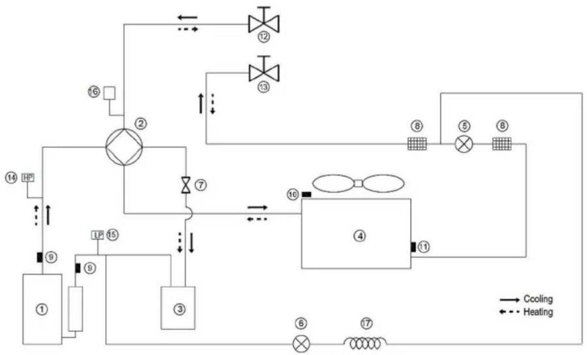
flowchart
graph TD
    A["①"] --> B["②"]
    B --> C["③"]
    C --> D["④"]
    D --> E["⑤"]
    E --> F["⑥"]
    F --> G["⑦"]
    G --> H["⑧"]
    H --> I["⑨"]
    I --> J["⑩"]
    J --> K["⑪"]
    K --> L["⑫"]
    L --> M["⑬"]
    M --> N["⑭"]
    N --> O["⑮"]
    O --> P["⑯"]
    P --> Q["⑰"]
    Q --> R["⑱"]
    R --> S["⑲"]
    S --> T["⑳"]
    T --> U["㉑"]
    U --> V["㉒"]
    V --> W["㉓"]
    W --> X["㉔"]
    X --> Y["㉕"]
    Y --> Z["㉖"]
    Z --> AA["㉗"]
    AA --> AB["㉘"]
    AB --> AC["㉙"]
    AC --> AD["㉚"]
    AD --> AE["㉛"]
    AE --> AF["㉜"]
    AF --> AG["㉝"]
    AG --> AH["㉟"]
    AH --> AI["㉟c"]
    AI --> AJ["㉞"]
    AJ --> AK["㉟d"]
    AK --> AL["㉟e"]
    AL --> AM["㉟f"]
    AM --> AN["㉟g"]
    AN --> AO["㉟h"]
    AO --> AP["㉟i"]
    AP --> AQ["㉟j"]
    AQ --> AR["㉟k"]
    AR --> AS["㉟l"]
    AS --> AT["㉟m"]
    AT --> AU["㉟n"]
    AU --> AV["㉟o"]
    AV --> AW["㉟p"]
    AW --> AX["㉟q"]
    AX --> AY["㉟r"]
    AY --> AZ["㉟t"]
    AZ --> BA["㉟u"]
    BA --> BB["㉟v"]
    BB --> BC["㉟w"]
    BC --> BD["㉟x"]
    BD --> BE["㉟y"]
    BE --> BF["㉟z"]
| Item | Description | Item | Description |
| 1 | Compressor | 10 | Outdoor temperature sensor |
| 2 | 4-Way Valve | 11 | Outdoor exchanger sensor |
| 3 | Gas-liquid separator | 12 | Stop valve (gas) |
| 4 | Air side heat exchanger | 13 | Stop valve (liquid) |
| 5 | Electronic expansion Valve | 14 | High Pressure Switch |
| 6 | Single-way electromagnetic valve | 15 | Low Pressure Switch |
| 7 | Pipe joint | 16 | Pressure valve |
| 8 | Filter | 17 | Capillary |
| 9 | Discharge line sensor |
ANNEX B: Electrically controlled wiring diagram 4\~10kW
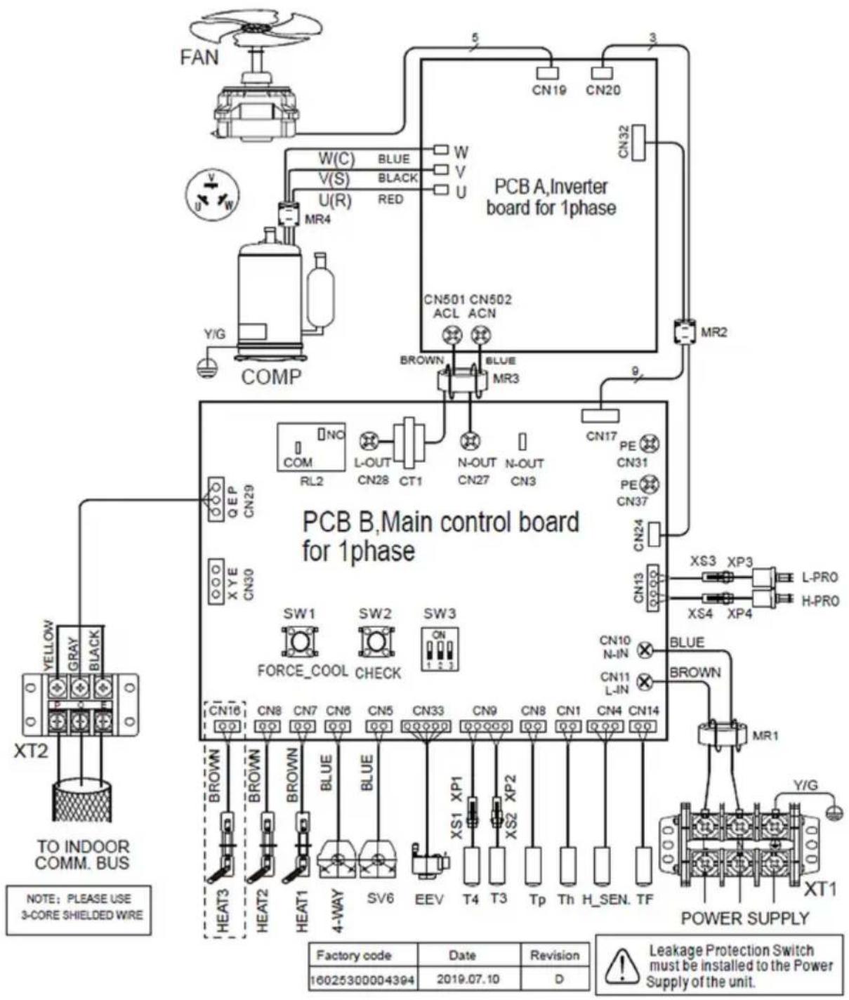
Table1: The environment temperature curve of the low temperature setting for heating
| T4 | ≤ -20 | -19 | -18 | -17 | -16 | -15 | -14 | -13 | -12 | -11 | -10 | -9 | -8 | -7 | -6 | -5 | -4 | -3 | -2 | -1 | 0 | |
| 1-T1S | 38 | 38 | 38 | 38 | 37 | 37 | 37 | 37 | 37 | 37 | 36 | 36 | 36 | 36 | 36 | 36 | 36 | 35 | 35 | 35 | 35 | |
| 2- T1S | 35 | 35 | 35 | 35 | 34 | 34 | 34 | 34 | 34 | 34 | 34 | 34 | 33 | 33 | 33 | 33 | 33 | 33 | 33 | 33 | 32 | |
| 3- T1S | 33 | 33 | 33 | 33 | 33 | 33 | 33 | 32 | 32 | 32 | 32 | 32 | 32 | 32 | 32 | 32 | 32 | 32 | 32 | 32 | 31 | |
| 4- T1S | 35 | 35 | 35 | 34 | 34 | 34 | 34 | 34 | 34 | 33 | 33 | 33 | 33 | 33 | 33 | 32 | 32 | 32 | 32 | 32 | 31 | |
| 5- T1S | 33 | 33 | 33 | 33 | 32 | 32 | 32 | 32 | 32 | 32 | 32 | 32 | 31 | 31 | 31 | 31 | 31 | 31 | 31 | 31 | 30 | |
| 6- T1S | 31 | 31 | 31 | 31 | 30 | 30 | 30 | 30 | 30 | 30 | 30 | 30 | 29 | 29 | 29 | 29 | 29 | 29 | 29 | 29 | 28 | |
| 7 -T1S | 29 | 29 | 29 | 29 | 29 | 29 | 29 | 28 | 28 | 28 | 28 | 28 | 28 | 28 | 28 | 28 | 28 | 28 | 28 | 28 | 27 | |
| 8- T1S | 29 | 29 | 29 | 29 | 28 | 28 | 28 | 28 | 28 | 28 | 28 | 28 | 27 | 27 | 27 | 27 | 27 | 27 | 27 | 27 | 26 | |
| T4 | 1 | 2 | 3 | 4 | 5 | 6 | 7 | 8 | 9 | 10 | 11 | 12 | 13 | 14 | 15 | 16 | 17 | 18 | 19 | ≥ 20 | ||
| 1-T1S | 35 | 35 | 35 | 35 | 34 | 34 | 34 | 34 | 34 | 33 | 33 | 33 | 33 | 33 | 33 | 33 | 32 | 32 | 32 | 32 | 32 | |
| 2- T1S | 32 | 32 | 32 | 32 | 32 | 32 | 32 | 31 | 31 | 31 | 31 | 31 | 31 | 31 | 31 | 30 | 30 | 30 | 30 | 30 | 30 | |
| 3- T1S | 31 | 31 | 31 | 31 | 31 | 31 | 31 | 31 | 31 | 31 | 31 | 31 | 31 | 30 | 30 | 30 | 30 | 30 | 30 | 30 | 30 | |
| 4- T1S | 31 | 31 | 31 | 31 | 31 | 30 | 30 | 30 | 30 | 30 | 30 | 29 | 29 | 29 | 29 | 29 | 29 | 28 | 28 | 28 | 28 | |
| 5- T1S | 30 | 30 | 30 | 30 | 30 | 30 | 30 | 29 | 29 | 29 | 29 | 29 | 29 | 29 | 29 | 28 | 28 | 28 | 28 | 28 | 28 | |
| 6- T1S | 28 | 28 | 28 | 28 | 28 | 28 | 28 | 27 | 27 | 27 | 27 | 27 | 27 | 27 | 27 | 26 | 26 | 26 | 26 | 26 | 26 | |
| 7 -T1S | 27 | 27 | 27 | 27 | 27 | 27 | 27 | 27 | 27 | 27 | 27 | 27 | 27 | 26 | 26 | 26 | 26 | 26 | 26 | 26 | 26 | |
| 8- T1S | 26 | 26 | 26 | 26 | 26 | 26 | 26 | 25 | 25 | 25 | 25 | 25 | 25 | 25 | 25 | 24 | 24 | 24 | 24 | 24 | 24 | |
Table2 The environment temperature curve of the high temperature setting for heating
| T4 | ≤ -20 | -19 | -18 | -17 | -16 | -15 | -14 | -13 | -12 | -11 | -10 | -9 | -8 | -7 | -6 | -5 | -4 | -3 | -2 | -1 | 0 |
| 1-T1S | 55 | 55 | 55 | 55 | 54 | 54 | 54 | 54 | 54 | 54 | 54 | 54 | 53 | 53 | 53 | 53 | 53 | 53 | 53 | 52 | |
| 2-T1S | 55 | 55 | 54 | 54 | 54 | 54 | 53 | 53 | 53 | 53 | 52 | 52 | 52 | 52 | 51 | 51 | 51 | 51 | 50 | 50 | |
| 3-T1S | 55 | 54 | 54 | 53 | 53 | 53 | 52 | 52 | 52 | 51 | 51 | 50 | 50 | 50 | 49 | 49 | 49 | 48 | 48 | 47 | |
| 4-T1S | 50 | 50 | 50 | 50 | 49 | 49 | 49 | 49 | 49 | 49 | 49 | 49 | 48 | 48 | 48 | 48 | 48 | 48 | 48 | 47 | |
| 5-T1S | 50 | 50 | 49 | 49 | 49 | 49 | 48 | 48 | 48 | 48 | 47 | 47 | 47 | 47 | 46 | 46 | 46 | 46 | 45 | 45 | |
| 6-T1S | 45 | 45 | 45 | 45 | 44 | 44 | 44 | 44 | 44 | 44 | 44 | 44 | 43 | 43 | 43 | 43 | 43 | 43 | 43 | 42 | |
| 7-T1S | 45 | 45 | 44 | 44 | 44 | 44 | 43 | 43 | 43 | 43 | 42 | 42 | 42 | 42 | 41 | 41 | 41 | 41 | 40 | 40 | |
| 8-T1S | 40 | 40 | 40 | 40 | 39 | 39 | 39 | 39 | 39 | 39 | 39 | 39 | 38 | 38 | 38 | 38 | 38 | 38 | 38 | 37 | |
| T4 | 1 | 2 | 3 | 4 | 5 | 6 | 7 | 8 | 9 | 10 | 11 | 12 | 13 | 14 | 15 | 16 | 17 | 18 | 19 | ||
| 1-T1S | 52 | 52 | 52 | 52 | 52 | 52 | 52 | 51 | 51 | 51 | 51 | 51 | 51 | 51 | 50 | 50 | 50 | 50 | 50 | 50 | |
| 2-T1S | 50 | 49 | 49 | 49 | 49 | 48 | 48 | 48 | 48 | 47 | 47 | 47 | 47 | 46 | 46 | 46 | 46 | 45 | 45 | 45 | |
| 3-T1S | 47 | 46 | 46 | 46 | 45 | 45 | 45 | 44 | 44 | 44 | 43 | 43 | 43 | 42 | 42 | 41 | 41 | 41 | 40 | 40 | |
| 4-T1S | 47 | 47 | 47 | 47 | 47 | 47 | 47 | 46 | 46 | 46 | 46 | 46 | 46 | 46 | 46 | 45 | 45 | 45 | 45 | 45 | |
| 5-T1S | 45 | 44 | 44 | 44 | 43 | 43 | 43 | 43 | 42 | 42 | 42 | 42 | 41 | 41 | 41 | 41 | 40 | 40 | 40 | ||
| 6-T1S | 42 | 42 | 42 | 42 | 42 | 42 | 42 | 41 | 41 | 41 | 41 | 41 | 41 | 41 | 40 | 40 | 40 | 40 | 40 | 40 | |
| 7-T1S | 40 | 39 | 39 | 39 | 39 | 38 | 38 | 38 | 38 | 37 | 37 | 37 | 37 | 36 | 36 | 36 | 36 | 35 | 35 | 35 | |
| 8-T1S | 37 | 37 | 37 | 37 | 37 | 37 | 37 | 36 | 36 | 36 | 36 | 36 | 36 | 36 | 36 | 35 | 35 | 35 | 35 | 35 |
The automatic setting curve
The automatic setting curve is the ninth curve, this is the calculation:
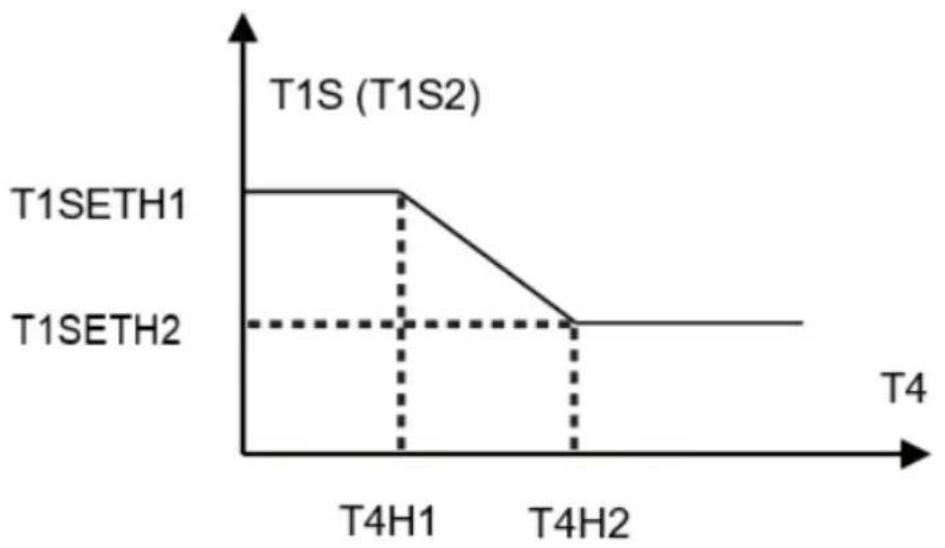
line
| T4 | T1S (T1S2) | | ------ | ---------- | | T4H1 | T1SETH1 | | T4H2 | T1SETH2 |State: In the setting the wired controller, if T4H2<T4H1, then exchange their value; if T1SETH1<T1SETH2, then exchange their value.
Table3 The environment temperature curve of the low temperature setting for cooling
| T4 | -10 ≤ T4 < 15 | 15 ≤ T4 < 22 | 22 ≤ T4 < 30 | 30 ≤ T4 < 46 |
| 1 - T1S | 18 | 11 | 8 | 5 |
| T4 | -10 ≤ T4 < 15 | 15 ≤ T4 < 22 | 22 ≤ T4 < 30 | 30 ≤ T4 < 46 |
| 2 - T1S | 17 | 12 | 9 | 6 |
| T4 | -10 ≤ T4 < 15 | 15 ≤ T4 < 22 | 22 ≤ T4 < 30 | 30 ≤ T4 < 46 |
| 3 - T1S | 18 | 13 | 10 | 7 |
| T4 | -10 ≤ T4 < 15 | 15 ≤ T4 < 22 | 22 ≤ T4 < 30 | 30 ≤ T4 < 46 |
| 4 - T1S | 19 | 14 | 11 | 8 |
| T4 | -10 ≤ T4 < 15 | 15 ≤ T4 < 22 | 22 ≤ T4 < 30 | 30 ≤ T4 < 46 |
| 5 - T1S | 20 | 15 | 12 | 9 |
| T4 | -10 ≤ T4 < 15 | 15 ≤ T4 < 22 | 22 ≤ T4 < 30 | 30 ≤ T4 < 46 |
| 6 - T1S | 21 | 16 | 13 | 10 |
| T4 | -10 ≤ T4 < 15 | 15 ≤ T4 < 22 | 22 ≤ T4 < 30 | 30 ≤ T4 < 46 |
| 7 -T1S | 22 | 17 | 14 | 11 |
| T4 | -10 ≤ T4 < 15 | 15 ≤ T4 < 22 | 22 ≤ T4 < 30 | 30 ≤ T4 < 46 |
| 8 - T1S | 23 | 18 | 15 | 12 |
Table4 The environment temperature curve of the high temperature setting for cooling
| T4 | -10 ≤ T4 < 15 | 15 ≤ T4 < 22 | 22 ≤ T4 < 30 | 30 ≤ T4 < 46 |
| 1 - T1S | 22 | 20 | 18 | 16 |
| T4 | -10 ≤ T4 < 15 | 15 ≤ T4 < 22 | 22 ≤ T4 < 30 | 30 ≤ T4 < 46 |
| 2 - T1S | 20 | 19 | 18 | 17 |
| T4 | -10 ≤ T4 < 15 | 15 ≤ T4 < 22 | 22 ≤ T4 < 30 | 30 ≤ T4 < 46 |
| 3- T1S | 23 | 21 | 19 | 17 |
| T4 | -10 ≤ T4 < 15 | 15 ≤ T4 < 22 | 22 ≤ T4 < 30 | 30 ≤ T4 < 46 |
| 4- T1S | 21 | 20 | 19 | 18 |
| T4 | -10 ≤ T4 < 15 | 15 ≤ T4 < 22 | 22 ≤ T4 < 30 | 30 ≤ T4 < 46 |
| 5 - T1S | 24 | 22 | 20 | 18 |
| T4 | -10 ≤ T4 < 15 | 15 ≤ T4 < 22 | 22 ≤ T4 < 30 | 30 ≤ T4 < 46 |
| 6 - T1S | 22 | 21 | 20 | 19 |
| T4 | -10 ≤ T4 < 15 | 15 ≤ T4 < 22 | 22 ≤ T4 < 30 | 30 ≤ T4 < 46 |
| 7 -T1S | 25 | 23 | 21 | 19 |
| T4 | -10 ≤ T4 < 15 | 15 ≤ T4 < 22 | 22 ≤ T4 < 30 | 30 ≤ T4 < 46 |
| 8 - T1S | 23 | 22 | 21 | 20 |
The automatic setting curve
The automatic setting curve is the ninth curve, this is the calculation
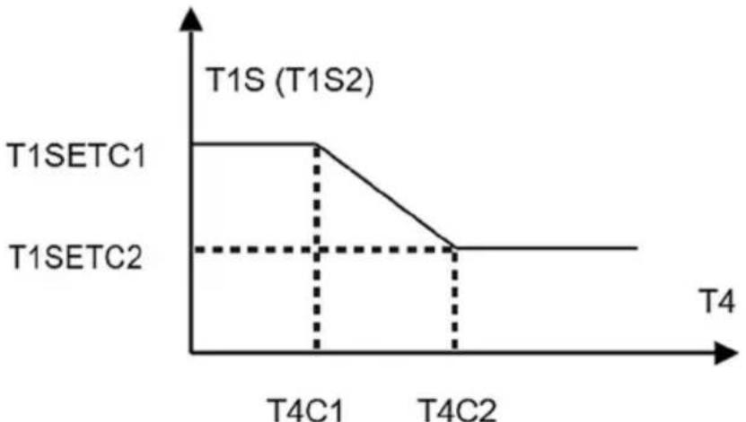
line
| Time Point | T1SETC1 | T1SETC2 | | ---------- | ------- | ------- | | T4C1 | High | Low | | T4C2 | Low | Low |State: In the setting the wired controller, if T4C2<T4C1, then exchange their value; if T1SETC1<T1SETC2, then exchange their value.
CONTENTS
GENERAL SAFETY PRECAUTIONS 3
About the documentation 3
For the user 3
A GLANCE OF THE USER INTERFACE 4
The appearance of the wired controller 4
Status icons 4
USING HOME PAGES 5
MAIN STRUCTURE 8
About the menu structure 8
To go to the menu structure 8
To navigate in the menu structure 8
BASIC USAGE 8
Screen Unlock 9
Turning ON/OFF controls 9
Adjusting the temperature 12
Adjusting space operation mode 12
OPERATION 13
Operation Mode 13
Preset Temperature 14
Domestic Hot Water (DHW) 17
Schedule 19
Options 22
Child Lock 21
Service Information 26
Operation Parameter 27
For Serviceman 28
Network Configuration Guidelines 29
MENU STRUCTURE: OVERVIEW 32
DISPOSAL GUIDELINES 37
EU DECLARATION OF CONFORMITY 37
Note: All the pictures in this manual are just schematic diagrams, the actual is the standard
GENERAL SAFETY PRECAUTIONS
About the documentation.

DANGER
Indicates a situation that results in death or serious injury.

WARNING
Indicates a situation that could result in death or serious injury.
DANGER RISK OF ELECTROCUTION
Indicates a situation that results in death or serious injury.
DANGER: RISK OF BURNING
Indicates a situation that could result in burning because of extreme hot or cold temperatures.

CAUTION
Indicates a situation that could result in minor or moderate injury.

NOTE
Indicates a situation that could result in death or serious injury.

CAUTION
Indicates a situation that could result in minor or moderate injury.

NOTE
Indicates a situation that could result in equipment or property damage.

CAUTION
DO NOT rinse the unit. This may cause electric shocks or fire.

INFORMATION
Indicates useful tips or additional information.
For the user
If you are not sure how to operate the unit, contact your installer.
The appliance is not intended for use by persons, including children, with reduced physical, sensory or mental capabilities, or lack of experience and knowledge, unless they have been given supervision or instruction concerning use of the appliance by a person responsible for their safety.
Children must be supervised to ensure that they do not play with the product.
A GLANCE OF THE USER INTERFACE
The appearance of the wired controller
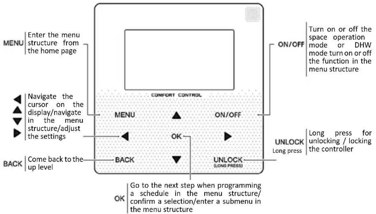
flowchart
graph TD
    A["MENU"] --> B["Enter the menu structure from the home page"]
    B --> C["ON/OFF"]
    C --> D["Turn on or off the space operation mode or DHW mode turn on or off the function in the menu structure"]
    A --> E["Navigate the cursor on the display/navigate in the menu structure/adjust the settings"]
    E --> F["ON/OFF"]
    F --> G["ON/OFF CONTROL"]
    G --> H["ON/OFF"]
    H --> I["ON/OFF"]
    I --> J["ON/OFF"]
    J --> K["ON/OFF"]
    K --> L["ON/OFF"]
    L --> M["ON/OFF"]
    M --> N["ON/OFF"]
    N --> O["ON/OFF"]
    O --> P["ON/OFF"]
    P --> Q["ON/OFF"]
    Q --> R["ON/OFF"]
    R --> S["ON/OFF"]
    S --> T["ON/OFF"]
    T --> U["ON/OFF"]
    U --> V["ON/OFF"]
    V --> W["ON/OFF"]
    W --> X["ON/OFF"]
    X --> Y["ON/OFF"]
    Y --> Z["ON/OFF"]
    Z --> AA["ON/OFF"]
    AA --> AB["ON/OFF"]
    AB --> AC["ON/OFF"]
    AC --> AD["ON/OFF"]
    AD --> AE["ON/OFF"]
    AE --> AF["ON/OFF"]
    AF --> AG["ON/OFF"]
    AG --> AH["ON/OFF"]
    AH --> AI["ON/OFF"]
    AI --> AJ["ON/OFF"]
    AJ --> AK["ON/OFF"]
    AK --> AL["ON/OFF"]
    AL --> AM["ON/OFF"]
    AM --> AN["ON/OFF"]
    AN --> AO["ON/OFF"]
    AO --> AP["ON/OFF"]
    AP --> AQ["ON/OFF"]
    AQ --> AR["ON/OFF"]
    AR --> AS["ON/OFF"]
    AS --> AT["ON/OFF"]
    AT --> AU["ON/OFF"]
    AU --> AV["ON/OFF"]
    AV --> AW["ON/OFF"]
    AW --> AX["ON/OFF"]
    AX --> AY["ON/OFF"]
    AY --> AZ["ON/OFF"]
    AZ --> BA["ON/OFF"]
    BA --> BB["ON/OFF"]
    BB --> BC["ON/OFF"]
    BC --> BD["ON/OFF"]
    BD --> BE["ON/OFF"]
    BE --> BF["ON/OFF"]
    BF --> BG["ON/OFF"]
    BG --> BH["ON/OFF"]
    BH --> BI["ON/OFF"]
    BI --> BJ["ON/OFF"]
    BJ --> BK["ON/OFF"]
    BK --> BL["ON/OFF"]
    BL --> BM["ON/OFF"]
    BM --> BN["ON/OFF"]
    BN --> BO["ON/OFF"]
    BO --> BP["ON/OFF"]
    BP --> BQ["ON/OFF"]
    BQ --> BR["ON/OFF"]
    BR --> BS["ON/OFF"]
    BS --> BT["ON/OFF"]
    BT --> BU["ON/OFF"]
    BU --> BV["ON/OFF"]
    BV --> BW["ON/OFF"]
    BW --> BX["ON/OFF"]
    BX --> BY["ON/OFF"]
    BY --> BZ["ON/OFF"]
    BZ --> CA["ON/OFF"]
    CA --> CB["ON/OFF"]
    CB --> CC["ON/OFF"]
    CC --> CD["ON/OFF"]
    CD --> CE["ON/OFF"]
    CE --> CF["ON/OFF"]
    CF --> CG["ON/OFF"]
    CG --> CH["ON/OFF"]
    CH --> CI["ON/OFF"]
    CI --> CJ["ON/OFF"]
    CJ --> CK["ON/OFF"]
    CK --> CR["ON/OFF"]
    CR --> CS["ON/OFF"]
    CS --> CT["ON/OFF"]
    CT --> CU["ON/OFF"]
    CU --> CV["ON/OFF"]
    CV --> CW["ON/OFF"]
    CW --> CX["ON/OFF"]
    CX --> CY["ON/OFF"]
    CY --> CZ["ON/OFF"]
Status icons
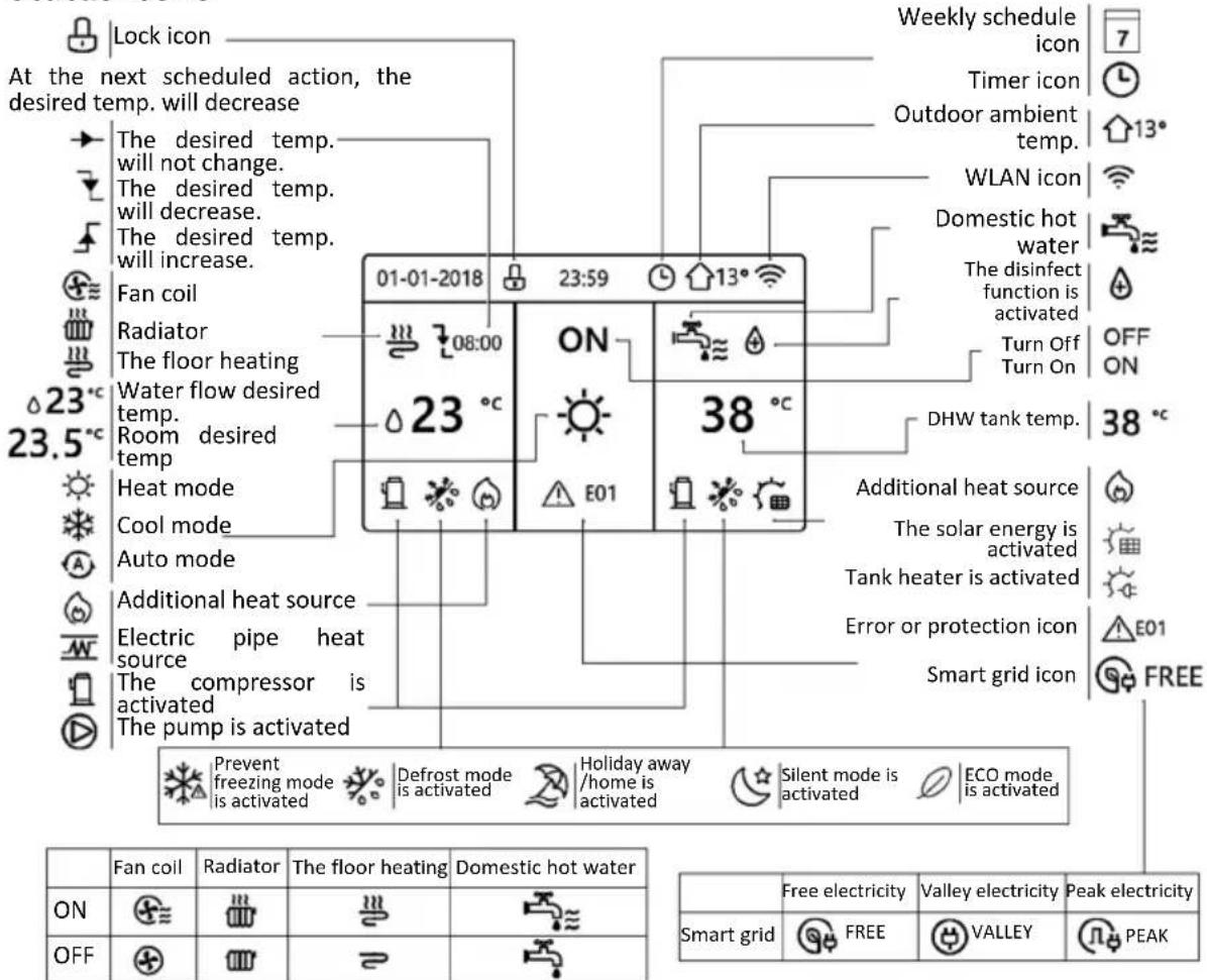
USING HOME PAGES
When you turn on the wired controller, the system will enter the language selection page, You can choose your preferred language, then press OK to enter the home pages. If you don't press OK in 60 seconds, the system will enter in the currently selected language.
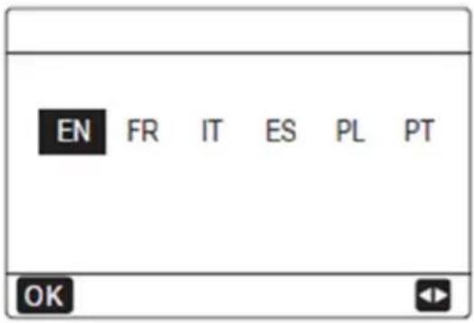
You can use the home pages to read out and change settings that are meant for daily usage. What you can see and do on the home pages is described where applicable. Depending on the system layout, the following home pages may be possible:
• Room desired temperature (ROOM)
• Water flow desired temperature (MAIN)
- DHW tank actual temperature (TANK) DHW=domestic hot water.
Home Page 1
If the WATER FLOW TEMP. is set YES and ROOM TEMP. is set NON. (See "FOR SERVICEMAN" > "TEMP. TYPE SETTING" in "Installation and owner's manual (M-thermal split indoor unit)").
The system has the function including floor heating and domestic water, home page 1 will appear.
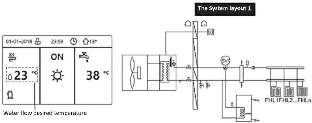
NOTE
All the pictures in the manual are used to explain, the actual pages in the screen may have some difference.
Home Page 2
If the WATER FLOW TEMP. is set NON and ROOM TEMP. is set YES (See "FOR SERVICEMAN" > "TEMP. TYPE SETTING" on "Installation and owner's manual (M-thermal split indoor unit)").
The system has the function including floor heating and domestic hot water, home page 2 will appear:
The System layout 2
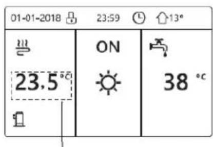
Room desired temperature
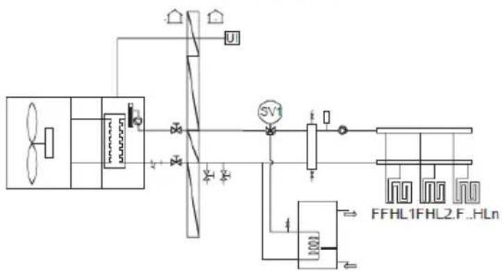
flowchart
graph TD
    A["AC Unit"] --> B["Transformer"]
    B --> C["Pump"]
    C --> D["Control Unit"]
    D --> E["FFHL1FHL2.F..HLn"]
    B --> F["Sensor"]
    B --> G["Ground"]
    C --> H["Switch SV1"]
    H --> I["Control Unit"]
    I --> J["FFHL1FHL2.F..HLn"]
NOTE
The wired controller should be installed in the floor heating room to check the room temperature.
Home Page 3
If the DHW MODE is set NON (See "FOR SERVICEMAN" > "DHW MODE SETTING " in "Installation and owner's manual (M-thermal split indoor unit) ", and if "WATER FLOW TEMP." is set YES, "ROOM TEMP." is set YES, (See "FOR SERVICEMAN" > "TEMP. TYPE SETTING " in "Installation and owner's manual (M-thermal split indoor unit)").
There will be main page and additional page. The system has the function including floor heating and space heating for fan coil, home page 3 will appear:
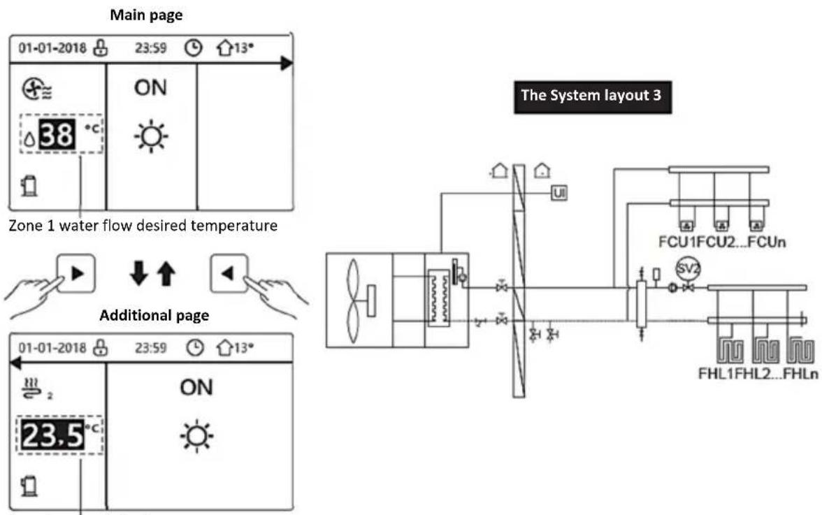
Zone 2 room desired temperature
Home Page 4
If the ROOM THERMOSTAT is set DOUBLE ZONE or DOUBLE ZONE is set YES. There will be main page and addition page. The system has the function including floor cooling, space cooling for fan coil and domestic hot water, home page 4 will appear:
Main page
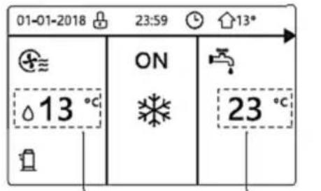
Zone 1 water flow desired temperature
DHW tank real temp.
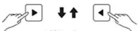
Additional page
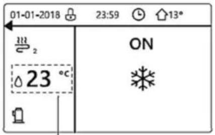
Zone 2 water flow desired temperature
The System layout 4
RT= Room thermostat
flowchart
graph TD
    A["Fan"] --> B["Turbo"]
    B --> C["Control Unit"]
    C --> D["FCU1FCU2...FCUn"]
    C --> E["SV1"]
    C --> F["SV2"]
    C --> G["FHL1FHL2...FHLn"]
    B --> H["Ground"]
    B --> I["Ground"]
    B --> J["Ground"]
    B --> K["Ground"]
    B --> L["Ground"]
    B --> M["Ground"]
    B --> N["Ground"]
    B --> O["Ground"]
    B --> P["Ground"]
    B --> Q["Ground"]
    B --> R["Ground"]
MENU STRUCTURE
About the menu structure
You can use the menu structure to read out and configure settings that are NOT meant for daily usage. What you can see and do in the menu structure is described where applicable. For an overview of the menu structure, see "7 Menu structure: Overview"
To go to the menu structure
From a home page, press "MENU".
Result: The menu structure appear
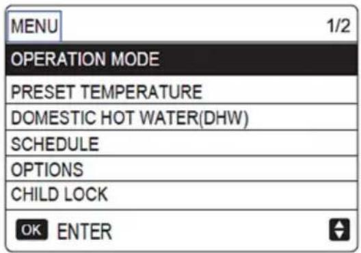
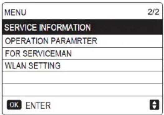
To go to the menu structure
Use"▼"、"▲" to scroll.
BASIC USAGE
Screen Unlock
If the icon 🔒 is on the screen, the controller is locked.
The following page is displayed:
Press any key, the icon 📋 will flash. Long press the "UNLOCK" key. The icon 📋 will disappear, the interface can be controlled.
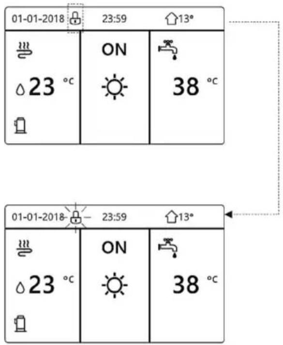
The interface will be locked if there is no handing for a long time(about 120 seconds: it can be set by the interface, see "SERVICE INFORMATION".)
If the interface is unlocked, long press "unlock", the interface will be locked.
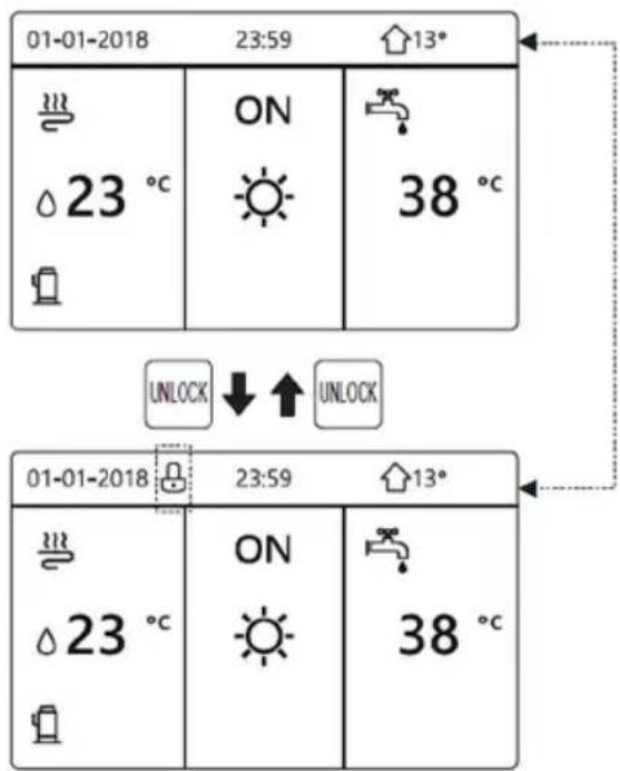
Turning ON/OFF controls
Use the interface to turn on or off the unit for space heating or cooling.
The ON/OFF of the unit can be controlled by the interface if the ROOM THERMOSTAT is NON. (see "ROOM THERMOSTAT SETTING" in "Installation and owner's manual (M-thermal split indoor unit)")
Press "◀"、"▲" on home page, the black cursor will appear:
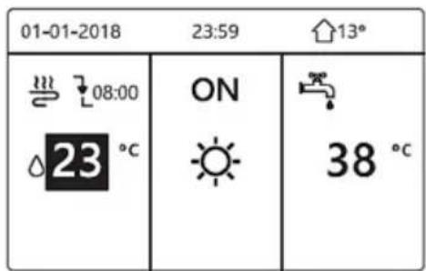
1) When the cursor is on the temperature of space operation mode side (Including heat mode ⚙, cool mode ⚙ and auto mode Ⓐ A ), press "ON/OFF" key to Turn On/Off space heating or cooling.
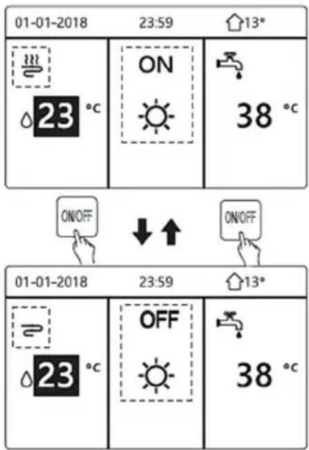
If the DHW TYPE is set NON, then following pages will display:
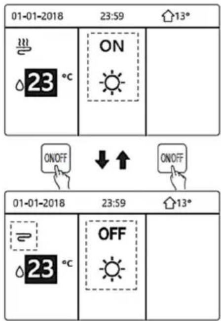
If the TEMP. TYPE is set ROOM TEMP., then following pages will display:
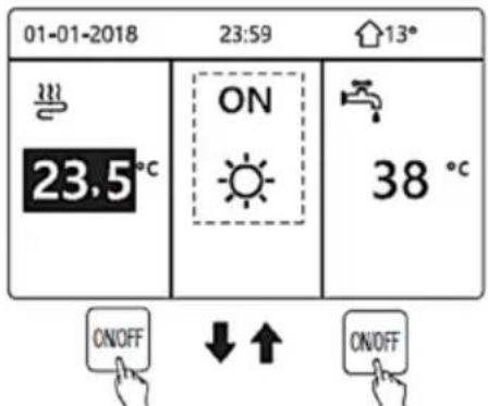
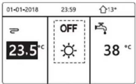
Use the room thermostat to turn on or off the unit for space heating or cooling.
① The room thermostat is not SET NON (see "ROOM THERMOSTAT SETTING" in "Installation and owner's manual (M-thermal split indoor unit)").
The unit for space heating or cooling is turned on or off by the room thermostat, press ON/OFF on the interface, the following page will display:
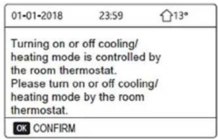
② The room thermostat is SET DOUBLE ZONE (see "ROOM THERMOSTAT SETTING" in "Installation and owner's manual (M-thermal split indoor unit)"). The room thermostat for fan coil is turned off, the room thermostat for the floor heating is turned on, and the unit is running, but the display is OFF. The following page is displayed:
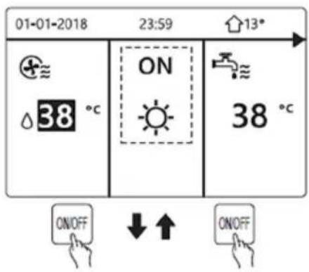
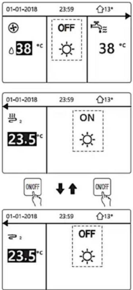
Use the interface to turn on or off the unit for DHW.
Press "▶"、"▼" on home page, the black cursor will appear:
| 01-01-2018 | 23:59 | 13° |
| ON | ||
| △23°C | 38°C |
2) When the cursor is on the temperature of DHW mode. Press "ON/OFF" key to turn on/off the DHW mode.
If the space operation mode is ON, then following pages will display:
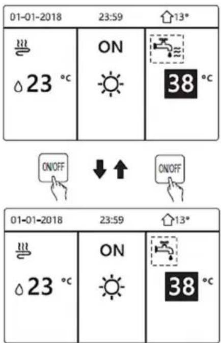
If the space operation mode is OFF, then following pages will display:
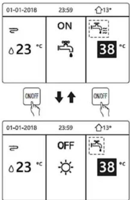
Adjusting the temperature
Press "◀"、"▲" on home page, the black cursor will appear:
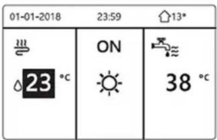
If the cursor is on the temperature, use the "◀"、"▶" to select and use "▼"、"▲" to adjust the temperature.:
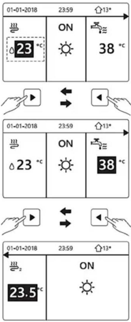
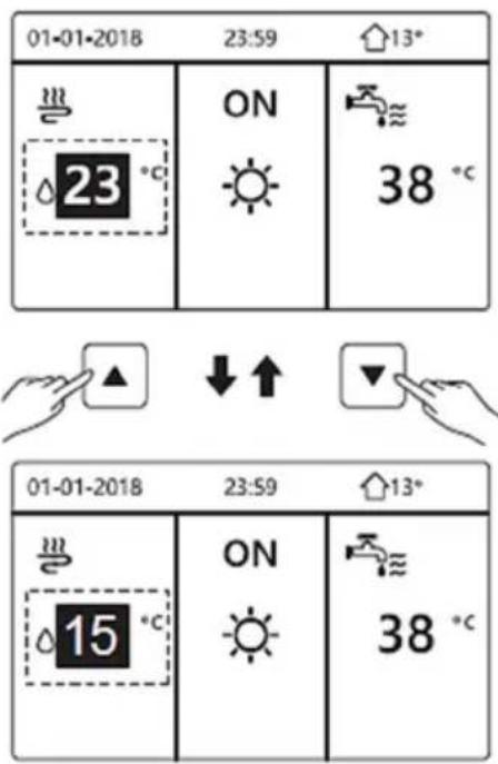
Adjusting space operation mode
Adjusting space operation mode by interface Go to "MENU" > "OPERATION MODE". Press"OK", the following page will appear:
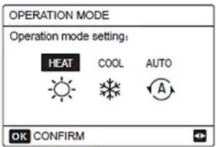
There are three modes to be selected including HEAT, COOL and AUTO mode. Use the "◀", "▶" to scroll, press "OK" to select.
Even you don't press OK button and exit the page by pressing BACK button, the mode would still be effective if the cursor had been moved to the operation mode.
If there is only HEAT (COOL) mode, the following page will appear:
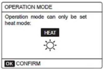
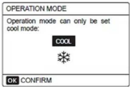
The operation mode can not be changed
| Select | Then the space operation mode is... |
 HEAT HEAT | Always heating mode |
 COOL COOL | Always cooling mode |
 AUTO AUTO | Automatically changed by the software based on the outdoor temperature (and depending on installer settings of the indoor temperature), and takes monthly restrictions into account.Note: Automatic changeover is only possible under certain conditions.See the "FOR SERVICEMAN"> "AUTO MODE SETTING" in "Installation and owner's manual (M-thermal split indoor unit)". |
Adjust space operation mode by the room thermostat, see "ROOM THERMOSTAT" on "Installation and owner's manual (M-thermal split indoor unit)".
Go to "MENU">"OPERATION MODE", if you press any key to select or adjust, the page will appear:
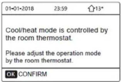
OPERATION
Operation Mode
See "Adjusting space operation mode":
Preset Temperature
PRESET TEMPERATUER has PRESET TEMP.\ WEATHER TEMP. SET\ECO MODE 3 items.
PRESET TEMP.
PRESET TEMP. function is used to set different temperature on different time when the heat mode or cool mode is on.
- PRESET TEMP. = PRESET TEMPERATRE - The PRESET TEMP. function will be off in these conditions.
1) AUTO mode is running.
2) TIMER or WEEKLY SCHEDULE is running.
- Go to "MENU" > "PRESET TEMPERATURE" > "PRESET TEMP". Press "OK".
The following page will appear:
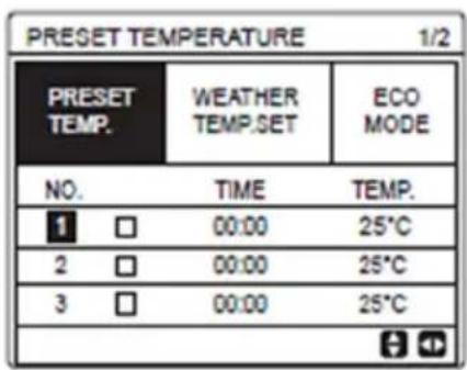
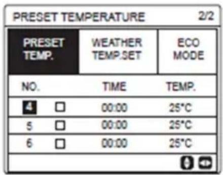
When double zone is activated, The PRESET TEMP. function only works for zone 1.
use "◀"、"▶"、"▼"、"▲" to scroll and use "▼"、"▲" to adjust the time and the temperature.
When the cursor is on "■", as the following page:
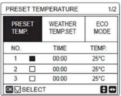
You press "OK", and the "■" becomes "▼". The timer 1 is selected.
You press "OK" again, and the "☑" becomes "■". The timer 1 is unselected.
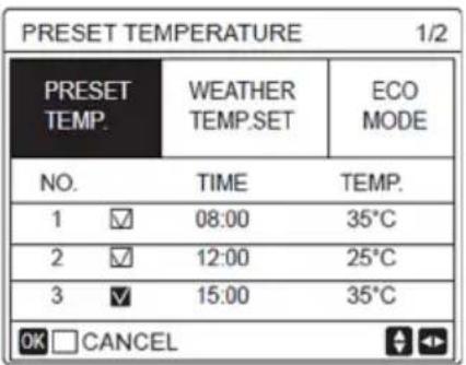
Use "◀", "▶", "▼", "▲" to scroll and use "▼", "▲" to adjust the time and the temperature.
Six periods and six temperatures can be set.
For example:
Now time is 8:00 and temperature is 30°C. We set the PRESET TEMP as following table. The following page will appear:
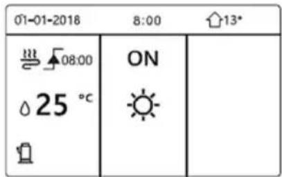
| NO. | TIME | TEMPER |
| 1 | 8:00 | 35°C |
| 2 | 12:00 | 25°C |
| 3 | 15:00 | 35°C |
| 4 | 18:00 | 25°C |
| 5 | 20:00 | 35°C |
| 6 | 23:00 | 25°C |
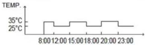
line
| Time | Temperature | | ------ | ----------- | | 8:00 | 35°C | | 12:00 | 25°C | | 15:00 | 35°C | | 18:00 | 25°C | | 20:00 | 35°C | | 23:00 | 25°C |i INFORMATION
When the space operation mode is changed, the PRESET TEMP. is off automatically.
The PRESET TEMP. function can be used in the heat mode or cool mode. But if the operation mode is changed, the PRESET TEMP. function needs to be reset again.
The running preset temperature is invalid when the unit is OFF. It will run according to the next preset temperature when the unit turn on again.
Water Temperature Set
WEATHER TEMP. SET = WEATHER TEMPERATURE SET
WEATHER TEMP.SET function is used to preset the desired water flow temperature depending on the outside air temperature. During the warmer weather the heating is reduced. To save energy, the weather temp.set can decrease the desired water flow temperature when the outdoor air temperature increased in heating mode.
Go to "MENU" > "PRESET TEMPERATURE" > "WEATHER TEMP. SET". Press"OK".
The following page will appear:
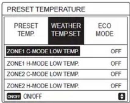
i INFORMATION
WEATHER TEMP. SET have four kinds of curves:
- the curve of the high temperature setting for heating,
- the curve of the low temperature setting for heating,
- the curve of the high temperature setting for cooling.
- the curve of the low temperature setting for cooling. It only have the curve of the high temperature setting for heating, if the high temperature is set for heating.
It only have the curve of the low temperature setting for heating, if the low temperature is set for heating.
It only have the curve of the high temperature setting for cooling, if the high temperature is set for cooling
It only have the curve of the low temperature setting for cooling, if the low temperature is set for cooling.
See "FOR SERVICEMAN"> "COOL MODE SETTING" and > "HEAT MODE SETTING" in "Installation and owner's manual (M-thermal split indoor unit)".
The desired temperature (T1S) can't be adjusted, when the temperature curve is set ON.
If you want to use heat mode in zone 1, you select "ZONE1 H-MODE LOW TEMP". If you want to use cool mode in zone 1, you select "ZONE1 C-MODE LOW TEMP". If you select "ON", the following page will appear:
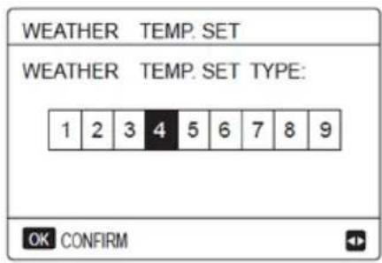
Use '◀", "▶" to scroll.
Press "OK" to select.
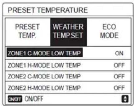
If the weather TEMP.SET is activated, the desired temperature can not be adjusted on the interface. Press the "▼", "▲" to adjust the temperature on home page.
The following page will appear:
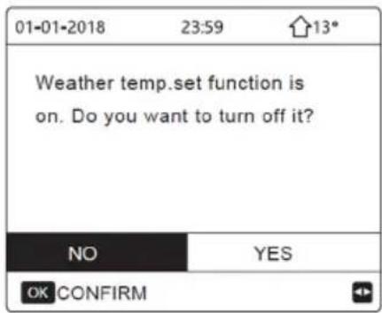
Move to "NO", press "OK" to come back to home page, move to "YES", press "OK" to reset the WEATHER TEMP. SET.
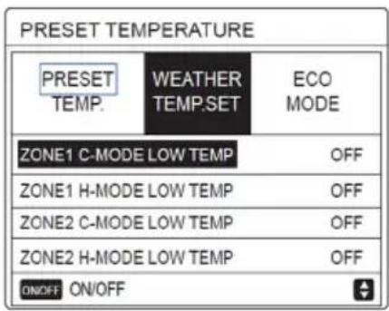
ECO Mode
ECO MODE is used to save energy. Go to "MENU" > "PRESET TEMPERATURE" > "ECO MODE".
Press "OK". The following page will appear:
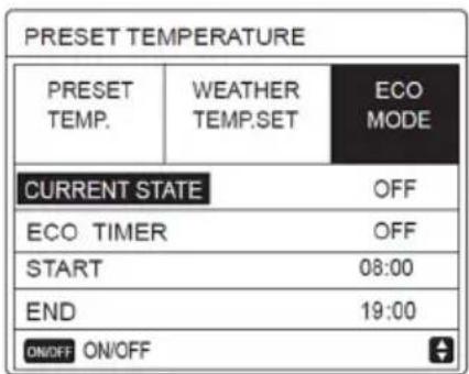
Press "ON/OFF". The following page will appear:
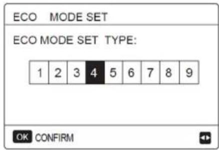
Use '◀", "▶" to scroll.
Press "OK" to select. The following page will appear:
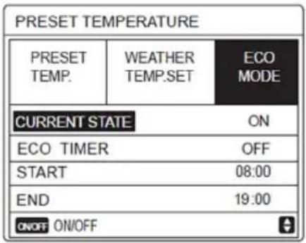
Use "ON/OFF" to turn ON or OFF, and use "▼", "▲" to scroll.
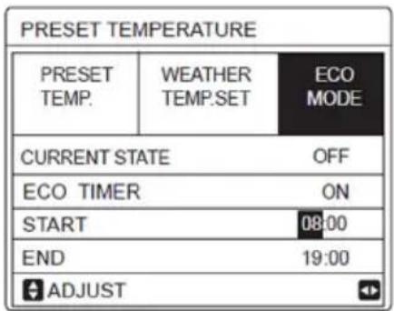
When the cursor is on the "START" or on the "END", you can use "◀", "▶", "▼", "▲" to scroll and use "▼", "▲" to adjust the time.
i INFORMATION
ECO MODE SET have two kinds of curves:
- the curve of the high temperature setting for heating,
- the curve of the low temperature setting for heating,
It only have the curve of the high temperature setting for heating, if the high temperature is set for heating.
- See "FOR SERVICEMAN">"HEAT MODE SETTING" in "Installation and owner's manual (M-thermal split indoor unit)".
- The desired temperature (T1S) can't be adjusted, when the ECO mode is ON.
- You can select the low or hige temperature setting for heating to see the "Table 1\~2".
- If ECOMODE is ON and ECO TIMER is OFF, the unit run ECO mode all the time.
- If ECO MODE is ON and ECO TIMER is ON, the unit run ECO mode according to the start time and end time.
DOMESTIC HOT WATER (DHW)
DHW mode typically consists of the following :
The DISINFECT function is used to kill the legionella. In disinfect function the tank temperature will be reached 65\~70°C forcibly.
The disinfect temperature is set in FOR SERCICEMAN.
See "FOR SERCICEMAN" > "DHW MODE" > "DISINFECT" in "Installation and owner's manual (M-thermal split indoor unit)".
Go to "MENU" > "DOMESTIC HOT WATER" > "DISINFECT".
Press "OK". The following page will appear
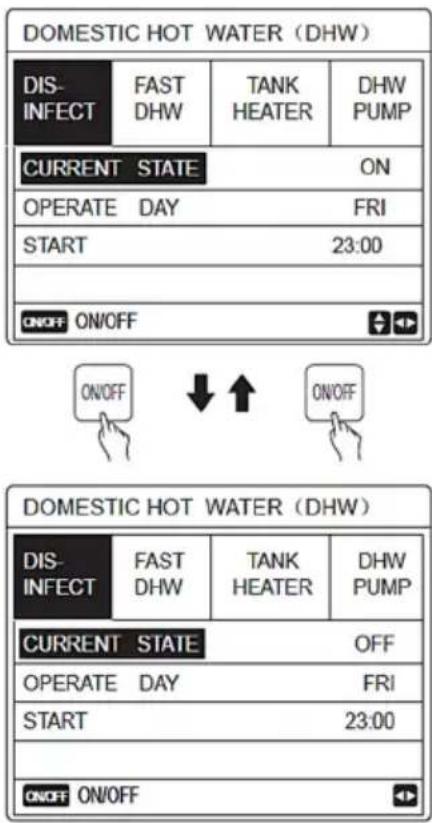
Use "◀", "▶", "▼", "▲" to scroll and use "▼", "▲" to adjust the parameters when setting "OPERATE DAY" and "START".
If the OPERATE DAY is set FRIDAY and the START is set 23:00, the disinfect function will active on 23:00 Friday.
If the disinfect function is running, the following page will appear:
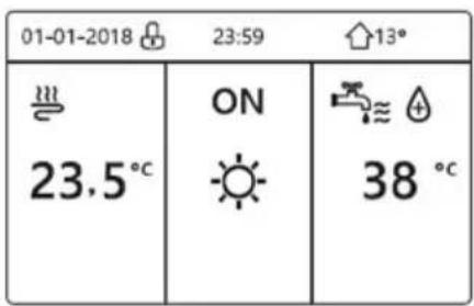
Fast DHW
The FAST DHW function is used to force the system to operate in DHW mode.
The heat pump and the booster heater or addition heater will operate for DHW mode together, and the DHW desired temperature will be changed to 60°C.
Go to MENU> DOMESTIC HOT WATER >FAST DHW.
Press "OK"
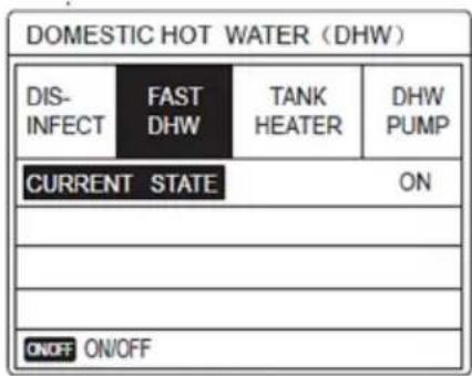

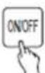
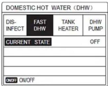
Use "ON/OFF" key to select ON or "OFF".

INFORMATION
- invalid, and if CURRENT STATE is ON, the
- FAST DHW function is effective.
- The FAST DHW function is once effective.
TANK Heater
The tank heater function is used to force the tank heater to heat the water in tank. In the same situation, the cooling or heating is required and the heat pump system is operating for cooling or heating, however there still is a demand for the hot water.
Also, even if the heat pump system fails, TANK HEATER can be used to heat water in tank.
Go to "MENU" > "DOMESTIC HOT WATER" > "TANK".
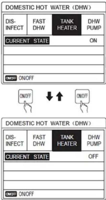
Use "ON/OFF" to select ON or OFF.
Use "BACK" to exit.
If TANK HEATER is effect, the following page will appear.
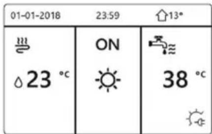

INFORMATION
If CURRENT STATE is OFF, TANK HEATER is invalid.
If the T5 (sensor of tank) is fault, tank heater can't work.
DHW Pump
The DHW PUMP function is used to return water of the water net. Go to "MENU" > "DOMESTIC HOT WATER" > "DHW PUMP".
Press "OK".
The following page will appear:
| DOMESTIC HOT WATER (DHW) 1/2 | |||
| DIS-INFECT | FAST DHW | TANK HEATER | DHW PUMP |
| NO. | START | NO. | START |
| T1 □ | 00:00 | T4 □ | 00:00 |
| T2 □ | 00:00 | T5 □ | 00:00 |
| T3 □ | 00:00 | T6 □ | 00:00 |
| DOMESTIC HOT WATER (DHW) 2/2 | |||
| DIS-INFECT | FAST DHW | TANK HEATER | DHW PUMP |
| NO. | START | NO. | START |
| T7 □ | 00:00 | T10 □ | 00:00 |
| T8 □ | 00:00 | T11 □ | 00:00 |
| T9 □ | 00:00 | T12 □ | 00:00 |
| + < | |||
Move to "■", press "OK" to select or unselect. (☑ the timer is selected, □ the timer is unselected.)
| DOMESTIC HOT WATER (DHW) 1/2 | |||
| DIS-INFECT | FAST DHW | TANK HEATER | DHW PUMP |
| NO. | START | NO. | START |
| T1 ☑ | 00:00 | T4 □ | 00:00 |
| T2 □ | 00:00 | T5 □ | 00:00 |
| T3 □ | 00:00 | T6 □ | 00:00 |
Use "◀", "▶", "▼", "▲" to scroll and use "▼", "▲" to adjust the parameters.
For example: you have set the parameter about the DHW PUMP (See "FOR SERVICEMAN">"DHW MODE SETTING" on "Installation and owner's manual (M-thermal split indoor unit)".
PUMP RUNNING TIME is 30 minutes.
Set as follows:
| NO. | START |
| 1 | 6:00 |
| 2 | 7:00 |
| 3 | 8:00 |
| 4 | 9:00 |
The PUMP will run as follows:
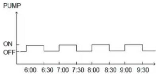
line
| Time | PUMP | |-------|------| | 6:00 | ON | | 6:30 | ON | | 7:00 | ON | | 7:30 | ON | | 8:00 | ON | | 8:30 | ON | | 9:00 | ON | | 9:30 | ON |SCHEDULE
SCHEDULE menu contents as follows:
The following page will appear:
1) TIMER
2) WEEKLY SCHEDULE
3) SCHEDULE CHECK
4) CANCEL TIMER
Timer
If the weekly schedule function is on, the timer is off, the later setting is effective. If the Timer is activated, ⏻ is displayed on home page.
| SCHEDULE 1/2 | ||||
| TIMER | WEEKLY SCHEDULE | SCHEDULE CHECK | CANCEL TIMER | |
| NO. | START | END | MODE | TEMP |
| 1 □ | 00:00 | 00:00 | HEAT | 0°C |
| 2 □ | 00:00 | 00:00 | HEAT | 0°C |
| 3 □ | 00:00 | 00:00 | HEAT | 0°C |
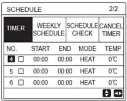
Use "◀", "▶", "▼", "▲" to scroll and use "▼", "▲" to adjust the temperature.
Move to "■", press "OK" to select or unselect. ((☑ the timer is selected, □ the timer is unselected.). six timers can be set.
If you want to cancel the TIMER, you move the cursor to "☑", press "OK", the ☑ become □, the timer is invalid.
If you set the start time later than the end time or the temperature out of range of the mode.
The following page will appear:
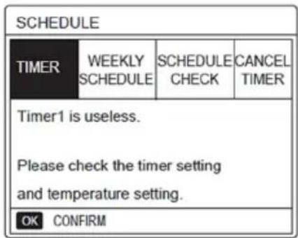
Example:
Six timer is set as following:
| NO. | START | END | MODE | TEMP |
| T1 | 1: 00 | 3: 00 | DHW | 50℃ |
| T2 | 7: 00 | 9: 00 | HEAT | 28℃ |
| T3 | 11: 30 | 13: 00 | COOL | 20℃ |
| T4 | 14: 00 | 16: 00 | HEAT | 28℃ |
| T5 | 15: 00 | 19: 00 | COOL | 20℃ |
| T6 | 18: 00 | 23: 30 | DHW | 50℃ |
The unit will run as following:
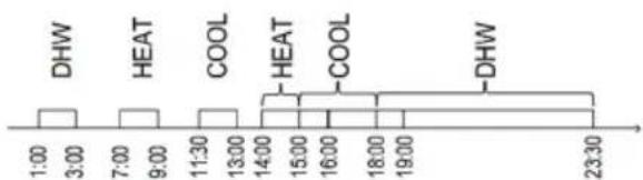
The operation of the controller at the following time:
| TIME | The operatin of the controller |
| 1:00 | DHW mode is turned ON |
| 3:00 | DHW mode is turned OFF |
| 7:00 | HEAT MODE is turned ON |
| 9:00 | HEAT MODE is turned OFF |
| 11:30 | COOL MODE is turned ON |
| 13:00 | COOL MODE is turned OFF |
| 14:00 | HEAT MODE is turned ON |
| 15:00 | COOL MODE is turned ON and HEAT MODE is turned OFF |
| 18:00 | DHW MODE is turned ON and COOL MODE is turned OFF |
| 23:30 | DHW mode is turned OFF |
i INFORMATION
If the start time is same to the end time in one timer, the timer is invalid.
Weekly Schedule
If the timer function is on and the weekly schedule is off, the later setting is effective. If WEEKLY SCHEDULE is activated, icon 7 is displayed on the home page.
Go to "MENU" > "SCHEDULE" > "WEEKLY SCHEDULE".
Press "OK". The following page will appear:
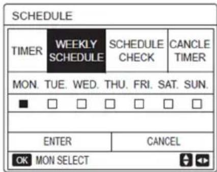
First select the days of the week you wish to schedule.
Use "◀", "▶" to scroll, press "OK" to select on unselect the day.
"MON" means that the day is selected, "MON" means that the day is unselected:
i INFORMATION
We must set two days at least when we want to enable WEEKLY SCHEDULE function.
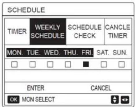
Use "◀" or "▶" to SET, press "ENTER".
The Monday to Friday are selected to be scheduled and they have the same schedule.
The following pages will appear:
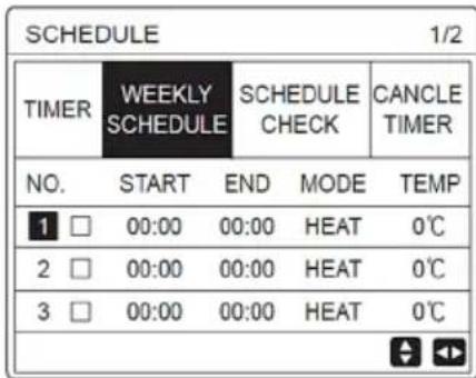
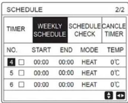
Use "◀", "▶", "▼", "▲" to scroll and adjust the time, the mode and the temperature. Timers can be set, including start time and end time, mode and temperature.
The mode includes heat mode, cool mode and DHW mode.
The setting method refer to timer setting. The end time must be later than the start time. Otherwise this will show that Timer is useless.
Schedule check
Schedule check can only check the weekly schedule.
Go to "MENU" > "SCHEDULE" > "SCHEDULE" CHECK".
Press "OK". The following page will appear
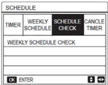
| WEEKLY SCHEDULE CHECK | |||||
| DAY | NO | MODE | SET | START | END |
| MON □ | T1 □ | HEAT | 0℃ | 00:00 | 00:00 |
| T2 □ | HEAT | 0℃ | 00:00 | 00:00 | |
| T3 □ | HEAT | 0℃ | 00:00 | 00:00 | |
| T4 □ | HEAT | 0℃ | 00:00 | 00:00 | |
| T5 □ | HEAT | 0℃ | 00:00 | 00:00 | |
| T6 □ | HEAT | 0℃ | 00:00 | 00:00 | |
Press "▼"、"▲",the timer from Monday to Sunday will appear
Cancel Timer
Go to "MENU" > "SCHEDULE" > "CANCEL TIMER".
Press "OK".
The following page will appear:
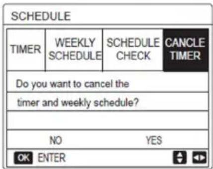
Use "◀", "▶", "▼", "▲" to move to "YES", press "OK" to cancel timer. If you want to exit CANCEL TIMER, press "BACK".
If TIMER or WEEKLY SCHEDULE is activated, timer icon " ℙ" or weekly schedule icon " 7" will display on the home page.
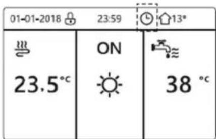
If TIMER or WEEKLY SCHEDULE is canceled, timer icon " 🔊" or weekly schedule icon " ☐" will disappear on the home page.
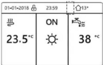
i INFORMATION
You have to reset TIMER/WEEKLY SCHEDULE, if you change the WATER FLOW TEMP. to the ROOM TEMP. or you change the ROOM TEMP. to the WATER FLOW TEMP.
The TIMER or WEEKLY SCHEDULE is invalid, if ROOM THERMOSTAT is effect.
i INFORMATION
- The ECO or COMFORT MODE has the highest priority, the TIMER or WEEKLY SCHEDULE has the second priority and the PRESET TEMP. Or WEATHER TEMP. SET has the lowest priority.
- The PRESET TEMP. or WEATHER TEMP. SET becomes invalid, when we set the ECO or COMFORT valid. We must reset the PRESET TEMP. or WEATHER TEMP. SET when we set the ECO or COMFORT invalid.
- TIMER or WEEKLY SCHEDULE is invalid when ECO or COMFORT is valid. TIMER or WEEKLY SCHEDULE is activated when the ECO or COMFORT is not running.
i INFORMATION
- TIMER and WEEKLY SCHEDULE are on the same priority. The later setting function is valid. The PRESET TEMP. becomes invalid when TIMER or WEEKLY SCHEDULE is valid. The WEATHER TEMP. SET is not affected by the setting of TIMER or WEEKLY SCHEDULE.
- PRSET TEMP. and WATHER TEMP.SET are on the same priority. The later setting function is valid.
i INFORMATION
All about the time set items (PRESET TEMP., ECO/COMFORT, DISINFECT, DHW PUMP, TIMER, WEEKLY SCHEDULE, SILENCE MODE, HOLIDAY HOME), the ON/OFF of the corresponding function can be activated from the start time to the end time.
OPTIONS
OPTIONS menu contents as following:
The SILENT MODE is used to decrease the sound of the unit. However, it also decreases the heating/cooling capacity of the system. There are two silent mode levels.
The level2 is more silent than level1, and the heating or cooling capacity is also more decreasing.
There are two methods to use the silent mode:
1) silent mode in all time;
2) silent mode in timer.
Go to the home page to check if silent mode is activated. If the silent mode is activated,"
" will display on the home page.
Go to "MENU" > "OPTIONS" > "SILENT MODE".
Press "OK". The following page will appear:
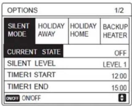
Use "ON/OFF" to select ON or OFF.
Description:
If CURRENT STATE is OFF, SILENT MODE is invalid.
When you select SILENT LEVEL, and press "OK" or "►".
The following page will appear:
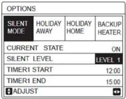
LEVEL 1
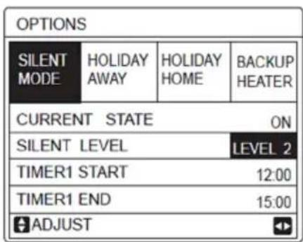
LEVEL 2
You can use "▼", "▲" to select level 1 or level 2.
Press "OK".
If the silent TIMER is selected, Press "OK" to enter, the following page will appear.
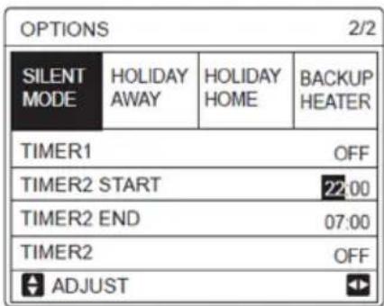
There are two timers for setting. Move to "■", press "OK" to select or unselect.
If the two time are both unselected, the silent mode will operate in all time. Otherwise, it will operate according as the time.
Holiday Away
If the holiday away mode is activated, will display on the home page.
The holiday away function is used to prevent frozen in the winter during the outside holiday, and return the unit before the end of the holiday.
Go to "MENU" > "OPTIONS" > "HOLIDAY AWAY".
Press "OK". The following page will appear:
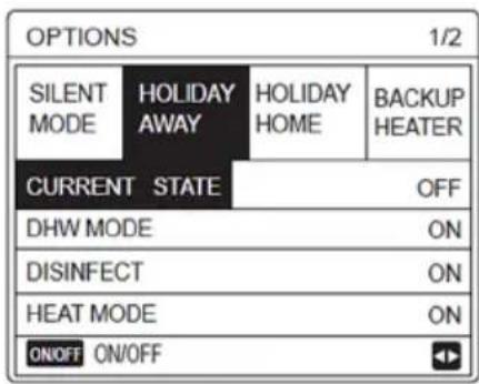
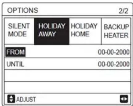
Usage example:
You go away during the winter.
The current date is 2018-01-31, two days later is 2018-02-02, it is the beginning date of the holiday.
If you are in the following situation:
In 2 days, you go away for 2 weeks during the winter.
You want to save energy, but prevent your house from freezing.
Then you can do the following:
1) Configure the holiday away the following settings:
2) Activate the holiday mode.
Go to "MENU" > "OPTIONS" > "HOLIDAY AWAY".
Press "OK".
Use "ON/OFF" to select "OFF" or "ON" and use "◀", "▶", "▼", "▲" to scroll and adjust.
| Setting | Value |
| Holiday Away | ON |
| From | 2 February 2018 |
| Until | 16 February 2018 |
| Operation Mode | Heating |
| Disinfect ON |
i INFORMATION
If DHW mode in holiday away mode is ON, The disinfect set by user is invalid.
If holiday away mode is ON, The timer and weekly schedule are invalid except exit.
If the CURRENT STATE is OFF, the HOLIDAY AWAY is OFF.
If the CURRENT STATE is ON, the HOLIDAY AWAY is ON.
The remote control doesn't accept any orders when holiday away mode is ON.
i INFORMATION
Disinfecting the unit on 23:00 of the last day if disinfect is ON.
When in holiday away mode, the climate related curves previously set is invalid, and the curves will automatically take effect after the holiday away mode is ends.
The preset temperature is invalid when in holiday away mode, but the preset value still display on the main page.
Holiday Home
The holiday home function is used to deviate from the normal schedules without having to change them during the holiday at home.
During your holiday, you can use the holiday mode to deviate from your normal schedules without having to change them.
| Period | Value |
| Before and after your holiday | Your normal schedules will be used |
| During your holiday | The configured holiday settings will be used |
If the holiday home mode is activated, will display on the home page.
Go to "MENU" > "OPTIONS" > "HOLIDAY HOME".
Press "OK".
The following page will appear:
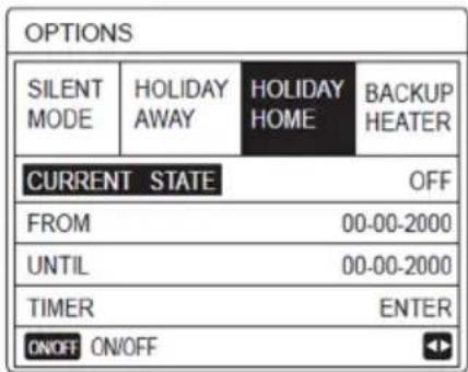
Use "ON/OFF" to select "OFF" or "ON" and use "◀", "▶", "▼", "▲" to scroll and adjust.
If the CURRENT STATE is OFF, the HOLIDAY HOME is OFF.
If the CURRENT STATE is ON, the HOLIDAY HOME is ON.
Use "▼", "▲" to adjust the date.
Before and after your holiday, your normal schedule will be used.
During your holiday, you save energy and prevent your house from freezing.
i INFORMATION
You have to reset Holiday away or Holiday home, if you change the operation mode of the unit.
Beckup Heater
The BACKUP HEATER function is used to force the backup heater. Go to "MENU" > "OPTIONS" > "BACKUP HEATER".
Press "OK".
If IBH and AHS is set invalid by DIP switch on the main control board of hydraulic module. The following page will appear.
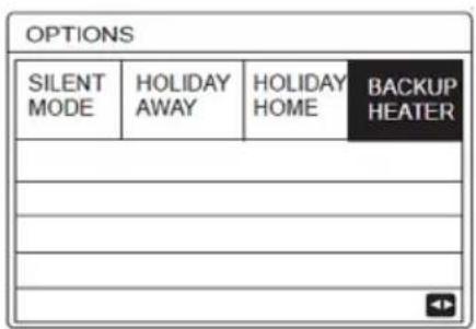
IBH = Indoor unit backup heater.
AHS = Additional heating source.
If IBH and AHS is set valid by DIP switch on the main control board of hydraulic module, the following page will appear:
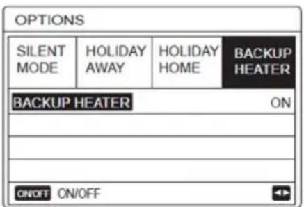
Use "ON/OFF" to select "OFF" or "ON".
i INFORMATION
If the operation mode is auto mode in space heating or cooling side, the buckup heater function can not be selected.
The BACKUP HEATER function is invalid when only ROOM HEAT MODE enabled.
Child Lock
The CHILD Lock function is used to prevent children error operation. The mode setting and temperature adjusting can be locked or unlocked by using CHILD LOCK function.
The page is displayed:
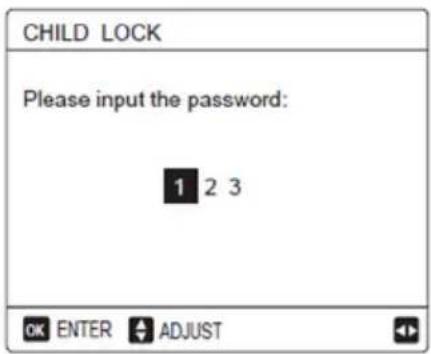
Input the corrent password, the following page will appear:
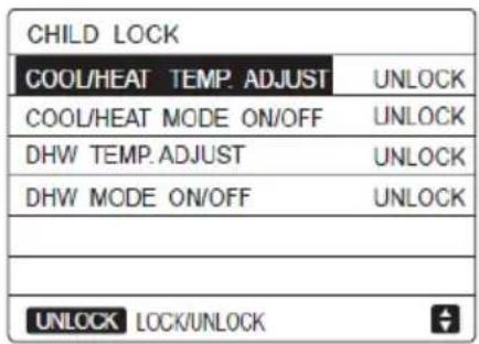
Use "▼"、"▲" to scroll and "ON/OFF" to select LOCK or UNLOCK.
The cool/heat temperature can't be adjusted when the COOL/HEAT TEMP. ADJUST is locked. If you want to adjust the cool/heat temperature when cool/heat temperature is locked, the following page will appear:
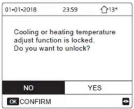
The Cool/Heat mode can't turn ON or OFF when the COOL/HEAT MODE ON/OFF is locked.
If you want to turn on or off the Cool/Heat mode when COOL/HEAT MODE ON/OFF is locked, the following page will appear:
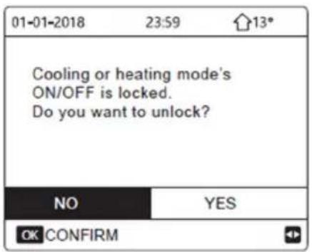
The DHW temperature can't be adjusted when the DHW TEMP. ADJUST is locked. If you want to adjust the DHW temperature when DHW TEMP. ADJUST is Locked, the following page will appear:
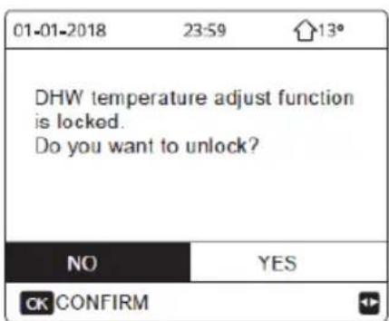
The DHW mode can't turn on or off when the DHW MODE ON/OFF is locked. If you want to turn ON or OFF the DHW mode when DHW MODE ON/OFF is Locked, the following page will appear:
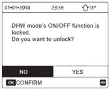
SERVICE INFORMATION
About service information
Service information menu contents as following:
1) SERVICE CALL
2) ERROR CODE
3) PARAMETER
4) DISPLAY
How to go to service information menu
Go to "MENU" > "SERVICE INFORMATION". Press "OK".
The following page will appear:
The service call can show the service phone or mobile member. The installer can input the phone number.
See "FOR SERVICEMAN".
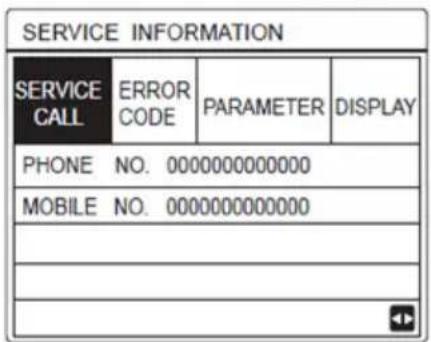
Error code is used to show when the fault or proction happen and show the mean of the error code.
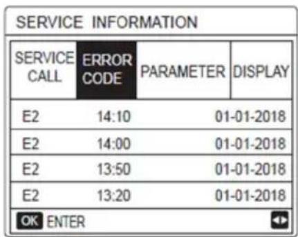
Press OK the page will appear:
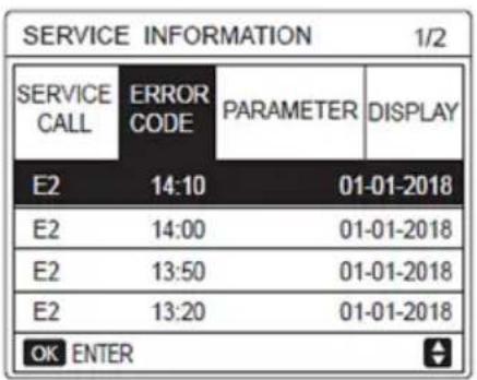
Press OK to show the mean of the error code:
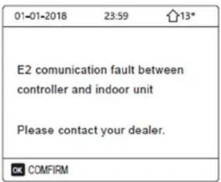
i INFORMATION
A total of eight fault codes can be recorded.
The parameter function is used to display the main parameter, there are two pages to show the parameter:
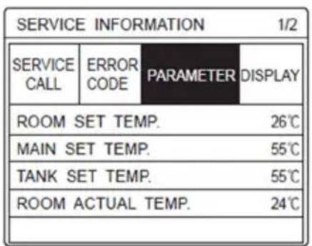
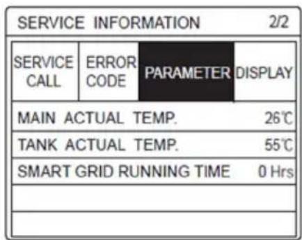
The DISPLAY function is used to set the interface:
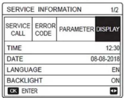
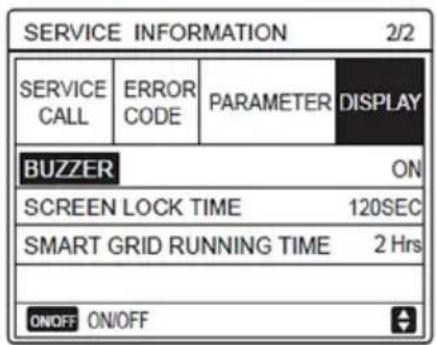
Use "OK" to enter and use "◀", "▶", "▼", "▲" to scroll.
Operation Parameter
This menu is for installer or service engineer reviewing the operation parameter.
At home page, go to "MENU" > "OPERATION PARAMETER".
Press "OK". There are six pages for the operating parameter as following.
Use "▼", "▲" to scroll.
| OPERATION PARAMETER | 1/6 |
| OPERATE MODE | COOL |
| CURRENT | 12 A |
| COMPRESSOR FREQUENCY | 24 Hz |
| COMP. RUN TIME1 | 54 MIN |
| COMP. RUN TIME2 | 65 MIN |
| COMP. RUN TIME3 | 10 MIN |
| OPERATION PARAMETER | 2/6 | |
| COMP.RUN TIME4 | 1000 HOUR | |
| EXPANSION VALVE | 240 P | |
| FAN SPEED | 600 R/MIN | |
| IDU TARGET FREQUENCY | 0 HZ | |
| FREQUENCY LIMITED TYPE | 0 | |
| T1 LEAVING WATER TEMP. | 25 °C | |
| + | ||
| OPERATION PARAMETER | 3/6 |
| T1B CIRCUIT2 WATER TEMP. | 30 °C |
| T2 PLATE F-OUT TEMP. | 30 °C |
| T2B PLATE F-IN TEMP. | 45 °C |
| T3 OUTDOOR EXCHANGE TEMP. | -7 °C |
| T4 OUTDOOR AIR TEMP. | -7 °C |
| T5 WATER TANK TEMP. | -7 °C |
| OPERATION PARAMETER | 4/6 |
| Ta ROOM TEMP. | 25 °C |
| Th COMP. SUCTION TEMP. | 25 °C |
| Tp COMP. DISCHARGE TEMP. | 25 °C |
| TW-O PLATE W-OUTLET TEMP. | 25 °C |
| TW-I PLATE W-INLET TEMP. | 25 °C |
| P1 COMP. PRESSURE1 | 200 kPa |
| OPERATION PARAMETER | 5/6 |
| T1S' C1 CLI. CURVE TEMP. | 25 °C |
| T1S2' C2 CLI. CURVE TEMP. | 25 °C |
| TF MODULE TEMP. | 55 °C |
| SUPPLY VOLTAGE | 230 V |
| POWER CONSUM. | 1000 KWh |
| DC GENERATRIX VOLTAGE | 420 V |
| OPERATION PARAMETER | 6/6 |
| DC GENERATRIX CURRENT | 18 A |
| WATER FLOW | 1.72 M3/H |
| HEAT PUMP CAPACTIY | 11.52 KW |
| HMI SOFTWARE | 00-00-2000V00 |
| IDU SOFTWARE | 00-00-2000V00 |
| ODU SOFTWARE | 00-00-2000V00 |
i INFORMATION
The power consumption parameter is optional.
if some parameter not be activated in the system, the parameter will show "--"
The heat pump capacity is for reference only, not used to judge the ability of the unit. The accuracy of sensor is ±1^ . The flow rates parameters are calculated according to the pump running parameters, the deviation is different at different flow rates, the maximum of deviation is 15%.
For Serviceman
About For Serviceman
FOR SERVICEMAN is used for installater and service engineer.
- Setting the function of equipment.
- Setting the parameters.
How To Go To For Serviceman
Go to "MENU" > "FOR SERVICEMAN".
Press "OK".
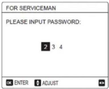
The FOR SERVICEMAN is used for installer or service engineer. It is NOT instended the home owner alters setting with this menu. It is for this reason password protection is requierd to prevent unauthorised access to the service settings.
The password is 2 3 4
How To Exit For SERVICEMAN
If you have set all the parameter.
Press "BACK", the following page will appear:
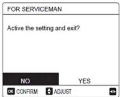
Select "YES" and press "OK" to exit the FOR SERVICEMAN.
After exiting the FOR SERVICEMAN, the unit will be Turned OFF.
Network Configuration Guidelines
The wired controller realizes intelligent control with a built-in module, which receives control signal from the APP.
Before connecting the WLAN, please check for it if the router in your environment is active and make sure that the wired controller is well-connected to the wireless signal.
During the Wireless distribution process, the LCD icon " [WiFi] "
flashes to indicate that the network is being deployed. After the process is completed, the icon " 🔍 " will be constantly on.
Wired Controller Setting
The wired controller settings include AP MODE and RESTORE WLAN SETTING.
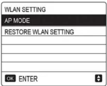
Activate the WLAN by interface.
Go to "MENU"> "WLAN SETTING"> "AP MODE".
Press "OK", the following page will appear:
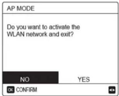
Use "◀", "▶" to move to "YES", press "OK" to select AP mode.
Select AP Mode correspondingly on the mobile device and continue the follow-up settings according to the APP prompts.

CAUTION
After enter Ap mode, if it's not connected with mobile phone, the LCD icon " 🔺 " will flash 10 minutes then disappear.
If it's connected with the mobile phone, the icon " 🔺 " will be constantly display.
Restore WLAN setting by interface.
Go to "MENU"> "WLAN SETTING" > "RESTORE WLAN SETTING".
Press "OK", the following page will appear:
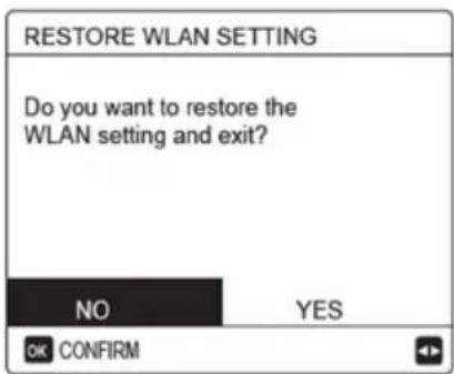
Use "◀" "▶" to move to "YES", press "OK" to restore WLAN setting.
Complete the above operation and wireless configuration is reset.
Mobile Device Setting
AP Mode is available for wireless distribution on mobile device side.
AP Mode connecting WLAN:
Install APP
- Scan the following QR code to install the Smart Home APP.

- Please research "Msmartlife" in APP STORE or GOOGLE PLAY to install the APP.
Sign in/Sign up
Click the "+" button on the right side of the home page, register account according to the guide.

Add Home Appliances:
- Choose the wired controller model, then go to add the device.
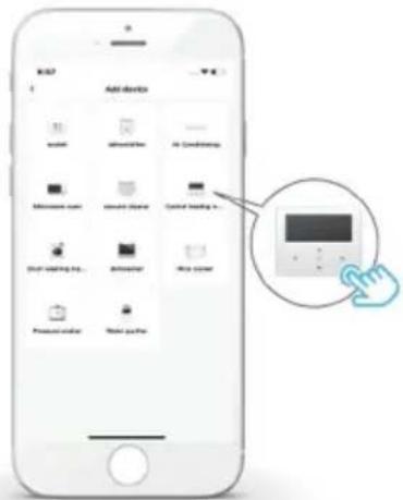
- Operate the wired controller according to APP prompts
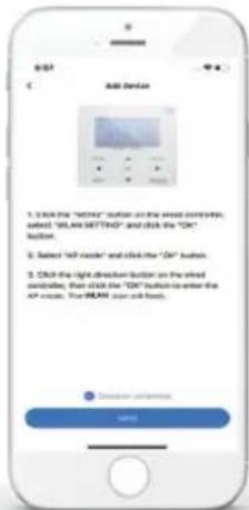
- Wait for the home appliance to connect, and click "Finish".

-
After the appliance is successfully connected, the LCD icon " 🔺 " of the wired controller is constantly On, and the air conditioner can be controlled through the APP.
-
If the network distribution process fails, or the mobile connection demands reconnection and replacement, operate "WLAN Factory Reset" on the wired controller, and then repeat the above process


Warning and trouble-shooting for networking failures
When the product is connected to the network, please make sure that the phone is as close as possible to the product.
We only support 2.4GHz band routers at present.
Special characters (punctuation, spaces, etc.) are not recommended as part of the WLAN name.
It is recommended that you connect no more than 10 devices to a single router lest home appliances are affected by weak or unstable network signal.
If the password of the router or WLAN is changed, clear all settings and reset the appliance.
The contents of APP might change in version updates and actual operation shall prevail.
MENU STRUCTURE : OVERVIEW
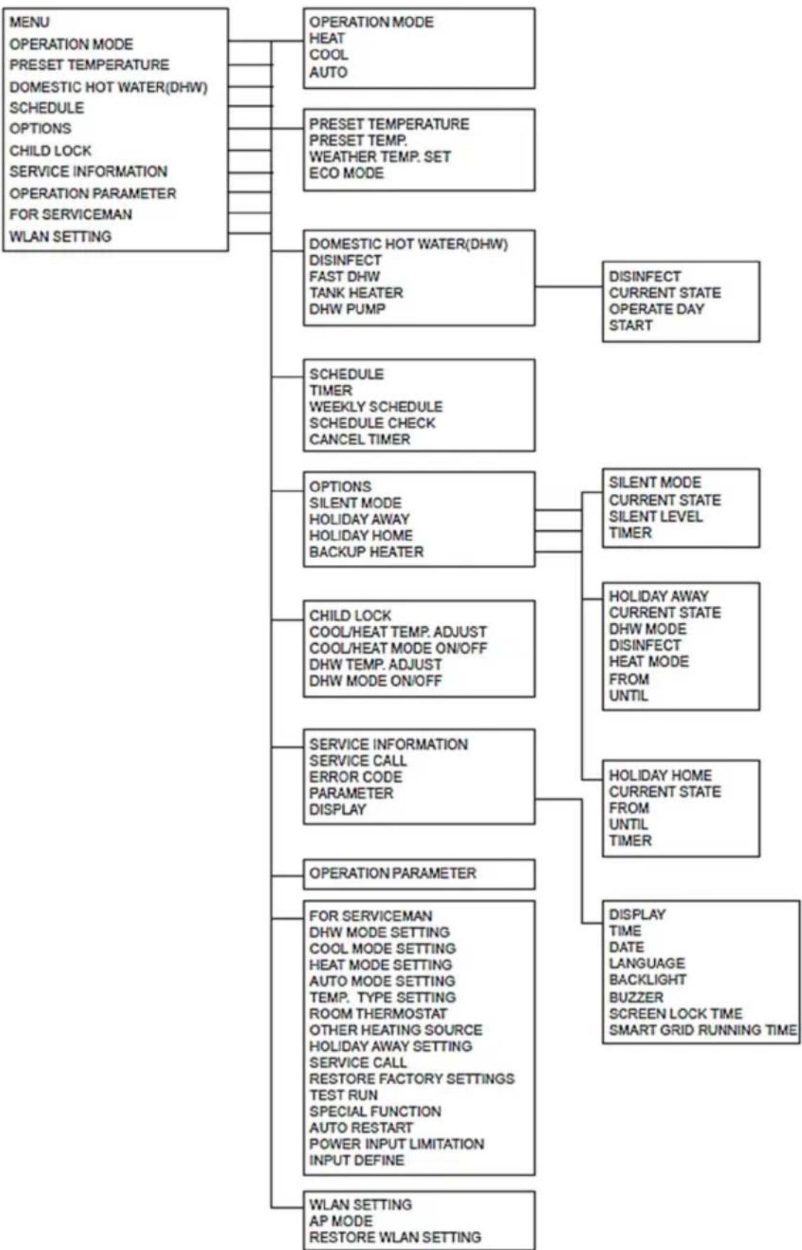
flowchart
graph TD
    A["MENU"] --> B["OPERATION MODE"]
    A --> C["PRESET TEMPERATURE"]
    A --> D["DOMESTIC HOT WATER(DHW)"]
    A --> E["SCHEDULE"]
    A --> F["OPTIONS"]
    A --> G["CHILD LOCK"]
    A --> H["SERVICE INFORMATION"]
    A --> I["OPERATION PARAMETER"]
    A --> J["FOR SERVICEMAN"]
    A --> K["WLAN SETTING"]

    B --> L["OPERATION MODE"]
    B --> M["HEAT"]
    B --> N["COOL"]
    B --> O["AUTO"]

    C --> P["PRESET TEMPERATURE"]
    C --> Q["PRESET TEMP."]
    C --> R["WEATHER TEMP. SET"]
    C --> S["ECO MODE"]

    D --> T["DOMESTIC HOT WATER(DHW)"]
    D --> U["DISINFECT"]
    D --> V["FAST DHW"]
    D --> W["TANK HEATER"]
    D --> X["DHW PUMP"]

    T --> Y["DISINFECT CURRENT STATE OPERATE DAY START"]

    E --> Z["SCHEDULE"]
    E --> AA["TIMER WEEKLY SCHEDULE SCHEDULE CHECK CANCEL TIMER"]

    F --> AB["OPTIONS"]
    F --> AC["SILENT MODE HOLIDAY AWAY HOLIDAY HOME BACKUP HEATER"]

    G --> AD["CHILD LOCK COOL/HEAT TEMP. ADJUST COOL/HEAT MODE ON/OFF DHW TEMP. ADJUST DHW MODE ON/OFF"]

    H --> AE["SERVICE INFORMATION SERVICE CALL ERROR CODE PARAMETER DISPLAY"]

    I --> AF["OPERATION PARAMETER"]

    J --> AG["FOR SERVICEMAN DHW MODE SETTING COOL MODE SETTING HEAT MODE SETTING AUTO MODE SETTING TEMP. TYPE SETTING ROOM THERMOSTAT OTHER HEATING SOURCE HOLIDAY AWAY SETTING SERVICE CALL RESTORE FACTORY SETTINGS TEST RUN SPECIAL FUNCTION AUTO RESTART POWER INPUT LIMITATION INPUT DEFINE"]

    K --> AH["WLAN SETTING AP MODE RESTORE WLAN SETTING"]

    subgraph Operation Settings
        I
        J
        K
    end

    subgraph Operation Parameters
        L
        M
        N
        O
        P
        Q
        R
        S
        T
        U
        V
        W
        X
        Y
        Z
        AA
        AB
        AC
        AD
        AE
        AF
        AG
        AH
    end

    subgraph Display Time
        I
        J
        K
        L
        M
        N
        O
        P
        Q
        R
        S
        T
        U
        V
        W
        X
        Y
        Z
    end

    subgraph Display Language
        I
        J
        K
        L
        M
        N
        O
        P
        Q
        R
        S
        T
        U
        V
        W
        X
    end

    subgraph Display BUZZER
        I
        J
        K
        L
        M
        N
        O
        P
        Q
        R
        S
        T
        U
        V
        W
    end

    subgraph Display GREEN LOCK TIME
        I
        J
        K
        L
        M
        N
        O
        P
        Q
        R
        S
        T
        U
        V
        W
    end

    subgraph Display SMART GRID RUNNING TIME
        I
        J
        K
        L
        M
        N
        O
        P
        Q
        R
        S
    end

    A --> B --> C --> D --> E --> F --> G --> H --> I --> J --> K --> L --> M --> N --> O --> P --> Q --> R --> S --> T --> U --> V --> W --> X --> Y --> Z --> AA --> AB --> AC --> AD --> AE --> AF --> AG --> AH --> AI --> AJ --> AK --> AL --> AM --> AN --> AO --> AP --> AQ --> AR --> AS --> AT --> AU --> AV --> AW --> AX --> AY --> AZ --> BA --> BB --> BC --> BD --> BE --> BF --> BG --> BH --> BI --> BJ --> BK --> BL --> BM --> BN --> BO --> BP --> BQ --> BY

    subgraph Operation Details
        I1["OPERATION MODE"]
        I2["HEAT"]
        I3["COOL"]
        I4["AUTO"]
    end

    subgraph Operation Parameters & Details
        B1["OPERATION MODE"]
    end

    subgraph Operation Settings & Details
        C1["PRESET TEMPERATURE"]
        C2["PRESET TEMP."]
        C3["WEATHER TEMP. SET"]
        C4["ECO MODE"]
    end

    subgraph Operation Details & Details & Details & Details & Details & Details & Details & Details & Details & Details & Details & Details & Details & Details & Details & Details & Details & Details & Details & Details & Details & Details & Details & Details & Details & Details & Details & Details & Details & Details & Details & Details & Details & Details & Details & Details & Details & Details & Details & Details & Details & Details & Details & Details & Details & Details & Details & Details & Details & Details & Details,
    end

    subgraph Operation Parameters & Details & Details & Details & Details & Details & Details & Details & Details & Details & Details & Details & Details & Details & Details & Details & Details & Details & Details & Details & Details & Details & Details & Details & Details & Details & Details & Details & Details & Details,
    end

    subgraph Operation Settings & Details & Details & Details & Details & Details & Details & Details & Details & Details & Details & Details & Details & Details & Details,
    end

    subgraph Operation Parameters & Details,
    I1["OPERATION MODE"]
    I2["HEAT"]
    I3["COOL"]
    I4["AUTO"]
    end

    subgraph Operation Settings,
    J1["OPERATION MODE"]
    J2["HEAT"]
    J3["COOL"]
    J4["AUTO"]
    J5["BEETHP. SET"]
    J6["ECO MODE"]

    subgraph Operation Parameters,
    K1["OPERATION MODE"]
    K2["HEAT"]
    K3["COOL"]
    K4["AUTO"]
    K5["BEETHP. SET"]
    K6["ECO MODE"]

    subgraph Operation Settings,
    L1["OPERATION MODE"]
    L2["HEAT"]
    L3["COOL"]
    L4["AUTO"]
    L5["BEETHP. SET"]
    L6["ECO MODE"]

    subgraph Operation Parameters,
    M1["OPERATION MODE"]
    M2["HEAT"]
    M3["COOL"]
    M4["AUTO"]
    M5["BEETHP. SET"]
    M6["ECO MODE"]

    subgraph Operation Settings,
    N1["OPERATION MODE"]
    N2["HEAT"]
    N3["COOL"]
    N4["AUTO"]
    N5["BEETHP. SET"]
    N6["ECO MODE"]

    subgraph Operation Parameters,
    O1["OPERATION MODE"]
    O2["HEAT"]
    O3["COOL"]
    O4["AUTO"]
    O5["BEETHP. SET"]
    O6["ECO MODE"]

    subgraph Operation Settings,
    P1["OPERATION MODE"]
    P2["HEAT"]
    P3["COOL"]
    P4["AUTO"]
    P5["BEETHP. SET"]
    P6["ECO MODE"]

    subgraph Operation Parameters,
    Q1["OPERATION MODE"]
    Q2["HEAT"]
    Q3["COOL"]
    Q4["AUTO"]
    Q5["BEETHP. SET"]
    Q6["ECO MODE"]

    subgraph Operation Settings,
    R1["OPERATION MODE"]
    R2["HEAT"]
    R3["COOL"]
    R4["AUTO"]
    R5["BEETHP. SET"]
    R6["ECO MODE"]

    subgraph Operation Parameters,
    S1["OPERATION MODE"]
    S2["HEAT"]
    S3["COOL"]
    S4["AUTO"]
    S5["BEETHP. SET"]
    S6["ECO MODE"]

    subgraph Operation Settings,
    T1["OPERATION MODE"]
    T2["HEAT"]
    T3["COOL"]
    T4["AUTO"]
    T5["BEETHP. SET"]
    T6["ECO MODE"]

    subgraph Operation Parameters,
    U1["OPERATION MODE"]
    U2["HEAT"]
    U3["COOL"]
    U4["AUTO"]
    U5["BEETHP. SET"]
    U6["ECO MODE"]

    subgraph Operation Settings,
    V1["OPERATION MODE"]
    V2["HEAT"]
    V3["COOL"]
    V4["AUTO"]
    V5["BEETHP. SET"]
    V6["ECO MODE"]

    subgraph Operation Parameters,
    W1["OPERATION MODE"]
    W2["HEAT"]
    W3["COOL"]
    W4["AUTO"]
    W5["BEETHP. SET"]
    W6["ECO MODE"]

    subgraph Operation Settings,
    X1["OPERATION MODE"]
    X2["HEAT"]
    X3["COOL"]
    X4["AUTO"]
    X5["BEETHP. SET"]
    X6["ECO MODE"]

    subgraph Operation Parameters,
    Y1["OPERATION MODE"]
    Y2["HEAT"]
    Y3["COOL"]
    Y4["AUTO"]
    Y5["BEETHP. SET"]
    Y6["ECO MODE"]

    subgraph Operation Settings,
    Z1["OPERATION MODE"]
    Z2["HEAT"]
    Z3["COOL"]
    Z4["AUTO"]

    subgraph Operation Parameters,
    AA1["OPERATION MODE"]
    AA2["HEAT"]
    AA3["COOL"]

    end
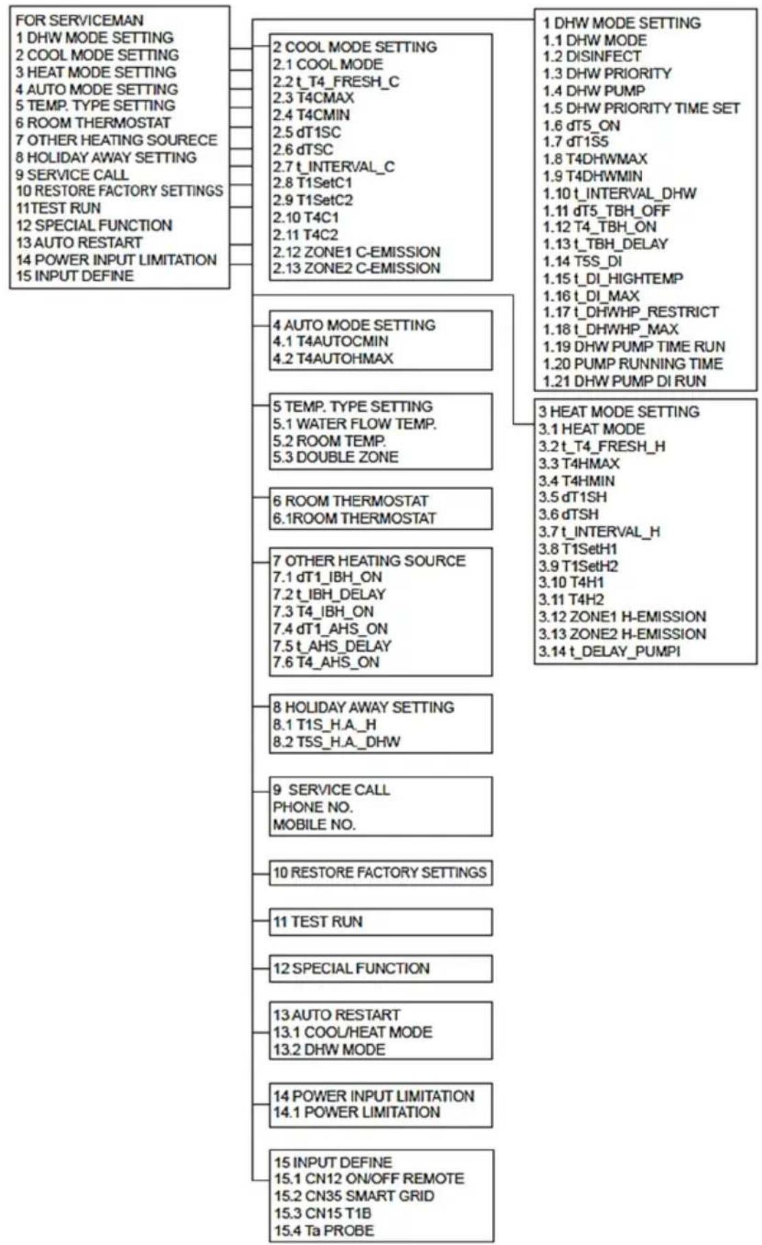
flowchart
graph TD
    A["FOR SERVICEMAN\n1 DHW MODE SETTING\n2 COOL MODE SETTING\n3 HEAT MODE SETTING\n4 AUTO MODE SETTING\n5 TEMP. TYPE SETTING\n6 ROOM THERMOSTAT\n7 OTHER HEATING SOURCE\n8 HOLIDAY AWAY SETTING\n9 SERVICE CALL\n10 RESTORE FACTORY SETTINGS\n11 TEST RUN\n12 SPECIAL FUNCTION\n13 AUTO RESTART\n14 POWER INPUT LIMITATION\n15 INPUT DEFINE"] --> B["2 COOL MODE SETTING\n2.1 COOL MODE\n2.2 t_T4_FRESH_C\n2.3 T4CMAX\n2.4 T4CMIN\n2.5 dT1SC\n2.6 dTSC\n2.7 t_INTERVAL_C\n2.8 T1SetC1\n2.9 T1SetC2\n2.10 T4C1\n2.11 T4C2\n2.12 ZONE1 C-EMISSION\n2.13 ZONE2 C-EMISSION"]
    A --> C["4 AUTO MODE SETTING\n4.1 T4AUTOCMIN\n4.2 T4AUTOHMAX"]
    A --> D["5 TEMP. TYPE SETTING\n5.1 WATER FLOW TEMP.\n5.2 ROOM TEMP.\n5.3 DOUBLE ZONE"]
    A --> E["6 ROOM THERMOSTAT\n6.1ROOM THERMOSTAT"]
    A --> F["7 OTHER HEATING SOURCE\n7.1 dT1_IBH_ON\n7.2 t_IBH_DELAY\n7.3 T4_IBH_ON\n7.4 dT1_AHS_ON\n7.5 t_AHS_DELAY\n7.6 T4_AHS_ON"]
    A --> G["8 HOLIDAY AWAY SETTING\n8.1 T1S_H.A_H\n8.2 T5S_H.A_DHW"]
    A --> H["9 SERVICE CALL\nPHONE NO.\nMOBILE NO."]
    A --> I["10 RESTORE FACTORY SETTINGS"]
    A --> J["11 TEST RUN"]
    A --> K["12 SPECIAL FUNCTION"]
    A --> L["13 AUTO RESTART\n13.1 COOL/HEAT MODE\n13.2 DHW MODE"]
    A --> M["14 POWER INPUT LIMITATION\n14.1 POWER LIMITATION"]
    A --> N["15 INPUT DEFINE\n15.1 CN12 ON/OFF REMOTE\n15.2 CN35 SMART GRID\n15.3 CN15 T1B\n15.4 Ta PROBE"]
    A --> O["1 DHW MODE SETTING\n1.1 DHW MODE\n1.2 DISINFECT\n1.3 DHW PRIORITY\n1.4 DHW PUMP\n1.5 DHW PRIORITY TIME SET\n1.6 dT5_ON\n1.7 dT1S5\n1.8 T4DHWMAX\n1.9 T4DHWMIN\n1.10 t_INTERVAL_DHW\n1.11 dT5_TBH_OFF\n1.12 T4_TBH_ON\n1.13 t_TBH_DELAY\n1.14 T5S_DI\n1.15 t_DI_HIGHTEMP\n1.16 t_DI_MAX\n1.17 t_DHWHP_RESTRICT\n1.18 t_DHWHP_MAX\n1.19 DHW PUMP TIME RUN\n1.20 PUMP RUNNING TIME\n1.21 DHW PUMP DI RUN"]
    A --> P["3 HEAT MODE SETTING\n3.1 HEAT MODE\n3.2 t_T4_FRESH_H\n3.3 T4HMAX\n3.4 T4HMIN\n3.5 dT1SH\n3.6 dTSH\n3.7 t_INTERVAL_H\n3.8 T1SetH1\n3.9 T1SetH2\n3.10 T4H1\n3.11 T4H2\n3.12 ZONE1 H-EMISSION\n3.13 ZONE2 H-EMISSION\n3.14 t_DELAY_PUMPI"]
Table 1: The environment temperature curve of the low temperature setting for heating
| T4 | ≤ -20 | -19 | -18 | -17 | -16 | -15 | -14 | -13 | -12 | -11 | -10 | -9 | -8 | -7 | -6 | -5 | -4 | -3 | -2 | -1 | 0 |
| 1-T1S | 38 | 38 | 38 | 38 | 38 | 37 | 37 | 37 | 37 | 37 | 37 | 36 | 36 | 36 | 36 | 36 | 36 | 35 | 35 | 35 | 35 |
| 2-T1S | 37 | 37 | 37 | 37 | 37 | 36 | 36 | 36 | 36 | 36 | 36 | 35 | 35 | 35 | 35 | 35 | 35 | 34 | 34 | 34 | 34 |
| 3-T1S | 36 | 36 | 36 | 35 | 35 | 35 | 35 | 35 | 35 | 34 | 34 | 34 | 34 | 34 | 34 | 33 | 33 | 33 | 33 | 33 | 33 |
| 4-T1S | 35 | 35 | 35 | 34 | 34 | 34 | 34 | 34 | 34 | 33 | 33 | 33 | 33 | 33 | 33 | 32 | 32 | 32 | 32 | 32 | 32 |
| 5-T1S | 34 | 34 | 34 | 33 | 33 | 33 | 33 | 33 | 33 | 32 | 32 | 32 | 32 | 32 | 32 | 31 | 31 | 31 | 31 | 31 | 31 |
| 6-T1S | 32 | 32 | 32 | 32 | 31 | 31 | 31 | 31 | 31 | 31 | 31 | 31 | 30 | 30 | 30 | 30 | 30 | 30 | 30 | 30 | 29 |
| 7-T1S | 31 | 31 | 31 | 31 | 30 | 30 | 30 | 30 | 30 | 30 | 30 | 30 | 29 | 29 | 29 | 29 | 29 | 29 | 29 | 29 | 28 |
| 8-T1S | 29 | 29 | 29 | 29 | 28 | 28 | 28 | 28 | 28 | 28 | 28 | 28 | 27 | 27 | 27 | 27 | 27 | 27 | 27 | 27 | 26 |
| T4 | 1 | 2 | 3 | 4 | 5 | 6 | 7 | 8 | 9 | 10 | 11 | 12 | 13 | 14 | 15 | 16 | 17 | 18 | 19 | ≥ 20 | |
| 1-T1S | 35 | 35 | 34 | 34 | 34 | 34 | 34 | 34 | 33 | 33 | 33 | 33 | 33 | 33 | 32 | 32 | 32 | 32 | 32 | 32 | 32 |
| 2-T1S | 34 | 34 | 33 | 33 | 33 | 33 | 33 | 33 | 32 | 32 | 32 | 32 | 32 | 32 | 31 | 31 | 31 | 31 | 31 | 31 | 31 |
| 3-T1S | 32 | 32 | 32 | 32 | 32 | 32 | 31 | 31 | 31 | 31 | 31 | 31 | 30 | 30 | 30 | 30 | 30 | 30 | 29 | 29 | 29 |
| 4-T1S | 31 | 31 | 31 | 31 | 31 | 31 | 30 | 30 | 30 | 30 | 30 | 30 | 29 | 29 | 29 | 29 | 29 | 29 | 28 | 28 | 28 |
| 5-T1S | 30 | 30 | 30 | 30 | 30 | 30 | 29 | 29 | 29 | 29 | 29 | 29 | 28 | 28 | 28 | 28 | 28 | 28 | 27 | 27 | 27 |
| 6-T1S | 29 | 29 | 29 | 29 | 29 | 29 | 28 | 28 | 28 | 28 | 28 | 28 | 27 | 27 | 27 | 27 | 27 | 27 | 26 | 26 | 26 |
| 7-T1S | 28 | 28 | 28 | 28 | 28 | 28 | 27 | 27 | 27 | 27 | 27 | 27 | 26 | 26 | 26 | 26 | 26 | 26 | 25 | 25 | 25 |
| 8-T1S | 26 | 26 | 26 | 26 | 26 | 26 | 26 | 25 | 25 | 25 | 25 | 25 | 25 | 25 | 25 | 24 | 24 | 24 | 24 | 24 | 24 |
Table 2: The environment temperature curve of the high temperature setting for heating
| T4 | ≤ -20 | -19 | -18 | -17 | -16 | -15 | -14 | -13 | -12 | -11 | -10 | -9 | -8 | -7 | -6 | -5 | -4 | -3 | -2 | -1 | 0 |
| 1-T1S | 55 | 55 | 55 | 55 | 54 | 54 | 54 | 54 | 54 | 54 | 54 | 54 | 53 | 53 | 53 | 53 | 53 | 53 | 53 | 53 | 52 |
| 2-T1S | 53 | 53 | 53 | 53 | 52 | 52 | 52 | 52 | 52 | 52 | 52 | 52 | 51 | 51 | 51 | 51 | 51 | 51 | 51 | 51 | 50 |
| 3-T1S | 52 | 52 | 52 | 52 | 51 | 51 | 51 | 51 | 51 | 51 | 51 | 51 | 50 | 50 | 50 | 50 | 50 | 50 | 50 | 50 | 49 |
| 4-T1S | 50 | 50 | 50 | 50 | 49 | 49 | 49 | 49 | 49 | 49 | 49 | 49 | 48 | 48 | 48 | 48 | 48 | 48 | 48 | 48 | 47 |
| 5-T1S | 48 | 48 | 48 | 48 | 47 | 47 | 47 | 47 | 47 | 47 | 47 | 47 | 46 | 46 | 46 | 46 | 46 | 46 | 46 | 46 | 45 |
| 6-T1S | 45 | 45 | 45 | 45 | 44 | 44 | 44 | 44 | 44 | 44 | 44 | 44 | 43 | 43 | 43 | 43 | 43 | 43 | 43 | 43 | 42 |
| 7-T1S | 43 | 43 | 43 | 43 | 42 | 42 | 42 | 42 | 42 | 42 | 42 | 42 | 41 | 41 | 41 | 41 | 41 | 41 | 41 | 41 | 40 |
| 8-T1S | 40 | 40 | 40 | 40 | 39 | 39 | 39 | 39 | 39 | 39 | 39 | 39 | 38 | 38 | 38 | 38 | 38 | 38 | 38 | 38 | 37 |
| T4 | 1 | 2 | 3 | 4 | 5 | 6 | 7 | 8 | 9 | 10 | 11 | 12 | 13 | 14 | 15 | 16 | 17 | 18 | 19 | ≥ 20 | |
| 1-T1S | 52 | 52 | 52 | 52 | 52 | 52 | 52 | 51 | 51 | 51 | 51 | 51 | 51 | 51 | 51 | 50 | 50 | 50 | 50 | 50 | 50 |
| 2-T1S | 50 | 50 | 50 | 50 | 50 | 50 | 50 | 49 | 49 | 49 | 49 | 49 | 49 | 49 | 49 | 48 | 48 | 48 | 48 | 48 | 48 |
| 3-T1S | 49 | 49 | 49 | 49 | 49 | 49 | 49 | 48 | 48 | 48 | 48 | 48 | 48 | 48 | 48 | 47 | 47 | 47 | 47 | 47 | 47 |
| 4-T1S | 47 | 47 | 47 | 47 | 47 | 47 | 47 | 46 | 46 | 46 | 46 | 46 | 46 | 46 | 46 | 45 | 45 | 45 | 45 | 45 | 45 |
| 5-T1S | 45 | 45 | 45 | 45 | 45 | 45 | 45 | 44 | 44 | 44 | 44 | 44 | 44 | 44 | 44 | 43 | 43 | 43 | 43 | 43 | 43 |
| 6-T1S | 42 | 42 | 42 | 42 | 42 | 42 | 42 | 41 | 41 | 41 | 41 | 41 | 41 | 41 | 41 | 40 | 40 | 40 | 40 | 40 | 40 |
| 7-T1S | 40 | 40 | 40 | 40 | 40 | 40 | 40 | 39 | 39 | 39 | 39 | 39 | 39 | 39 | 39 | 38 | 38 | 38 | 38 | 38 | 38 |
| 8-T1S | 37 | 37 | 37 | 37 | 37 | 37 | 37 | 36 | 36 | 36 | 36 | 36 | 36 | 36 | 36 | 35 | 35 | 35 | 35 | 35 | 35 |
The automatic setting curve
The automatic setting curve is the ninth curve, this is the calculation:
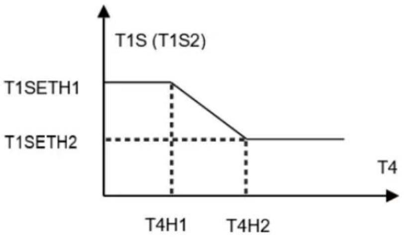
line
| Time Point | T1S (T1S2) | | ---------- | ---------- | | T4H1 | T1SETH1 | | T4H2 | T1SETH2 |State: In the setting the wired controller, if T4H2<T4H1, then exchange their value; if T1SETH1<T1SETH2, then exchange their value.
Table 3: The environment temperature curve of the low temperature setting for cooling
| T4 | -10≤ T4<15 | 15≤ T4<22 | 22≤ T4<30 | 30≤ T4 |
| 1-T1S | 16 | 11 | 8 | 5 |
| 2-T1S | 17 | 12 | 9 | 6 |
| 3-T1S | 18 | 13 | 10 | 7 |
| 4-T1S | 19 | 14 | 11 | 8 |
| 5-T1S | 20 | 15 | 12 | 9 |
| 6-T1S | 21 | 16 | 13 | 10 |
| 7-T1S | 22 | 17 | 14 | 11 |
| 8-T1S | 23 | 18 | 15 | 12 |
Table 4: The environment temperature curve of the high temperature setting for cooling
| T4 | -10≤ T4<15 | 15≤ T4<22 | 22≤ T4<30 | 30≤ T4 |
| 1-T1S | 20 | 18 | 17 | 16 |
| 2-T1S | 21 | 19 | 18 | 17 |
| 3-T1S | 22 | 20 | 19 | 17 |
| 4-T1S | 23 | 21 | 19 | 18 |
| 5-T1S | 24 | 21 | 20 | 18 |
| 6-T1S | 24 | 22 | 20 | 19 |
| 7-T1S | 25 | 22 | 21 | 19 |
| 8-T1S | 25 | 23 | 21 | 20 |
The automatic setting curve
The automatic setting curve is the ninth curve, this is the calculation
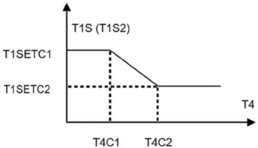
line
| Time Point | T1SETC1 | T1SETC2 | | ---------- | ------- | ------- | | T4C1 | High | Low | | T4C2 | Low | Low |State: In the setting the wired controller, if T4C2<T4C1, then exchange their value; if T1SETC1<T1SETC2, then exchange their value.
DISPOSAL OF ELECTRICAL AND ELECTRONIC EQUIPMENT
To protect our environment and to recycle the raw materials used as completely as possible, the consumer is asked to return unserviceable equipment to the public collection system for electrical and electronic.
The symbol of the crossed indicates that this product must be returned to the collection point for electronic waste to feed it by recycling the best possible raw material recycling.
By ensuring this product you will prevent possible negative effects on the environment and human health, which could otherwise be caused due to improper disposal of that product. The recycling of materials from this product, you will help to preserve a healthy environment and natural resources.
For detailed information about the collection of EE products contact the dealer where you purchased the product.
EU DECLARATON OF CONFORMITY
This device is manufactured in accordance with the applicable European standards and in accordance with all applicable Directives and Regulations.
EU declaration of conformity can be downloaded from the following link: www.msan.hr/dokumentacijaartikala

POŠTOVANI!
Zahvaljujemo na kupnji Vivax uređaja i nadamo se da ćete biti zadovoljni odabirom. Ako u jamstvenom roku bude potreban popravak proizvoda, molimo savjetujte se sa ovlaštenim prodavačem koji Vam je proizvod prodao ili nas kontaktirajte na dolje navedene brojeve i adrese. MOLIMO VAS DA PRIJE UPORABE PROIZVODA PAŽLJIVO PROČITATE UPUTE PR ILOŽENE UZ PROIZVOD!
JAMSTVENI LISTHR
VIVAX
MODEL UREĐAJA
SERIJSKI BROJ
DATUM PRODAJE
BROJ RAČUNA PRODAVATELJA
POTPIS I PEČAT PRODAVATELJA
BROJ RAČUNA PRODAVAOCA
POTPIS I PEČAT PRODAVAOCA
-
Preuzimamo obavezu besplatno popraviti ili zamijeniti neispravne dijelove Vivax cool klima uređaja koji bi se takvim pokazali za vrijeme trajanja garancije, kao greška prilikom izrade ili montaže Ovom garancijom garantiramo da će predmet ovog jamstva raditi bez pogreške uzrokovane eventualnom lošom izradom ili lošim materijalom izrade. Svi, eventualno nastali, kvarovi biti će besplatno otklonjeni u ovlaštenom servisu u garantnom roku.
-
GARANTNI UVJETI Garancija na Vivax cool klima uređaje počinje teći od dana kupnje proizvoda i traje 12 mjeseci.
-
Garancija na uređaje u komercijalnoj uporabi produžuje se za šljedećih 12 mjeseci nakon izvršenja garantnog servisnog pregleda od strane ovlaštenog servisa.
-
Garancija se može produžavali ukupno dva puta, što u ukupnom trajanju može iznositi 36 mjeseci.
-
Garantni servisni pregled naplaćuje ovlašten« servis po cjeniku zastupnika KimTec d o.a'i ovjerava garantni list što dokazuje produženje i valjanost jamstva.
-
Garancija vrijedi ako su montaža ili servis Vivax cool klima uređaja obavljeni od strane ovlaštenog servisa kojeg je ovlastio zastupnik Kimtec d.o.o..
-
Vivax cool klima uređaj kao cjelinu čine unutarnja jedinica, instalacija i vanjska jedinica koji su pravilno odabrani i koji si međusobno odgovaraju po modelu i snazi.
-
U slučaju kvara na Vivax cool klima uređaju obvezujemo se da ćemo isti popraviti u najkraćem mogućem roku, a najkasnije u roku 45 dana, ako se Vivax cool klima uređaj ne može popraviti ili se ne popravi u roku od 45 dana, biti će zamijenjen novim. Ako popravak Vivax cool klima uređaja traje duže od 10 dana, garancija će sa produžiti za vrijeme trajanja popravka.
-
Garancija se priznaje samo uz račun o kupnji, te uz ovaj garantni list koji mora bili ispravno popunjen i ovjeren od strane prodavatelja, ovlaštenog montažera ili servisera.
-
Davaoc gar ancije osigurava servis i rezervne dijelova 7 godina od datuma kupnje Vivax cool klima uređaja
11. JAMSTVO NE OBUHVAĆA
POTPIS I PEČAT PRODAVCA
-
Ovom izjavom o saobraznosti proizvođač proizvoda, preko KIM TEC CG d.o.o., kao uvoznika i davaoca prava u Crnoj Gori osigurava besplatan popravak istog u skladu s vazečim propisima i u skladu s uslovima opisanim u ovoj izjavi o saobraznosti.
-
Ovom izjavom o saobraznosti ističemo da će predmet ovog prava raditi bez greške uzrokovane eventualnom lošom Izradom i lošim materijalom izrade. Svi eventualno nastali kvarovi biće besplatno otklonjeni u ovlašcenom servisu u predvidjenom roku za reklamaciju.
-
USLOVI REKLAMACIJE: Rok za reklamaciju počinje teći od dana kupovine proizvoda i traje 24 mjeseca. Dodatnih 12 mjeseci važi uz redovan godišnji servis.
-
U slučaju kvara na proizvodu koji je predmet reklamacije, obavezujemo se da ćemo isti popraviti u najkraćem mogućem roku, a najkasnije u roku od 15 dana. Ako se proizvod ne može popraviti ili se ne popravi u roku od 15 dana, biće zamijenjen novim.
-
Pravo na reklamaciju se priznaje uz fiskalni račun o kupovini, ili uz ovu izjavu o saobraznosti koji mora biti ispravno popunjen odnosno mora sadržati datum prodaje, pečat i potpis prodavca.
-
Davalac izjave o saobraznosti osigurava servis i rezervne djelove 7 godina od datuma kupovine.