
DP-102 - Sensor PANASONIC - Free user manual and instructions
Find the device manual for free DP-102 PANASONIC in PDF.

| Product Type | Digital Pressure Sensor |
| Model | DP-102 (High Pressure Type) |
| Rated Pressure Range | -0.100 to +1.000 MPa |
| Display | Dual 4-digit 3-color LCD (Red, Green, Orange) |
| Supply Voltage | 12 to 24 V DC ±10%, Ripple ≤10% |
| Power Consumption | Normal: ≤840 mW (35 mA at 24 V); ECO STD: ≤600 mW; ECO FULL: ≤480 mW |
| Output Type | NPN or PNP open-collector transistor, 100 mA max |
| Output Modes | EASY mode, Hysteresis mode, Window comparator mode |
| Response Time | Selectable: 2.5 ms to 5000 ms (10 levels) |
| Repeatability | ±0.1% F.S. |
| Temperature Characteristics | ±0.5% F.S. at +20°C |
| Hysteresis | Minimum 1 digit (variable), 2 digits for psi |
| External Input (Multi-function type) | Auto-reference / Remote zero-adjustment (0.4 V ON, 5-30 V OFF) |
| Analog Output (Multi-function type) | 1 to 5 V DC (low pressure), 0.6 to 5 V DC (high pressure) |
| Pressure Port | M5 female thread + R (PT) 1/8 male (Asian); G 1/8 (European); NPT 1/8 (N. American) |
| Enclosure Material | PBT (glass fiber reinforced), Acrylic display, Brass (nickel plated) port, Silicone keypad |
| Weight | Approx. 40 g (net), 135 g (gross including cable) |
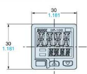
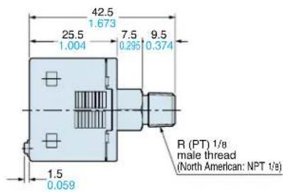
| Dimensions (W x H x D) | 30 mm x 30 mm x 42.5 mm (without mounting bracket) |
| Protection Rating | IP40 (IEC) |
| Ambient Temperature | -10 to +50°C (operation), -10 to +60°C (storage) |
| Accessories Included | Connector attached cable CN-14A-C2 (2 m) |
Frequently Asked Questions - DP-102 PANASONIC
User questions about DP-102 PANASONIC
0 question about this device. Answer the ones you know or ask your own.
Ask a new question about this device
Download the instructions for your Sensor in PDF format for free! Find your manual DP-102 - PANASONIC and take your electronic device back in hand. On this page are published all the documents necessary for the use of your device. DP-102 by PANASONIC.
USER MANUAL DP-102 PANASONIC
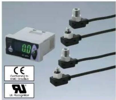
DIGITAL PRESSURE SENSOR
New DP-100 SERIES


A New Global Standard
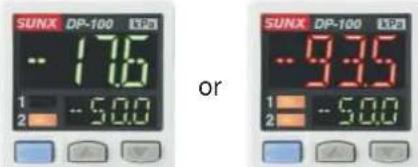
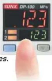
Dual display for the digital pressure sensors of the future
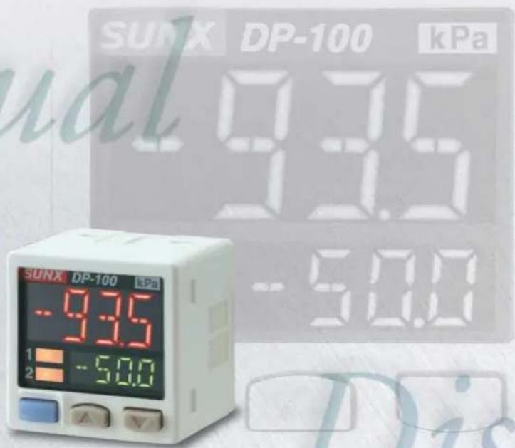
Industry first.\* Dual 3-color display makes operation easier!
The dual display means that the ‘current value’ and the ‘threshold value’ can be displayed at the same time to improve ease of operation and visual checking.
Introducing a new standard in digital pressure sensor technology.
※ As of November 2005 and based on research conducted by SUNX for 30 mm 1.181 in square sized digital pressure sensors.
A new global standard
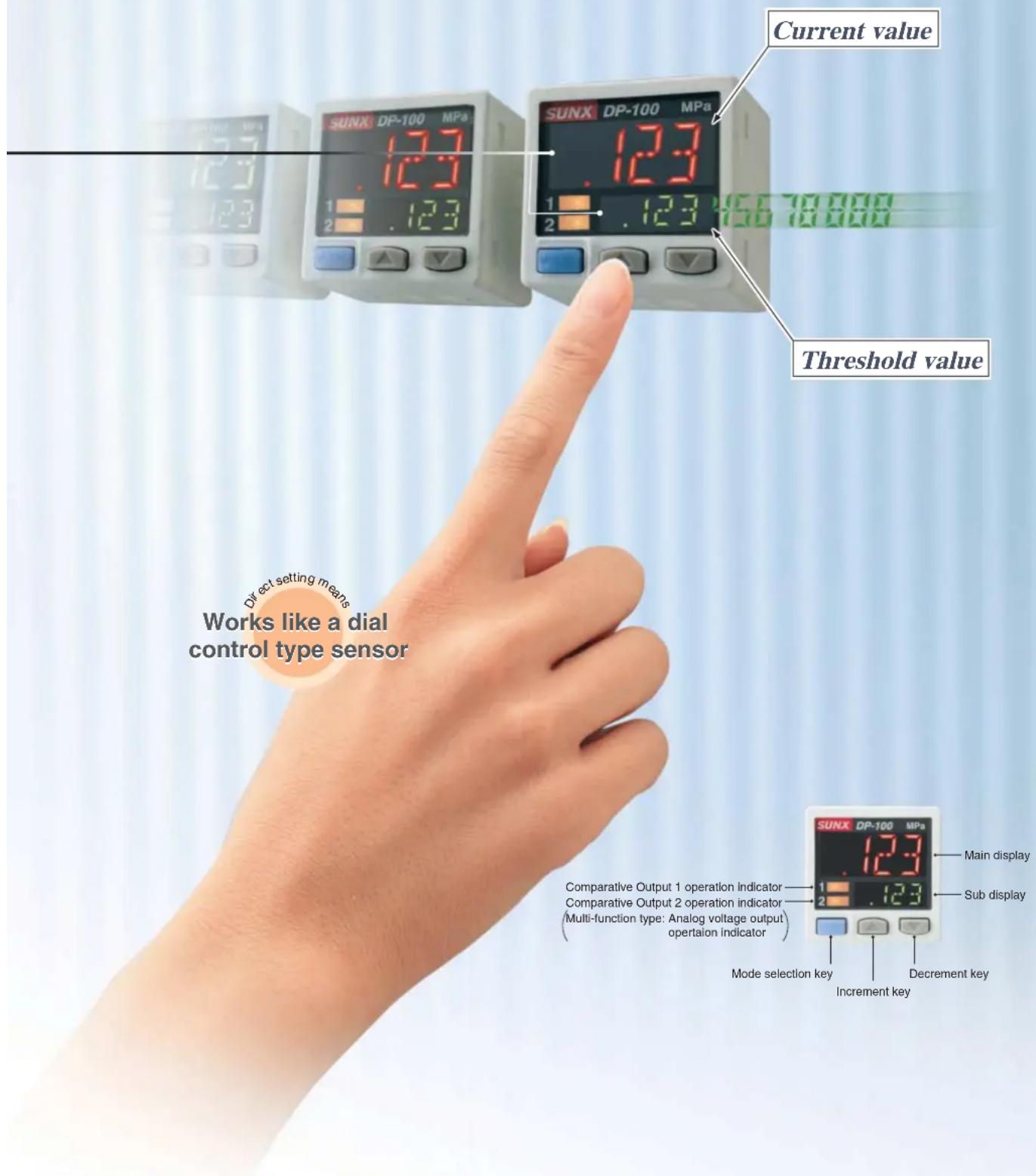
'Current value' and 'threshold value' can be checked at the same time!
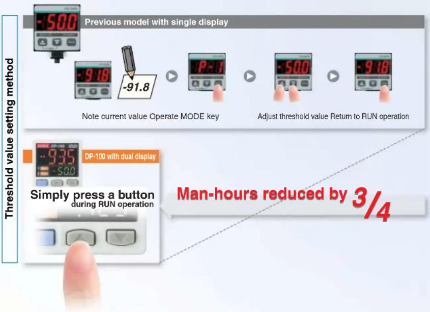
Dual display allows direct setting of threshold value
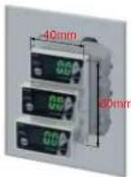
Equipped with a 30 mm 1.181 in square compact-sized dual display. Because the current value and the threshold value can be checked at the same time, the threshold value can be set and checked smoothly without having to switch screen modes. ON / OFF operations are still carried out while the threshold values are being set, so setting to the same sensitivity as dial control-type sensors is possible. And naturally a key lock function is also equipped.
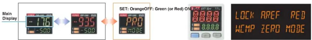
3-color display (Red, Green, Orange)
The main display changes color in line with changes in the status of output ON / OFF operation, and it also changes color while setting is in progress. The sensor status can therefore be understood easily, and operating errors can be reduced.
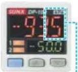
Readable digital display!
12 segments are used and an alphanumeric display has been adopted. This improves visual checking of letters and numbers.
During normal operation During setting
Dual Display
+
Direct setting
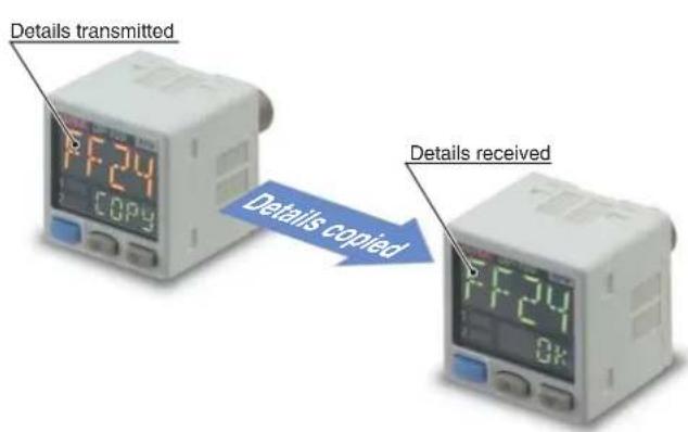
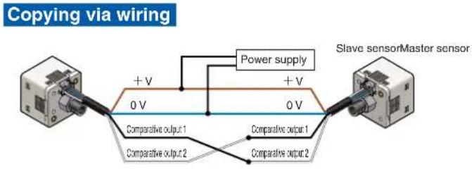
Copy function lets work be carried out accurately and quickly
Copy function reduces man-hours and human error
Sensors can be connected to a master sensor one by one, and a copy of the setting details for the master sensor can be transmitted as data to the other sensors. If making the same settings for multiple sensors, this prevents setting errors from occurring with the other sensors and also reduces the number of changes required to instruction manuals when equipment designs are changed.
Setting details can be copied.
Advantage
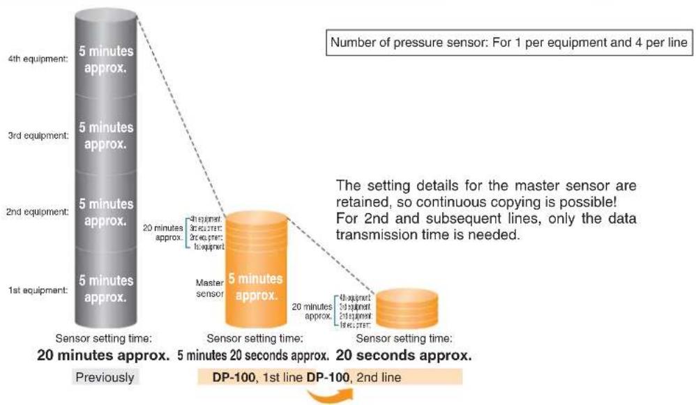
1 Setting man-hours are reduced and sensor setting time is shortened.
bar
| Sensor Setting | Approx. Time (minutes) | Approx. Time (seconds) | |---|---|---| | 1st equipment | 5 | 20 | | 2nd equipment | 5 | 20 | | 3rd equipment | 5 | 20 | | 4th equipment | 5 | 20 | The setting details for the master sensor are retained, so continuous copying is possible! For 2nd and subsequent lines, only the data transmission time is needed. DP-100, 1st line DP-100, 2nd line.Advantage
2 Human operating error is reduced.
● Because all details are copied automatically, it prevents problems occurring as a result of human error.
- Instruction manuals can be updated easily when changes occur to equipment design!
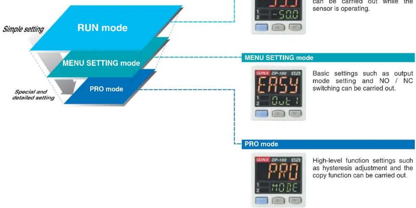
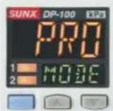
Setting is smooth and easy
The sensor's setting operation mode has a 3-level configuration to suit the frequency of use.
The setting levels are clearly separated into 'RUN mode' for operation settings that are carried out daily, 'MENU SETTING mode' for basic settings, and 'PRO mode' for special and detailed setting. These make setting operations easy to understand and easy to carry out.
flowchart
graph TD
    A["Simple setting"] --> B["RUN mode"]
    C["MENU SETTING mode"] --> D["PRO mode"]
    E["Special and detailed setting"] --> F["PRO mode"]
    G["PRO mode"] --> H["SUNX DP-100 120"]
    I["PRO mode"] --> J["SUNX DP-100 120"]
    K["PRO mode"] --> L["SUNX DP-100 120"]
    M["PRO mode"] --> N["SUNX DP-100 120"]
    O["PRO mode"] --> P["SUNX DP-100 120"]
    Q["PRO mode"] --> R["SUNX DP-100 120"]
    S["PRO mode"] --> T["SUNX DP-100 120"]
    U["PRO mode"] --> V["SUNX DP-100 120"]
    W["PRO mode"] --> X["SUNX DP-100 120"]
    Y["PRO mode"] --> Z["SUNX DP-100 120"]
    AA["PRO mode"] --> AB["SUNX DP-100 120"]
    AC["PRO mode"] --> AD["SUNX DP-100 120"]
    AE["PRO mode"] --> AF["SUNX DP-100 120"]
    AG["PRO mode"] --> AH["SUNX DP-100 120"]
    AI["PRO mode"] --> AJ["SUNX DP-100 120"]
    AK["PRO mode"] --> AL["SUNX DP-100 120"]
    AM["PRO mode"] --> AN["SUNX DP-100 120"]
    AO["PRO mode"] --> AP["SUNX DP-100 120"]
    AQ["PRO mode"] --> AR["SUNX DP-100 120"]
    AS["PRO mode"] --> AT["SUNX DP-100 120"]
    AU["PRO mode"] --> AV["SUNX DP-100 120"]
    AW["PRO mode"] --> AX["SUNX DP-100 120"]
    AY["PRO mode"] --> AZ["SUNX DP-100 120"]
    BA["PRO mode"] --> BB["SUNX DP-100 120"]
    BC["PRO mode"] --> BD["SUNX DP-100 120"]
    BE["PRO mode"] --> BF["SUNX DP-100 120"]
    BG["PRO mode"] --> BH["SUNX DP-100 120"]
    BI["PRO mode"] --> BJ["SUNX DP-100 120"]
    BK["PRO mode"] --> BL["SUNX DP-100 120"]
    BM["PRO mode"] --> BN["SUNX DP-100 120"]
    BO["PRO mode"] --> BP["SUNX DP-100 120"]
    BQ["PRO mode"] --> BR["SUNX DP-100 120"]
    BS["PRO mode"] --> BT["SUNX DP-100 120"]
    BU["PRO mode"] --> BV["SUNX DP-100 120"]
    BW["PRO mode"] --> BX["SUNX DP-100 120"]
Display is orange while setting is in progress
The display appears in red and green during RUN operation, but it changes to orange while setting is in progress, so that the sensor status can be viewed at a glance.
RUN operation While setting
RUN mode
MENU SETTING mode
PRO mode
Red or green when output is ON / OFF Orange while setting is in progress
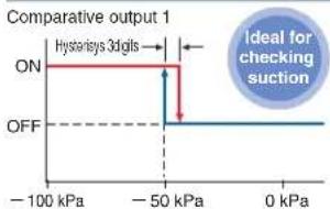
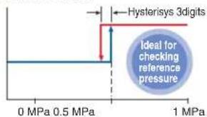
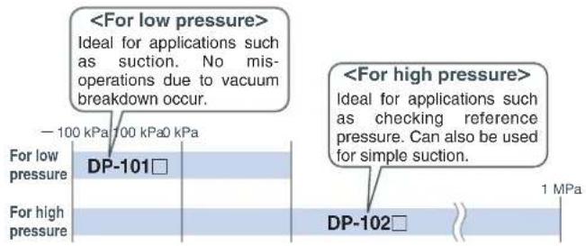
Default settings that can be used straight away
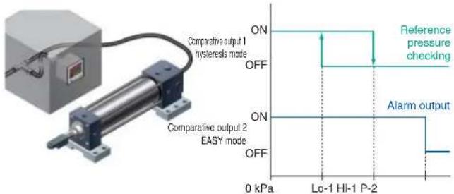
Easy-to-use default settings are provided for applications that are used frequently by pressure sensors. The default settings for low pressure types are ideal for suction checking applications, and those for high pressure types are ideal for checking reference pressure.
Low pressure type High pressure type
line
| Pressure | Output Level | | -------- | ------------ | | -100 kPa | ON | | -50 kPa | ON | | 0 kPa | OFF |Comparative output 1
Buttons with good clicking touch
The buttons have a good clicking touch, allowing smooth setting.
The clicking feeling is transmitted even through gloves.
Reset function
If a problem ever occurs with the sensor settings, they can be returned to the default settings.
Full range of performance and functions in a compact body
All models in the line-up are compound pressure types
No sensor settings are required to switch between positive pressure and negative pressure, so that the number of registered part numbers can be decreased.
Realizes high performance Low pressure type
The low pressure type displays measurements in 0.1 kPa at a resolution of 1/2000 and has a response time of 2.5 ms (variable up to 5,000 ms), ± 0.5 % F.S. temperature characteristics and ± 0.1 % F.S. repeatability, giving it high performance.
Resolution: 1/2,000
Response time: 2.5 ms
Temperature characteristics: ±0.5 % F.S.
Repeatability: ± 0.1 % F.S.
Displays measurements in 0.1 kPa
Equipped with independent dual output Standard type
Equipped with two independent comparative outputs, and separate sensing modes can be selected for each of them. One of the comparative outputs can even be used for alarm output. In addition, if an output is not being used, it can be disabled.
• Vacuum breakdown can also be checked during suction applications!
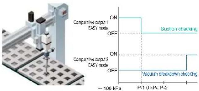
- Reference pressure alarm output is possible during reference pressure checking!
Three output modes are suitable for a wide range of applications
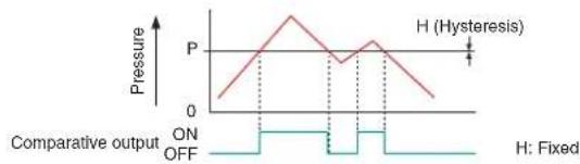
1 EASY mode
This mode is used for comparative output ON / OFF control.
line
| Pressure | Hysteresis | | -------- | ---------- | | 0 | ON | | P | Hysteresis | | OFF | Fixed |Notes: 1) Hysteresis can be fixed to one of eight different levels. 2) 'P-1' appears in the sub display for comparative output 1, and 'P-2' appears for comparative output 2.
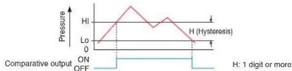
2 Hysteresis mode
This mode is used for setting comparative output hysteresis to the desired level and for carrying out ON / OFF control.
line
| Pressure | Value | | -------- | ----- | | HI | 0 | | Lo | 0 | | ON | ON | | OFF | OFF |Note: 'H, -1' or 'Lo-1' appears in the sub display for comparative output 1, and 'H, -2' or 'Lo-2' appears for comparative output 2.
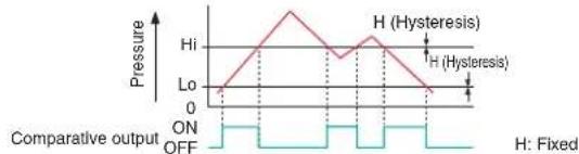
3 Window comparator mode
This mode is used for setting comparative output ON and OFF at pressures within the setting range.
line
| Pressure Level | Value | | -------------- | ----- | | Hi | 0 | | Lo | 0 | | Off | 0 |Notes: 1) Hysteresis can be fixed to one of eight different levels. 2) 'H 1 -1' or 'L0-1' appears in the sub display for comparative output 1, and 'H 1 -2' or 'L0-2' appears for comparative output 2.
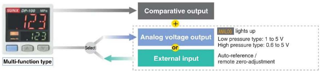
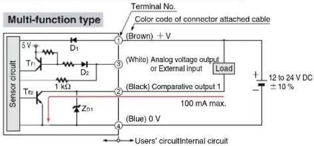
Switching is possible between analog voltage output and external input Multi-function type
Multi-function type is available that allows selection of analog voltage output or external input (auto-reference / remote zero-adjustment). This is suitable for multi-specification applications.
flowchart
graph TD
    A["SUNX DP-100 MPa"] --> B["Multi-function type"]
    B --> C["Select"]
    C --> D["Comparative output"]
    D --> E["Analog voltage output or External input"]
    E --> F["ANALOG lights up\nLow pressure type: 1 to 5 V\nHigh pressure type: 0.6 to 5 V\nAuto-reference / remote zero-adjustment"]
Equipped with auto-reference / remote zero-adjustment functions Multi-function type More precise pressure management is possible with a minimum of effort
If the reference pressure of the device changes, the auto-reference function partially shift the comparative output judgment level by the amount that the reference pressure shifts, and the remote zero-adjustment function can reset the display value to zero via external input. These functions are ideal for places where the reference pressure fluctuates wildly, or where fine settings are desired.
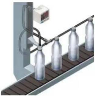
natural_image
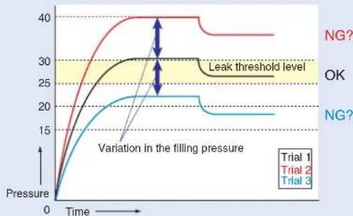
Illustration of a bottle production line with conveyor belt and control unit (no text or symbols)Without auto-reference and remote zero-adjustment functions
Comparative output: Window comparator mode
Hi-1…30, Lo-1…25
Fixed set value
line
| Time | Trial 1 | Trial 2 | Trial 3 | |------|---------|---------|---------| | 0 | 0 | 0 | 0 | | Peak | 40 | 30 | 25 | | Final | 35 | 30 | 20 |Because the threshold level is fixed for conventional pressure sensors, changes in the reference pressure result in wrong decisions.
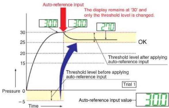
With auto-reference function applied
Comparative output: Window comparator mode
Hi-1…0, Lo-1… - 5
Sets the absolute threshold level
line
| Time | Threshold Level | |------|----------------| | 0 | 0 | | 30 | 30 | | 270 | 270 |When auto-reference input is applied, the reference pressure '30' is added to the threshold level. If the reference pressure changes to '20' or '40', the auto-reference input compensates for this every time by changing the threshold level, so any variation in the filling pressure can be ignored.
With remote zero-adjustment function applied
Comparative output: Window comparator mode
Hi-1…0, Lo-1…—5
Sets the absolute threshold level
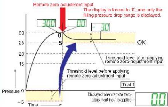
line
| Time | Pressure | |------|----------| | 0 | 30 | | 5 | 25 | | 10 | 20 | | 15 | 15 | | 20 | 10 | | 25 | 5 | | 30 | 0 |When remote zero-adjustment input is applied, the reference pressure is forced to '0'. If the reference pressure changes to '20' or '40', the remote zero-adjustment input adjusts the reference pressure to '0' every time the reference pressure changes, so any variation in the filling pressure can be ignored.
Other useful functions
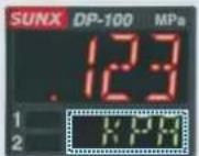
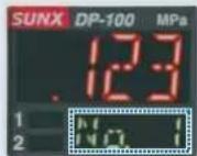
Sub display can be customized
The sub display can be set to indicate any other desired values or letters apart from the threshold value. This eliminates the need for tasks such as affixing a label to the device to indicate the normal pressure value.
Indicates desired values and letters
(Unit display>

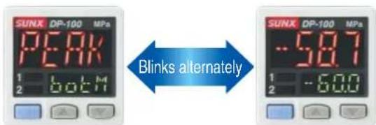
Peak hold and Bottom hold functions
The peak values and bottom values for fluctuating pressures can be displayed using the dual display.
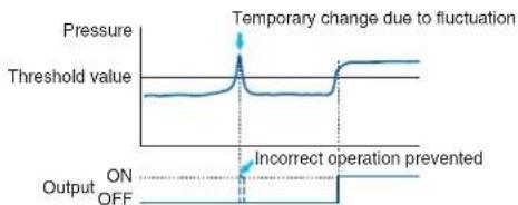
Response time can be changed
The response time can be changed in 10 levels from 2.5 ms to 5,000 ms. This prevents chattering and incorrect operation due to sudden changes in pressure.
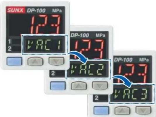
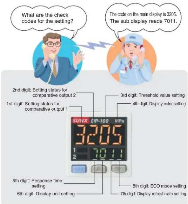
Setting details can be understood at a glance
The DP-100 setting details appear in the digital display. Because the settings are in numeric form that can be easily understood, it is useful for times such as when receiving technical support by telephone.
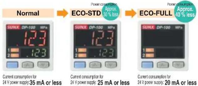
Energy-saving design! Equipped with an ECO mode
This mode lowers the display luminance to cut power consumption by approximately 30 %. The displays can also be turned off completely to achieve a power saving of approximately 40 %.
Display refresh rate can be varied
The display refresh rate for the digital displays can be changed to one of three settings: 250 ms, 500 ms or 1,000 ms. Flickering of the display can be reduced by making the display refresh rate longer.
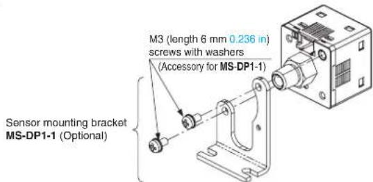
Installation is also easy!
Tight installation to panels is possible
An exclusive mounting bracket that is suitable for 1 to 6 mm 0.039 to 0.236 in panel thickness is available.
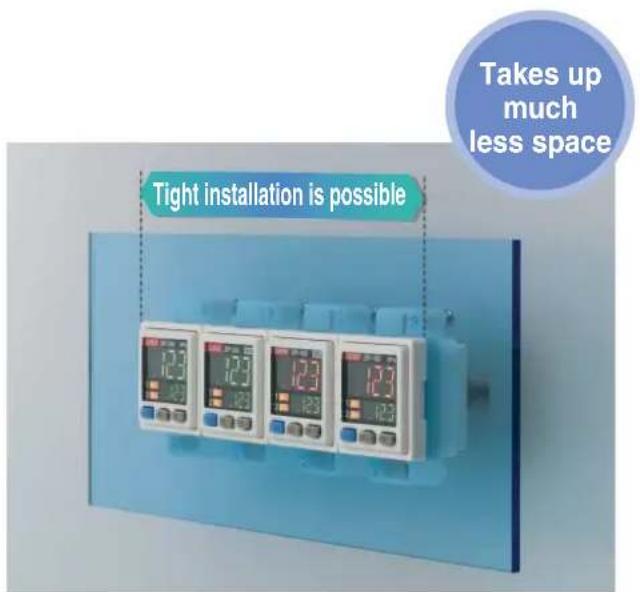
- An exclusive mounting bracket (MS-DP1-1) that supports tight installation is available
Space savings can also be obtained if an L-shaped mounting bracket is used.
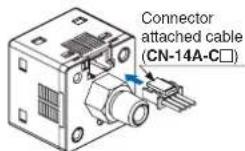
Cable can be connected with one-touch connection
The accessory connector attached cable (2 m 6.562 ft) can be connected easily with one-touch connection.
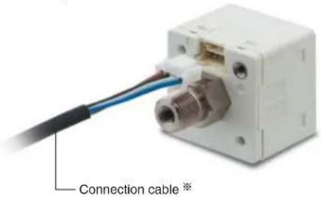
※ Options: 1 m 3.281 ft / 3 m 9.843 ft / 5 m 16.404 ft types are also available.
- Types without connector attached cable are also available
DP-10□-J
Commercially-available connectors can be used for cable connections. Only the required length of cable needs to be used, which contributes to a reduced amount of wastage for unneeded cable.

ORDER GUIDE
| Appearance | Rated pressure range | Model No. Pressure portType | Comparative output | |||
| European North American | Standard | For low pressure | 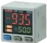 | -100.0 to +100.0 kPa | DP-101 | M5 female thread + R (PT) 1/8 male thread |
| For high pressure | -0.100 to +1.000 MPa | DP-102 | ||||
| Multi-function | For low pressure | -100.0 to +100.0 kPa | DP-101A | |||
| For high pressure | -0.100 to +1.000 MPa | DP-102A | ||||
| European North American | Standard | For low pressure | -100.0 to +100.0 kPa | DP-101-E-P | M5 female thread + G 1/8 male thread | |
| For high pressure | -0.100 to +1.000 MPa | DP-102-E-P | ||||
| Multi-function | For low pressure | -100.0 to +100.0 kPa | DP-101A-E-P | |||
| For high pressure | -0.100 to +1.000 MPa | DP-102A-E-P | ||||
| Standard | For low pressure | -100.0 to +100.0 kPa | DP-101-N | M5 female thread + NPT 1/8 male thread | ||
| DP-101-N-P | ||||||
| For high pressure | -0.100 to +1.000 MPa | DP-102-N | ||||
| DP-102-N-P | ||||||
| Multi-function | For low pressure | -100.0 to +100.0 kPa | DP-101A-N | |||
| DP-101A-N-P | ||||||
| For high pressure | -0.100 to +1.000 MPa | DP-102A-N | ||||
| DP-102A-N-P | ||||||
Types without connector attached cable
Types without connector attached cable are available. When ordering this type, add '-J' at the end of the Model No.
Model No: DP-101-J, DP-101-E-P-J, DP-101-N-J, DP-101-N-P-J
DP-102-J, DP-102-E-P-J, DP-102-N-J, DP-102-N-P-J
Accessory
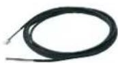
CN-14A-C2 (Connector attached cable 2 m 6.562 ft)
OPTIONS
| Model No. Designation Description | |||
| Connector attached cable | CN-14A-C1 | 1 m 3.281 ft | 0.2 mm ^2 4-core cabtyre cable with connector on one end Cable outer diameter: 3.7 mm 0.146 in |
| CN-14A-C3 | 3 m 9.843 ft | ||
| CN-14A-C5 | 5 m 16.404 ft | ||
| Connector | CN-14AOn the market soon | Set of 10 housings and 40 contacts | |
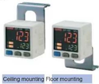
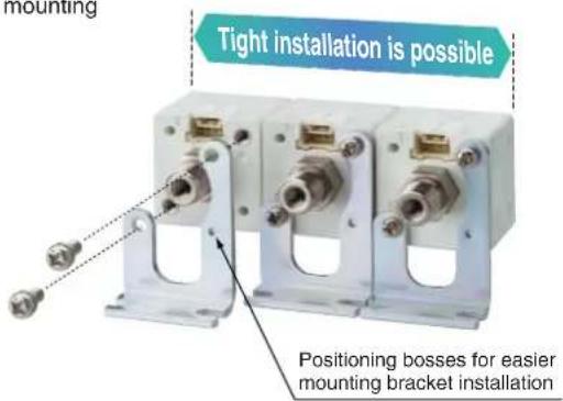
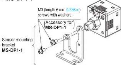
| Sensor mounting bracket | MS-DP1-1 | Allows sensors to be installed to face in the direction of the floor or ceiling. Multiple sensors can also be mounted closely. | |
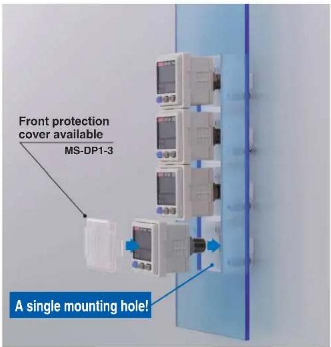
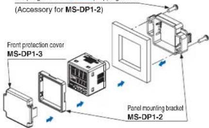
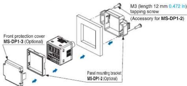
| Panel mounting bracket | MS-DP1-2 | Allows installation to panels with thickness of 1 to 6 mm 0.039 to 0.236 in. | |
| Front protection cover | MS-DP1-3 | Protects the adjustment surfaces of sensors.(Can be attached when using the panel mounting bracket) | |
Sensor mounting bracket
- MS-DP1-1
Panel mounting bracket, Front protection cover
- MS-DP1-2
- MS-DP1-3
M3 (length 12 mm 0.472 in) tapping screw
SPECIFICATIONS
| Type | Standard | Multi-function | |||
| For low pressure For high pressure For low pressure For high pressure | |||||
| Item | Model No. | Asian | DP-102DP-101 DP-102ADP-101A | ||
| European | DP-101-E-P | DP-102-E-P | DP-101A-E-P | ||
| North American (Note 2) | DP-101-N(-P) | DP-102-N(-P) | DP-101A-N(-P) | ||
| Type of pressure | Gauge pressure | ||||
| Rated pressure range | -100.0 to +100.0 kPa | -0.100 to +1.000 MPa | -100.0 to +100.0 kPa | -0.100 to +1.000 MPa | |
| Set pressure range | -100.0 to +100.0 kPa -1.020 to +1.020 kgf/cm^2 \ -1.000 to +1.000 bar \ -14.50 to +14.50 psi \ -750 to +750 mmHg \ -29.5 to 29.5 inHg \ | -0.100 to +1.000 MPa -100 to +1,000 kPa \ -1.02 to +10.20 kgf/cm^2 \ -1.00 to +10.00 bar \ -14.6 to +145.0 psi \ | -100.0 to +100.0 kPa -1.020 to +1.020 kgf/cm^2 \ -1.000 to +1.000 bar \ -14.50 to +14.50 PSI \ -750 to +750 mmHg \ -29.5 to 29.5 inHg \ | -0.100 to +1.000 MPa -100 to +1,000 kPa \ -1.02 to +10.20 kgf/cm^2 \ -1.00 to +10.00 bar \ -14.6 to +145.0 psi \ | |
| Pressure withstandability | 500 kPa 1.5 MPa 500 kPa 1.5 MPa | ||||
| Applicable fluid | Non-corrosive gas | ||||
| Selectable unit | For low pressure: kPa, kgf/cm2, bar, psi, mmHg, inHg, For high pressure: MPa, kPa, kgf/cm2, bar, psi | ||||
| Supply voltage | 12 to 24 V DC ±10% Ripple P-P 10% or less | ||||
| Power consumption | Normal operation: 840 mW or less (Current consumption 35 mA or less at 24 V supply voltage)ECO mode: 600 mW or less at STD (Current consumption 25 mA or less at 24 V supply voltage)480 mW or less at FULL (Current consumption 20 mA or less at 24 V supply voltage) | ||||
| Comparative output | NPN open-collector transistorMaximum sink current: 100 mAApplied voltage: 30 V DC or less (between comparative output and 0 V)Residual voltage: 2 V or less (at 100 mA sink current)PNP open-collector transistorMaximum source current: 100 mAApplied voltage: 30 V DC or less (between comparative output and +V)Residual voltage: 2 V or less (at 100 mA source current) | ||||
| Output operation | NO / NC (selectable by key operation) | ||||
| Output modes | EASY mode / Hysteresis mode / Window comparator mode | ||||
| Hysteresis | Minimum 1 digit (variable) (however, 2 digits when using psi unit) | ||||
| Repeatability | ±0.1% F.S. (within ±2 digits) | ±0.2% F.S. (within ±2 digits) | ±0.1% F.S. (within ±2 digits) | ||
| Response time | 2.5 ms, 5 ms, 10 ms, 25 ms, 50 ms, 100 ms, 250 ms, 500 ms, 1,000 ms, 5,000 ms, selectable by key operation | ||||
| Short-circuit protection | Incorporated | ||||
| External input[Auto-reference function /Remote zero-adjustmentfunction] | —— | ON voltage: 0.4 V DC or lessOFF voltage: 5 to 30 V DC, or openInput impedance: 10 kΩ approx.Input time: 1 ms or more | ON voltage: 5 V to +V DCOFF voltage: 0.6 V DC or less, or openInput impedance: 10 kΩ approx.Input time: 1 ms or more | ||
| Analog voltage output | —— | Output voltage: 1 to 5 V DCZero point: within 3 V ±5% F.SSpan: within 4 V ±5% F.S.Linearity: within ±1% F.S.Output impedance: 1 kΩ approx. | Output voltage: 0.6 to 5 VZero point: within 1 V ±5% F.S Span: within 4.4 V ±5% F.S.Linearity: within ±1% F.S.Output impedance: 1 kΩ approx. | ||
| Display | 4 digits + 4 digits 3-color LCD display (Display refresh rate: 250 ms, 500 ms, 1,000 ms, selectable by key operation) | ||||
| Displayable pressure range | -100.0 to +100.0 kPa -1.020 to +1.020 kgf/cm^2 \ -1.000 to +1.000 bar \ -14.50 to +14.50 psi \ -750 to +750 mmHg \ -29.5 to 29.5 inHg \ | -0.100 to +1.000 MPa -100 to +1,000 kPa -1.02 to +10.20 kgf/cm^2 -1.00 to +10.00 bar -14.6 to +145.0 psi | -100.0 to +100.0 kPa -1.020 to +1.020 kgf/cm^2 -1.000 to +1.000 bar -14.50 to +14.50 psi -750 to +750 mmHg -29.5 to 29.5 inHg | ||
| Indicator | Orange LED Orange LED(Comparative output 1 operation indicator, comparative output 2 operation indicator:Lights up when each comparative output is ON) | (Comparative output 1 operation indicator: Lights up when comparative output is ON),(Analog voltage output operation indicator: Lights up when setting) | |||
| Environmental resistance | Pollution degree | IP40 (IEC) | |||
| Ambient temperature | -10 to +50°C +14 to +122°F, Storage: -10 to +60°C +14 to +140°F | ||||
| Ambient humidity | 35 to 85% RH (No dew condensation or icing allowed), Storage: 35 to 85% RH | ||||
| Voltage withstandability | 1,000 V AC for one min. between all supply terminals connected together and enclosure | ||||
| Insulation resistance | 50 MΩ, or more, with 500 V DC megger between all supply terminals connected together and enclosure | ||||
| Vibration resistance | 10 to 500 Hz frequency, 3 mm 0.118 in amplitude, in X,Y and Z directions for two hours each (when panel is mounted: 10 to 150 Hz frequency, 0.75 mm 0.030 in amplitude, in X,Y and Z directions for two hours each) | ||||
| Shock resistance | 100 m/s2 acceleration (10 G approx.) in X, Y and Z directions for three times each | ||||
| Temperature characteristics | Within ±0.5% F.S. (at +20°C +68°F) Within ±1% F.S. (at +20°C +68°F) | Within ±0.5% F.S. (at +20°C +68°F) | Within ±1% F.S. (at +20°C +68°F) | ||
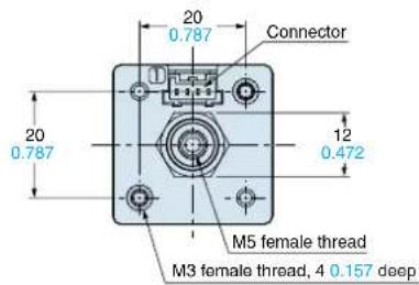
| Pressure port | Asian: M5 female thread + R (PT) 1/8 male thread, European: M5 female thread + G 1/8 male thread, North American: M5 female thread + NPT 1/8 male thread | ||||
| Material | Enclosure: PBT (glass fiber reinforced), LCD display: Acrylic, Pressure port: Brass (nickel plated), Mounting threaded part: Brass (nickel plated), Switch part: Silicone rubber | ||||
| Connecting method | Connector | ||||
| Cable extension | Extension up to total 100 m 328.084 ft (less than 10 m 32.808 ft when conforming to CE marking) is possible with 0.3 mm2, or more, cable | ||||
| Weight | Net weight: 40 g approx., Gross weight: 135 g approx. | ||||
| Accessories | CN-14A-C2 (Connector attached cable 2 m 6.562 ft): 1pc. | ||||
Notes: 1) Where measurement conditions have not been specified precisely, the conditions used were ambient temperature +20 °C +68 °F.
2) Model Nos. of North American standard type having the suffix '-P'
are PNP output type.
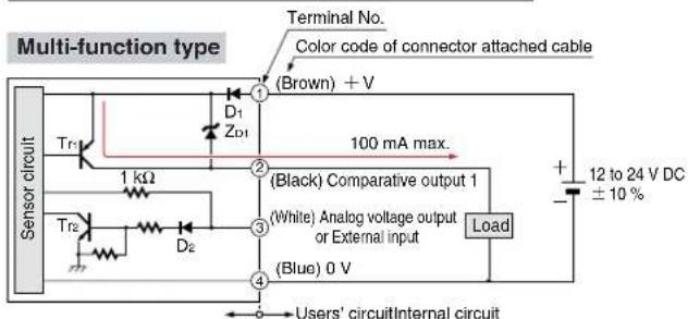
I/O CIRCUIT AND WIRING DIAGRAMS
NPN output type
I/O circuit diagram
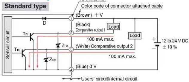
Symbols ... D : Reverse supply polarity protection diode ZD1, ZD2 : Surge absorption zener diode Tr1, Tr2 : NPN output transistor
Symbols ... D1, D2 : Reverse supply polarity protection diode ZD1 : Surge absorption zener diode Tr1 : PNP input transistor Tr2 : NPN output transistor
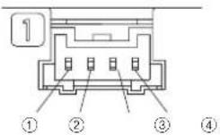
Terminal arrangement diagram
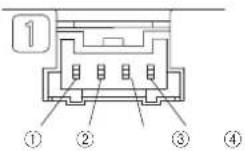
| Terminal | Designation |
| 1 | +V |
| 2 | Comparative output 1 |
| 3 | Standard type: Comparative output 2Multi-function type: Analog voltage output or External input |
| 4 | 0 V |
PNP output type
I/O circuit diagram
![I/O circuit diagram Standard type Terminal No. Color code of connector attached cable (Brown) + V D Sensor circuit Tr1 ZD1 ZD2 (Black) Comparative output 1 100 mA max. 100 mA max. [White] Comparative output 2 (Blue) 0 V Load Load Users' circuitInternal circuit 12 to 24 V DC ± 10 %](/content/2026/05/850937/images/8ad3db90aa5811623c7b1063c0fe51999527b33598f0bb5a1ac4d5b530f8193d.jpg)
Symbols ... D : Reverse supply polarity protection diode ZD1, ZD2 : Surge absorption zener diode Tr1, Tr2 : PNP output transistor
Symbols ... D1, D2: Reverse supply polarity protection diode ZD1: Surge absorption zener diode Tr1: PNP output transistor Tr2: NPN input transistor
Terminal arrangement diagram
| Terminal | Designation |
| 1 | +V |
| 2 | Comparative output 1 |
| 3 | Standard type: Comparative output 2Multi-function type: Analog voltage output or External input |
| 4 | 0 V |
PRECAUTIONS FOR PROPER USE

- Never use this product as a sensing device for personnel protection.
• In case of using sensing devices for personnel protection, use products which meet regulations and standards, such as OSHA, ANSI or IEC etc., for personnel protection applicable in each region or country. - The DP-100 series is designed for use with non-corrosive gas. It cannot be used with liquid or corrosive gas.
Wiring
- Make sure that the power supply is off while wiring.
- Verify that the supply voltage variation is within the rating.
- If power is supplied from a commercial switching regulator, ensure that the frame ground (F.G.) terminal of the power supply is connected to an actual ground.
- In case noise generating equipment (switching regulator, inverter motor, etc.) is used in the vicinity of this sensor, connect the frame ground (F.G.) terminal of the equipment to an actual ground.
- Do not run the wires together with high-voltage lines or power lines or put them in the same raceway. This can cause malfunction due to induction.
- Incorrect wiring will cause problems with operation.
Connection
- Do not apply stress directly to the connection cable leader or to the connector.
Conditions in use for CE conformity
- The DP-100 series is a CE conformity product complying with EMC Directive. The harmonized standard with regard to immunity that applies to this product is EN 61000-6-2 and the following condition must be met to conform to that standard.
Condition
- The sensor should be connected less than 10 m 32.808 ft from the power supply.
Mounting
- The MS-DP1-1 sensor mounting bracket is available separately, and it should be used for mounting. When tightening the sensor to the sensor mounting bracket, use a tightening torque of 0.5 N·m or less.
- The MS-DP1-2 panel mounting bracket (optional) and the MS-DP1-3 front protection cover (optional) are also available.
Piping
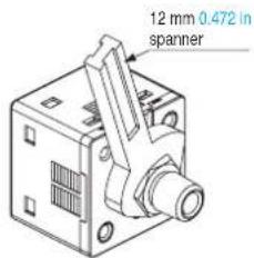
- If connecting a commercially-available coupling to the pressure port, attach a 12 mm 0.472 in spanner (14 mm 0.551 in spanner for DP-100-E type) to the hexagonal section of the pressure port to secure it, and tighten at a torque of 9.8 N·m or less. If it is tightened using excessive torque, it may damage the coupling or the pressure port. In addition, wrap sealing tape around the coupling when connecting it to prevent leaks.
Others
- Use within the rated pressure range.
- Do not apply pressure exceeding the pressure withstandability value. The diaphragm will get damaged and correct operation shall not be maintained.
- Do not use during the initial transient time (0.5 sec. approx.) after the power supply is switched on.
- Avoid dust, dirt, and steam.
• Take care that the sensor does not come in direct contact with water, oil, grease, or organic solvents, such as, thinner, etc. - Do not insert wires, etc., into the pressure port. The diaphragm will get damaged and correct operation shall not be maintained.
- Do not operate the keys with pointed or sharp objects.
RUN mode
• This is the normal operating mode.
| Setting item Description | |
| Threshold value setting | The threshold values for ON / OFF operation can be changed directly by pressing the increment key (UP) and the decrement key (DOWN). |
| Zero-adjustment function | This forces the pressure value display to be reset to zero when the pressure port is open on the atmospheric pressure side. |
| Key lock function | Stops key operations from being accepted. |
| Peak hold / bottom hold function | Displays the peak value and bottom value for fluctuating pressure. The peak value appears in the main display, and the bottom value appears in the sub display. |
MENU SETTING mode
- If the mode selection key is pressed and held for 2 seconds in RUN mode, the mode will switch to MENU SETTING mode.
- If the mode selection key is pressed while a setting is being made, the mode will switch to RUN mode. In this case, the settings that have been changed will be entered.
| Setting item Description | |
| Comparative output 1 output mode setting | Sets the output mode for comparative output 1. |
| Comparative output 2 output mode setting (standard type only) | Sets the output mode for comparative output 2. |
| Analog voltage output / external input switching (multi-function type only) | Allows switching between analog voltage output and auto-reference input / remote zero-adjust-ment input. |
| NO / NC switching | Sets normally open (NO) or normally closed (NC). |
| Response time setting | Sets the response time.The response time can be selected from 2.5 ms, 5 ms, 10 ms, 25 ms, 50 ms, 100 ms, 250 ms, 500 ms, 1,000 ms and 5,000 ms. |
| Display color switching for main display | Allows the color for the main display to be changed.The colors can be set to 'red / green' or 'green / red' to correspond to ON / OFF output, or it can be fixed at 'red' or 'green' all the time. |
| Unit switching | Pressure unit can be changed. |
PRECAUTIONS FOR PROPER USE
PRO mode
- If the mode selection key is pressed and held for 5 seconds in RUN mode, the mode will switch to PRO mode.
- If the mode selection key is pressed while a setting is being made, the mode will switch to RUN mode. In this case, the settings that have been changed will be entered.
| Setting item Description | |
| Sub display switching | Changes the information in the sub display during RUN mode operation to the desired alphanumeric display. |
| Display refresh rate switching | Changes the display refresh rate for the pressure value displayed in the main display. |
| Hysteresis fix value switching | Sets the response time for EASY mode and window comparator mode. (8 steps) |
| Linked display color switching (standard type only) | Allows the display color for the main display to be switched in line with the output operation for comparative output 1 or comparative output 2. |
| ECO mode setting | Allows power consumption to be reduced by dimming the display or turning it off. |
| Setting check code | Allows the setting details to be checked via codes. |
| Setting copy mode | Allows the setting details for the master sensor to be copied to slave sensors. |
| Reset setting | Resets the settings to the factory settings. |
Table of codes
| Code | 1st digit | 2nd digit | 3rd digit | 4th digit | ||||
| Standard type | Multi-function type | |||||||
| Composite output 1 output node | NO / NC switching | Composite output 2 output node | NO / NC switching | Analog voltage output 1 External input | Threshold value display | Display color for main display | Display color linking | |
| 0 | EASY | NO | OFF | OFF | Analog voltage output | P-1, Lo-1 | Red when ON | Comparative output 1 |
| 1 | NC | EASY | NO | Auto-reference | Hi-1 | Comparative output 2 | ||
| 2 | Hysteresis | NO | NC | Remote zero-adjustment | P-2, Lo-2 | Green when ON | Comparative output 1 | |
| 3 | NC | Hysteresis | NO | — | Hi-2 | Comparative output 2 | ||
| 4 | Window comparator | NO | NC | — | ADJ. | Always red | Comparative output 1 | |
| 5 | NC | Window comparator | NO | — | — | Comparative output 2 | ||
| 6 | — | — | NC | Always green | Comparative output 1 | |||
| 7 | — | — | — | — | Comparative output 2 | |||
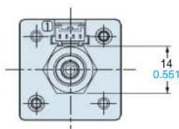
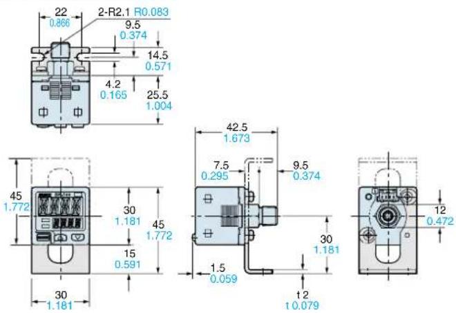
DIMENSIONS (Unit: mm in)
The CAD data in the dimensions can be downloaded from the SUNX website: http://www.sunx.co.jp/
DP-10□ Sensor
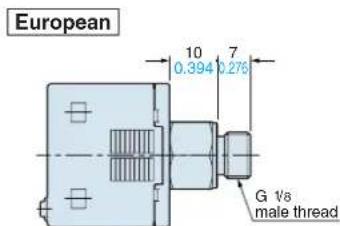
European
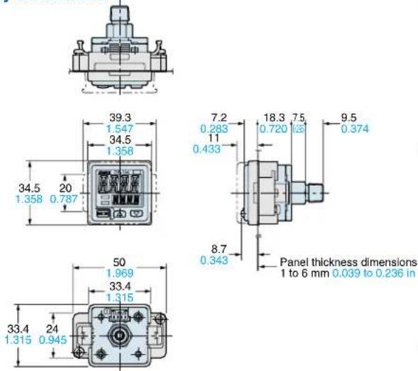
MS-DP1-1
Sensor mounting bracket (Optional)
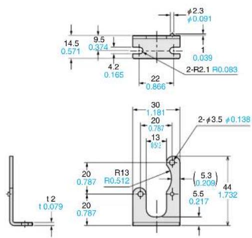
Assembly dimensions
MS-DP1-2
MS-DP1-3
Panel mounting bracket (Optional), Front protection cover (Optional)
Assembly dimensions
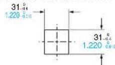
Panel cut-out dimensions
When 1 unit is installed
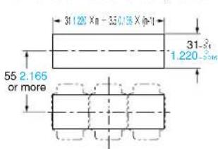
When 'n' units are installed horizontally in series When 'n' units are installed vertically in series
Note: The panel thickness should be 1 to 6 mm 0.039 to 0.236 in.
![31.54 1.220 0.000 31:220 X=+35.0130 X[-1] 55 2.165 or more](/content/2026/05/850937/images/94eb6206086ad7e7d0543b01cc749d52570bd5777b4681663acfadd8f99e22d7.jpg)
Note: The panel thickness should be 1 to 6 mm 0.039 to 0.236 in.
CN-14A-C□
Connector attached cable (Optional, CN-14A-C2 is attached to the sensor)
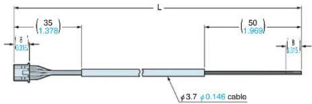
| Model No. Cable length (mm, in) | |
| CN-14A-C1 | 1,000 39.370 |
| CN-14A-C2 | 2,000 78.740 |
| CN-14A-C3 | 3,000 118.110 |
| CN-14A-C5 | 5,000 196.850 |
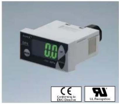
Compact Size • 2-color Digital Display DP4 _SERIES
New shape makes it most suitable for panel installation
Light-weight, compact design
A compact form specifically designed for mounting on an equipment panel. It only uses half the space of our conventional product and provides the lightest weight of just 30 g (cable excluded).
Bright, easy to view two-color digital display
The digital display is a large, easy-to-view, and two-color digital display. It is also functions as an output indicator as it changes from green to red color when the output turns ON, enabling you confirm the output status at a glance.
Supplied with a simple-to-mount panel mounting bracket
A panel mounting bracket (MS-DP-1) is enclosed to enable simple mounting of the sensor onto the panel surface, thus contributing to the total cost reduction.
Rated pressure range: DP4-50/50P 0 to -101.3 kPa DP4-52/52P 0 to 1.000 MPa DP4-57/57P -100.0 to 100.0 kPa
Applicable fluid: Non-corrosive gas
Supply voltage: 12 to 24 V DC + 10 %
Output: DP4-5□ NPN open-collector transistor DP4-5□P PNP open-collector transisto
Pressure port: M5 female thread Dimensions: W40 × H20 × D49 mm
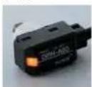
Head-separated Type • 2-color Digital Display DP5 SERIES [Controller SERIES] Sensor head
1/1,000 second high-speed response!
Response time 1 ms
Mounting the detachable head close to the detecting section minimizes piping and enables response time of 1 ms, as well as greatly decreasing tact time delay. In addition, the ultra-small and light-weight design of the head means it can easily be mounted on moving sections.
Sensor head with operation indicator
The sensor head is also equipped with
operation indicator. Output ON / OFF can be checked on the sensor head, so that it is suitable for checking operation at the suction head.
Independent use of sensor head possible
Light-weight, compact design
The controller inherits its lightweight, compact design from the popular DP4 series of digital pressure sensors. Control panel setup is low cost and requires minimal space.
Convenient intermediate cable with connector
Intermediate cable with connectors for connecting the sensor head and the controller makes operation and maintenance easier.
Note: An intermediate cable is required to connect the controller and the sensor head. Please order the intermediate cable with connector separately.
Pressure sensor heads
Rated pressure range: DPH-A□0 0 to -101.3 kPa
DPH-A□2 0 to 1.000 MPa
DPH-A□7 -100.0 to 100.0 kPa
Applicable fluid: Non-corrosive gas
Supply voltage: 12 to 24 V DC _-15^+10 %
Analog voltage output: 1 to 5 V
(over rated pressure range)
Pressure port: DPH-A0□ M5 male thread, DPH-A1□ R (PT) female thread / M5 female thread DPH-A2□ NPT ^1/8 male thread / 10-32UNF female thread DPH-A30 10-32UNF male thread
Dimensions: DPH-A0□/A30 12.5×25×20 mm
DPH-A1□/A2□ 12.5×25×25 mm
Pressure sensor controllers
Applicable pressure sensor head: DPH-A
Rated pressure range: Vacuum pressure 0 to -101.3 kPa
Positive pressure 0 to 1.000 MPa
Compound pressure - 100.0 to 100.0 kPa
Supply voltage: 12 to 24V DC +10% -15%
Comparative Output (Comparative output 1, Comparative output 2):
DP5-C NPN open-collector transistor
DP5-C-P PNP open-collector transistor
Analog voltage output: 1 to 5 V DC (over rated pressure range)
Dimensions: W40×H20×D43 mm
All information is subject to change without prior notice.

Sensing the Future
Overseas Sales Dept.
Phone: +81-(0)568-33-7861