DP-102-M-P - Sensor PANASONIC - Free user manual and instructions
Find the device manual for free DP-102-M-P PANASONIC in PDF.

| Product Type | Digital Pressure Sensor |
| Brand | Panasonic |
| Model | DP-102-M-P |
| Dimensions (W x H x D) | 30 x 28 x 15 mm |
| Weight | Approx. 25 g |
| Power Supply | 12 – 24 V DC ±10% |
| Current Consumption | ≤ 40 mA (without load) |
| Pressure Range | 0 to 1.0 MPa (gauge) |
| Output Type | NPN open collector / PNP open collector (selectable) |
| Display | 3½-digit LED, red |
| Accuracy | ±0.5% F.S. |
| Response Time | ≤ 2.5 ms (ON/OFF) |
| Protection Class | IP40 (IEC) |
| Operating Temperature | 0 to +50 °C |
| Storage Temperature | -10 to +60 °C |
| Main Functions | Auto-zero, peak hold, offset adjustment, output invert |
| Maintenance | Clean exterior with a soft dry cloth; do not use solvents |
| Safety | Use within rated voltage; avoid overpressure; follow manual |
| Spare Parts / Repairability | Contact Panasonic service center; no user-serviceable parts |
| Included Accessories | Instruction manual (20 pages) |
Frequently Asked Questions - DP-102-M-P PANASONIC
User questions about DP-102-M-P PANASONIC
0 question about this device. Answer the ones you know or ask your own.
Ask a new question about this device
Download the instructions for your Sensor in PDF format for free! Find your manual DP-102-M-P - PANASONIC and take your electronic device back in hand. On this page are published all the documents necessary for the use of your device. DP-102-M-P by PANASONIC.
USER MANUAL DP-102-M-P PANASONIC
Conforming to EMC Directive
CRU US
Recognition
S
Certification [DP-101(A)/102(A) only]
Pressure Sensor Evolutions To Come
Achieved further efficiency with 4 upgrades, keeping the same operability
Note: The upgrade will be implemented from production in October 2013, based on stock status.
UPGRADE 1
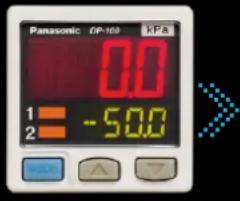
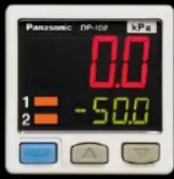
Superior visibility
Improved visibility in Digital Display
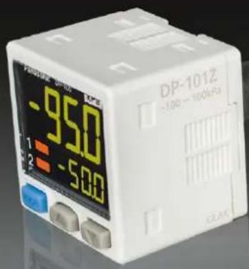
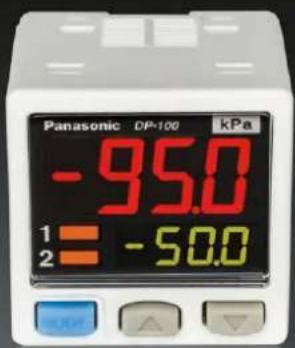
Improvements to the digital display deliver a wide viewing angle along with increased clarity. The display pressure range and set pressure range have also been increased.
Old DP-100 series New DP-100 series
UPGRADE 2
Long-distance transmission of analog output
Addition of analog current output capability to multifunctional models
Users can now select either voltage output or current output as analog output according to their application.
UPGRADE 3
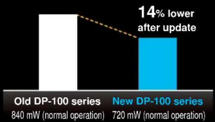
Reduced environmental impact
14% lower power consumption (during normal operation)
Thanks to a redesign of its circuitry, power consumption of the low-power-consumption DP-100 series during normal operation has been reduced by 14%. The display is shut off entirely during ECO / FULL mode operation for power savings of up to 50% compared to normal operation, and display brightness is lowered during ECO / STD mode operation for power savings of up to 30% compared to normal operation.
bar
| Series | Power (mW) | Normal Operation | | :--- | :--- | :--- | | Old DP-100 series | 840 | | | New DP-100 series | 720 | 14% lower after update |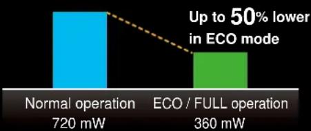
bar
| Operation Type | Power (mW) | | ---------------------- | ---------- | | Normal operation | 720 | | ECO / FULL operation | 360 |UPGRADE 4
Enhanced power circuitry
Addition of a reverse polarity protection circuit to the transistor output circuit
To prevent from breakage due to miswiring.
A new global standard
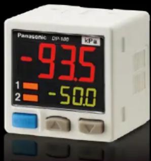
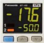
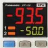
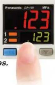
Dual Display
Direct setting
"Current value" and "threshold value" can be checked at the same time!
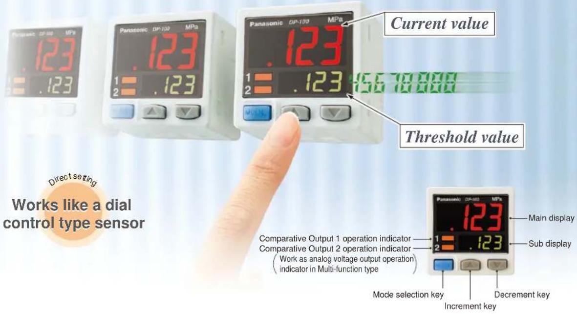
Dual display allows direct setting of threshold value
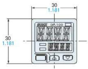
Equipped with a 30 mm 1.181 in square compact-sized dual display. The current value and the threshold value can be checked at the same time, so the threshold value can be set and checked smoothly without switching to another screen mode. ON / OFF operations still continue while the threshold values are being set, so setting to the same sensitivity as dial control-type sensors is possible. Key lock function is equipped as well.
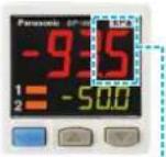
3-color display (Red, Green, Orange)
The main display changes color in line with changes in the status of output ON / OFF operation, and it also changes color while setting is in progress. The sensor status can therefore be understood easily, and operating errors can be reduced.
Readable digital display!
Alphanumeric indication in 12 segments is used. This improved visual checking.
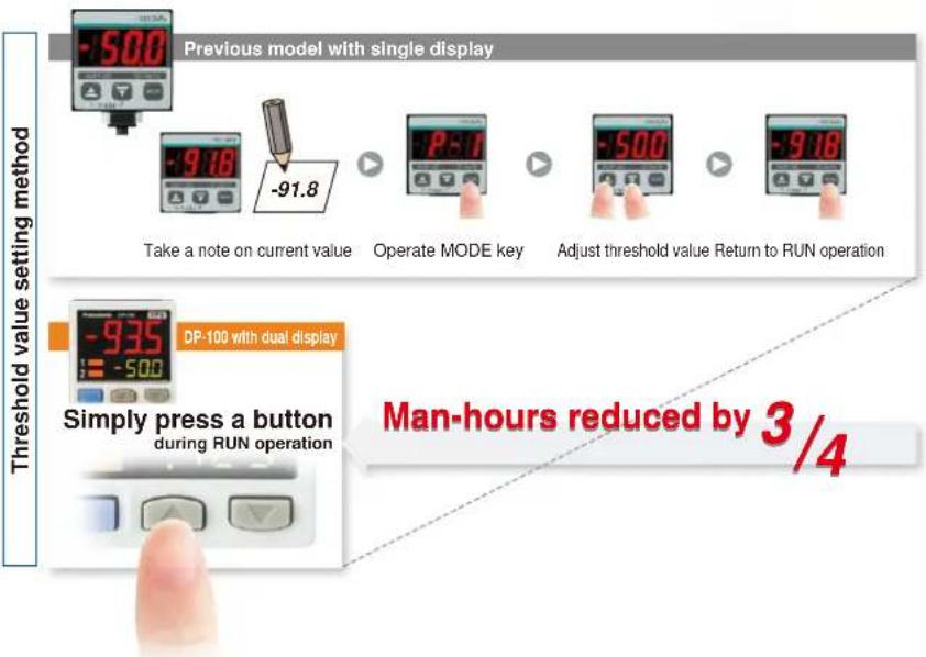
During normal operation During setting
Copy function helps operation to be accurate and quick
Copy function reduces man-hours and human error
Sensors can be connected to a master sensor one by one, and a copy of the setting details for the master sensor can be transmitted as data to other sensors. If making the same settings for multiple sensors, this prevents setting errors among other sensors and in addition, when machinery design are changed, there would be less change in work orders.
Setting details can be copied.
Copying via wiring
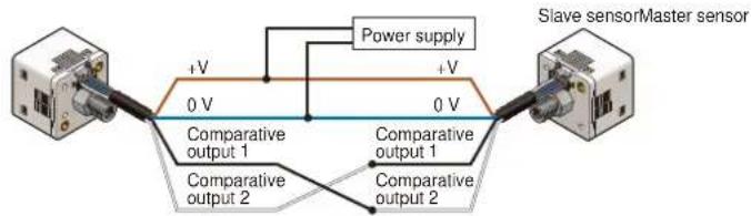
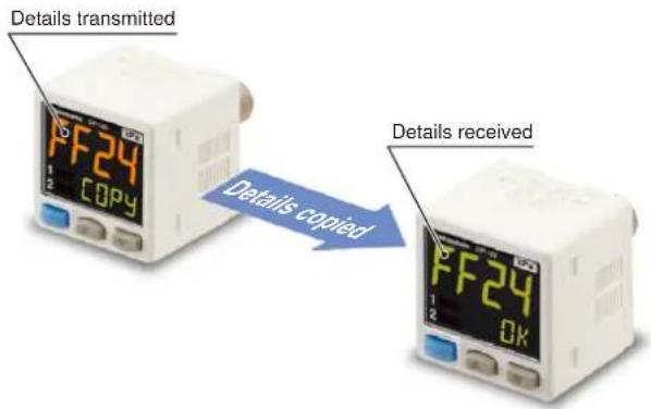
Note: Settings cannot be copied from the new version (Ver. 2) to the old version. However, settings can be copied from the old version to the new version (Ver. 2).
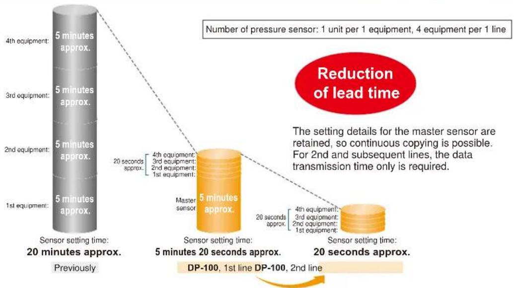
Advantage
1 Setting man-hours are reduced and sensor setting time is shortened.
flowchart
graph TD
    A["1st equipment: 5 minutes approx."] --> B["2nd equipment: 5 minutes approx."]
    B --> C["3rd equipment: 5 minutes approx."]
    C --> D["4th equipment: 5 minutes approx."]
    D --> E["Previous Sensor setting time: 20 minutes approx."]
    E --> F["Sensor setting time: 5 minutes 20 seconds approx."]
    F --> G["DP-100, 1st line: 5 minutes approx."]
    F --> H["DP-100, 2nd line: 20 seconds approx."]
    G --> I["Sensor setting time: 20 seconds approx."]
    H --> J["Sensor setting time: 2nd line: 4 seconds approx."]
    I --> K["Number of pressure sensor: 1 unit per 1 equipment, 4 equipment per 1 line"]
    J --> L["Reduction of lead time"]
    style A fill:#f9f,stroke:#333
    style B fill:#f9f,stroke:#333
    style C fill:#f9f,stroke:#333
    style D fill:#f9f,stroke:#333
    style E fill:#ccf,stroke:#333
    style F fill:#ccf,stroke:#333
    style G fill:#ccf,stroke:#333
    style H fill:#ccf,stroke:#333
    style I fill:#dfd,stroke:#333
    style J fill:#dfd,stroke:#333
    style K fill:#dfd,stroke:#333
Advantage
2 Human operating error is reduced.
- Because all details are copied automatically, problems as a result of human error can be prevented.
- Instruction manuals can be updated easily when changes are made to equipment design.
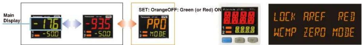
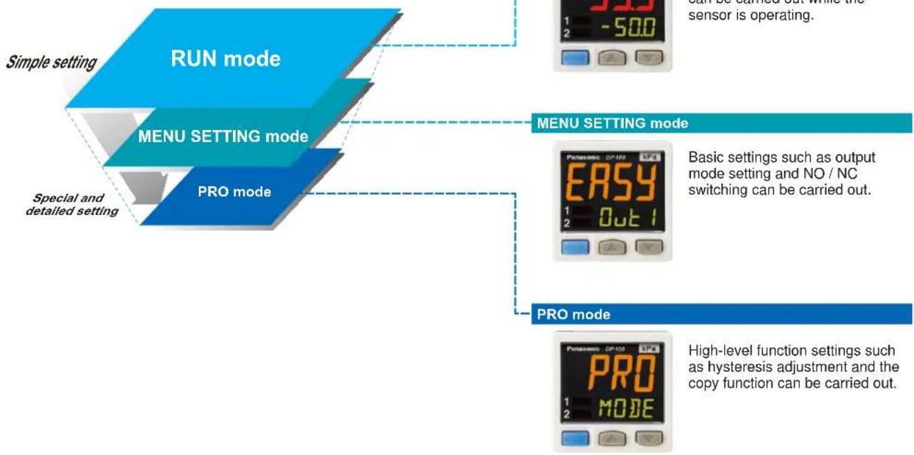
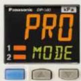
Setting is smooth and easy
The sensor's setting operation mode has a 3-level configuration to suit the frequency of use.
The setting levels are clearly separated into "RUN mode" for operation settings that are carried out daily, "MENU SETTING mode" for basic settings, and "PRO mode" for special and detailed setting. These make setting operations easy to understand and easy to carry out.
flowchart
graph TD
    A["Simple setting"] --> B["RUN mode"]
    C["MENU SETTING mode"] --> B
    D["PRO mode"] --> B
    B --> E["CAN is turned out while the sensor is operating."]
    B --> F["MENU SETTING mode"]
    F --> G["Basic settings such as output mode setting and NO / NC switching can be carried out."]
    F --> H["PRO mode"]
    H --> I["High-level function settings such as hysteresis adjustment and the copy function can be carried out."]
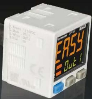
Displayed in orange while setting is in progress
The display appears in red and green during RUN operation, but it changes to orange while setting is in progress, so that the sensor status can be viewed at a glance.
RUN operation While setting
or
RUN mode
MENU SETTING mode
PRO mode
Red or green when output is ON / OFF Orange while setting is in progress
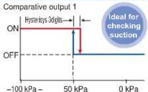
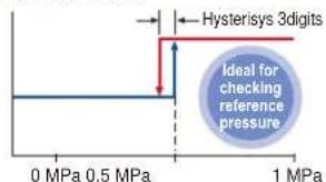
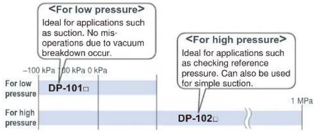
Default settings that can be used straight away
Easy-to-use default settings are provided for applications that are used frequently by pressure sensors. The default settings for low pressure types are ideal for suction confirmation applications, and those for high pressure types are ideal for checking reference pressure.
Low pressure type High pressure type
line
| Pressure | Output Level | | -------- | ------------ | | -100 kPa | ON | | 50 kPa | ON | | 0 kPa | OFF |Comparative output 1
Buttons with good clicking touch
The buttons have a good clicking touch, allowing smooth setting.
The clicking feeling is transmitted even through gloves.
Reset function
If a problem ever occurs with the sensor settings, they can be reset to the default settings.
Full range of performance and functions in a compact body
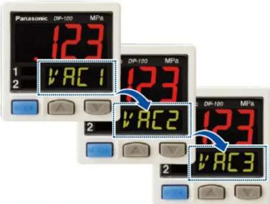
All lineup models are compound pressure types
No sensor settings are required to switch between positive pressure and negative pressure, so that the number of registered part numbers can be decreased.
High performance accomplished Low pressure type
The low pressure type displays measurements in 0.1 kPa at a resolution of 1/2,000 and has a response time of 2.5 ms (variable up to 5,000 ms), ±0.5 % F.S. temperature characteristics and ±0.1 % F.S. repeatability, achieving high detection performance.
Resolution: 1/2,000
Response time: 2.5 ms
Temperature characteristics: ±0.5 % F.S.
Repeatability: ±0.1 % F.S.
Displays measurements in 0.1 kPa
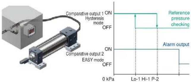
Equipped with independent dual output Standard type
Equipped with two independent comparative outputs, and separate sensing modes can be selected for each of them. Since there are two comparative outputs, one of the comparative outputs can even be used for alarm output. In addition, output, which is not being used, can be disabled.
• Vacuum breakdown can also be notified during suction applications!
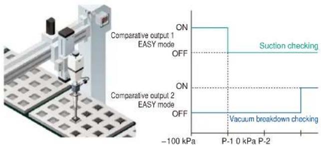
• Reference pressure alarm output is possible during reference pressure checking!
Three output modes are suitable for a wide range of applications
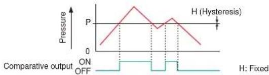
1 EASY mode
This mode is used for comparative output ON / OFF control.
line
| Pressure | Value | | -------- | ----- | | P | 0 | | H (Hysteresis) | 1 | | H (Hysteresis) | 0 | | H (Hysteresis) | -1 | | H (Hysteresis) | -2 | | H (Hysteresis) | -3 | | H (Hysteresis) | -4 | | H (Hysteresis) | -5 | | H (Hysteresis) | -6 | | H (Hysteresis) | -7 | | H (Hysteresis) | -8 | | H (Hysteresis) | -9 | | H (Hysteresis) | -10 | | H (Hysteresis) | -11 | | H (Hysteresis) | -12 | | H (Hysteresis) | -13 | | H (Hysteresis) | -14 | | H (Hysteresis) | -15 | | H (Hysteresis) | -16 | | H (Hysteresis) | -17 | | H (Hysteresis) | -18 | | H (Hysteresis) | -19 | | H (Hysteresis) | -20 | | H (Hysteresis) | -21 | | H (Hysteresis) | -22 | | H (Hysteresis) | -23 | | H (Hysteresis) | -24 | | H (Hysteresis) | -25 | | H (Hysteresis) | -26 | | H (Hysteresis) | -27 | | H (Hysteresis) | -28 | | H (Hysteresis) | -29 | | H (Hysteresis) | -30 | | H (Hysteresis) | -31 | | H (Hysteresis) | -32 | | H (Hysteresis) | -33 | | H (Hysteresis) | -34 | | H (Hysteresis) | -35 | | H (Hysteresis) | -36 | | H (Hysteresis) | -37 | | H (Hysteresis) | -38 | | H (Hysteresis) | -39 | | H (Hysteresis) | -40 | | H (Hysteresis) | -41 | | H (Hysteresis) | -42 | | H (Hysteresis) | -43 | | H (Hysteresis) | -44 | | H (Hysteresis) | -45 | | H (Hysteresis) | -46 | | H (Hysteresis) | -47 | | H (Hysteresis) | -48 | | H (Hysteresis) | -49 | | H (Hysteresis) | -50 | | H (Hysteresis) | -51 | | H (Hysteresis) | -52 | | H (Hysteresis) | -53 | | H (Hysteresis) | -54 | | H (Hysteresis) | -55 | | H (Hysteresis) | -56 | | H (Hysteresis) | -57 | | H (Hysteresis) | -58 | | H (Hysteresis) | -59 | | H (Hysteresis) | -60 | | H (Hysteresis) | -61 | | H (Hysteresis) | -62 | | H (Hysteresis) | -63 | | H (Hysteresis) | -64 | | H (Hysteresis) | -65 | | H (Hysteresis) | -66 | | H (Hysteresis) | -67 | | H (Hysteresis) | -68 | | H (Hysteresis) | -69 | | H (Hysteresis) | -70 | | H (Hysteresis) | -71 | | H (Hysteresis) | -72 | | H (Hysteresis) | -73 | | H (Hysteresis) | -74 | | H (Hysteresis) | -75 | | H (Hysteresis) | -76 | | H (Hysteresis) | -77 | | H (Hysteresis) | -78 | | H (Hysteresis) | -79 | | H (Hysteresis) | -80 | | H (Hysteresis) | -81 | | H (Hysteresis) | -82 | | H (Hysteresis) | -83 | | H (Hysteresis) | -84 | | H (Hysteresis) | -85 | | H (Hysteresis) | -86 | | H (Hysteresis) | -87 | | H (Hysteresis) | -88 | | H (Hysteresis) | -89 | | H (Hysteresis) | -90 | | H (Hysteresis) | -91 | | H (Hysteresis) | -92 | | H (Hysteresis) | -93 | | H (Hysteresis) | -94 | | H (Hysteresis) | -95 | | H (Hysteresis) | -96 | | H (Hysteresis) | -97 | | H (Hysteresis) | -98 | | H (Hysteresis) | -99 | | H (Hysteresis) | -100 |Notes: 1) Hysteresis can be fixed to one of eight different levels. 2) "P-1" appears in the sub display for comparative output 1, and "P-2" appears for comparative output 2.
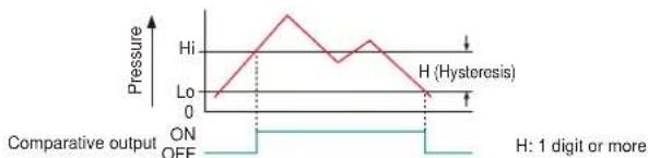
2 Hysteresis mode
This mode is used for setting comparative output hysteresis to the desired level and for carrying out ON / OFF control.
line
| Pressure | Value | | -------- | ----- | | Hi | 0 | | Lo | 0 | | Off | 0 |Note: " H_1-1 " or "Lo-1" appears in the sub display for comparative output 1, and " H_1-2 " or "Lo-2" appears for comparative output 2.
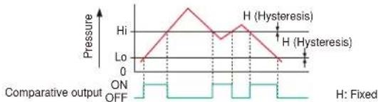
3 Window comparator mode
This mode is used for setting comparative output ON and OFF at pressures within the setting range.
line
| Pressure | Value | | -------- | ----- | | Hi | 0 | | Lo | 0 | | Off | 0 |Notes: 1) Hysteresis can be fixed to one of eight different levels. 2) “ H_i-I ” or “ L_0-I ” appears in the sub display for comparative output 1, and “ H_i-2 ” or “ L_0-2 ” appears for comparative output 2.
Equipped with auto-reference / remote zero-adjustment functions, More precise pressure management is achieved with a minimum of effort
Multi-function type
If the reference pressure of the device changes, two functions are selectable. One is auto-reference function, which partially shift the comparative output judgment level by the amount that the reference pressure shifts. The other is remote zero-adjustment function, which can reset the display value to zero via external input. These functions are ideal for places where the reference pressure fluctuates wildly, or where fine settings are required.
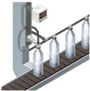
natural_image
Illustration of a bottle production line with four bottles on a conveyor belt, no text or symbols present.Without auto-reference and remote zero-adjustment functions
Comparative output: Window comparator mode
Hi-1…30, Lo-1…25
Fixed set value
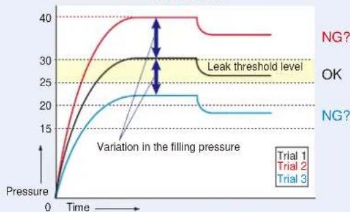
line
| Time | Trial 1 | Trial 2 | Trial 3 | |------|---------|---------|---------| | 0 | 0 | 0 | 0 | | Peak | 40 | 30 | 25 | | Final | 35 | 30 | 20 |Because the threshold level is fixed for conventional pressure sensors, changes in the reference pressure result in wrong decisions.
With auto-reference function applied
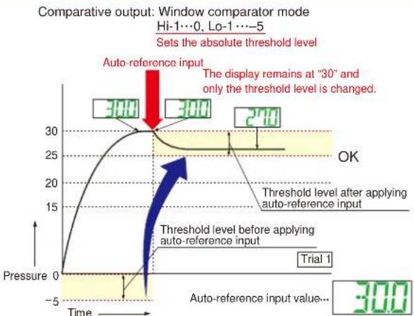
line
| Time | Pressure | |------|----------| | 0 | 0 | | 15 | 15 | | 30 | 30 | | 300 | 300 | | 300 | 240 |When auto-reference input is applied, the reference pressure "30" is added to the threshold level. If the reference pressure changes to "20" or "40", the auto-reference input compensates for this every time by changing the threshold level, so any variation in the filling pressure can be ignored.
With remote zero-adjustment function applied
Comparative output: Window comparator mode
Hi-1…0, Lo-1…-5
Sets the absolute threshold level
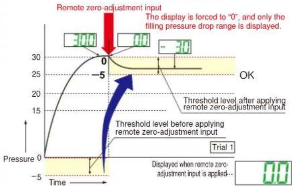
line
| Time | Pressure | |------|----------| | 0 | 300 | | -5 | 0 | | 30 | 30 |When remote zero-adjustment input is applied, the reference pressure is forced to "0". If the reference pressure changes to "20" or "40", the remote zero-adjustment input adjusts the reference pressure to "0" every time the reference pressure changes, so any variation in the filling pressure can be ignored.
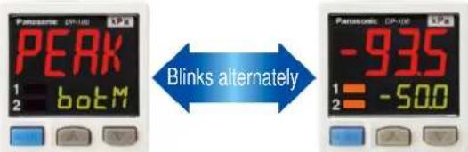
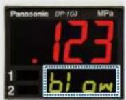
Peak hold and Bottom hold functions
The peak values and bottom values for fluctuating pressures can be displayed using the dual display.
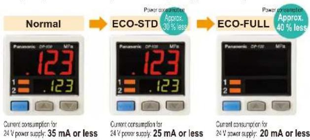
Energy-saving design! Equipped with an ECO mode
This mode lowers the display luminance to cut power consumption by approximately 30 %. The displays can also be turned off completely to achieve a power saving of approximately 40 %.
Other useful functions
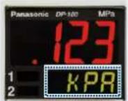
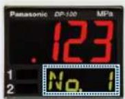
Sub display can be customized
The sub display can be set to indicate any other desired values or letters apart from the threshold value. This eliminates the need for tasks such as affixing a label to the device to indicate the normal pressure value.
Indicates desired values and letters
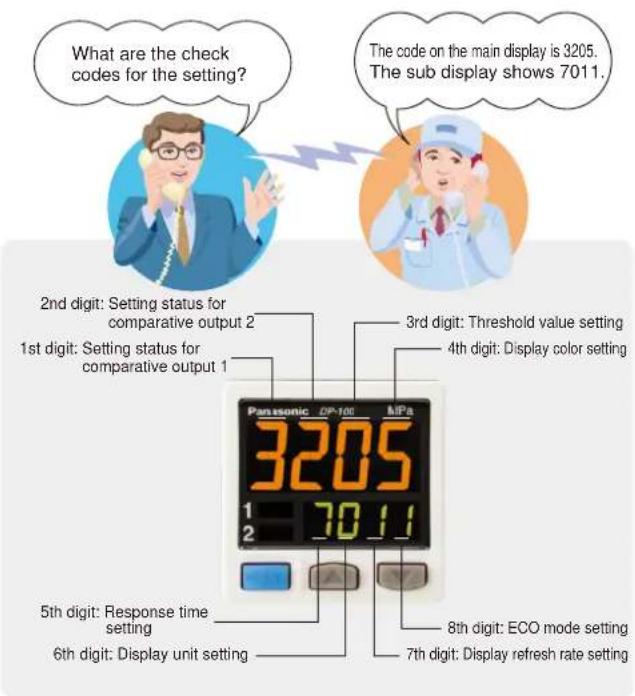
Setting details can be recognized at a glance
The DP-100 setting details appear in the digital display. Because the settings are in numeric form that can be easily understood, it is useful such as when receiving technical support by telephone.
Cable can be connected with one-touch
Connector attached cable (2m 6.562 ft), as an accessory, can be connected easily with one-touch connection.
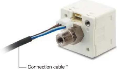
* Options: 1 m 3.281 ft / 3 m 9.843 ft / 5 m 16.404 ft types are also available.
- Types without connector attached cable are also available
Commercially-available connectors can be used for cable connections. Cables in required length can be used, so this contributes to reduction in waste of unwanted cables.

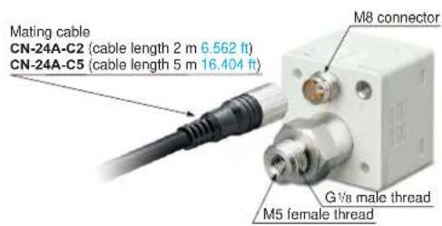
• M8 plug-in connector types are also available (Only for Europe)
DP-11□-E-P-J
Installation is also easy!
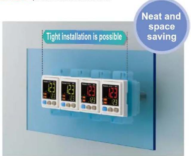
Tight installation to panels is possible
An exclusive mounting bracket that is suitable for 1 to 6 mm 0.039 to 0.236 in panel thickness is available.
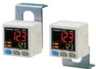
- An exclusive mounting bracket that supports tight installation is available
Space savings can also be achieved even when an L-shaped mounting bracket is used.
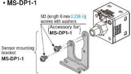
- MS-DP1-1
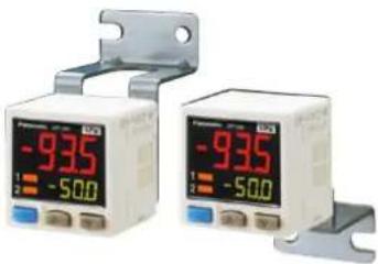
natural_image
Two identical medical pressure meter devices with digital displays and adjustable arm brackets (no visible text or labels)Ceiling mounting Floor mounting Rear mounting
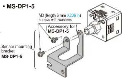
- MS-DP1-5
Tight installation is possible
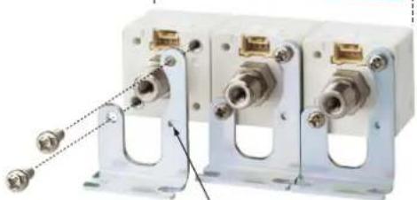
natural_image
Three white industrial electrical connectors with metal fittings and connectors, no visible text or symbolsPositioning bosses for easier mounting bracket installation
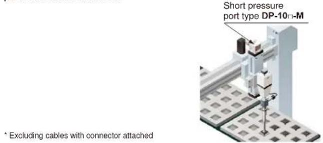
Short pressure port type is lightweight and takes up little space
Space saving!
Compact size with a depth of only 30 mm 1.181 in, so that it can easily fit into narrow spaces.
![Standard type M5 female thread+R½ male thread Elbow joint Short pressure port type 30 mm 1.181 in Shortened to 12.5 mm 0.492 in ! Light weight 30g approx. M5 female thread [Material: Stainless steel (SUS)]](/content/2026/05/1010944/images/b8677c8f8b92cdecd3e167ddb84cb94382e2226d747d1d345de4629d8e6c3f3e.jpg)
* The illustration shows connection using an elbow joint. The elbow joint is sold separately.
Light weight of 30 g! \*
10 g lighter than standard types. This reduces the loads on movable parts such as robot arms.
Ideal for clean environments!
Stainless steel (SUS303) which does not rust or generate gas is used as the port material.
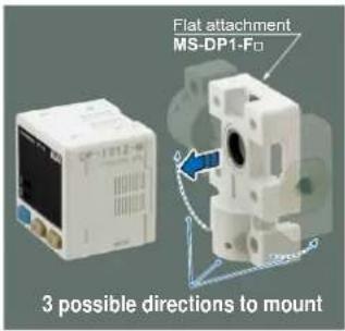
Flat installation on the wall by shifting the direction of the pressure port For short pressure port type
By mounting the flat attachment to DP-10□-M(-P), pressure port and cable can now be pulled out in downward, left or right directions. Flat mounting on surfaces such as the wall is made possible.
For short pressure port type
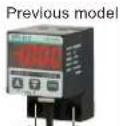
Previous model DP2 / DP3 series can be switched over to DP-100 series.
20 mm
0.787 in pitch
20 mm
0.787 in pitch
| Model No. | Pressure port |
| MS-DP1-FM | M5 female thread |
| MS-DP1-FR | Rc^1/8 female thread |
| MS-DP1-FN | NPT^1/8 female thread |
| MS-DP1-FE | G^1/8 female thread |
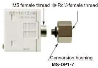
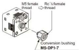
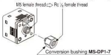
Rc^1/8 conversion bushing is available. Compatible with previous model
By equipping the push-in converter with DP-10-M(-P), pressure port can be converted from M5 female thread to Rc1/8 female thread. Bore diameter conversion to the DP2 / DP3 series is possible.
ORDER GUIDE
| Appearance | Rated pressure range | Model No. Pressure | portType | Comparative output | ||||
| Standard pressure port type Short pressure port type | Asia | Standard | For low pressure | 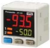 *CN-14A-C2(Connector attached)cable 2 m 6.562 ft is attached.(Excluding M8 plug-in)connector type *CN-14A-C2(Connector attached)cable 2 m 6.562 ft is attached.(Excluding M8 plug-in)connector type | -100.0 to +100.0 kPa | DP-101 | M5 female thread+R ^1/8 male thread | NPN open-collector transistor |
| For high pressure | -0.100 to +1.000 MPa | DP-102 | ||||||
| Multi-function | For low pressure | -100.0 to +100.0 kPa | DP-101A | |||||
| For high pressure | -0.100 to +1.000 MPa | DP-102A | ||||||
| Europe | Standard | For low pressure | -100.0 to +100.0 kPa | DP-101-E-P | M5 female thread+G ^1/8 male thread | PNP open-collector transistor | ||
| For high pressure | -0.100 to +1.000 MPa | DP-102-E-P | ||||||
| Multi-function | For low pressure | -100.0 to +100.0 kPa | DP-101A-E-P | |||||
| For high pressure | -0.100 to +1.000 MPa | DP-102A-E-P | ||||||
| North America | Standard | For low pressure | -100.0 to +100.0 kPa | DP-111-E-P-J | M5 female thread+G ^1/8 male thread | PNP open-collector transistor | ||
| For high pressure | -0.100 to +1.000 MPa | DP-112-E-P-J | ||||||
| Multi-function | For low pressure | -100.0 to +100.0 kPa | DP-111A-E-P-J | |||||
| For high pressure | -0.100 to +1.000 MPa | DP-112A-E-P-J | ||||||
| NPN open-collector transistor | ||||||||
| PNP open-collector transistor | ||||||||
| NPN open-collector transistor | ||||||||
| PNP open-collector transistor | ||||||||
| NPN open-collector transistor | ||||||||
| PNP open-collector transistor | ||||||||
| NPN open-collector transistor | ||||||||
| PNP open-collector transistor | ||||||||
| NPN open-collector transistor | ||||||||
| PNP open-collector transistor | ||||||||
| NPN open-collector transistor | ||||||||
| PNP open-collector transistor | ||||||||
| NPN open-collector transistor | ||||||||
| PNP Open-collector transistor | ||||||||
Type without connector attached cable
Type without connector attached cable CN-14A-C2 is available. When ordering this type, suffix "-J" to the end of Model No. (e.g.) Type without connector attached cable of DP-101-N is "DP-101-N-J"
Accessory
• CN-14A-C2
(Connector attached cable 2 m 6.562 ft)
OPTIONS
| Model No. Designation Description | |||
| Connector attached cable | CN-14A-C1 | Length: 1 m 3.281 ft | 0.2 mm ^2 4-core cabtyre cable with connector on one endCable outer diameter: .7 mm 0.146 in |
| CN-14A-C2 (Note) | Length: 2 m 6.562 ft | ||
| CN-14A-C3 | Length: 3 m 9.843 ft | ||
| CN-14A-C5 | Length: 5 m 16.404 ft | ||
| Connector attached cable (Flexible cable) | CN-14A-R-C1 | Length: 1 m 3.281 ft | 0.2 mm ^2 4-core flexible cabtyre cable with connector on one endCable outer diameter: .7 mm 0.146 in |
| CN-14A-R-C2 | Length: 2 m 6.562 ft | ||
| CN-14A-R-C3 | Length: 3 m 9.843 ft | ||
| CN-14A-R-C5 | Length: 5 m 16.404 ft | ||
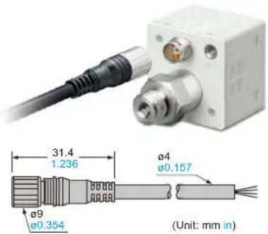
| M8 connector attached cable | CN-24A-C2 | Length: 2 m 6.562 ft | For M8 plug-in connector typeThe connector on one endCable outer diameter: 4 mm 0.157 in |
| CN-24A-C5 | Length: 5 m 16.404 ft | ||
| Connector | CN-14A | Set of 10 housings and 40 contacts | |
| Sensor mounting bracket | MS-DP1-1 | Allows sensors to be installed on the flooring or ceiling.Multiple sensors can also be mounted closely. | |
| MS-DP1-5 | Allows sensors to be installed on the wall. Multiple sensors can also be mounted closely. | ||
| Panel mounting bracket | MS-DP1-2 | Allows installation to panels with thickness of 1 to 6 mm 0.039 to 0.236 in. Multiple sensors can also be mounted closely. | |
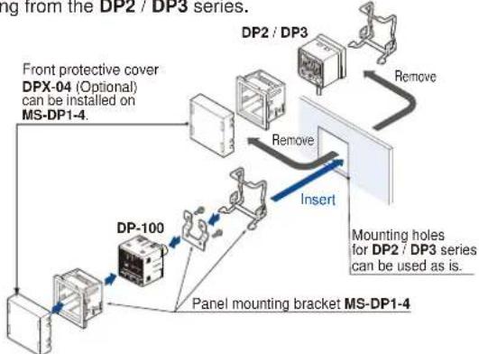
| MS-DP1-4 | Allows replacement from DP2 / DP3 series to DP-100 series. For newly designed set-up, please use panel mounting bracket MS-DP1-2 for panel mounting. | ||
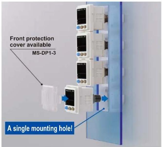
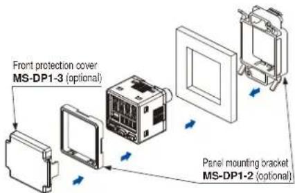
| Front protection cover | MS-DP1-3 | Protects the adjustment surfaces of sensors.(Can be attached when using the panel mounting bracket) | |
| Conversion bushing | MS-DP1-7 | By equipping with DP-10= -M(-P), pressure port can be converted to Rc ^1/_8 female thread. Replacement from DP2 / DP3 series is possible. | |
| Flat attachment | MS-DP1-FM | M5 female thread | Pressure port and cable can now be pulled out in downward, left or right directions. Flat mounting on surfaces such as the wall is made possible. |
| MS-DP1-FR | Rc ^1/_8 female thread | ||
| MS-DP1-FN | NPT ^1/_8 female thread | ||
| MS-DP1-FE | G ^1/_8 female thread | ||
Connector attached cable
• CN-14A-C□
• CN-14A-R-C□
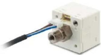
natural_image
Close-up of a white electronic device with a blue cable inserted into the connector (no visible text or symbols)M8 connector attached cable
• CN-24A-C□
Note: The connector attached cable CN-14A-C2 is supplied with the DP-100 series.
(Excluding M8 plug-in connector type).
Panel mounting bracket, Front protection cover
- MS-DP1-2
- MS-DP1-3
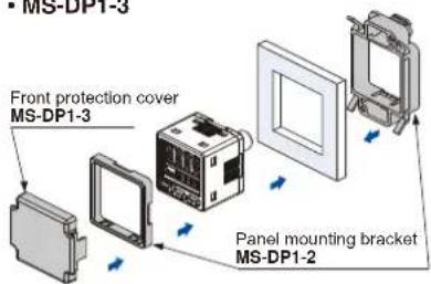
- MS-DP1-4
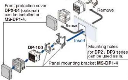
flowchart
graph TD
    A["Front protection cover DPX-04 (optional) can be installed on MS-DP1-4."] --> B["Remove"]
    B --> C["Mounting holes for DP2 / DP3 series can be used as is."]
    C --> D["Panel mounting bracket MS-DP1-4"]
    D --> E["DP-100"]
    E --> F["Remove"]
    F --> G["Insert"]
    G --> H["Front protection cover DPX-04 (optional) can be installed on MS-DP1-4."]
Sensor mounting bracket
- MS-DP1-1
Flat attachment
• MS-DP1-FM • MS-DP1-FR

Net weight: MS-DP1-FM 15g approx.
MS-DP1-FR/FN/FE 25g approx.
Two M3 (length 8 mm 0.315 in) screws,
two M4 (length 20 mm 0.787 in) screws are attached.
Recommended connector
Contact: SPHD-001T-P0.5, Housing: PAP-04V-S
(Manufactured by J.S.T. Mfg. Co., Ltd.)
Note: Contact the manufacturer for details of the recommended products.
Recommended crimping tool
Model No.: YC-610R
(Manufactured by J.S.T. Mfg. Co., Ltd.)
Note: Contact the manufacturer for details of the recommended products.
Conversion bushing
- MS-DP1-7
SPECIFICATIONS
| Type | Standard | Multi-function | |||
| For low pressure For high pressure | For low pressure For high pressure | ||||
| Item | Asia (Note 2) | DP-101(-M)(-P) | DP-102(-M)(-P) | DP-101A(-M)(-P) | DP-102A(-M)(-P) |
| Europe | DP-101-E-P DP-102 | -E-P DP-101A-E-P DP-102A-E-P | |||
| M6 plug-in connector type | DP-111-E-P-J DP-11 | 2-E-P-J DP-111A-E-P-J DP-112A-E-P-J | |||
| North America (Note 2) | DP-101-N(-P) | DP-102-N(-P) | DP-101A-N(-P) | DP-102A-N(-P) | |
| Type of pressure | Gauge pressure | ||||
| Rated pressure range | -100.0 to +100.0 kPa | -0.100 to +1.000 MPa | -100.0 to +100.0 kPa | -0.100 to +1.000 MPa | |
| Set pressure range | -101.0 to +101.0 kPa-1.030 to +1.030 kgf/cm2-1.010 to +1.010 bar-14.64 to +14.64 psi-757 to +757 mmHg-29.8 to 29.8 inHg | -0.101 to +1.010 MPa-101 to +1,010 kPa-1.03 to +10.30 kgf/cm2-1.01 to +10.10 bar-14.6 to +146.4 psi | -101.0 to +101.0 kPa-1.030 to +1.030 kgf/cm2-1.010 to +1.010 bar-14.64 to +14.64 psi-757 to +757 mmHg-29.8 to 29.8 inHg | -0.101 to +1.00 MPa-101 to +1,010 kPa-1.03 to +10.30 kgf/cm2-1.01 to +10.10 bar-14.6 to +146.4 psi | |
| Pressure withstandability | 500 kPa 1.5 MPa 500 kPa 1.5 MPa | ||||
| Applicable fluid | Non-corrosive gas | ||||
| Selectable unit | For low pressure: kPa, kgf/cm2, bar, psi, mmHg, inHg, For high pressure: MPa, kPa, kgf/cm2, bar, psi | ||||
| Supply voltage | 12 to 24 V DC ±10 % Ripple P-P 10 % or less | ||||
| Power consumption | Normal operation: 720 mW or less (Current consumption 30 mA or less at 24 V supply voltage)ECO mode: 480 mW or less at STD (Current consumption 20 mA or less at 24 V supply voltage)360 mW or less at FULL (Current consumption 15 mA or less at 24 V supply voltage) | ||||
| Comparative output | NPN open-collector transistor• Maximum sink current: 100 mA• Applied voltage: 30 V DC or less (between comparative output and 0 V)• Residual voltage: 2 V or less (at 100 mA sink current) | NPN open-collector transistor• Maximum source current: 100 mA• Applied voltage: 30 V DC or less (between comparative output and +V)• Residual voltage: 2 V or less (at 100 mA source current) | |||
| External input (Note 3)[Auto-reference function /]Remote zero-adjustmentfunction | —— | Output voltage: 1 to 5 V DCZero point: within 3 V ±5 % F.S.Span: within 4 V ±5 % F.S.Linearity: within ±1 % F.S.Output impedance: 1 kΩ approx. | Output voltage: 0.6 to 5 VZero point: within 1 V ±5 % F.S.Span: within 4.4 V ±5 % F.S.Linearity: within ±1 % F.S.Output impedance: 1 kΩ approx. | ||
| Response time | 2.5 ms, 5 ms, 10 ms, 25 ms, 50 ms, 100 ms, 250 ms, 500 ms, 1,000 ms, 5,000 ms, selectable by key operation | ||||
| Short-circuit protection | Incorporated | ||||
| External input (Note 3)[Auto-reference function /]Remote zero-adjustmentfunction | —— | Output current: 4 to 20 mAZero point: 12 mA ±5 % F.S Span: 16 mA ±5 % F.S.Linearity: within ±1 % F.S.Load resistance: 250 Ω (max.) | Output current: 2.4 to 20 mAZero point: 4 mA ±5 % F.S Span: 17.6 mA ±5 % F.S.Linearity: within ±1 % F.S.Load resistance: 250 Ω (max.) | ||
| Analog voltage output (Note 3) | —— | ||||
| Analog current output (Note 3) | —— | ||||
| Display | 4 digits + 4 digits 3-color LCD display (Display refresh rate: 250 ms, 500 ms, 1,000 ms, selectable by key operation) | ||||
| Displayable pressure range | -101.0 to +101.0 kPa-1.030 to +1.030 kgf/cm2-1.010 to +1.010 bar-14.64 to +14.64 psi-757 to +757 mmHg-29.8 to 29.8 inHg | -0.101 to +0.101 MPa-101 to +1,010 kPa-1.03 to +10.30 kgf/cm2-1.01 to +10.10 bar-14.6 to +146.4 psi | -101.0 to +101.0 kPa-1.030 to +1.030 kgf/cm2-1.010 to +1,010 bar-14.64 to +14.64 psi-757 to +757 mmHg-29.8 to 29.8 inHg | -0.101 to +1.010 MPa-101 to +1,010 kPa-1.03 to +10.30 kgf/cm2-1.01 to +10.20 bar-14.6 to +146.4 psi | |
| Indicator | Orange LED Orange LED(Comparative output 1 operation indicator, comparative output 2 operation indicator;Lights up when each comparative output is ON) | Comparative output 1 operation indicator: Lights up when comparative output is ON,Analog voltage output operation indicator: Lights up when setting | |||
| Environmental resistance | Protection | IP40 (IEC) | |||
| Ambient temperature | -10 to +50 °C +14 to +122 °F, Storage: -10 to +60 °C +14 to +140 °F | ||||
| Ambient humidity | 35 to 85 % RH (No dew condensation or icing allowed), Storage: 35 to 85 % RH | ||||
| Voltage withstandability | 1,000 V AC for one min. between all supply terminals connected together and enclosure | ||||
| Insulation resistance | 50MΩ or more with 500 V DC megger between all supply terminals connected together and enclosure | ||||
| Vibration resistance | 10 to 500 Hz frequency, 3 mm 0.18 in amplitude, in X, Y and Z directions for two hours each (when panel is mounted: 10 to 150 Hz frequency, 0.75 mm 0.030 in amplitude, in X, Y and Z directions for two hours each) | ||||
| Shock resistance | 100 m/s2 acceleration (10 G approx.) in X, Y and Z directions for three times each | ||||
| Temperature characteristics | Within ±0.5 % F.S. (at +20 °C +68 °F) | Within ±1 % F.S. (at +20 °C +68 °F) | Within ±0.5 % F.S. (at +20 °C +68 °F) | Within ±1 % F.S. (at +20 °C +68 °F) | |
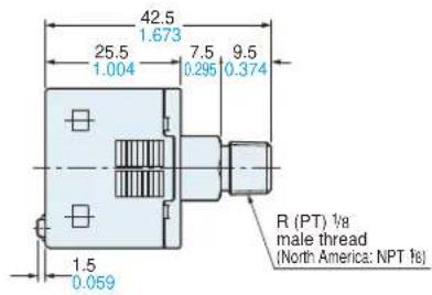
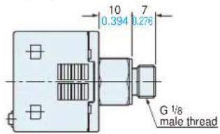
| Pressure port | Asia: M5 female thread + R (PT) 1⁄2 male thread [excluding DP-1-M(-P)], Europe: M5 female thread + G 1⁄2 male thread, North America: M5 female thread + NPT 1⁄2 male thread | ||||
| Material | Enclosure: PBT (glass fiber reinforced), LCD display: Acrylic, Pressure port: Stainless steel (SUS303), Mounting threaded part: Brass (nickel plated), Switch part: Silicone rubber | ||||
| Connecting method / Cable length | Connector / Total length up to 100 m 328.084 ft (less than 30 m 98.425 ft when conforming to CE marking) is possible with 0.3 mm, or more, cable | ||||
| Weight | Net weight: 40 g approx. (DP-10-C-M(-P): 30 g approx.), Gross weight: 135 g approx. (DP-10-C-M(-P):125 g approx.) | ||||
| Accessories | CN-14A-C2 (Connector attached cable 2 m 6.562 ft): 1pc. (excluding M8 plug-in connector type) | ||||
Notes: 1) Where measurement conditions have not been specified precisely, the conditions used were an ambient temperature of +20 °C +68 °F.
2) Model Nos. of Asia type having "-M" are short pressure port type. Model Nos. of Asia and North America types having the suffix "-P" are PNP output type.
3) Cannot be used at the same time.
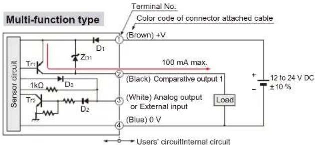
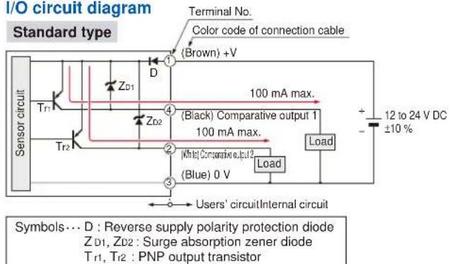
I/O CIRCUIT AND WIRING DIAGRAMS
DP-10□
NPN output type
I/O circuit diagram
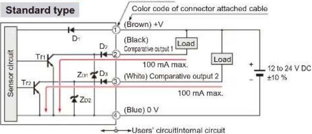
Symbols… D : Reverse supply polarity protection diode ZD1, ZD2 : Surge absorption zener diode Tr1, Tr2 : NPN output transistor
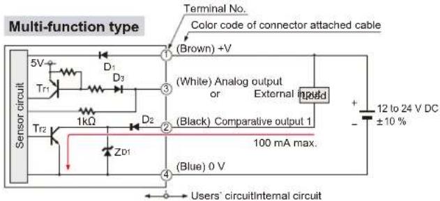
Symbols… D1, D2 : Reverse supply polarity protection diode ZD1 : Surge absorption zener diode Tr1 : PNP input transistor Tr2 : NPN output transistor
Terminal arrangement diagram
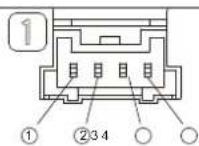
| Terminal | Designation |
| 1 | +V |
| 2 | Comparative output 1 |
| 3 | Standard type: Comparative output 2Multi-function type: Analog output or External input |
| 4 | 0 V |
DP-10□-P
PNP output type
I/O circuit diagram
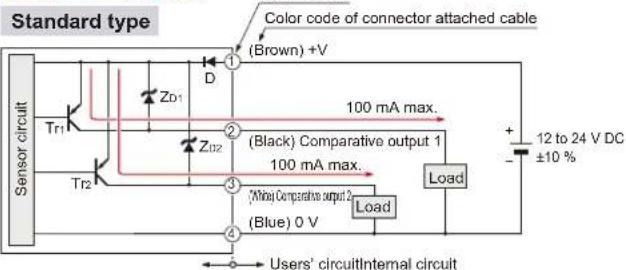
Symbols… D : Reverse supply polarity protection diode ZD1, ZD2 : Surge absorption zener diode Tr1, Tr2 : PNP output transistor
Symbols… D1, D2 : Reverse supply polarity protection diode ZD1: Surge absorption zener diode Tr1: PNP output transistor Tr2: NPN input transistor
Terminal arrangement diagram
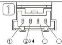
| Terminal | Designation |
| 1 | +V |
| 2 | Comparative output 1 |
| 3 | Standard type: Comparative output 2Multi-function type: Analog output or External input |
| 4 | 0 V |
I/O CIRCUIT AND WIRING DIAGRAMS
DP-11□-E-P-J PNP output type
I/O circuit diagram
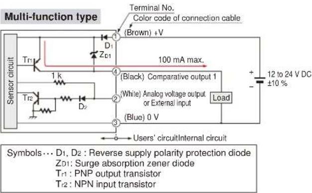
Terminal arrangement diagram
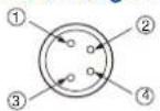
| Terminal | Designation |
| 1 | +V |
| 2 | Standard type: Comparative output 2Multi-function type: Analog output or External input |
| 3 | 0 V |
| 4 | Comparative output 1 |
PRECAUTIONS FOR PROPER USE

- Never use this product as a sensing device for personnel protection.
- In case of using sensing devices for personnel protection, use products which meet laws and standards, such as OSHA, ANSI or IEC etc., for personnel protection applicable in each region or country.
- The DP-100 series is designed for use with non-corrosive gas. It cannot be used with liquid or corrosive gas.
Wiring
- Make sure that the power supply is off while wiring.
- Verify that the supply voltage variation is within the rating.
- If power is supplied from a commercial switching regulator, ensure that the frame ground (F.G.) terminal of the power supply is connected to an actual ground.
- In case noise generating equipment (switching regulator, inverter motor, etc.) is used in the vicinity of this sensor, connect the frame ground (F.G.) terminal of the equipment to an actual ground.
- Do not run the wires together with high-voltage lines or power lines or put them in the same raceway. This can cause malfunction due to induction.
- Incorrect wiring will cause problems with operation.
Connection
- Do not apply stress directly to the connection cable leader or to the connector.
![Connector attached cable [CN-14A(-R)-C□]](/content/2026/05/1010944/images/3f80589de7c3b24d887725a63c89bcaf20976a18918f7dbbcb7318df1c86635c.jpg)
Conditions in use for CE conformity
- The DP-100 series is a CE conformity product complying with EMC Directive. The harmonized standard with regard to immunity that applies to this product is EN 61000-6-2 and the following condition must be met to conform to that standard.
Condition
- The line to connect with this sensor should be less than 30 m 98.425 ft.
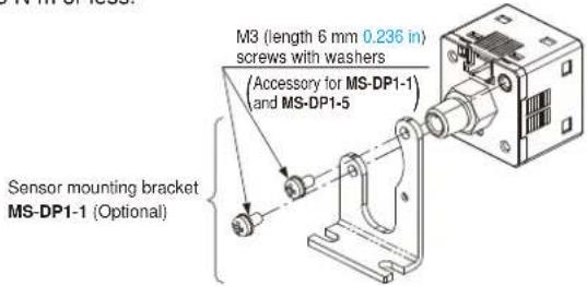
Mounting
- MS-DP1-1/MS-DP1-5 sensor mounting brackets are available separately, and it should be used for mounting. When tightening the sensor to the sensor mounting bracket, use a tightening torque of 0.5 N·m or less.
- The MS-DP1-2 panel mounting bracket (optional) and the MS-DP1-3 front protection cover (optional) are also available.
PRECAUTIONS FOR PROPER USE
- The MS-DP1-4 panel mounting bracket is available when switching from the DP2 / DP3 series.
flowchart
graph TD
    A["Front protective cover DPX-04 (Optional) can be installed on MS-DP1-4."] --> B["DC"]
    B --> C["DP2 / DP3"]
    C --> D["Remove"]
    D --> E["Mounting holes for DP2 / DP3 series can be used as is."]
    E --> F["Remove"]
    F --> G["Drop"]
    G --> H["Panel mounting bracket MS-DP1-4"]
    I["DP-100"] --> J["Drop"]
    J --> K["Mounting holes for DP2 / DP3 series can be used as is."]
- An conversion bushing is available for when using the DP-10-M short pressure port type. It can be used to switch between this model and the DP2 / DP3 series. When connecting to the pressure port, use a tightening torque of 1.0 N·m or less. M5 female thread Bc/4 female thread
- The MS-DP1-F□ flat attachment is available.
If using the MS-DP1-F□ flat attachment (optional), install by following the procedures given below.
①Decide the direction of this product to mount with the sensor.
Pressure port faces downward

Pressure port faces rightward
Note: It is not possible to mount this product such that the pressure port faces upward.
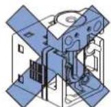
②Mount this product with the M3 female threads of the sensor by using the attached M3 (length 8 mm 0.315 in) screws. The tightening torque should be 0.5 N·m or less.
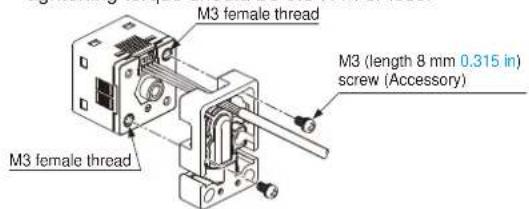
③Mount this product with the mounting surface by using the attached M4 (length 20 mm 0.787 in) screws. The tightening torque should be 1.2 N·m or less.
Note: Take care that if the cable with connector is sticking out of the side groove of this product when mounting, the cable may disconnected.
PipingMounting
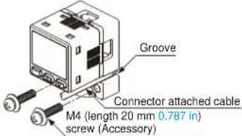
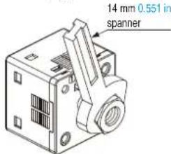
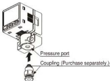
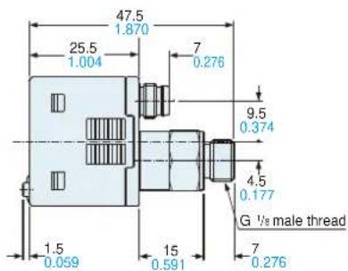
- If connecting a commercially-available coupling to the pressure port, attach a 12 mm 0.472 in spanner (14 mm 0.551 in spanner for DP-100-E type) to the hexagonal section of the pressure port to secure it, and tighten at a torque of 9.8 N·m or less. If it is tightened using excessive torque, it may damage the coupling or the pressure port. In addition, wrap sealing tape around the coupling when connecting it to prevent leaks.
- If connecting a commercially-available joint to the pressure port of the DP-10□-M, hold the main unit in your hand to steady it, and tighten to a torque of 1.0 N·m or less. If it is tightened to an excessive torque, the joint or the main unit may become damaged.
- If connecting a commercially-available joint to the pressure port of the MS-DP1-7, tighten to a torque of 9.8 ~N · m or less.
- The tightening torque should be 1 N·m or less when connecting a coupling to the pressure port of MS-DP1-FM.
- When connecting the coupling to the pressure port of MS-DP1-FR/FE/FN, hold the pressure port with a 14 mm 0.551 in spanner and make sure that the tightening torque is 9.8 N·m or less. In addition, in order to prevent any leakage, wind a sealing tape on the coupling when connecting.
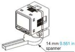
Note: Do not tighten the pressure port by holding the product with the spanner. It may cause the product breakage.
Flat attachment
- Make sure to mount MS-DP1-F□ with the sensor properly. If it is not mounted properly, air leakage may occur.
• Take care that the excessive mounting and dismounting of this product may cause deterioration of the O-ring. - If you touch the O-ring of MS-DP1-F□, or any scratch or dust, etc. is attached to it, air leakage may occur and the sensing performance may deteriorate.
Take sufficient care when using and storing MS-DP1-F□.
PRECAUTIONS FOR PROPER USE
Others
• This product has been developed / produced for industrial use.
- Use within the rated pressure range.
- Do not apply pressure exceeding the pressure withstandability value. The diaphragm will get damaged and correct operation shall not be maintained.
- Do not use during the initial transient time (0.5 sec. approx.) after the power supply is switched on.
- Avoid dust, dirt, and steam.
• Take care that the sensor does not come in direct contact with water, oil, grease, or organic solvents, such as, thinner, etc.
- Do not insert wires, etc., into the pressure port. The diaphragm will get damaged and correct operation shall not be maintained.
- Do not operate the keys with pointed or sharp objects.
RUN mode
• This is the normal operating mode.
| Setting item Description | |
| Threshold value setting | The threshold values for ON / OFF operation can be changed directly by pressing the increment key (UP) and the decrement key (DOWN). |
| Zero-adjustment function | This forces the pressure value display to be reset to zero when the pressure port is open on the atmospheric pressure side. |
| Key lock function | Stops key operations from being accepted. |
| Peak hold / bottom hold function | Displays the peak value and bottom value for fluctuating pressure. The peak value appears in the main display, and the bottom value appears in the sub display. |
MENU SETTING mode
- If the mode selection key is pressed and held for 2 seconds in RUN mode, the mode will switch to MENU SETTING mode.
- If the mode selection key is pressed while a setting is being made, the mode will switch to RUN mode. In this case, the settings that have been changed will be entered.
| Setting item Description | |
| Comparative output 1 output mode setting | Sets the output mode for comparative output 1. |
| Comparative output 2 output mode setting (standard type only) | Sets the output mode for comparative output 2. |
| Analog output / external input switching (multi-function type only) | Allows switching between analog voltage output / analog current output, and auto-reference input / remote zero-adjust-ment input. |
| NO / NC switching | Sets normally open (NO) or normally closed (NC). |
| Response time setting | Sets the response time.The response time can be selected from 2.5 ms, 5 ms, 10 ms, 25 ms, 50 ms, 100 ms, 250 ms, 500 ms, 1,000 ms and 5,000 ms. |
| Display color switching for main display | Allows the color for the main display to be changed.The colors can be set to 'red / green' or 'green / red' to correspond to ON / OFF output, or it can be fixed at 'red' or 'green' all the time. |
| Unit switching | Pressure unit can be changed. |
PRO mode
- If the mode selection key is pressed and held for 5 seconds in RUN mode, the mode will switch to PRO mode.
- If the mode selection key is pressed while a setting is being made, the mode will switch to RUN mode. In this case, the settings that have been changed will be entered.
| Setting item Description | |
| Sub display switching | Changes the information in the sub display during RUN mode operation to the desired alphanumeric display. |
| Display refresh rate switching | Changes the display refresh rate for the pressure value displayed in the main display. |
| Hysteresis fix value switching | Sets the hysteresis for EASY mode and window comparator mode. (8 steps) |
| Linked display color switching (standard type only) | Allows the display color for the main display to be switched in line with the output operation for comparative output 1 or comparative output 2. |
| ECO mode setting | Allows power consumption to be reduced by dimming the display or turning it off. |
| Setting check code | Allows the setting details to be checked via codes. |
| Setting copy mode | Allows the setting details for the master sensor to be copied to slave sensors. |
| Reset setting | Resets the settings to the factory settings. |
Table of codes
| Code | 1st digit | 2nd digit | 3rd digit | 4th digit | ||||
| Standard type | Multi-function type | |||||||
| Comparative output 1 output mode | NO / NC switching | Comparative output 2 output mode | NO / NC switching | Analog voltage output 1 external input | Threshold value display | Display color for main display | Display color linking | |
| 0 | EASY | NO | OFF | OFF | Analog voltage output | P-1, Lo-1 | Red when ON | Comparative output 1 |
| 1 | NC | EASY | NO | Auto-reference | Hi-1 | Comparative output 2 | ||
| 2 | Hysteresis | NO | NC | Remote zero-adjustment | P-2, Lo-2 | Green when ON | Comparative output 1 | |
| 3 | NC | Hysteresis | NO | Analog current output | Hi-2 | Comparative output 2 | ||
| 4 | Window comparator | NO | NC | — | ADJ. | Always red | Comparative output 1 | |
| 5 | NC | Window comparator | NO | — | — | Comparative output 2 | ||
| 6 | — | — | NC | — | — | Always green | Comparative output 1 | |
| 7 | — | — | — | — | — | — | Comparative output 2 | |
| Code | 5th digit 6th digit 7th digit 8th digit | |||
| Response time Unit switching | Display refresh rate | ECO mode | ||
| 0 | 2.5 ms MPa | 250 ms OFF | ||
| 1 | 5 ms kPa | 500 ms STD | ||
| 2 | 10 ms kgf/cm | 2 | 1,000 ms FULL | |
| 3 | 25 ms bar | — | — | |
| 4 | 50 ms psi | — | — | |
| 5 | 100 ms mmHg | — | — | |
| 6 | 250 ms inchHg | — | — | |
| 7 | 500 ms | — | — | — |
| 8 | 1,000 ms | — | — | — |
| 9 | 5,000 ms | — | — | — |
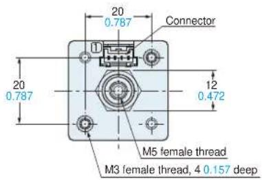
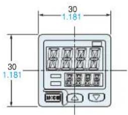
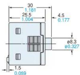
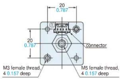
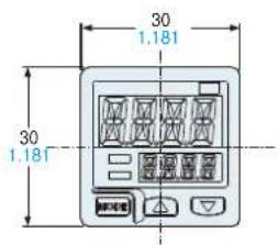
DP-10□ Sensor
Europe
Europe
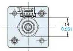
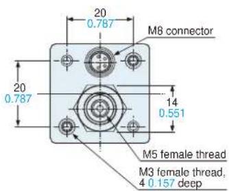
DP-10□-M(-P) Sensor
DP-11□-E-P-J Sensor
MS-DP1-1
Sensor mounting bracket (Optional)
Two M3 (length 6 mm 0.236 in) screws with washers are attached.
Assembly dimensions
Mounting drawing with DP-10□
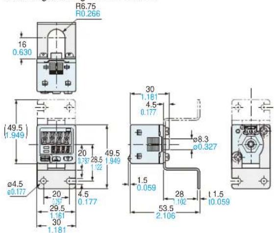
MS-DP1-5
Sensor mounting bracket (Optional)

Material: Cold rolled carbon steel (SPCC)
(Uni-chrome plated)
Two M3 (length 6 mm 0.236 in) screws with washers are attached.
Assembly dimensions
Mounting drawing with DP-10□-M
Panel mounting bracket (Optional), Front protection cover (Optional)
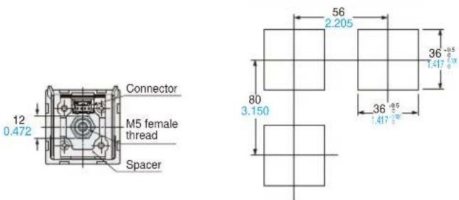
MS-DP1-2
Assembly dimensions
Mounting drawing with DP-10
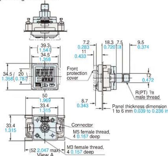
Material: POM (Panel mounting bracket)
Polycarbonate (Front protection cover)
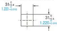
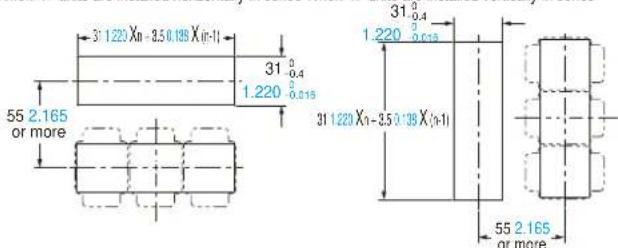
Panel cut-out dimensions
When 1 unit is installed
When "n" units are installed horizontally in series When "n" units are installed vertically in series
Note: The panel thickness should be 1 to 6 mm 0.039 to 0.236 in.
Note: The panel thickness should be 1 to 6 mm 0.039 to 0.236 in.
MS-DP1-4
Panel mounting bracket (Optional)
Assembly dimensions
Mounting drawing with DP-10☐
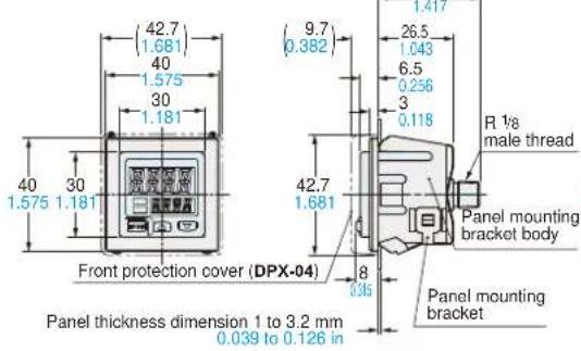
Panel cut-out dimensions
Note: The panel thickness should be 1 to 32 mm 0.039 to 1.260 in.
Material: Panel mounting bracket body ... Nylon 6
Panel mounting bracket ... Stainless steel (SUS304)
Spacer ... Cold rolled carbon steel (SPCC)(Uni-chrome plated)
MS-DP1-7
Conversion bushing (Optional)
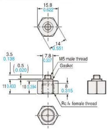
Material: Brass (Nickel plated)
Weight: 10 g approx.
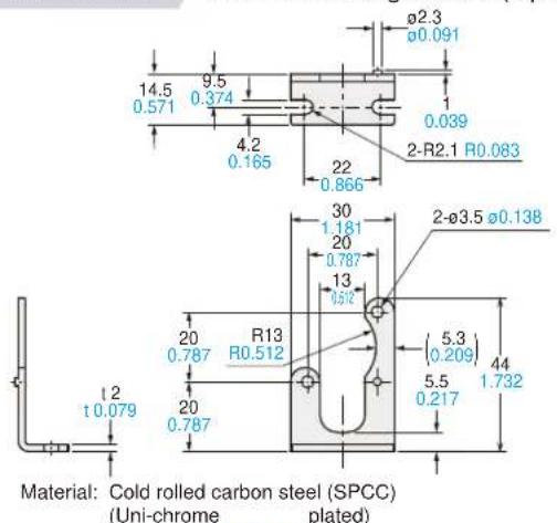
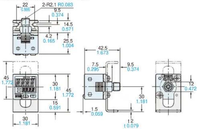
MS-DP1-FM
Flat attachment (Optional)
Assembly dimensions
Mounting drawing with DP-10□-M
Weight: 15 g approx. (flat attachment only)
Two M3 (length 8 mm 0.315 in) screws, two M4 (length 20 mm 0.787 in) screws are attached.
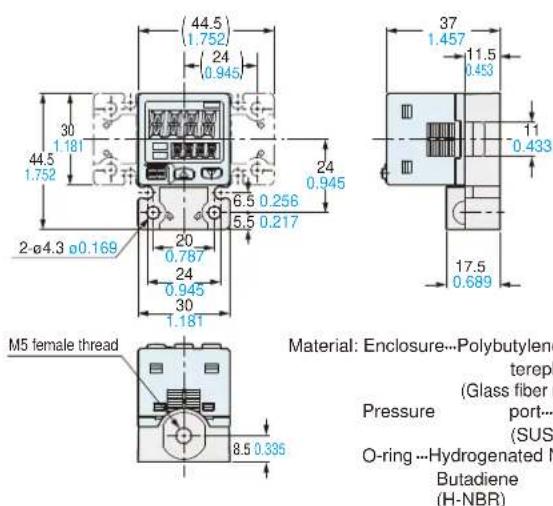
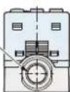
MS-DP1-FR/FN/FE
Flat attachment (Optional)
Assembly dimensions
Mounting drawing with DP-10□-M
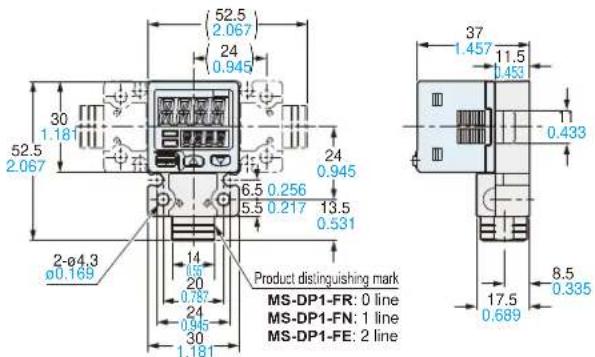
Pre(b)
G ^1 /is female thread (Note)
Note: MS-DP1-FR has a
Rct/s female thread.
MS-DP1-FN has a
NPT 1/8 female thread.
Material: Enclosure---Polybutylene terephthalate (PBT) (Glass fiber reinforced)
Pressure port... Stainless steel (SUS303)
O-ring…Hydrogenated Nitrile
Butadiene Rubber (H-NBR)
Weight: 25 g approx. (flat attachment only)
Two M3 (length 8 mm 0.315 in) screws, two M4 (length 20 mm 0.787 in) screws are attached.
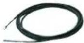
CN-14A(-R)-C□ Connector attached cable (Optional, CN-14A-C2 is attached to the sensor)
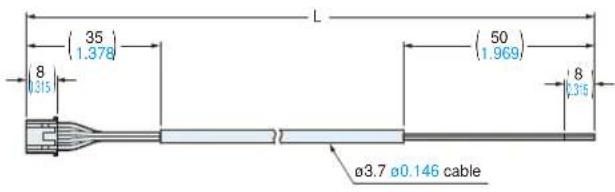
| Model No. Cable | length L (mm in) |
| CN-14A(-R)-C1 | 1,000 39.370 |
| CN-14A(-R)-C2 | 2,000 78.740 |
| CN-14A(-R)-C3 | 3,000 118.110 |
| CN-14A(-R)-C5 | 5,000 196.850 |
Please contact ......
Panasonic Industrial Devices SUNX Co., Ltd.
2431-1 Ushiyama-cho, Kasugai-shi, Aichi, 486-0901, Japan
Global Sales Department
■Telephone: +81-568-33-7861 ■Facsimile: +81-568-33-8591
panasonic.net/id/pidsx/global
Panasonic®
All Rights Reserved ©Panasonic Industrial Devices SUNX Co., Ltd. 2013
