
TLF 1000 - Thermostat H-Tronic - Free user manual and instructions
Find the device manual for free TLF 1000 H-Tronic in PDF.


| Product Type | Temperature and humidity switch with 4 potential-free relay outputs |
| Model | TLF 1000 |
| Brand | H-Tronic |
| Operating Voltage | 230 V/AC (50 Hz) |
| Power Consumption (Standby) | approx. 1 W |
| Output / Max Switching Capacity | 4 potential-free relays; resistive: 250 V/AC 12 A, 2700 VA; inductive: 250 V/AC 5 A, 1250 VA |
| Temperature Measuring Range | -25 °C to +70 °C |
| Humidity Measuring Range | 0% to 100% RH |
| Temperature Accuracy | ±0.3 °C (5-60 °C), ±0.7 °C (-25 to +5 °C), ±0.9 °C (60-70 °C) |
| Humidity Accuracy | ±3% RH (20-80% RH), ±4.5% RH (0-20% and 80-100% RH) |
| Resolution / Setting | 0.1 °C, 0.1% RH, 1 s |
| Sensor | TH-1 (included), cable 10 m extendable up to 50 m |
| Dimensions (Main Unit) | 170 x 140 x 68 mm |
| Dimensions (Sensor) | 67 x 36 x 23 mm |
| Operating Temperature | -10 °C to +50 °C |
| IP Rating | IP20 |
| Mounting | Wall mounting or DIN rail (35 mm) |
| Display | Illuminated LC display showing temperature and humidity |
| Control Modes | Cooling, heating, dehumidifying, humidifying with settable setpoints and differentials |
| Delay Settings | Switch-on delays for each relay (0-600 s) |
| Sensor Monitoring | Error LED if sensor is disconnected or defective |
| Special Features | AND/OR logic for relay outputs; remote sensing up to 50 m |
Frequently Asked Questions - TLF 1000 H-Tronic
User questions about TLF 1000 H-Tronic
0 question about this device. Answer the ones you know or ask your own.
Ask a new question about this device
Download the instructions for your Thermostat in PDF format for free! Find your manual TLF 1000 - H-Tronic and take your electronic device back in hand. On this page are published all the documents necessary for the use of your device. TLF 1000 by H-Tronic.
USER MANUAL TLF 1000 H-Tronic
- Designated use 25
- Specifications 25
- Definition of terms....26
- Safety instructions....26
- General installation instructions .... 28
- Control and Display....32
- Menu of the device 32
- Connection of the sensor 38
- Usage Examples/Settings 39
- General information and information 40
- Guarantee....41
- Instruction for the Environment....43
TEMPERATUR- LUFTFEUCHTESCHALTER TLF1000
Art.-Nr. 1114660
KELLERMONTAGE (SENSOR)
The TLF1000 temperature/humidity switch with four potential-free relay outputs measures the temperature and relative humidity with the connected TH-1 sensor. Based on these values, switching points at different humidity values and temperatures can be programmed. Room fans for supply and exhaust air can be controlled directly via 4 integrated potential-free relays. In addition, various devices, which are used for heating, cooling, dehumidifying or humidifying, can be switched at designated values. Typical applications include temperature control in heating or cooling, temperature and humidity measurement, and room drying or dehumidifying.
CHARACTERISTICS
- Automatic control of "Cooling - Heating" or "Dehumidifying - Humidifying"
- Automatic humidity control for bathrooms, sanitary rooms, cellars, wine cellars, kitchens, etc.
- Direct control of room fans and other consumers via 4 potential-free relays
- Control through set value and its difference value
- Set value or difference value at 0.1 increments
- Remote measurement possible up to 50 m
– Sensor monitoring for interruption of sensor line - Illuminated LC display
- High-quality, long-term stable sensor included
- Dimensions wall housing: 170 x 140 x 68 mm
- Dimension sensor housing: 67 x 37 x 22 mm
1. DESIGNATED USE
The temperature-humidity switch TLF1000 measures the temperature and the relative humidity with theTH-1 sensor. Based on these values, switching points at different humidity values and temperatures can be programmed. Room fans for supply and exhaust air can be controlled directly via 4 integrated potential-free relays. Typical applications include the measurement of temperature and humidity, automatic ventilation, drying or humidifying rooms, the manual control of room fans with the use of a temperature and humidity switch.
2. SPECIFICATIONS
- Operating voltage: 230 V/AC (50 Hz)
– Power consumption (standby): approx. 1 W - Output/max. Switching capacity: 4 potential-free relays
Resistive loads: 250 V / AC / 12 A / 2700 VA 24V DC / 12A
Inductive loads: 250 V / AC / 5 A / 1250 VA 24 V / DC / 5 A - Resolution/Setting: 0.1 °C, 0.1 % RH, 1 s
- Temperature measuring range: -25 °C to +70 °C
- Humidity measuring range: 0% RH to 100% RH
Accuracy: 0% RH to 20% RH (max +/- 4.5% RH) - Sensor: TH-1 sensor
- Sensor cable: 10m (extendable up to 50m)
- Dimensions (TLF1000): 170 x 140 x 68 mm
- Dimensions (sensor TH-1): 67 x 36 x 23 mm
- Operating temperature: -10 °C to +50 °C
- IP-class: IP20
$$ \begin{array}{l} \text { Accuracy: } - 2 5 ^ {\circ} \mathrm{C} \text { to } + 5 ^ {\circ} \mathrm{C} (\max + / - 0, 7 ^ {\circ} \mathrm{C}) \ + 5 ^ {\circ} \mathrm{C} \text { to } 6 0 ^ {\circ} \mathrm{C} (+ / - 0. 3 ^ {\circ} \mathrm{C}) \ + 6 0 ^ {\circ} \mathrm{C} \text { to } 7 0 ^ {\circ} \mathrm{C} (\max + / - 0. 9 ^ {\circ} \mathrm{C}) \ \end{array} $$
$$ 20\% \text{RH to } 80\% \text{RH (+/-} 3\% \text{RH)} $$
$$ 80 \% \text{RH to } 100 \% \text{RH (max} +/- 4.5 \% \text{RH)} $$
3. DEFINITION OF TERMS
HUMIDITY
Humidity is the proportion of water vapor in the air.
DEW POINT/DEW POINT TEMPERATURE
The dew point or the dew point temperature is the temperature at which the airborne water vapour will condense to form liquid water.
ABSOLUTE HUMIDITY
The absolute humidity is the proportion of water vapor and is expressed in grams per cubic meter (g/m ^3 ).
Values between 0 g/m^3 and a maximum value, depending directly on the air temperature, are possible. When the maximum humidity is exceeded, some of the water will condense, often the cause of damp room walls. Condensation can also occur if the air temperature is cooled and the maximum humidity value falls below the actual humidity.
RELATIVE HUMIDITY
The relative humidity indicates to what percentage the absolute humidity exhausts the maximum humidity level. If a relative humidity of 100% is exceeded, the excess moisture can cause, e.g. condensation.
4. SAFETY INSTRUCTIONS
PLEASE FOLLOW THESE INSTRUCTIONS BEFORE USING
THE DEVICE:
Please read this manual thoroughly before use. By reading this manual you will get to know all functional options, avoid incorrect operation and protect yourself and your device from possible damage. The law requires us to provide you with important safety notices and to advise you on how to avoid damage to persons and the equipment. Keep the instructions for future reference.
- The device is part of a building installation. When planning and installing electrical systems, follow the relevant standards and guidelines of the country laws in which the system is installed.
- Installation, mounting and wiring of electrical devices as well as work on the 230 V mains may only be carried out by a qualified electrician (in
accordance with VDE 0100). In the process, the applicable accident prevention regulations must be followed.
- When handling products that come into contact with electrical voltage, the valid VDE regulations must be followed, in particular VDE 0100, VDE 0550/0551, VDE 0700, VDE 0711 and VDE 0860.
- Opening the device involves the risk of electric shock! To avoid an electric shock, disconnect mains voltage before working on the device (switch off circuit breaker, secure against restart).
- Installation, service and repair work may only be carried out by authorized personnel. Only original spare parts may be used. The use of foreign spare parts can cause considerable damage and personal injury!
- Tools may not be used on the device, components or accessories unless it is ensured that the equipment is disconnected from the mains and any electrical charges stored in the devices components have been previously discharged.
- Operation of the device is only permitted at 230 V/AC/50 Hz AC.
- Check the device and the connected cables used for possible damage before each use. If you notice any damage to the device (eg transport damage), do not operate the device. Damaged connecting cables must be replaced immediately. In this case, bring the device to a specialist workshop.
- The device may only be operated indoors (with the exception of the humidity sensors TH-1) and the influence of moisture, dust, sunshine or other thermal radiation must be avoided.
- Do not operate the device under adverse environmental conditions; this should be avoided at all costs. Adverse conditions are: ambient temperatures above 50^ , flammable gases, solvents, vapors, dust, humidity above 80% rel. humidity (excluding the moisture sensors TH-1), as well as moisture.
- Do not operate the device near open flames or other sources of heat (heating, gas ovens or in strong sunlight).
- Do not connect external devices exceeding the specified power limit. An overload can lead to the destruction of the device, to a fire or an electric accident.
-
This device is not intended for use by persons (including children) who have diminished physical, sensory or mental abilities or lack of experience or knowledge unless they are supervised by a person responsible for their safety when using the device.
-
The device may only be stored and used outside the reach of children. Children are not allowed to play with the device.
- Do not leave the packing material laying around. This could become a dangerous toy for children. Therefore, dispose of unnecessary packaging material or store it in a place that is inaccessible to children. There is danger of suffocation!
- The device may only be passed on to third parties together with the operating instructions.
Please follow the following installation and usage instructions to avoid malfunctions, damage and health problems. If the safety instructions and the instructions for proper handling in this operating manual are deliberately or negligently disregarded, there is a danger of damages, short circuit, fire, explosion or electric shock. For safety and licensing reasons (CE), the product may not be changed. In these cases, we assume no liability for personal injury, property damage or consequential damage. In addition, the warranty/guarantee will expire.
5. GENERAL INSTALLATION INSTRUCTIONS
FOLLOW THE FOLLOWING ADVICE WHEN CONNECTING AND INSTALLING THE DEVICE:
- Before starting installation or before working on the device, the device must be disconnected from the power supply (230 V/50 Hz) and secured against switching it on.
- Check that the device is free of all charges before starting to assemble or work on it.
- Use only parts that are included with the product or are definitely described as accessories!
- When controlling a load that can cause a hazard to people in the event of a fault, additional safety measures are required.
-
Carefully plan the wiring when connecting to other devices (eg PC). Under certain circumstances, internal connections to third-party devices (eg connection GND with protective earth) can lead to unwanted voltage potentials.
-
The product is designed for direct mounting on dry and clean walls and on DIN top hat rails (35mm).
- When laying the cables, it is important to ensure a separation of signal cables and interfering external cables. If electromagnetic interference is expected, use a shielded and/or twisted cable.
- If surges can be expected, install a surge protection.
INDIVIDUAL ASSEMBLY STEPS
- Open the housing by unscrewing the screw near the cable inputs and lifting the cover of the housing.
- Mark and drill the holes for mounting according to the holes on the back of the base. Pay attention to the position of the mains line. When drilling, check that there are no electrical lines in the immediate area of the mounting holes.
- Fix the housing to the wall with sufficiently dimensioned mounting material adapted to the material of the wall.
- Insert the cables through the cable openings in the housing (cables must be attached to the wall).
- The TLF1000 has various possibilities of cable feedthroughs. The possible cable entry holes are marked as predetermined breaking points on the housing and can be broken or drilled out accordingly with a drill.
- Only operate the device with the housing closed and secured.
DIN RAIL MOUNTING
- The device can be mounted and fastened sidewise or frontal onto a DIN rail (35 mm. The DIN rail mounting is located on the back of the device.
- To unlock, open the screw in the area of the cable entries and lift off the housing cover. Open the DIN rail lock with a flat-head screwdriver and lift the device off the DIN rail.
ELECTRICAL CONNECTION
- Open the housing cover by opening the screw near the cable entries and lifting the housing cover.
- For the electrical connection, connect the black or brown wire of the mains
supply cable to terminal L and the blue wire (neutral conductor) to terminal N. According to VDE 100 the electrical connection must be installed as a permanent connection.
- For safety reasons, make sure that only equal voltages are switched at the relay contacts (eg not Rel. 1: 12 V and Rel. 2: 230 V). The device is designed for appliance class II. Please make sure that to your connected devices without appliance class II have connected protective conductors according to VDE.
- The relay contacts work as potential-free changeover contacts and must be wired according to the application. Consumers (eg fans) must each be protected with their own fuse according to their specifications.
- Connect the humidity sensor TH-1 with the correct polarity to the connector strip (sensor).
- After the assembly of the wiring, fix all cables in the housing with strain reliefs.
- Replace the lid by snapping it in place and tightening the screw in the area of the cable entries.
ASSEMBLY IN THE BASEMENT (SENSOR)
In a basement, the difference between the air temperature in the room and the wall temperature can be up to 3 °C , as the earth-contacting walls (outer walls) are usually colder. In order to measure correct room temperatures there should be a gap between wall and sensor TH-1 of approx. 1–2 cm when mounted. During operation, a blue LED on the TH-1 sensor flashes.
OUTDOOR INSTALLATION (SENSOR)
If the sensor is used as an outdoor sensor, it should be mounted on the sun- or rain-protected north side of the house.

IMPORTANT! If the sensor is mounted in the area of possible direct sunlight (eg south side), avoid the direct sunlight by placing a shade over the sensor as this will otherwise lead to incorrect measurements. Mount the sensor protected from the weather to ensure a long service life.
DISPLAY BOARD/SENSOR ATTACHMENT
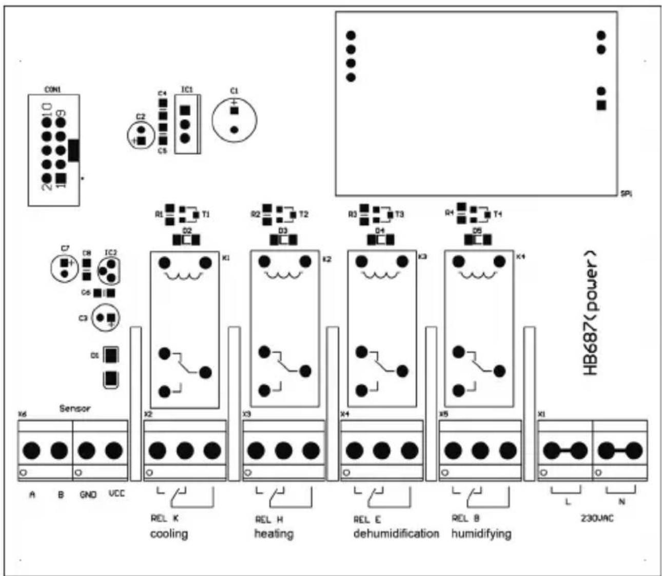
Terminal assignment:
Sensor = sensor input
REL K = relay temperature (cooling)
REL H = relay temperature (heating)
REL E = Relay humidity sensor (dehumidification)
REL B = Relay humidity sensor (humidifying)
Terminal 230 V/AC = Supply voltage 230 V/AC (50 Hz)
6. CONTROL AND DISPLAYS
LEDS
■ COOLING ON: The cooling relay is switched on
■ HEATING ON: The heating relay is switched on
■ DEHUMIDIFY: The dehumidification relay is switched on
■ HUMIDIFY: The humidify relay is switched on
■ ERROR: The sensor TH-1 is not connected or defective
KEYS
■ KEY SET: Confirm or select a value
■ KEY ▲: Increase the desired value or scroll up
■ KEY ▲: Reduce the desired value or scroll down
7. MEN U
When the SET button is pressed, the unit enters the setting mode.
Note 1: The ↓ symbol for the SET key is displayed on the LCD. The symbol ↑ is responsible for the ▲▼ keys. If these symbols are displayed on the LC display, these values can be changed or viewed via the keys.
Note 2: If the unit is in setting mode and no key is pressed for more than 10 seconds, the setting mode will automatically be cancelled and the display mode will change. All changes made up to that point are saved.
7.1 T SET
T SET
25.0°C ↑ ↓ Factory setting
Here the set-point value for the temperature is set. The value can be changed with the ▲▼ keys. When the setting is completed, this is confirmed with the SET button. The device will then show the next menu item.
Setting range: -40...120 °C
7.2 T-DIFF KÜHLEN (COOLING)
T-DIFF KÜHLEN
2.0°C ↑ ↓ Factory setting
Here the switch-on difference for the „Cooling“ function is set. The value can be changed with the ▲▼ keys. When the setting is completed, this is confirmed with the SET button. The device will then show the next menu item.
Setting range: 0.1...15 °C
The relay „Cooling“ (REL K) is switched on if:
Temperature ≥ (T_set + T_diff_cooling)
The relay „Cooling“ (REL K) is switched off when:
Temperature ≤ T_set
7.3 T-DIFF HEIZEN (HEATING)
T-DIFF HEIZEN
2.0°C ↑ ↓ Factory setting
Here the switch-on difference for the „Heating“ function is set. The value can be changed with the ▲▼ keys. When the setting is completed, this is confirmed with the SET button. The device will then show the next menu item.
Setting range: 0.1...15 °C
The relay „Heating“ (REL H) is switched on, if:
Temperature ≤ (T_set - T_diff_heating)
The relay „Heating“ (REL H) is switched off when:
Temperature ≥ T_set
7.4 DELAY REL. KÜHL. (COOLING)
DELAY REL. KÜHL.
0.0 SEC ↓ ↓ Factory setting
Here the switch-on delay for the relay „Cooling“ is set. The value can be changed with the ▲▼ keys. When the setting is completed, this is confirmed with the SET button. The device will then show the next menu item.
Setting range: 0...600 sec.
7.5 DELAY REL. HEIZEN (HEATING)
DELAY REL. HEIZEN
0.0 SEC ↑ ↓ Factory setting
Here the switch-on delay for the „Heating“ relay is set. The value can be changed with the ▲▼ keys. When the setting is completed, this is confirmed with the SET button. The device will then show the next menu item.
Setting range: 0...600 sec.
7.6 F SET
F SET
50 % ↑ ↓ Factory setting
Here the set value for the relative humidity is set. The value can be changed with the ▲▼ keys. When the setting is completed, this is confirmed with the SET button. The device will then show the next menu item.
Setting range: 0...100% RH
7.7 F-DIFF ENTF.
F-DIFF ENTF.
5.0 % ↑ ↓ Factory setting
Here the switch-on difference for the function „Dehumidify“ is set. The value can be changed with the ▲▼ keys. When the setting is completed, this is confirmed with the SET button. The device will then show the next menu item.
Setting range: 0.1...20% RH
The „Dehumidify“ relay (REL E) is switched on when: Humidity ≥ (F_set + T_diff_dwet)
The „Dehumidify“ relay (REL E) is switched off when: Humidity ≤ F_set
7.8 F-DIFF BEFEUCHT. (HUMIDIFIED)
| F-DIFF BEFEUCHT. |
| 5.0 % ↑ ↓ Factory setting |
Here the switch-on difference for the „humidifying“ function is set. The value can be changed with the ▲▼ keys. When the setting is completed, this is confirmed with the SET button. The device will then show the next menu item.
Setting range: 0.1...20% RH
The „Humidify“ relay (REL B) is switched on if: Humidity ≤ (F_set - T_diff_befeuchten)
The „Humidify“ relay (REL B) is switched off when: Humidity ≥ F_set
7.9 DELAY REL. ENTF.
DELAY REL. ENTF.
0.0 SEC ↑ ↓ Factory setting
Here the switch-on delay for the „Humidify“ relay is set. The value can be changed with the ▲▼ keys. When the setting is completed, this is confirmed with the SET button. The device will then show the next menu item.
Setting range: 0...600 sec.
7.10 DELAY REL. BEF.
DELAY REL. BEF.
0.0 SEC ↑ ↓ Factory setting
Here the switch-on delay for the „Humidify“ relay is set. The value can be changed with the ▲▼ keys. When the setting is completed, this is confirmed with the SET button.
Setting range: 0...600 sec.
After this menu item, the device changes to the display mode. Two parameters are displayed: the measured temperature and relative humidity.
Example:
T = 22.5°C
F = 35.7%RH
8. CONNECTING THE SENSOR
The sensor is connected to the „Sensor“ socket as shown under „Display board/sensor mounting“ (page 31).
| Name (board) Colour codingferrule (sensor) | |
| A WHITE | |
| B GRAY or YELLOW | |
| GND BLACK | |
| VCC RED | |
If necessary, the cable of the sensor can be extended up to 50m. The longer the extension cable, the larger the cross section of the individual wires should be. When laying the sensor cable, it is essential to ensure that it is not lying near sources of interference (power lines, magnetic fields).
9. EXAMPLES OF USE/SETTINGS
Example 1: A fan heater is intended to warm the room temperature to 25^ C. If the room temperature falls below 23^ C, the fan heater should switch on and heat the room to the designated temperature.
SETTINGS ON THE TLF1000:
T set = 25.0 °C, switch-on difference T-Diff heating = 2.0 °C. As soon as the temperature drops by 2 °C (to 23 °C), the fan (REL „H“) switches on and switches off again when it reaches ≥ 25 °C.
Example 2: When a temperature of 45 ^ and a humidity of 75% is reached in a greenhouse, either the skylights should open or fan be switched on. When the temp. Drops to 35 ^ (switch-on difference T-Diff cooling = 10.0 ^ ) and the humidity drops to <60%, the fan should switch off and the skylight should close.
SETTINGS ON THE TLF1000:
T set = 45.0 °C, (Rel. Switches on at a temperature of 45 °C) Switch-on difference T-Diff Cooling = 10.0 °C (REL „K“). As soon as the temperature drops by 10 °C (≤ 35 °C), Rel „K“ switches off.
F SET = 75%, (Rel. Turns on at 75% humidity) F-Diff Del. = 15%. As soon as the humidity drops to 60%, relay „E“ switches off.
If both relay contacts „K“ and „E“ are connected in series, the fan does not switch on until both criteria (temperature and humidity) are met. The fan is switched off when a criterion is reached.
If the relay contacts (normally open) are switched in parallel, the fan runs as long as one of the criteria is met.
CONNECTION EXAMPLES

AND function
Both relays must have been energized so that the electrical load is supplied with voltage.
OR function
At least one relay must have been energized in order to supply the electrical load with voltage.
Control of a blind or similar
Both relays must be energized so that e.g. the electric blind opens.
10. GENERAL INFORMATION AND INFORMATION
MAINTENANCE
The Temperature-humidity switch TLF1000 is largely maintenance-free. For permanent operation, as with any safety-related device, the function must be checked at intervals that are not dependent on the application. Check the device for damage before each use! If you find any damage, stop operating the device and take it to a specialist workshop.
H-TRONIC GmbH cannot be made liable for damages and/or losses of any kind, such as single or consequential damages resulting from the fact that connected devices have not functioned and/or switched, despite the detection of humidity or temperature changes by the Professional Humidity Switch.
CLEANING
First disconnect the device from the mains. Clean the device only with a dry cloth, this can be slightly moistened if the device is heavily soiled. Do not use solvent-based cleaning agents for cleaning.
MALFUNCTION
If it can be assumed that safe operation is no longer possible, the device must be taken out of operation and secured against unintentional operation.
This applies if:
- The device has visible damage
- The device is no longer functional
- Parts of the device are loose
- The connecting cables show visible damage
- The device has obvious transport damage
- After storage under unfavorable conditions.
If the device needs to be repaired, only original spare parts may be used! The use of alternative spare parts can lead to serious damage and personal injury. Service and repair work may only be carried out by a specialist or a trained person under the direction and supervision of a qualified electrician. Should the device become malfunctioned, we recommend sending it to us for repair.
11. GUARANTEE
The dealer/manufacturer from which the device was purchased provides a guarantee of 2 years from the date of handover for the material and manufacture of the device. In the event of a defect, the purchaser is initially only entitled to supplementary performance. The supplementary performance includes either the repair or the delivery of a replacement product. Any devices or parts which have been replaced will become the property of the dealer/manufacturer. The buyer has to notify the trader of defects immediately. Proof of the warranty claim shall be furnished by means of a proper purchase confirmation (purchase receipt, invoice, if applicable).
Damages resulting from improper handling, improper connection, use of parts from other manufacturers, normal wear and tear, use of force, personal repair attempts or changes to the device, cables or terminals, change of circuit, damage due to
ignoring the operating instructions, or improper use or other external influences, if connected to an incorrect voltage or current type, bridged or incorrect fuses, in case of misuse or damage caused by negligence, are not covered by the warranty or void the warranty.
Further claims against the vendor due to this warranty obligation, in particular claims for compensation for loss of profit, compensation for use and indirect damages, are excluded, unless legally mandatory.
We reserve the right to repair, rectify, replace or refund the purchase price. Costs and risks of transport, assembly and disassembly work as well as all other costs which can be connected with the repair are not replaced. Liability for consequential damage resulting from faulty function of the device – of whatever nature – is in principle excluded.
In the following cases, the warranty will expire and the device returned at your expense:
- In the case of damage caused by improper handling, operation, storage, as well as by force majeure or other external influences.
- In the case of changes of any kind and repair attempts on the device, cables or clamps.
- When non-original components have been used.
- In the case of damage caused by failure to follow the operating instructions and the wiring diagram and in case of damage caused by negligent handling
- In the case of damage caused by overloading the device.
- In the case of damage caused by the intervention of other persons.
- When connected to an incorrect voltage or current type.
- In case of wrong operation or damage caused by negligent treatment.
- For defects caused by bridged fuses or by using incorrect fuses.
- Incorrect connection and/or operation.
- In the case of external forces, damage to the device and/or damage to parts of the device due to mechanical effects or overload.
- When using the device for purposes not described in this manual.
- Unauthorized opening of the appliance.
- Under normal wear and tear
- In case of consequential damage caused by improper use and/or improper use and/or defective batteries.
12. INSTRUCTIONS FOR THE ENVIRONMENT

DEVICE
This product must not be disposed of in the normal household waste at the end of its life. It must be disposed of at a collection point for the recycling of electrical and electronic equipment. The symbol on the product, the user manual or the packaging indicates that valuable substances are recyclable according to their labelling. Please refer to your local collection systems for electrical and electronic equipment.
By recycling the materials you make an important contribution to the protection of our environment.
PACKAGING
When disposing of the packaging, please observe the applicable laws for environmental protection and waste disposal. The disposal of the outer packaging is possible through the normal household waste disposal. If you want to dispose of the system components yourself, then observe the applicable laws for the disposal of electronic waste. Do not leave the packaging material careless. This could become a dangerous toy for children!
CE-MARK AND CONFORMITY
H-TRONIC GmbH hereby declares that this device is in compliance with the essential requirements and the relevant provisions of Directive 2014/30/EU, 2014/35/EU and 2011/65/EU.
The relevant records are in the hands of the manufacturer:
This manual is a publication of H-TRONIC GmbH, Industriegebiet Dienhof 11, D-92242 Hirschau, Germany. All rights including translation reserved. Information provided in this manual may not be copied, transferred or put in storage systems without the express written consent of the publisher. Reprinting, also for parts only, is prohibited. This manual is according to the technical data when printed. This manual is according to the technical status at the time of printing and is a constituent part of the device. We reserve the right to make technical changes to the construction, equipment and design.
© Copyright 2018 by H-TRONIC GmbH
© Copyright 2019 by H-TRONIC GmbH



- TEMPERATUR- LUFTFEUCHTESCHALTER TLF1000
- KELLERMONTAGE (SENSOR)
- CHARACTERISTICS
- DESIGNATED USE
- SPECIFICATIONS
- DEFINITION OF TERMS
- HUMIDITY
- DEW POINT/DEW POINT TEMPERATURE
- ABSOLUTE HUMIDITY
- RELATIVE HUMIDITY
- SAFETY INSTRUCTIONS
- PLEASE FOLLOW THESE INSTRUCTIONS BEFORE USING
- THE DEVICE:
- GENERAL INSTALLATION INSTRUCTIONS
- FOLLOW THE FOLLOWING ADVICE WHEN CONNECTING AND INSTALLING THE DEVICE:
- INDIVIDUAL ASSEMBLY STEPS
- DIN RAIL MOUNTING
- ELECTRICAL CONNECTION
- ASSEMBLY IN THE BASEMENT (SENSOR)
- OUTDOOR INSTALLATION (SENSOR)
- Terminal assignment:
- CONTROL AND DISPLAYS
- LEDS
- KEYS
- MEN U
- T SET
- T SET
- T-DIFF KÜHLEN (COOLING)
- T-DIFF KÜHLEN
- Setting range: 0.1...15 °C
- T-DIFF HEIZEN (HEATING)
- T-DIFF HEIZEN
- DELAY REL. KÜHL. (COOLING)
- DELAY REL. KÜHL.
- DELAY REL. HEIZEN (HEATING)
- F SET
- F-DIFF ENTF.
- F-DIFF BEFEUCHT. (HUMIDIFIED)
- Setting range: 0.1...20% RH
- DELAY REL. ENTF.
- DELAY REL. BEF.
- Setting range: 0...600 sec.
- CONNECTING THE SENSOR
- EXAMPLES OF USE/SETTINGS
- SETTINGS ON THE TLF1000:
- AND function
- OR function
- Control of a blind or similar
- GENERAL INFORMATION AND INFORMATION
- MAINTENANCE
- CLEANING
- MALFUNCTION
- GUARANTEE
- INSTRUCTIONS FOR THE ENVIRONMENT
- DEVICE
- PACKAGING
- CE-MARK AND CONFORMITY
Brand : H-Tronic
Model : TLF 1000
Category : Thermostat